Direct CAD for the Contract Manufacturer
10
description
Direct Cad for Contract Manufacturer. From Kubotek. This Document is used for the evaluation of CAD models before and after the inspection process
Transcript of Direct CAD for the Contract Manufacturer


Follow Us On
www.kubotek3d.com2
Trends toward Direct CAD in contract manufacturingContract manufacturing is trending towards the use of direct modeling CAD technology because it provides a much simpler and more flexible method of creating geometry versus the history-based CAD systems (SolidWorks®, Pro/ENGINEER®, Inventor®, etc.). Direct modeling lets users modify every portion of the design, works with geometry from nearly any CAD system, and allows users to be more productive in a matter of days.
CAD IntegrationsThe latest generation of direct modeling systems increases its functionality by providing numerous features for the design of fixtures, tooling and molds and tightly integrated options such as design comparison, finite element analysis and NC (numerical control) programming capabilities. Users can quickly and accurately identify any revisions or changes between two different components or assembly models. Manufacturing engineers can simulate the mechanical performance of proposed designs by using finite element analysis without translating the model and while working within the familiar direct modeling setting. The latest generation also allows for the capability to generate NC tool path programs for manufacturing the design without leaving the direct modeling environment. By integrating and offering these optional features within a single CAD system, leading edge direct modelers provide the ability to improve product and manufacturing performance through the evaluation of more design alternatives, as well as saving time throughout the design-to-manufacturing process.
Summary As contract manufactures are focused heavily on the manufacturability of a product, suggesting design changes and improvements becomes even more valuable to both contract manufacturers and their customers. Using interrogation tools to measure wall thickness, for example, or employing the use of animation to check for interference with fixtures or various moving parts of molds are extremely powerful features of today’s direct modelers. If problems are found, subsequent changes need to be easily modeled and communicated back to the customer or the manufacturing team. The result is getting products to market faster and with higher quality. This overall integrated approach also reduces consulting, licensing and administration costs by drastically reducing the number of software tools required for product development.
Contract Manufacturers can work with geometry from nearly any CAD
system using direct modeling.
Follow Us On
www.kubotek3d.com3
Advantages of Direct Modeling
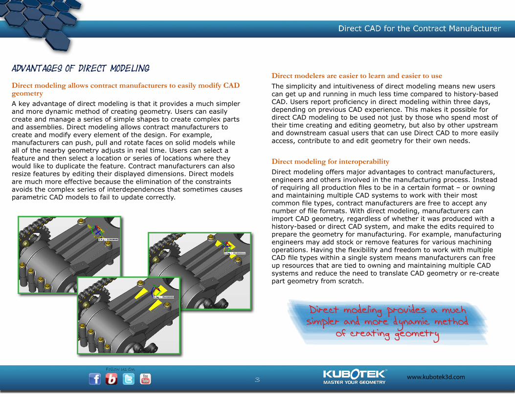
Direct modeling allows contract manufacturers to easily modify CAD geometryA key advantage of direct modeling is that it provides a much simpler and more dynamic method of creating geometry. Users can easily create and manage a series of simple shapes to create complex parts and assemblies. Direct modeling allows contract manufacturers to create and modify every element of the design. For example, manufacturers can push, pull and rotate faces on solid models while all of the nearby geometry adjusts in real time. Users can select a feature and then select a location or series of locations where they would like to duplicate the feature. Contract manufacturers can also resize features by editing their displayed dimensions. Direct models are much more effective because the elimination of the constraints avoids the complex series of interdependences that sometimes causes parametric CAD models to fail to update correctly.
Direct modeling provides a much simpler and more dynamic method
of creating geometry
Direct modelers are easier to learn and easier to useThe simplicity and intuitiveness of direct modeling means new users can get up and running in much less time compared to history-based CAD. Users report proficiency in direct modeling within three days, depending on previous CAD experience. This makes it possible for direct CAD modeling to be used not just by those who spend most of their time creating and editing geometry, but also by other upstream and downstream casual users that can use Direct CAD to more easily access, contribute to and edit geometry for their own needs.
Direct modeling for interoperabilityDirect modeling offers major advantages to contract manufacturers, engineers and others involved in the manufacturing process. Instead of requiring all production files to be in a certain format – or owning and maintaining multiple CAD systems to work with their most common file types, contract manufacturers are free to accept any number of file formats. With direct modeling, manufacturers can import CAD geometry, regardless of whether it was produced with a history-based or direct CAD system, and make the edits required to prepare the geometry for manufacturing. For example, manufacturing engineers may add stock or remove features for various machining operations. Having the flexibility and freedom to work with multiple CAD file types within a single system means manufacturers can free up resources that are tied to owning and maintaining multiple CAD systems and reduce the need to translate CAD geometry or re-create part geometry from scratch.
Follow Us On
www.kubotek3d.com4
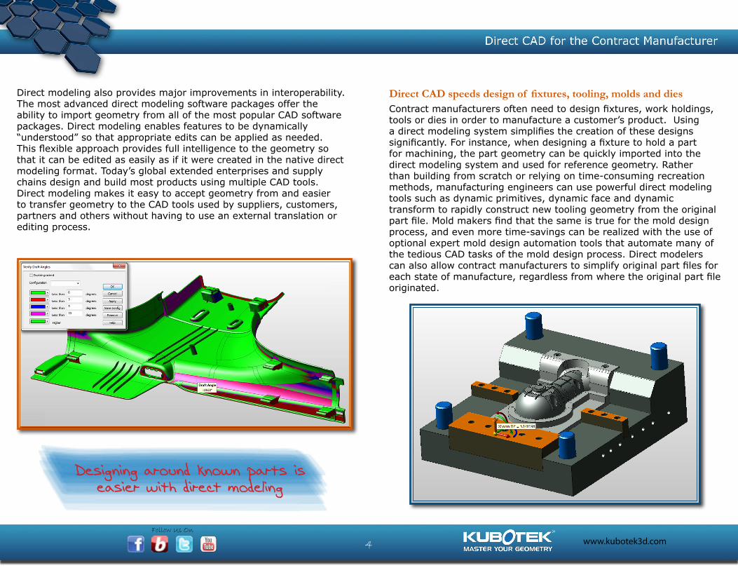
Direct CAD speeds design of fixtures, tooling, molds and dies
Contract manufacturers often need to design fixtures, work holdings, tools or dies in order to manufacture a customer’s product. Using a direct modeling system simplifies the creation of these designs significantly. For instance, when designing a fixture to hold a part for machining, the part geometry can be quickly imported into the direct modeling system and used for reference geometry. Rather than building from scratch or relying on time-consuming recreation methods, manufacturing engineers can use powerful direct modeling tools such as dynamic primitives, dynamic face and dynamic transform to rapidly construct new tooling geometry from the original part file. Mold makers find that the same is true for the mold design process, and even more time-savings can be realized with the use of optional expert mold design automation tools that automate many of the tedious CAD tasks of the mold design process. Direct modelers can also allow contract manufacturers to simplify original part files for each state of manufacture, regardless from where the original part file originated.
Designing around known parts is easier with direct modeling
Direct modeling also provides major improvements in interoperability. The most advanced direct modeling software packages offer the ability to import geometry from all of the most popular CAD software packages. Direct modeling enables features to be dynamically “understood” so that appropriate edits can be applied as needed. This flexible approach provides full intelligence to the geometry so that it can be edited as easily as if it were created in the native direct modeling format. Today’s global extended enterprises and supply chains design and build most products using multiple CAD tools. Direct modeling makes it easy to accept geometry from and easier to transfer geometry to the CAD tools used by suppliers, customers, partners and others without having to use an external translation or editing process.

Follow Us On
www.kubotek3d.com5
Integrating Direct Modeling with CAD comparison
Precise changes to CAD data can be easily viewed and communicatedContract manufacturers frequently need to compare one version of a design to another in order to determine the precise differences between them. This need can occur when engineers or designers propose modifications to the design or are issuing new design revisions. Sometimes changes are initially documented through a redlining process where changes are physically drawn on a design. The redlined CAD file then goes back to the design master and the changes are made. After the changes are complete, the master design file needs to be carefully compared to the redlined file to ensure that the changes are accurately represented. There also needs to be a check that nothing else in the file has accidentally been changed. This same process can repeat in various other downstream operations such as manufacturing, analysis and quality control, all requiring design geometry to be checked against the master design over and over to ensure there is a perfect match.
Design changes can also be unexpectedly introduced by a customer at any point in the production process. Revisions and changes might arrive in the form of a new CAD file where the alterations may or may not be documented. It is up to the contract manufacturer to ensure these changes make it into the manufacturing process and resulting end-product. The only way to ensure the correct file is being used in downstream manufacturing is to do a side by side comparison of the master file and the production file.
Geometric CAD comparison can identify inadvertent changes to CAD data The need to compare CAD files also occur in a third instance when companies switch to a different CAD system. CAD files need to be checked and validated before and after the CAD data translation process to ensure that the files remain geometrically identical.
Direct modeling software integrates CAD comparison capabilities to
accurately document design changes

Follow Us On
www.kubotek3d.com6
Built-in analysis helps deliver better designIntegration of Analysis and CAD can save time and moneyThe traditional approach to engineering designs is to fully define the detailed design then build a physical prototype and test it to evaluate its performance. This approach consumes a lot of time and money. It also limits the number of prototypes that can be built and tested which, in turn, reduces the number of design alternatives that can be considered. Some contract manufacturers use either internal analytical experts or outside consultants (or both) to perform simulations on proposed designs which add to engineering costs. Working with either type of analyst generates delays due to translating the design geometry into the analytical environment and/or communicating the design intent to the analyst. Discussions between the engineer and the analyst over the meaning of the results and constraints on potential improvements to the design also contribute to delays.
The traditional approach to CAD comparison either involves simple overlays, or by placing point clouds on the surface of each of the models and then measuring differences between the positions of corresponding points on the two models. The problem with these approaches is that small features can be easily missed and comparing a sampling of points does not necessarily identify all of the differences between the two files. A more accurate approach uses geometric pattern matching principles to mathematically compare the entire geometry and identify all differences between the files. This approach works with both native CAD files and industry standard neutral file formats.
Comparing both the 3D geometry and the model-based design information, such as tolerances and markings, ensures that all revisions are identified and that the entire impact of every change is fully understood. The latest generation of direct modeling software integrates geometric pattern matching based CAD comparison capabilities so that users can not only view and edit but can also compare CAD files. Integrating this capability with the CAD system makes it possible for contract manufacturers to accurately document design changes throughout the design-to-manufacture process.

Follow Us On
www.kubotek3d.com7
Contract manufacturers using analysis can improve the design prior to prototypingBy providing analysis capabilities within the familiar and user-friendly direct modeling environment, contract manufacturers can evaluate proposed design alternatives in a matter of minutes. Manufacturing engineers can simulate and analyze ways to reduce the cost or amount of material used in the product, providing a value added service to the customer. The integration of CAD and analysis eliminates the need for data translation, for communications between the manufacturing engineer and the analyst, as well as the cost of external analysis capabilities. Manufacturing engineers can evaluate a much greater number of alternatives than was possible in the past which in most cases makes it possible to improve the performance of the design before the physical prototyping stage. The dramatic reduction in time to obtain analysis results also leads to shorter time to market.
Evaluate proposed design alternatives and suggest value-add improvements in a
matter of minutes with integrated analysis
The latest generation of direct modeling software helps overcome this challenge by providing built-in capabilities to analyze the performance of the design within the direct modeling environment. The analysis window provides a natural step-by-step flow for setting up a problem for analysis such as applying loads, constraints and meshes to the solid. Solid models assigned to simulation remain editable with direct modeling functions. When changes are made to models, the loads, constraints and meshes are automatically updated based on the changes. A Strain-Enriched Finite Element Analysis (Sefea) method utilizes a lower number of nodes to support faster solving and uses less system resources while providing results virtually equivalent to legacy methods. This approach makes it possible to solve more complex problems and spend less time simplifying models.
Follow Us On
www.kubotek3d.com8
Integrated CNC programming saves time and avoids errors
Potential for errors are reduced with integrated NCDesign engineers and manufacturing engineers typically work within their own specialized environments. Design engineers use history-based CAD systems that require a considerable learning curve. When the design is finalized, it is normally handed off to a manufacturing engineer or NC programmer who translates the design into another package designed for the task of generating NC tool paths. Working in different environments requires extra time for data translation. With each discipline working with a different model, the potential exists for differences between the models which could result in inadvertent production errors or scrap parts.
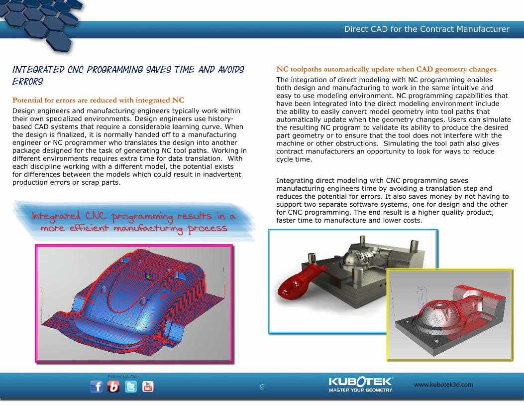
NC toolpaths automatically update when CAD geometry changesThe integration of direct modeling with NC programming enables both design and manufacturing to work in the same intuitive and easy to use modeling environment. NC programming capabilities that have been integrated into the direct modeling environment include the ability to easily convert model geometry into tool paths that automatically update when the geometry changes. Users can simulate the resulting NC program to validate its ability to produce the desired part geometry or to ensure that the tool does not interfere with the machine or other obstructions. Simulating the tool path also gives contract manufacturers an opportunity to look for ways to reduce cycle time.
Integrating direct modeling with CNC programming saves manufacturing engineers time by avoiding a translation step and reduces the potential for errors. It also saves money by not having to support two separate software systems, one for design and the other for CNC programming. The end result is a higher quality product, faster time to manufacture and lower costs.Integrated CNC programming results in a
more efficient manufacturing process

Follow Us On
www.kubotek3d.com9
Advantages of direct modelers with integrated comparison, analysis and manufacturing capabilities
Integrated software options save time and moneyDirect modeling offers major advantages over history-based modeling including the ability to efficiently edit designs regardless of the design origin or by eliminating unnecessary constraints that limit future changes. In selecting direct modeling software, it’s important to consider how it will interface with the complete product development process. Traditional modelers require that users purchase stand-alone CAD comparison, finite element analysis and CNC programming software in order to obtain these essential capabilities. Cost for these tools might range from $1,000 to $10,000 each. User training, administration and support for each individual software package generate additional expenses for each of these tools. Models must be exported and imported from one system to another which takes time and creates the potential for errors.
© 2014 Kubotek Corporation. All rights reserved. Kubotek and KeyCreator are registered trademarks of Kubotek Corporation in the USA. SolidWorks is a trademark of Dassault Systèmes. Pro/ENGINEER is a trademark of PTC, Inc. Inventor is a trademark of Autodesk, Inc.
On the other hand, investing in a direct modeling system with integrated comparison, analysis and CNC programming capabilities makes it possible for contract manufacturers to perform all these critical functions in a single environment, avoiding heavy costs, extended lead times and potential for errors involved in translating data back and forth between environments. Integrating these capabilities with direct modeling also generates considerable cost savings by reducing licensing, training, administration and support expenses. These time and cost savings can have a major impact on the product development process by enabling design engineers to evaluate more design alternatives, ensuring that designs are not corrupted during the engineering change process, and enabling manufacturing engineers and other disciplines to more easily contribute to the design and manufacturing process. The end result will be higher performing products delivered in less time at a lower cost.
Want to learn more about Direct Modeling?Request a KeyCreator Direct CAD demo
or free trial today.kubotek3d.com/keycreator

Follow Us On
www.kubotek3d.com10
Want to learn more about Direct Modeling?Request a KeyCreator Direct CAD demo or free trial today.
kubotek3d.com/keycreator800-372-3872