Diploma i boee u 1 electrostatic and capacitance
76
ELECTROSTATIC AND CAPACITANCE & CURRENT ELECTRICITY Course: Diploma Subject: Basics of Electrical Engineering Unit: I
-
Upload
rai-university -
Category
Education
-
view
212 -
download
0
Transcript of Diploma i boee u 1 electrostatic and capacitance
ELECTROSTATIC AND CAPACITANCE
& CURRENT ELECTRICITY
Course: Diploma
Subject: Basics of Electrical Engineering
Unit: I

What is Static Electricity?
• Static electricity is an imbalance of electric
charges within or on the surface of a material. The
charge remains until it is able to move away by
means of an electric current or electrical discharge.
Static electricity is named in contrast with current
electricity, which flows through wires or other
conductors and transmits energy.
• A static electric charge is created whenever two
surfaces contact and separate, and at least one of the
surfaces has a high resistance to electrical current
(and is therefore an electrical insulator).

What is electric charge?
• Electric charge is the physical property of matter that causes it to experience a force when placed in an electromagnetic field. There are two types of electric charges positive(Protons) and negative(Electrons). Positively charged substances are repelled from other positively charged substances, but attracted to negatively charged substances; negatively charged substances are repelled from negative and attracted to positive. An object will be negatively charged if it has an excess of electrons, and will otherwise be positively charged or uncharged. The SI derived unit of electric charge is the coulomb (C), although in electrical engineering it is also common to use the ampere-hour (Ah), and in chemistry it is common to use the elementary charge (e) as a unit.

What is permittivity?• Permittivity is a measure of how an electric
field affects, and is affected by, a dielectric medium. The permittivity of a medium describes how much electric field (more correctly, flux) is 'generated' per unit charge in that medium.Permittivity is denoted by ‘ε’.
• Permittivity may be of 2 types:-1) permittivity in Vacuum and 2)Absolute permittivity
1) Permittivity in Vaccum is the measure of the resistance that is encountered when forming an electric field in a free space or vacuum .It is denoted ε0
2) Absolute permittivity is the measure of the resistance that is encountered when forming an electric field in a medium . It is denoted by ε

What is Relative permittivity?• The relative permittivity of a material is its
dielectric permittivity expressed as a ratio of absolute to the permittivity of vacuum. It is denoted by ‘Εr. ‘Or ‘K’. The equation for Relative permittivity is as below:
Εr = ε/ε0 = K• Likewise, relative permittivity is the ratio of
the capacitance of a capacitor using that material as a dielectric, compared to a similar capacitor that has vacuum as its dielectric. Relative permittivity is also commonly known as dielectric constant, a term deprecated in physics and engineering.

Coulomb’s law for electric charge• The magnitude of the electrostatic force of
interaction between two point charges is directly
proportional to the scalar multiplication of the
magnitudes of charges and inversely proportional to the
square of the distance between them.The force is along
the straight line joining them. If the two charges have the
same sign, the electrostatic force between them is
repulsive; if they have different sign, the force between
them is attractive.Mathematically it can be represented
by followindg formula,

What is Electric field?• Electric field is defined as the electric force per
unit charge. The direction of the field is taken to be the direction of the force it would exert on a positive test charge. The electric field is radially outward from a positive charge and radially in toward a negative point charge…The equation for electrisc field is given by following formula:-
E = F/q and the unit of electric field is N/C.
Electric field from a point charge : E = k Q / r2

Continue…
Fig 1

Cont…In above figure electric field lines are shown.
What is electric field lines?
A more useful means of visually representing the vector nature of an electric field is through the use of electric field lines of force. Rather than draw countless vector arrows in the space surrounding a source charge, it is perhaps more useful to draw a pattern of several lines that extend between infinity and the source charge. These pattern of lines, sometimes referred to as electric field lines, point in the direction that a positive test charge would accelerate if placed upon the line.
Cont..
• As such, the lines are directed away from positively
charged source charges and toward negatively
charged source charges. To communicate
information about the direction of the field, each line
must include an arrowhead that points in the
appropriate direction.

Cont…
• An electric field line pattern could include an infinite number of lines. Because drawing such large quantities of lines tends to decrease the readability of the patterns, the number of lines is usually limited. The presence of a few lines around a charge is typically sufficient to convey the nature of the electric field in the space surrounding the lines
What is electric field intensity?
• Electric field strength is a vector quantity; it has both magnitude and direction. The magnitude of the electric field strength is defined in terms of how it is measured. Let's suppose that an electric charge can be denoted by the symbol Q.
• This electric charge creates an electric field; since Q is the source of the electric field, we will refer to it as the source charge. The strength of the source charge's electric field could be measured by any other charge placed somewhere in its surroundings.

Cont..
• The charge that is used to measure the electric field strength is referred to as a test charge since it is used to test the field strength. The test charge has a quantity of charge denoted by the symbol q. When placed within the electric field, the test charge will experience an electric force -either attractive or repulsive. As is usually the case, this force will be denoted by the symbol F. The magnitude of the electric field is simply defined as the force per charge on the test charge.
Cont..
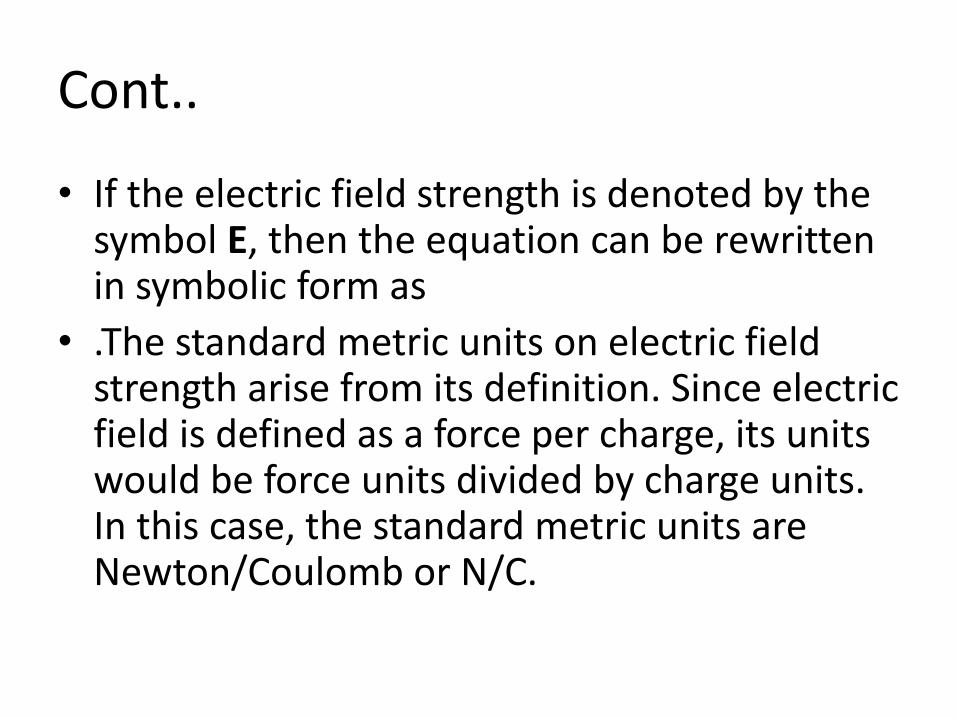
• If the electric field strength is denoted by the symbol E, then the equation can be rewritten in symbolic form as
• .The standard metric units on electric field strength arise from its definition. Since electric field is defined as a force per charge, its units would be force units divided by charge units. In this case, the standard metric units are Newton/Coulomb or N/C.

ELECTRIC FLUX
• Think of air blowing in through a window. How much air comes through the window depends upon the speed of the air, the direction of the air, and the area of the window. We might call this air that comes through the window the "air flux".
• We will define the electric flux for an electric field that is perpendicular to an area as
• ɸ = E.A

Cont..
• Think about the "air flux" of air passing through a window at an angle . The "effective area" is A cos or the component of the velocity perpendicular to the window is v cos . With this in mind, we will make a general definition of the electric flux as
ɸ = E A cosθ
You can also think of the electric flux as the number of electric field lines that cross the surface. Remembering the "dot product" or the "scalar product", we can also write this as
ɸ = E . A
• where E is the electric field and A is a vector equal to area

Cont..• where n is a unit vector pointing perpendicular to
the area. In that case, we could also write the electric flux across an area as
ɸ = E . n A
• Both forms say the same thing. For this to make any sense, we must be talking about an area where the direction of A or n is constant.
• For a curved surface, that will not be the case. For that case, we can apply this definition of the electric flux over a small area & δA or A or δAn.

Cont..
• Electrical flux has SI units of volt metres (V m), or, equivalently, newton metres squared per coulomb (N m2 C−1). Thus, the SI base units of electric flux arekg·m3·s−3·A−1.
• Its dimensional formula is [L3MT–3I–1].

CAPACITOR• A capacitor (originally known as a condenser) is
a passive two-terminal electrical component used to storeenergy electrostatically in an electric field. The forms of practical capacitors vary widely, but all contain at least two electrical conductors (plates) separated by a dielectric (i.e., insulator). The conductors can be thin films of metal, aluminum foil or disks, etc. The 'nonconducting' dielectric acts to increase the capacitor's charge capacity. A dielectric can be glass, ceramic, plastic film, air, paper, mica, etc. Capacitors are widely used as parts of electrical circuits in many common electrical devices. Unlike a resistor, a capacitor does not dissipate energy. Instead, a capacitor stores energy in the form of an electrostatic field between its plates.
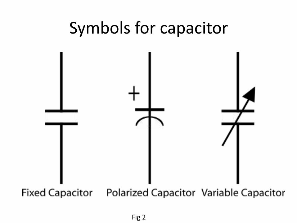
Symbols for capacitor
Fig 2
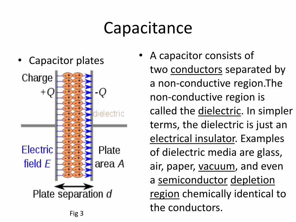
Capacitance
• Capacitor plates • A capacitor consists of two conductors separated by a non-conductive region.Thenon-conductive region is called the dielectric. In simpler terms, the dielectric is just an electrical insulator. Examples of dielectric media are glass, air, paper, vacuum, and even a semiconductor depletion region chemically identical to the conductors.
Fig 3
Cont• The conductors thus hold equal and opposite charges on
their facing surfaces, and the dielectric develops an electric field. In SI units, a capacitance of one farad means that one coulomb of charge on each conductor causes a voltage of one volt across the device.
• An ideal capacitor is wholly characterized by a constant capacitance C, defined as the ratio of charge ±Q on each conductor to the voltage V between them:

Cont..
• Because the conductors (or plates) are close together, the opposite charges on the conductors attract one another due to their electric fields, allowing the capacitor to store more charge for a given voltage than if the conductors were separated, giving the capacitor a large capacitance.
• Sometimes charge build-up affects the capacitor mechanically, causing its capacitance to vary. In this case, capacitance is defined in terms of incremental changes:
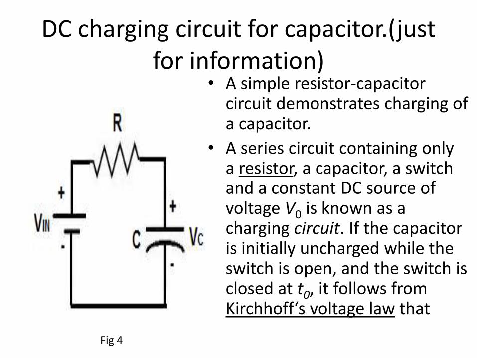
DC charging circuit for capacitor.(just for information)
• A simple resistor-capacitor circuit demonstrates charging of a capacitor.
• A series circuit containing only a resistor, a capacitor, a switch and a constant DC source of voltage V0 is known as a charging circuit. If the capacitor is initially uncharged while the switch is open, and the switch is closed at t0, it follows from Kirchhoff‘s voltage law that
Fig 4

Cont..we can get following equation by kirchoff’s law
• Taking the derivative and multiplying by C, gives a first-order differential equation
• At t = 0, the voltage across the capacitor is zero and the voltage across the resistor is V0. The initial current is then I(0) =V0/R. With this assumption, solving the differential equation yields

Cont…• where τ0 = RC is the time constant of the system.
As the capacitor reaches equilibrium with the source voltage, the voltages across the resistor and the current through the entire circuit decay exponentially. The case of discharging a charged capacitor likewise demonstrates exponential decay, but with the initial capacitor voltage replacing V0 and the final voltage being zero.
Cont…• taking the derivative and multiplying by C, gives
a first-order differential equation:At t = 0, the voltage across the capacitor is zero
and the voltage across the resistor is V0. The initial current is then I(0) =V0/R. With this assumption, solving the differential equation yields
• where τ0 = RC is the time constantof the system. As the capacitor reaches equilibrium with the source voltage, the voltages across the resistor and the current through the entire circuit decay exponentially. The case of discharging a charged capacitor likewise demonstrates exponential decay, but with the initial capacitor voltage replacing V0 and the final voltage being zero.

Series and parellel connection of capacitor
• Capacitors are one of the standard components in electronic circuits. Moreover, complicated combinations of capacitors often occur in practical circuits. It is, therefore, useful to have a set of rules for finding the equivalent capacitance of some general arrangement of capacitors. It turns out that we can always find the equivalent capacitance by repeated application of two simple rules. These rules related to capacitors connected in series and in parallel.

Circuits
Fig 5
Parellel connection
• Consider two capacitors connected in parallel: i.e., with the positively charged plates connected to a common ``input'' wire, and the negatively charged plates attached to a common ``output'' wire--see Fig. 15. What is the equivalent capacitance between the input and output wires? In this case, the potential difference across the two capacitors is the same, and is equal to the potential difference between the input and output wires. The total charge

Cont..
• however, stored in the two capacitors is divided between the capacitors, since it must distribute itself such that the voltage across the two is the same. Since the capacitors may have different capacitances, and the charges and may also be different. The equivalent capacitance of the pair of capacitors is simply the ratio . Where is total charge. It follows that

Cont..
• Here, we have made use of the fact that the voltage is common to all three capacitors. Thus, the rule is:
• The equivalent capacitance of two capacitors connected in parallel is the sum of the individual capacitances.
• For capacitors connected in parallel, above Eq. generalizes to
Series connection
• Consider two capacitors connected in series: i.e., in a line such that the positive plate of one is attached to the negative plate of the other--see Fig. 16. In fact, let us suppose that the positive plate of capacitor 1 is connected to the ``input'' wire, the negative plate of capacitor 1 is connected to the positive plate of capacitor 2, and the negative plate of capacitor 2 is connected to the ``output'' wire. What is the equivalent capacitance between the input and output wires? In this case, it is important to realize that the charge Q

Cont..• stored in the two capacitors is the same. This is most
easily seen by considering the ``internal'' plates: i.e., the negative plate of capacitor 1, and the positive plate of capacitor 2. These plates are physically disconnected from the rest of the circuit, so the total charge on them must remain constant. Assuming, as seems reasonable, that these plates carry zero charge when zero potential difference is applied across the two capacitors, it follows that in the presence of a non-zero potential difference the charge +Q on the positive plate of capacitor 2 must be balanced by an equal and opposite charge -Q on the negative plate of capacitor 1. Since the negative plate of capacitor 1 carries a charge -Q the positive plate must carry a charge +Q .

• The potential drops, V1 and V2 , across the two capacitors are, in general, different. However, the sum of these drops equals the total potential drop V applied across the input and output wires: i.e.,V= V1 + V2. The equivalent capacitance of the pair of capacitors is again . Thus,
Cont..
What is electricity?
• Electricity is the set of physical phenomena associated with the presence and flow of electric charge. Electricity gives a wide variety of well-known effects, such as lightning, static electricity, electromagnetic induction and electrical current. In addition, electricity permits the creation and reception of electromagnetic radiation such as radio waves.
• In electricity, charges produce electromagnetic fields which act on other charges.

What is electric current?
• An electric current is a flow of electric charge. In electric circuits this charge is often carried by moving electrons in a wire. It can also be carried by ions in an electrolyte, or by both ions and electrons such as in a plasma.
• The SI unit for measuring an electric current is the ampere, which is the flow of electric charges through a surface at the rate of one coulomb per second. Electric current can be measured using an ammeter
Ohm’s law
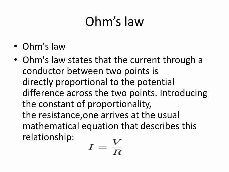
• Ohm's law
• Ohm's law states that the current through a conductor between two points is directly proportional to the potential difference across the two points. Introducing the constant of proportionality, the resistance,one arrives at the usual mathematical equation that describes this relationship:

Cont..
• where I is the current through the conductor in units of amperes, V is the potential difference measured across the conductor in units of volts, and R is the resistance of the conductor in units of ohms. More specifically, Ohm's law states that the R in this relation is constant, independent of the current

What is AC and DC?• Direct current• Direct current (DC) is the unidirectional flow
of electric charge. Direct current is produced by sources such as batteries, thermocouples, solar cells, and commutator-type electric machines of the dynamo type. Direct current may flow in a conductor such as a wire, but can also flow through semiconductors, insulators, or even through a vacuum as in electron or ion beams. The electric charge flows in a constant direction, distinguishing it from alternating current (AC). A term formerly used for direct current was galvanic current.
Alternating current• In alternating current (AC, also ac), the movement
of electric charge periodically reverses direction. In direct current (DC, also dc), the flow of electric charge is only in one direction.
• AC is the form in which electric power is delivered to businesses and residences. The usual waveform of an AC power circuit is a sine wave. In certain applications, different waveforms are used, such as triangular or square waves. Audio and radio signals carried on electrical wires are also examples of alternating current. In these applications, an important goal is often the recovery of information encoded (or modulated) onto the AC signal.

What is resistor?• Resistor• A resistor is a passive two-terminal electrical
component that implements electrical resistance as a circuit element. Resistors act to reduce current flow, and, at the same time, act to lower voltage levels within circuits. Resistors may have fixed resistances or variable resistances, such as those found in thermistors, varistors, trimmers, photoresistors,humistors, piezoresistors and potentiometers.
• The current through a resistor is in direct proportion to the voltage across the resistor's terminals. This relationship is represented by Ohm's law:

Resistivity• The resistance of a given object depends primarily
on two factors: What material it is made of, and its shape. For a given material, the resistance is inversely proportional to the cross-sectional area; for example, a thick copper wire has lower resistance than an otherwise-identical thin copper wire. Also, for a given material, the resistance is proportional to the length; for example, a long copper wire has higher resistance than an otherwise-identical short copper wire. The resistance R and conductance G of a conductor of uniform cross section, therefore, can be computed as

Cont..• where L is the length of the conductor, measured
in meters, A is the cross-section area of the conductor measured in square meters [m²], σ (sigma) is the electrical conductivity measured in Siemens per meter (S·m−1), and ρ (rho) is the electrical resistivity (also called specific electrical resistance) of the material, measured in ohm-metres (Ω·m). The resistivity and conductivity are proportionality constants, and therefore depend only on the material the wire is made of, not the geometry of the wire. Resistivity and conductivity are reciprocals:
• Resistivity is a measure of the material's ability to oppose electric current.

Cont..
• The total resistance of resistors in series is equal to the sum of their individual resistances:

cont..
• The current in each individual resistor is found by Ohm's law. Factoring out the voltage gives
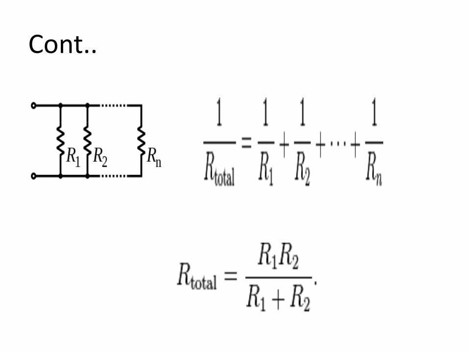
• To find the total resistance of all components, add the reciprocals of the resistances of each component and take the reciprocal of the sum. Total resistance will always be less than the value of the smallest resistance
Cont..
Cont..
• In electronics, a shunt is a device which allows electric current to pass around another point in the circuit by creating a low resistance path.
• Use in current measuring. 50 A shunt resistor

Cont..
• An ammeter shunt allows the measurement of current values too large to be directly measured by a particular ammeter. In this case the shunt, a manganin resistor of accurately known resistance, is placed in series with the load so that all of the current to be measured will flow through it.

Cont..
• In order not to disrupt the circuit, the resistance of the shunt is normally very small. The voltage drop across the shunt is proportional to the current flowing through it and since its resistance is known, a voltmeter connected across the shunt can be scaled to directly display the current value.

Wheatstone bridge.
A Wheatstone bridge is an electrical circuit used to measure an unknown electrical resistance by balancing two legs of a bridge circuit, one leg of which includes the unknown component. Its operation is similar to the original potentiometer.
Fig 6

Cont..
• In the figure, is the unknown resistance to be measured; , and are resistors of known resistance and the resistance of is adjustable. If the ratio of the two resistances in the known leg is equal to the ratio of the two in the unknown leg , then the voltage between the two midpoints (B and D) will be zero and no current will flow through the galvanometer . If the bridge is unbalanced, the direction of the current indicates whether is too high or too low. is varied until there is no current through the galvanometer, which then reads zero.
Cont..
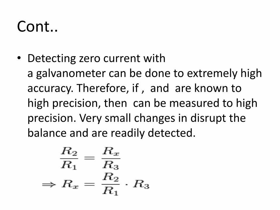
• Detecting zero current with a galvanometer can be done to extremely high accuracy. Therefore, if , and are known to high precision, then can be measured to high precision. Very small changes in disrupt the balance and are readily detected.

Derivation
• First, Kirchhoff's first rule is used to find the currents in junctions B and D:
• Then, Kirchhoff's second rule is used for finding the voltage in the loops ABD and BCD:

• When the bridge is balanced, then IG = 0, so the second set of equations can be rewritten as:
• Then, the equations are divided and rearranged, giving:

Cont…• From the first rule, I3 = Ix and I1 = I2. The desired value
of Rx is now known to be given as:
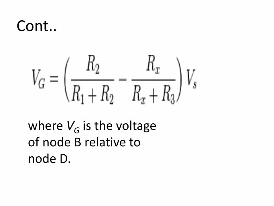
• If all four resistor values and the supply voltage (VS) are known, and the resistance of the galvanometer is high enough that IG is negligible, the voltage across the bridge (VG) can be found by working out the voltage from each potential divider and subtracting one from the other. The equation for this is:
Cont..
where VG is the voltage of node B relative to node D.
Cont..• The value of a resistor changes with changing
temperature, but this is not as we might expect, mainly due to a change in the dimensions of the component as it expands or contracts. It is due mainly to a change in the resistivity of the material caused by the changing activity of the atoms that make up the resistor.
• Materials which are classed as CONDUCTORS tend to INCREASE their resistivity with an increase in temperature. INSULATORS however are liable to DECREASE their resistivity with an increase in temperature. Materials used for practical insulators (glass, plastic etc) only exhibit a marked drop in their resistivity at very high temperatures. They remain good insulators over all temperatures they are likely to encounter in use.
Cont..
• The reasons for these changes in resistivity can be explained by considering the flow of current through the material. The flow of current is actually the movement of electrons from one atom to another under the influence of an electric field. Electrons are very small negatively charged particles and will be repelled by a negative electric charge and attracted by a positive electric charge. Therefore if an electric potential is applied across a conductor (positive at one end, negative at the other) electrons will "migrate" from atom to atom towards the positive terminal.

Cont..
• Only some electrons are free to migrate however. Others within each atom are held so tightly to their particular atom that even an electric field will not dislodge them. The current flowing in the material is therefore due to the movement of "free electrons" and the number of free electrons within any material compared with those tightly bound to their atoms is what governs whether a material is a good conductor (many free electrons) or a good insulator (hardly any free electrons).

Cont..• The effect of heat on the atomic structure of a material
is to make the atoms vibrate, and the higher the temperature the more violently the atoms vibrate.
• In a conductor, which already has a large number of free electrons flowing through it, the vibration of the atoms causes many collisions between the free electrons and the captive electrons. Each collision uses up some energy from the free electron and is the basic cause of resistance. The more the atoms jostle around in the material the more collisions are caused and hence the greater the resistance to current flow.
• In an insulator however, there is a slightly different situation. There are so few free electrons that hardly any current can flow. Almost all the electrons are tightly bound within their particular atom.

Cont..• In A material where the resistance increases with temperature
it is said that the material has A positive temperature coefficient.
• When resistance falls with an increase in temperature the material is said to have a negative temperature coefficient.
• In general, conductors have a positive temperature coefficient
• Whilst (at high temperatures) insulators have A negative temperature coefficient.
• Different materials within either group have different temperature coefficients. Materials chosen for the construction of resistors therefore are most likely to be carefully selected conductors that have A very low positive temperature coefficient. In use, resistors made from such materials will have only very slight increases in resistivity, and therefore resistance, as temperature rises.

HEATING EFFECT OF ELECTRIC CURRENT: JOULE'S LAW
• The electric current in a conductor is due to the motion of electrons. During their motion, electrons collide with the oscillating positive ions in the conductor and impart part of their energy to them. Ions oscillate faster and their increased energy is manifested as heat. The heat energy released in a conductor on passing an electric current is called the “Joule heat” and effect is called the ‘Joule effect”. The potential difference of V volt applied between two ends of a conductor means that V joule of electrical energy is utilized and converted into heat when one coulomb charge passes through the conductor. If Q coulomb charge passes through the conductor in t seconds resulting in current I, the heat energy produced is

Cont..• W = V Q
= V I t= I 2 R t ( Q V = I R according to Ohm’s law )= ( V 2/ R )
The electric power, i. e., the electrical energy supplied per unit time or converted into heat energy per unit time in a resistance R, isP = V I
= I 2 R= ( V 2/ R
Thus, mechanical unit of energy, joule = watt. second which is an electrical unit of energy. This being too small, kilowatt-hour ( kwh ) = 3.6 × 10⁶ joule is used as a practical unit of electrical energy. R is the Ohmic resistance of the conductor value of which does not depend upon V or I. Considering R as a constant, P is proportional to I 2 or P is proportional to V 2.

Cont..• Joule’s Law: - “The heat produced per unit time,
on passing electric current through a conductor at a given temperature, is directly proportional to the square of the electric current”.To express heat produced in calories, the following relation given by Joule is used.W = JH where W is mechanical energy in joule,H is heat energy in calorieand J = 4.2 joule / calorie is Joule’s constant or mechanical equivalent of heat.

Electric power and energy• Electric power is the rate at which electric energy is
transferred by an electric circuit. The SI unit of power is the watt, one joule per second.
• Electric power is usually produced by electric generators, but can also be supplied by sources such as electric batteries. Electric power is generally supplied to businesses and homes by the electric power industry. Electric power is usually sold by the kilowatt hour (3.6 MJ) which is the product of power in kilowatts multiplied by running time in hours.
• Electric power, like mechanical power, is the rate of doing work, measured in watts, and represented by the letter P.

cont..
Q is electric charge in coulombs t is time in seconds I is electric current in amperes V is electric potential or voltage in volts.
Electrical energy• When loosely used to describe energy absorbed or
delivered by an electrical circuit (for example, one provided by an electric power utility) "electrical energy" refers to energy which has been converted from electrical potential energy. This energy is supplied by the combination of electric current and electrical potential that is delivered by the circuit. At the point that this electrical potential energy has been converted to another type of energy, it ceases to be electrical potential energy. Thus, all electrical energy is potential energy before it is delivered to the end-use. Once converted from potential energy, electrical energy can always be described as another type of energy (heat, light, motion, etc.).

What is thermocouple?• A thermocouple is a temperature-measuring device
consisting of two dissimilar conductors that contact each other at one or more spots. It produces a voltage when the temperature of one of the spots differs from the reference temperature at other parts of the circuit. Thermocouples are a widely used type of temperature sensor for measurement and control,and can also convert a temperature gradient into electricity. Commercial thermocouples are inexpensive,interchangeable, are supplied with standard connectors, and can measure a wide range of temperatures. In contrast to most other methods of temperature measurement, thermocouples are self powered and require no external form of excitation. The main limitation with thermocouples is accuracy; system errors of less than one degree Celsius (°C) can be difficult to achieve.

Cont..
• Any junction of dissimilar metals will produce an electric potential related to temperature. Thermocouples for practical measurement of temperature are junctions of specific alloys which have a predictable and repeatable relationship between temperature and voltage. Different alloys are used for different temperature ranges. Properties such as resistance to corrosion may also be important when choosing a type of thermocouple. Where the measurement point is far from the measuring instrument, the intermediate connection can be made by extension wires which are less costly than the materials used to make the sensor. Thermocouples are usually standardized against a reference temperature of 0 degrees Celsius; practical instruments use electronic methods of cold-junction compensation to adjust for varying temperature at the instrument terminals.

See back effect• The conversion of temperature difference to electric current
and vice-versa is termed as thermoelectric effect. In 1981,
Thomas Johann See beck found that a circuit with two
dissimilar metals with different temperature junctions would
deflect a compass magnet. He realised that there was an
induced electric current, which by Ampere's law deflect the
magnet. Also electric potential or voltage due to the
temperature difference can drive the electric current in the
closed circuit.
• To measure this voltage, one must use a second conductor
material which generates a different voltage under the same
temperature gradient.

Cont..• V- Voltage difference between two dissimilar metals
• a- Seebeck coefficient
• Th - Tc - Temperature difference between hot and cold junctions
•
• There are three major effects involved in a thermocouple circuit: the Seebeck, Peltier, and Thomson effects.
• The Seebeck effect describes the voltage or electromotive force (EMF) induced by the temperature difference (gradient) along the wire. The change in material EMF with respect to a change in temperature is called the Seebeck coefficient or thermoelectric sensitivity. This coefficient is usually a nonlinear function of temperature.
•

References-Images• https://www.google.co.in/url?sa=i&rct=j&q=&esrc=s&source=images&cd=&cad=rja&uact=8&ved=
0CAcQjRw&url=http%3A%2F%2Fphysics.bu.edu%2F~duffy%2FPY106%2FElectricfield.html&ei=-JSjVMS9PIzhuQSvkIHACQ&bvm=bv.82001339,d.c2E&psig=AFQjCNHRlFXJqrWpUJ1EGD9TstY_M64JMw&ust=1420092690355196
• https://www.google.co.in/url?sa=i&rct=j&q=&esrc=s&source=images&cd=&cad=rja&uact=8&ved=0CAcQjRw&url=http%3A%2F%2Fimgarcade.com%2F1%2Fcapacitor-symbol%2F&ei=kJWjVMXXC4vmuQSl-IKIBQ&bvm=bv.82001339,d.c2E&psig=AFQjCNFmUEosk32DchE1jsUeATwfj95qeA&ust=1420093173981775
• https://www.google.co.in/url?sa=i&rct=j&q=&esrc=s&source=images&cd=&cad=rja&uact=8&ved=0CAcQjRw&url=http%3A%2F%2Fen.wikipedia.org%2Fwiki%2FDielectric&ei=UZajVOurG4KzuATIiYLQAw&bvm=bv.82001339,d.c2E&psig=AFQjCNFOooTuOPV7WixunoloNKLyWUr3aQ&ust=1420093378519694
• https://www.google.co.in/url?sa=i&rct=j&q=&esrc=s&source=images&cd=&cad=rja&uact=8&ved=0CAcQjRw&url=%2Furl%3Fsa%3Di%26rct%3Dj%26q%3D%26esrc%3Ds%26source%3Dimages%26cd%3D%26cad%3Drja%26uact%3D8%26ved%3D0CAcQjRw%26url%3Dhttp%253A%252F%252Fwww.learningaboutelectronics.com%252FArticles%252FCapacitor-charge-calculator.php%26ei%3D6ZijVJWrNtGiugSIh4HwCQ%26bvm%3Dbv.82001339%2Cd.c2E%26psig%3DAFQjCNEtOhL5sGu3jt8ymQ0TtsGHSLj7Nw%26ust%3D1420093963260726&ei=6ZijVJWrNtGiugSIh4HwCQ&bvm=bv.82001339,d.c2E&psig=AFQjCNEtOhL5sGu3jt8ymQ0TtsGHSLj7Nw&ust=1420093963260726

• https://www.google.co.in/url?sa=i&rct=j&q=&esrc=s&source=images&cd=&cad=rja&uact=8&ved=0CAcQjRw&url=http%3A%2F%2Fmysite.avemaria.edu%2Fjcdaly%2Fphys223%2Flab%2FLab3RCcircuits%2FRCcircuitsPart2.html&ei=4JqjVNP_F4qTuAS7joDQCQ&bvm=bv.82001339,d.c2E&psig=AFQjCNH_d4ctxGgOxBBVkbxNwvcFqgp8bg&ust=1420094487687656
• https://www.google.co.in/url?sa=i&rct=j&q=&esrc=s&source=images&cd=&cad=rja&uact=8&ved=0CAcQjRw&url=http%3A%2F%2Fen.wikipedia.org%2Fwiki%2FWheatstone_bridge&ei=4KWjVP-nIcSTuASQ_YKABw&bvm=bv.82001339,d.c2E&psig=AFQjCNGWzdd4-i7-cXKGXerrwUNxt_iW3A&ust=1420097380016548
REFERENCE
• B.L.Theraja, “Electrical Technology Vol.1”, S.ChandPublication.
• D.P.Kothari, “Basic Electrical Engineering”, Tata McGraw-Hill publication.
• U.A.Patel “Circuits and Networks”.