Dimensions - Bigge · PDF fileCarrier specifications RT500C 5 Chassis High strength alloy...
18
-
Upload
phungthien -
Category
Documents
-
view
214 -
download
0
Transcript of Dimensions - Bigge · PDF fileCarrier specifications RT500C 5 Chassis High strength alloy...


RT500C2
Dimensions
Note: ( ) Reference dimensions in mm
18' 8-3/8" (5709)
1' 7" (483)
1' 5-3/16" (436)
1' 5-3/16" (436)
1' 7-3/16" (487)
2' 1" (633)
3' (914)
20' 4-1/2" (6210)
7' 6" (2286) RET
19' (5791) EXT
13' 6" (4115) MID EXT
10' 3-1/8" (3127)
TAILSWING
A B
C ROTATIONL
24° 20°
11' 2-1/4" (3410)
15' 2-1/2" (4636)
9' 2-1/4" (2800)
9' 6-1/2" (2908)
21' 7-1/8" (6582)
10' 1" (3073) WHEELBASE
10' 11-13/16" (3348)
36' 9-5/8" (11 218)
Turning Radius . . . . . . . . . . . .
17' 0” (5182 mm)
Front Axle Load . . . . . . . . . . . 23,959 lbs. (10 868 kg)
Rear Axle Load. . . . . . . . . . . . 29,094 lbs. (13 197 kg)
Gross Vehicle Weight . . . . . . . 53,053 lbs. (24 065 kg)
TIRE SIZE 16.00 x 25 20.5 x 25
A (TRACK) 6’ 5-1/2” (1969) 6’ 9-1/8” (2061)
B (OAW) 8’ (2438) 8’ 9” (2667)
GROUND CLEARANCE 1’ 7-1/8” (486)

28 - 70 ft. (8.5 - 21.3 m)
25 - 43 ft. (7.6 - 13.1 m)
360°
4' - 6" 2' - 7"DIMENSIONS ARE FOR LARGEST GROVE FURNISHED HOOK BLOCK AND HEADACHE BALL, WITH ANTI - TWO BLOCK ACTIVATED.
AXIS OF ROTATION
130
FEET
FEET
120
110
100
90
80
70
60
50
40
30
20
10
0
120 110 100 90 80 70 60 50 40 30 20
0°
10°
20°
30°
40°
50°
60°
70° 70
64
58
52
46
40
34
28
75°MAX
BOOM ANGLE
43
34
25
0°
15°
30°
3
Working range
RT500C

RT500C
Superstructure specifications
4
Boom
28 ft. - 70 ft. (8.5 m - 21.3 m) three-section, full powerboom. Maximum tip height: 76 ft. (23.1 m).
*Optional Jib23 ft. (7.1 m) “A” frame jib offsettable at 0°, 15° or 30°.Stows beneath base boom section.Maximum tip height: 98 ft. (29.9 m).
*Optional Swingaway Extension25 ft. (7.6 m) lattice swingaway boom extension. Stowsalongside base boom section.Maximum tip height: 102 ft. (31.0 m).
*Optional TelescopicSwingaway Extension25 ft. to 34 ft. or 43 ft. (7.6 m to 10.4 m or 13.1 m)telescoping lattice swingaway extension with integraloffset mechanism, offsettable at 0°, 15° or 30°. Stowsalongside base boom section.Maximum tip height: 120 ft. (36.6 m).
Boom NoseFour steel sheaves mounted on heavy duty taperedroller bearings with removable pin-type rope guards.*Optional removable auxiliary boom nose withremovable pin type rope guard.
Boom Elevation Two double acting hydraulic cylinders with integral holding valves provide elevation from 0° to 75°.
Load Moment & Anti-Two Block SystemStandard load moment and anti-two block system with audio-visual warning and control lever lockout. These systems provide electronic display of boom angle,length, radius, tip height, relative load moment,maximum permissible load, load indication and warningof impending two-block condition.
CabFull vision, all steel fabricated with acoustical lining andtinted safety glass throughout. Deluxe seat incorporatesarmrest mounted hydraulic single-axis controllers. Dashpanel incoporates gauges for all engine functions. Otherstandard features include: telescoping tilt steeringwheel, sliding side and rear windows, electricwindshield wash/wipe, circulating air fan, manualskylight wiper, fire extinguisher, seat belt and ashtray.
Swing Ball bearing swing circle with 360° continuous rotation.Grove planetary glide-swing with multi-disc wet brake.Spring applied, hydraulically released parking brake andplunger-type, one position, mechanical house lock and360° positive swing lock operated from cab.Maximum speed: 2.5 RPM.
Counterweight Removable, bolted to turntable mast.Main hoist: 10,170 lbs. (4613 kg).Main and Auxiliary hoist: 9,120 lbs. (4136 kg).
Hydraulic System 3 main gear pumps with a combined capacity of 112.5GPM (426 LPM) driven by carrier engine through P.T.O.*Optional pump disconnect with engine jogging switch.Maximum operating pressure: 2500 PSI (172.4 bar).
Hoist SpecificationsMain or *Auxiliary HoistPower up and down equal speed, grooved drum,planetary reduction with automatic spring appliedmulti-disc brake, hoist drum rotation indicators, cablefollowers.
Maximum Single 429 FPMLine Speed: (131 m/min)
Maximum Single 9,640 lbs.Line Pull (1st Layer): (4372 kg)
Maximum Permissible 9,080 lbs.Line Pull w/5:1 (4119 kg)Strength Factor: 5/8 in. (16 mm)
18 x 19 class
Maximum Rope Stowage: 375 ft. (114 m)5/8 in. (16 m)
*Denotes optional equipment

Carrier specifications
5RT500C
ChassisHigh strength alloy steel, all welded box section designwith integral outrigger housings and front/rear lifting,towing and tie down lugs.
Outrigger SystemFour hydraulic, telescoping, single-stage, double boxbeam outriggers with inverted jacks and integral holding valves. Three position setting. All steel fabricated, quick release type square outrigger floats,16.5 in. (419 mm) diameter.Maximum outrigger pad load: 50,254 lbs. (22 795 kg).
Outrigger ControlsControls and crane level indicator located in cab.
EngineCummins 6BT 5.9 L, six cylinder, turbocharged, watercooled diesel. 130 bhp (97 kW) (Gross) @ 2,500 RPM.Maximum torque: 386 ft. lbs. (523 Nm) @ 1,400 RPM.
Fuel Tank Capacity60 gallons (227 L)
TransmissionRemote mounted powershift with 6 forward and 6reverse speeds. 3 in high range, 3 in low range. Rear axledisconnect for 4 x 2 travel.
Electrical SystemTwo 12 V - maintenance free batteries, 625 CCA @ 0° F.12 V starting and lighting.
Drive4 x 4.
SteeringFully independent power steering:Front: Full hydraulic steering wheel controlled.Rear: Full hydraulic hand lever controlled.Provides infinite variations of 4 main steering modes: front only, rear only, crab and coordinated.
AxlesFront: Drive/steer with differential and planetary
reduction hubs rigid mounted to chassis.Rear: Drive/steer with differential and planetary
reduction hubs pivot mounted at the center of chassis providing up to 12 in. (305 mm)oscillation.
*Optional: No spin differential on rear axle.
Oscillation Lockouts Automatic full hydraulic lockouts on rear axle permitoscillation only with boom centered over the front.*Optional oscillation lockout override control.
BrakesDual braking system, air over hydraulic operating on allwheels. Spring-applied, air released front axle mountedparking brake.
Tires20.5 x 25 - 24PR earthmover type, tubeless.*16.00 x 25 - 28PR earthmover type, tubeless.
LightsFull lighting package including turn indicators, head,tail, brake and hazard warning lights.
Maximum Speed22.8 MPH (36.7 kph).
Gradeability (Theoretical)110.5% (Based on 51,610 lbs. [23 410 kg] GVW) 20.5 x25 tires, pumps disengaged, 70 ft. (21.3 m) boom.
Miscellaneous Standard EquipmentFull width steel fenders, dual rear view mirrors,hookblock tiedown sling, electronic back-up alarm, lightpackage, front stowage well, control valve for auxiliaryhoist, 360° positive swing lock.
*Optional Equipment
*Denotes optional equipment
*Auxiliary hoist*Boom mountedworklights
*360° flashing light*Cab spotlight*Tachometer*Cold start aid(less canister)
*Engine block heater*Electric skylight wiper,with opening skylight
*Hookblocks*Tow winch - front mounted maximum pull:15,000 lbs. (6804 kg);maximum speed: 75 ft/min. (23 m/min).
*Spare wheel assembly*Tire inflation kit*Tool kit*Pintle hook front/rear*High speed glide system*Propane or diesel heater/defroster
*Air conditioning*Dual axis joystickcontrollers
*Hydraulic oil cab heater*Headache ball*Emergency steer pump*LMI light bar

6 RT500C
THIS CHART IS ONLY A GUIDE AND SHOULD NOT BE USED TO OPERATE THE CRANE. The individual crane's load chart, operating instructions and other instructional plates must be read and understood prior to operating the crane.
28 - 70 ft. (8.5 - 21.3 m)
10,170 lbs. (4613 kg)
100% 360°
Pounds
Feet
A6-829-009460
28 34 40 46 52 58
0° 15,286(25.1)
12,000(31)
9,230(37)
7,050(43)
5,630(49)
4,440(55)
Boom Angle 64
3,480(61)
70
2,800(66.6)
NOTE: ( ) Reference radii are in feet.
28 34 40 46 52 58 64 70
1056,000
(64)36,000
(69)36,000
(73)
1240,000(59.5)
36,000(65.5)
36,000(70)
35,000(73)
1531,000(51.5)
31,000(59.5)
30,950(65)
30,300(69)
29,750(72)
29,150(74.5)
2023,200(36.5)
23,200(49)
23,200(57)
23,200(62)
23,000(66)
22,600(69.5)
22,250(72)
20,500(74)
2517,950
(6)17,950
(36)17,950(47.5)
17,950(54.5)
17,950(60)
17,950(64)
17,950(67)
17,650(69.5)
3015,350(15.5)
15,350(36.5)
15,350(46.5)
15,350(53)
15,150(58)
14,950(62)
14,750(65)
3512,850
(20)12,850(36.5)
12,850(45.5)
12,800(51.5)
12,650(56.5)
12,500(60)
4010,750
(23)10,750(36.5)
10,750(45)
10,750(50.5)
10,750(55)
459,020(25)
9,020(37)
9,020(44.5)
9,020(49.5)
507,420(26.5)
7,420(37)
7,420(43.5)
556,170(3.5)
6,170(28)
6,170(37)
605,170(13)
5,170(28.5)
654,350(15.5)
Minimum boom angle (deg.) for indicated length (no load) 0
Maximum boom length (ft.) at 0 degree boom angle (no load) 70
NOTE: ( ) Boom angles are in degrees.
A6-829-008639 & -003716H

7RT500C
THIS CHART IS ONLY A GUIDE AND SHOULD NOT BE USED TO OPERATE THE CRANE. The individual crane's load chart, operating instructions and other instructional plates must be read and understood prior to operating the crane.
28 - 70 ft. (8.5 - 21.3 m)
10,170 lbs. (4613 kg)
50% 13' 5" Spread
360°
Pounds
Feet 28 34 40 46 52 58 64 70
1049,200
(64)36,000
(69)36,000
(73)
1240,000(59.5)
36,000(65.5)
36,000(70)
35,000(73)
1531,000(51.5)
31,000(59.5)
30,950(65)
30,300(69)
29,750(72)
29,150(74.5)
2023,200(36.5)
23,200(49)
23,000(57)
22,500(62)
22,000(66)
21,500(69.5)
21,050(72)
20,500(74)
2515,200
(6)15,200
(36)15,200(47.5)
15,200(54.5)
15,200(60)
15,200(64)
15,200(67)
15,150(69.5)
3011,150(15.5)
11,150(36.5)
11,150(46.5)
11,150(53)
11,150(58)
11,150(62)
11,150(65)
358,520(20)
8,520(36.5)
8,520(45.5)
8,520(51.5)
8,520(56.5)
8,520(60)
406,680(23)
6,680(36.5)
6,680(45)
6,680(50.5)
6,680(55)
455,320(25)
5,320(37)
5,320(44.5)
5,320(49.5)
504,270(26.5)
4,270(37)
4,270(43.5)
553,440(3.5)
3,440(28)
3,440(37)
602,770(13)
2,770(28.5)
652,210(15.5)
Minimum boom angle (deg.) for indicated length (no load) 0
Maximum boom length (ft.) at 0 degree boom angle (no load) 70
NOTE: ( ) Boom angles are in degrees.
Boom Angle 28 34 40 46 52 58 64 70
0° 15,150(25.1)
10,500(31)
7,720(37)
5,810(43)
4,460(49)
3,440(55)
2,650(61)
2,050(66.6)
NOTE: ( ) Reference radii in feet.
A6-829-012237

RT500C8
THIS CHART IS ONLY A GUIDE AND SHOULD NOT BE USED TO OPERATE THE CRANE. The individual crane's load chart, operating instructions and other instructional plates must be read and understood prior to operating the crane.
28 - 70 ft. (8.5 - 21.3 m)
10,170 lbs. (4613 kg)
0% 7' 5" Spread
360°
Pounds
Feet 28 34 40 46 52 58 64 70
10 28,700(64)
28,700(69)
28,050(73)
12 20,950(59.5)
20,950(65.5)
20,950(70)
20,950(73)
15 14,450(51.5)
14,450(59.5)
14,450(65)
14,450(69)
14,450(72)
14,450(74.5)
20 9,020(36.5)
9,020(49)
9,020(57)
9,020(62)
9,020(66)
9,020(69.5)
9,020(72)
9,020(74)
25 6,120(6)
6,120(36)
6,120(47.5)
6,120(54.5)
6,120(60)
6,120(64)
6,120(67)
6,120(69.5)
30 4,330(15.5)
4,330(36.5)
4,330(46.5)
4,330(53)
4,330(58)
4,330(62)
4,330(65)
35 3,110(20)
3,110(36.5)
3,110(45.5)
3,110(51.5)
3,110(56.5)
3,110(60)
40 2,230(23)
2,230(36.5)
2,230(45)
2,230(50.5)
2,230(55)
45 1,560(25)
1,560(37)
1,560(44.5)
1,560(49.5)
50 1,030(26.5)
1,030(37)
1,030(43.5)
Minimum boom angle (deg.) for indicated length (no load) 40.5
Maximum boom length (ft.) at 0 degree boom angle (no load) 52
NOTE: ( ) Boom angles are in degrees.
Boom Angle 28 34 40 46 52
0° 6,090(25.1)
4,050(31)
2,720(37)
1,800(43)
1,130(49)
NOTE: ( ) Reference radii in feet.
A6-829-012238

RT500C 9
THIS CHART IS ONLY A GUIDE AND SHOULD NOT BE USED TO OPERATE THE CRANE. The individual crane's load chart, operating instructions and other instructional plates must be read and understood prior to operating the crane.
25 - 43 ft. (7.6 - 13.1 m)
10,170 lbs. (4613 kg)
100% 360°
Pounds
25 ft. LENGTH 34 ft. LENGTH 43 ft. LENGTH
0°OFFSETFeet
15°OFFSET
30°OFFSET
0°OFFSET
15°OFFSET
30°OFFSET
0°OFFSET
15°OFFSET
30°OFFSET
25 *12,500(75)
*7,300(75)
*7,700(75)
*4,500(75)
30 10,700(71.5)
7,170(74)
*5,250(75)
7,180(73)
*4,900(75)
4,430(74)
35 9,230(68)
6,490(70.5)
5,080(73)
6,110(70)
4,790(73.5)
3,960(71.5)
*2,800(75)
40 8,280(65)
5,900(67.5)
4,730(69.5)
5,370(67)
4,360(70.5)
*3,200(75)
3,610(68.5)
2,770(74)
45 7,340(61.5)
5,460(64)
4,440(66)
4,870(63.5)
4,020(67.5)
2,900(71.5)
3,360(66)
2,640(71)
*2,200(75)
50 6,720(58)
5,210(60.5)
4,270(62.5)
4,500(60)
3,730(64.5)
2,590(68)
3,140(63.5)
2,520(68.5)
2,150(73)
55 6,430(54)
5,030(56.5)
4,130(58.5)
4,070(56.5)
3,400(61.5)
2,360(64.5)
2,920(60.5)
2,400(65.5)
2,080(69.5)
60 5,510(50)
4,970(53)
3,980(54.5)
3,700(53)
3,100(58)
2,220(61)
2,730(57.5)
2,280(62.5)
2,020(66.5)
65 4,630(46)
4,630(48.5)
3,900(50)
3,450(49.5)
2,830(54.5)
2,070(57)
2,560(54.5)
2,170(59)
1,950(63)
70 3,890(41.5)
3,890(44)
3,800(45.5)
3,310(45.5)
2,610(50.5)
1,940(53)
2,360(51.5)
2,110(56)
1,880(59.5)
75 3,270(36.5)
3,270(39)
3,270(40)
3,170(41)
2,470(46.5)
1,880(48.5)
2,210(48)
2,040(52.5)
1,810(56)
80 2,730(30.5)
2,730(33)
2,730(34)
3,080(36.5)
2,410(42)
1,830(44)
2,140(44.5)
1,980(49)
1,730(52)
85 2,270(23.5)
2,270(26)
2,740(31.5)
2,370(37)
1,790(38.5)
2,100(41)
1,940(45)
1,670(47.5)
90 1,860(12.5)
2,320(25.5)
2,310(31.5)
1,770(32)
2,060(36.5)
1,900(40.5)
1,620(43)
95 1,950(18.5)
1,950(24)
2,010(32)
1,850(35.5)
1,570(37.5)
100 1,940(26.5)
1,780(30)
1,500(30.5)
105 1,690(19)
1,690(22)
NOTE: ( ) Boom angles are in degrees.
A6-829-008672
*This capacity is based upon maximum boom angle.

RT500C10
THIS CHART IS ONLY A GUIDE AND SHOULD NOT BE USED TO OPERATE THE CRANE. The individual crane's load chart, operating instructions and other instructional plates must be read and understood prior to operating the crane.
25 - 43 ft. (7.6 - 13.1 m)
10,170 lbs. (4613 kg)
50% 13' 5" Spread
360°
Pounds
Feet
25 ft. LENGTH 34 ft. LENGTH 43 ft. LENGTH
0°OFFSET
15°OFFSET
30°OFFSET
0°OFFSET
15°OFFSET
30°OFFSET
0°OFFSET
15°OFFSET
30°OFFSET
25 *12,500(75)
*7,300(75)
*7,700(75)
*4,500(75)
30 10,700(71.5)
7,170(74)
*5,250(75)
7,180(73)
*4,900(75)
4,430(74)
35 9,230(68)
6,490(70.5)
5,080(73)
6,110(70)
4,790(73.5)
3,960(71.5)
*2,800(75)
40 7,370(65)
5,900(67.5)
4,730(69.5)
5,370(67)
4,360(70.5)
*3,200(75)
3,610(68.5)
2,770(74)
45 5,850(61.5)
5,460(64)
4,440(66)
4,870(63.5)
4,020(67.5)
2,900(71.5)
3,360(66)
2,640(71)
*2,200(75)
50 4,670(58)
4,670(60.5)
4,270(62.5)
4,500(60)
3,730(64.5)
2,590(68)
3,140(63.5)
2,520(68.5)
2,150(73)
55 3,740(54)
3,740(56.5)
3,740(58.5)
4,070(56.5)
3,400(61.5)
2,360(64.5)
2,920(60.5)
2,400(65.5)
2,080(69.5)
60 2,990(50)
2,990(53)
2,990(54.5)
3,510(53)
3,100(58)
2,220(61)
2,730(57.5)
2,280(62.5)
2,020(66.5)
65 2,360(46)
2,360(48.5)
2,360(50)
2,870(49.5)
2,830(54.5)
2,070(57)
2,560(54.5)
2,170(59)
1,950(63)
70 1,840(41.5)
1,840(44)
1,840(45.5)
2,330(45.5)
2,330(50.5)
1,940(53)
2,360(51.5)
2,110(56)
1,880(59.5)
75 1,390(36.5)
1,390(39)
1,390(40)
1,860(41)
1,860(46.5)
1,860(48.5)
2,050(48)
2,040(52.5)
1,810(56)
80 1,000(30.5)
1,000(33)
1,000(34)
1,460(36.5)
1,460(42)
1,460(44)
1,690(44.5)
1,690(49)
1,690(52)
85 1,120(31.5)
1,120(37)
1,120(38.5)
1,370(41)
1,370(45)
1,370(47.5)
90 1,090(36.5)
1,090(40.5)
1,090(43)
NOTE: ( ) Boom angles are in degrees.
A6-829-012453
*This capacity is based upon maximum boom angle.
RT500C 11
THIS CHART IS ONLY A GUIDE AND SHOULD NOT BE USED TO OPERATE THE CRANE. The individual crane's load chart, operating instructions and other instructional plates must be read and understood prior to operating the crane.
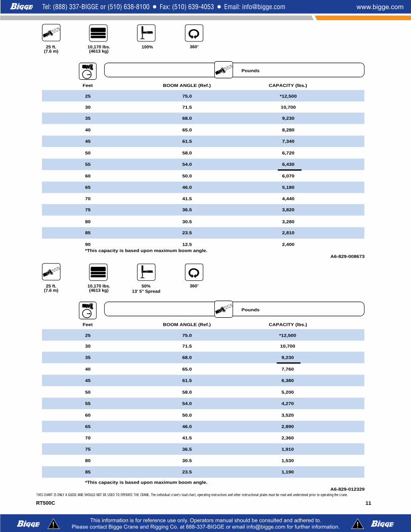
25 ft. (7.6 m)
360°
Pounds
100%10,170 lbs. (4613 kg)
25 75.0 *12,500
30 71.5 10,700
35 68.0 9,230
40 65.0 8,280
45 61.5 7,340
50 58.0 6,720
55 54.0 6,430
60 50.0 6,070
65 46.0 5,180
70 41.5 4,440
75 36.5 3,820
80 30.5 3,280
85 23.5 2,810
90 12.5 2,400
A6-829-008673
Feet BOOM ANGLE (Ref.) CAPACITY (lbs.)
*This capacity is based upon maximum boom angle.
25 ft. (7.6 m)
360°
Pounds
50% 13' 5" Spread
10,170 lbs. (4613 kg)
Feet BOOM ANGLE (Ref.) CAPACITY (lbs.)
25 75.0 *12,500
30 71.5 10,700
35 68.0 9,230
40 65.0 7,760
45 61.5 6,380
50 58.0 5,200
55 54.0 4,270
60 50.0 3,520
65 46.0 2,890
70 41.5 2,360
75 36.5 1,910
80 30.5 1,530
85
*This capacity is based upon maximum boom angle.
23.5 1,190
A6-829-012329

RT500C12
THIS CHART IS ONLY A GUIDE AND SHOULD NOT BE USED TO OPERATE THE CRANE. The individual crane's load chart, operating instructions and other instructional plates must be read and understood prior to operating the crane.
28 -70 ft. (8.5 - 21.3 m)
10,170 lbs. (4613 kg)
360°
Pounds
Feet
20.5 x 25 24 Ply
Stationary
28 34 40 46 52 58 64 70
10 26,200(64)
26,200(69)
1219,350(59.5)
19,350(65.5)
16,000(70)
15 13,200(51.5)
13,200(59.5)
13,200(65)
13,200(69)
20 7,910(36.5)
7,910(49)
7,910(57)
7,910(62)
7,910(66)
7,400(69.5)
255,060
(6)5,060(36)
5,060(47.5)
5,060(54.5)
5,060(60)
5,060(64)
5,060(67)
5,060(69.5)
30 3,600(15.5)
3,600(36.5)
3,600(46.5)
3,600(53)
3,600(58)
3,600(62)
3,600(65)
35 2,610(20)
2,610(36.5)
2,610(45.5)
2,610(51.5)
2,610(56.5)
2,610(60)
401,890(23)
1,890(36.5)
1,890(45)
1,890(50.5)
1,890(55)
451,340(25)
1,340(37)
1,340(44.5)
1,340(49.5)
50 910(26.5)
910(37)
910(43.5)
A6-829-009074
NOTE: ( ) Boom angles are in degrees.
A6-829-009460
28 34 40 46
0° 5,030(25.1)
3,360(31)
2,300(37)
1,540(43)
Boom Angle
NOTE: ( ) Reference radii are in feet.

RT500C 13
THIS CHART IS ONLY A GUIDE AND SHOULD NOT BE USED TO OPERATE THE CRANE. The individual crane's load chart, operating instructions and other instructional plates must be read and understood prior to operating the crane.
28 -70 ft. (8.5 - 21.3 m)
10,170 lbs. (4613 kg)
Defined Arc Over Front
6°
Pounds
Feet
20.5 x 25 24 Ply
Stationary
A6-829-009460
28 34 40 46
0° 9,860(25.1)
6,940(31)
5,130(37)
3,880(43)
Boom Angle 52
2,980(49)
58
2,290(55)
64
1,760(61)
70
1,350(66.6)
NOTE: ( ) Reference radii are in feet.
+-
28 34 40 46 52 58 64 70
10 28,650(64)
26,200(69)
1224,950(59.5)
24,950(65.5)
21,000(70)
15 20,900(51.5)
20,900(59.5)
20,900(65)
16,500(69)
20 14,900(36.5)
14,900(49)
14,900(57)
12,200(62)
12,200(66)
12,200(69.5)
259,900
(6)9,900(36)
9,900(47.5)
9,900(54.5)
9,400(60)
9,400(64)
9,400(67)
9,400(69.5)
30 7,350(15.5)
7,350(36.5)
7,350(46.5)
7,000(53)
7,000(58)
7,000(62)
7,000(65)
35 5,660(20)
5,660(36.5)
5,660(45.5)
5,600(51.5)
5,600(56.5)
5,600(60)
404,450(23)
4,450(36.5)
4,450(45)
4,450(50.5)
4,450(55)
453,550(25)
3,550(37)
3,550(44.5)
3,550(49.5)
50 2,850(26.5)
2,850(37)
2,850(43.5)
552,290(3.5)
2,290(28)
2,290(37)
601,840(13)
1,840(28.5)
65 1,460(15.5)
A6-829-009073A
NOTE: ( ) Boom angles are in degrees.

RT500C14
28 -70 ft. (8.5 - 21.3 m)
10,170 lbs. (4613 kg)
Boom Centered Over Front
Pounds
Feet
20.5 x 25 - 24 Ply Pick & Carry
(Up to 2.5 MPH)
A6-829-009460
28 34 40 46
0° 8,970(25.1)
6,870(31)
5,130(37)
3,880(43)
Boom Angle 52
2,980(49)
58
2,290(55)
64
1,760(61)
70
1,350(66.6)
NOTE: ( ) Reference radii are in feet.
28 34 40 46 52 58 64 70
1033,800
(64)
1229,000(59.5)
1523,600(51.5)
23,600(59.5)
23,600(65)
23,600(69)
2014,900(36.5)
14,900(49)
14,900(57)
14,900(62)
12,200(66)
12,200(69.5)
259,900
(6)9,900(36)
9,900(47.5)
9,900(54.5)
9,900(60)
9,400(64)
9,400(67)
307,180(15.5)
7,180(36.5)
7,180(46.5)
7,180(53)
7,180(58)
7,000(62)
7,000(65)
355,660(20)
5,660(36.5)
5,660(45.5)
5,660(51.5)
5,660(56.5)
5,600(60)
404,450(23)
4,450(36.5)
4,450(45)
4,450(50.5)
4,450(55)
453,550(25)
3,550(37)
3,550(44.5)
3,550(49.5)
502,850(26.5)
2,850(37)
2,850(43.5)
552,290(3.5)
2,290(28)
2,290(37)
601,840(13)
1,840(28.5)
651,460(15.5)
A6-829-009075
NOTE: ( ) Boom angles are in degrees.
THIS CHART IS ONLY A GUIDE AND SHOULD NOT BE USED TO OPERATE THE CRANE. The individual crane's load chart, operating instructions and other instructional plates must be read and understood prior to operating the crane.

RT500C 15
28 - 70 ft. (8.5 - 21.3 m)
23 ft. (7.1 m)
360°
AXIS OF ROTATION
FEET
FEET
110
100
90
80
70
60
50
40
30
20
10
0
90 80 70 60 50 40 30 20 10
75°MAX
BOOM ANGLE
0°
10°
20°
30°
40°
50°
60°
70°70
64
58
52
46
40
34
28
230°
15°30°
3'-0" 4'-6"
DIMENSIONS ARE FOR LARGEST GROVE FURNISHED HOOK BLOCK AND HEADACHE BALL, WITH ANTI-TWO BLOCK ACTIVATED.
Working range

RT500C16
23 ft. (7.1 m)
360°
Pounds
100%10,170 lbs. (4613 kg)
7512,000
(27)
7010,400 (33.3)
658,500 (40.2)
607,400 (47)
556,600 (53.2)
506,100 (59.2)
455,160 (64.7)
404,410 (69.6)
353,840 (74)
303,400 (77.8)
A6-829-008660
Main Boom Angle
Cap. in lbs. (Rad. Ref)
7,700 (32.5)7,000 (38.1)6,300 (44.9)
5,450 (51.3)5,000 (57.3)
4,700 (62.9)4,500 (68)
4,010 (72.6)3,530 (76.6)3,160 (80.1)
Cap. in lbs. (Rad. Ref)
5,070 (35.7)4,800 (41.2)4,500 (47.8)
4,300 (54)
4,100 (59.8)
3,900 (65.1)3,800 (69.9)
3,700 (74.2)3,390 (77.9)
Cap. in lbs. (Rad. Ref)
0°OFFSET
15°OFFSET
30°OFFSET
NOTE: ( ) Reference radii are in feet.
23 ft. (7.1 m)
360°
Pounds
50% 13' 5" Spread
10,170 lbs. (4613 kg)
7512,000
(27)
7010,050 (33.3)
657,580 (40.2)
605,850 (47)
554,610 (53.2)
503,680 (59.2)
453,000 (64.7)
402,490 (69.6)
352,100 (74)
301,800 (77.8)
A6-829-013238
Main Boom Angle
Cap. in lbs. (Rad. Ref)
7,700 (32.5)7,000 (38.1)6,300 (44.9)
4,950 (51.3)3,950 (57.3)
3,210 (62.9)2,650 (68)
2,220 (72.6)1,890 (76.6)1,640 (80.1)
Cap. in lbs. (Rad. Ref)
5,070 (35.7)4,800 (41.2)4,500 (47.8)
4,300 (54)
3,600 (59.8)
2,950 (65.1)2,460 (69.9)
2,090 (74.2)1,790 (77.9)
Cap. in lbs. (Rad. Ref)
0°OFFSET
15°OFFSET
30°OFFSET
NOTE: ( ) Reference radii are in feet.
THIS CHART IS ONLY A GUIDE AND SHOULD NOT BE USED TO OPERATE THE CRANE. The individual crane's load chart, operating instructions and other instructional plates must be read and understood prior to operating the crane.

Rated lifting capacities Symbols Glossary
Drive Rotation
Electrical System Suspension
Fuel Tank Capacity Tires
Engine Brakes
Outrigger Controls Axles
Outriggers Transmission
Frame Steering
Lights Boom Elevation
Cab Swing
Tele-Swingaway Hydraulic System
Jib Hoist
Boom Nose Radius
Boom Extension Boom Length
Grade Gear
Boom Counterweight
HookblockHSpeed
OilFixed Swingaway
Lattice Extension Luffing Jib
AP308Fixed10ft.Boomextension
AP308Tele.Boomextension
RT500C
NOTES FOR LIFTING CAPACITIES
WARNING: THIS CHART IS ONLY A GUIDE.The notes below are for illustration only andshould not be relied upon to operate the crane.The individual crane's load chart, operatinginstructions and other instruction plates must beread and understood prior to operating the crane.
1.All rated loads meet ANSI/ASME B30.5 Mobile andLocomotive Cranes. Testing and development wereperformed to SAEJ1063, Cantilevered Boom CraneStructures, Method of Test and SAEJ765 Crane StabilityTest Code.
2. Rated loads include the weight of hookblock, slingsand auxiliary lifting devices and their weights shall besubtracted from the listed rating to obtain the net loadto be lifted. When more than the minimum requiredhoist reeving is used, the additional rope weight shallbe considered part of the load to be handled.
3. Capacities appearing above the bold line are basedon structural strength.Tipping should never be reliedupon as a capacity indication.
4.The machine shall be leveled on a firm supportingsurface. Depending on the nature of the supportingsurface, it may be necessary to have structural supportsunder the outrigger floats or tires to spread the load toa larger bearing surface.
5.When either boom length or radius or both arebetween values listed, the smallest load shown at eitherthe next larger radius or next longer or shorter boomlength shall be used.
6.Tires shall be inflated to the recommended pressurebefore lifting on rubber.
7. For outrigger operation, outriggers shall beproperly extended with tires raised free of craneweight before operating the boom or lifting loads.

Distributed By:
Constant improvement and engineering progress make it necessary that we reserve the right to makespecification, equipment, and price changes without notice. Illustrations shown may include optionalequipment and accessories and may not include all standard equipment.
Form No.: SBRT500C Part No.: 3-484 1197-10M Printed in U.S.A.
Grove Worldwide – World HeadquartersGrove North America1565 Buchanan Trail East P.O. Box 21 Shady Grove, Pennsylvania 17256, U.S.A.Tel: [Int + 1] (717) 597-8121Fax: [Int + 1] (717) 597-4062Western Hemisphere, Asia/Pacific
Grove Europe Limited* Sunderland SR4 6TT, England Tel: [Int + 44] 191 565-6281Fax: [Int + 44] 191 564-0442Europe, Africa, Middle East
Grove Europe Limited*P.O. Box No. 2684A Kimber RoadAbingdon, Oxfordshire, 0X141SGTel: [Int + 44] 1235 55-3184Fax: [Int + 44] 1235 55-3218*Grove Europe Limited, Registered in England,
Number 1845128, Registered office, Crown Works,
Pallion, Sunderland, Tyne & Wear, England SR4 6TT
Deutsche Grove GmbHSales and Service Helmholtzstrasse 12, Postfach 5026D-40750 Langenfeld, GermanyTel: [Int + 49] (2173) 8909-0Fax: [Int + 49] (2173) 8909-30
Wilhelmshaven WorksIndustriegelande West, Postfach 1853D-26358 Wilhelmshaven, Germany Tel: [Int + 49] (4421) 294-0Fax: [Int + 49] (4421) 294-301
Grove France S.A. 16, chaussée Jules-César, 95520 OSNYB.P. 203, 95523 CERGY PONTOISE CEDEXFranceTel: [Int + 33] (1) 30313150Int: [Int + 33] (1) 30386085
Grove Asia/Pacific - Regional Office 171 Chin Swee Road#06-01 San Centre Singapore 0316Tel: [Int + 65] 536-6112 Fax: [Int + 65] 536-6119 Asia/Pacific, Near East
Grove China - Representative OfficeBeijing Suite 6074No. 33 East Chang An Avenue Beijing, 100004, China Tel: [Int + 86] (10) 513-7766Fax: [Int + 86] (10) 513-7307
Grove Product Support Western Hemisphere, Asia/Pacific1086 Wayne AvenueChambersburg, Pennsylvania USATel: [Int + 1] (717) 263-5100Fax: [Int + 1] (717) 267-0404
Europe, Africa, Middle EastSunderland SR4 6TT, EnglandTel: [Int + 44] 191 565-6281Parts Fax: [Int + 44] 191 510-9242Service Fax: [Int + 44] 191 510-9560
http://www.groveworldwide.com