DIGITALDIVERT CONTROLSYSTEM DD-23 - K-Patents4 2.3.1Overview Red indicator lights (alarms) Yellow...
50
PROCESS INSTRUMENTS DIGITAL DIVERT CONTROL SYSTEM DD-23 INSTRUCTION MANUAL IM-EN-DD23 Rev. 1.43
Transcript of DIGITALDIVERT CONTROLSYSTEM DD-23 - K-Patents4 2.3.1Overview Red indicator lights (alarms) Yellow...

PROCESS INSTRUMENTS
DIGITAL DIVERTCONTROL SYSTEMDD-23
INSTRUCTIONMANUAL
IM-EN-DD23 Rev 143
INSTRUCTION MANUALFOR DD-23
WARNING
The process medium may be hot or otherwise hazardous Precautions when
removing the sensor from the process line
Make sure that the process line is not under pressure Open a vent valve to the
atmosphere For a retractorisolation valve the line pressure should be within
specifications
For a prism wash system close a hand valve for the wash medium and disable the
wash valve Loosen the clamp or flange bolts cautiously be prepared to tighten again
Be out of the way of any possible splash and ensure the possibility of escape
Use shields and protective clothing adequate for the process medium Do not rely on
avoidance of contact with the process medium After removal of the sensor it may be
necessary to mount a blind flange for security reasons
DocumentRevision No 143 Effective May 15 2016
This product manual is delivered to the end-user with a K-Patents product Information in this manual
is subject to change without notice The latest manual version is always available in the Downloads
section at httpwwwkpatentscom You can also contact manualskpatentscom
K-PATENTS OY K-PATENTS OY K-PATENTS INC
Postal address Street address 1804 Centre Point CirclePO Box 77 Elannontie 5 Suite 106FI-01511 Vantaa Finland FI-01510 Vantaa Finland Naperville IL 60563Tel + 358 207 291 570 Tel +1-630-955 1545Fax +358 207 291 577 Fax +1-630-955 1585infokpatentscom infokpatents-usacomhttpwwwkpatentscom httpwwwkpatentscom
Table of contents
1 Introduction 1
11 Warranty 1
12 Disposal 1
2 The Divert Control System DD-23 3
21 Overview 3
22 Divert Control Unit 3
23 Operator panel 3
231 Overview 4
232 Green indicator lights System ok 5
233 Yellow indicator lights Warnings 5
234 Red indicator lights Alarms 5
235 White pushbuttons Testing and resetting 5
236 Header wash key Enabling ring header wash 6
237 Emergency divert button Manual divert 6
238 External emergency divert button 6
24 Prism wash 6
25 Indicating transmitters 6
3 Mounting 7
31 Mounting prism wash 7
32 Wiring 8
321 Relays 8
33 Switch inputs 10
331 External Divert switchpush button - input J8 10
332 External divert reset button - input J9 10
333 Header wash key - input J10 10
34 Remote ethernet connection 12
4 Startup 13
41 Divert system pre-startup checklist 13
42 Divert control unit DD-23 startup 14
5 Configuration 15
51 Calibration lock 15
52 Divert decision rules 16
53 Refractometer concentration measurement 17
54 Refractometer activation for divert control 18
55 Signal difference alarm 18
56 Low alarms 19
561 Solids warning 19
562 Solids alarm 19
57 Refractometer malfunction alarm 19
58 Prism wash 19
6 Regular maintenance and troubleshooting 21
61 Information flow 21
62 Malfunctions 21
63 Diagnostic tools 23
64 Troubleshooting 23
641 A question mark () on the refractometer display 23
642 A refractometer refuses to come on-line 23
643 No lights come up in the Divert Control Unit 24
644 All lights are blinking 24
65 Ethernet strain relief for transmitters 24
7 Divert control logics 27
71 Safety decision logic 27
72 Divert decision logic 28
73 In operation logic 29
74 Malfunction logic 30
75 Resettable alarm logic 31
76 Refractometer difference logic 32
77 Wash arbitration logic 33
78 Wash check logic 34
8 Remote control interface 35
81 Divert Control Unit IP address 35
82 The remote interface 35
821 Main page 35
822 Instrument pages 36
823 Diagnostics page 36
824 Log page 37
825 Parameters page 38
83 Data logging 38
9 DD-23 specifications 39
91 Divert Control Unit specifications 39
92 Divert control unit spare parts 40
A Index 41
1
1 Introduction
The K-Patents Digital Black Liquor Divert Control SystemDD-23 provides a divert sig-
nal preventingblack liquorwithdangerously lowsolids to reach theblack liquor burn-
ers The system is built strictly according to the principles of Recommended Good
Practice Safe Firing of Black Liquor in Black Liquor Recovery Boilers (BLRBAC April
2015 the document is available at
httpblrbacorgsitesdefaultfilesSafe20Firing20of20Black20Liquor20-20April202015pdf)
The system consists of the following parts Two K-Patents Process refractometers
PR-23-SD (A amp B) are installed in series in the main black liquor line Each refrac-
tometer is complete with a sensor an Indicating transmitter and interconnecting ca-
bles Each refractometer provides also two 4ndash20 mA output signal not used by the
divert control system These can be used to give solids output or temperature out-
put signals The sensors are also equipped with a steam wash nozzles although the
self-cleaning sensor design may eliminate the need for prism wash altogether
11 Warranty
K-Patents warrants that all products made by K-Patents shall be free of defects in ma-
terial and workmanship K-Patents agrees to either replace or repair free of charge
any such product or part thereof which shall be returned to the nearest authorized
K-Patents repair facility within two (2) years from the date of delivery
Before returning a defective product for service or replacement please contact K-Pa-
tents or your nearest K-Patents representative (see httpwwwkpatentscom for
contact information) For the health and safety of personnel handling your return
clean the instrument especially the parts that have been in contact with the process
liquid before packing it Ship the cleaned instrument to the address given to you
12 Disposal
When disposing of an obsolete instrument or any parts of an instrument please ob-
serve the local and national requirements for the disposal of electrical and electronic
equipment The aluminium or stainless steel sensor housing can be recycled with
other metallic waste of the same type
2
Figure 11 Complete Digital Black Liquor Divert Control System DD-23
3
2 The Divert Control System DD-23
21 Overview
The Divert control system DD-23 includes
minus A Divert Control Unit
minus Two PR-23-SD refractometer sensors
minus Two isolation valves SDI for the sensors above to allow removal of the refractome-
ters from a pipe with full 983405low and pressure The isolation valve includes a prism
wash nozzle and two check valves (one for prismwash one for stuf983405ing box 983405lush)
minus A roofed mounting plate to mount the two Indicating transmitters and the Divert
Control Unit together
minus Wiring to connect the Indicating transmitters with the Divert Control Unit
minus Two steam valves with steam traps for prismwash (pneumatic + solenoid valves)
minus Two hand valves (one for prism wash one for stuf983405ing box 983405lush)
minus A remote operator panel facility accessible with a web browser over Ethernet
BLRBAC (The Black Liquor Recovery Boiler Advisory Committee) recommends a
spare refractometer sensor to be maintained in stock on-site
The system can also be used with two PR-21-S process refractometers if installation
of or upgrade to PR-23-SD sensors is unfeasible Both sensor require their own indi-
cating transmitters and the required interconnecting cables between the sensor and
transmitter but otherwise the installation is similar to the PR-23-SD based one
22 Divert Control Unit
The Divert Control Unit is contained in an enclosure with the same dimensions as the
refractometer transmitter enclosure The control unit includes
minus An operator with system state indicators and pushbuttons
minus Relay outputs for connecting to the control system
minus Contact inputs for external control
minus Ethernet interface for remote operator panel
23 Operator panel
The operator panel has a clear layout and the operator can see all information at one
glance The divert decision is controlled from the operator panel which provides dou-
bled security since information is shown both as LED indication in the Divert control
unit and as a diagnostic messages in the Indicating transmitters The same informa-
tion is also available through the remote operator panel
4
231 Overview
Red indicatorlights (alarms)
Yellow indicatorlights (warnings)
Green indicatorlights (all well)
White push-buttons
Red push-button
Figure 21 DD-23 operator panel
The three top rows on the operator panel consist of indicator lights The green A IN
OPERATION and B IN OPERATION lights are also push buttons used to include the refrac-
tometers in theDivert system Below the lights there are push buttons and theHEADER
WASH key key used to operate the system
The indicator lights on the operator panel are arranged like traf983405ic lights top row is
red for alarm middle row is yellow for warning and bottom row is green for system
ok When the system is running normally only the row of green lights should be lit
The white LIGHT TEST button is used to check that all the LEDs behind the indicator
lights are working It also veri983405ies the data processing system in the control unit The
other two white push buttons ALARM RESET and DIVERT RESET can be used to reset
the system back to normal after all problems have been 983410ixed The HEADER WASH key
enables the use of ring header washing with water when set to ON
The big red EMERGENCY DIVERT push button is used to manually initiate divert in an
emergency situation An external push button can also be connected to a switch input
in the control unit as External Emergency divert button see Section 238
5
232 Green indicator lights System ok
Each refractometer has a green operating light ndash A IN OPERATION and B IN OPERATION ndash
to let the operator know when he can rely on the refractometer measurement A re-
fractometer will only in983405luence the divert decision and activate warnings and alarms
when it is in divert operation ie when its green operating light is lit
When DIVERT is effective the system may be reset to normal operation only when
SAFE SOLIDS is lit
233 Yellow indicator lights Warnings
The SOLIDS WARNING light indicates a black liquor concentration of below warning
limit (by default at 60) This warning can be activated by either refractometer
The AampB DIFFERENCE light is lit when the refractometer readings differ by at least 2
This warning will only be initiated if both refractometers are operating
If the yellow MALFUNCTION light is switched on some part of the system ndash a refrac-
tometer an indicating transmitter or the control unit ndash is malfunctioning A list over
malfunctions and critical malfunctions is given in Section 62 If a critical malfunction
occurs in a sensor or transmitter the malfunctioning refractometer will be automat-
ically removed from divert operation (its operating light will also be switched off)
Check the reason for the malfunction and correct the problem (see Section 64) be-
fore returning the refractometer back to divert operation
234 Red indicator lights Alarms
The black liquor SOLIDS ALARM is lit when the concentration reading goes below alarm
limit (by default below 58) This alarm can be activated by either refractometer
depending on the operation rule setting
The DIVERT light will be switched on when the SOLIDS ALARM is activated The DIVERT
light indicates divert status of the divert relay The relay is inactive in the divert posi-
tion because then a power failure will give a divert decision signal to the system
The OVERRIDE light is lit to indicate that no automatic divert will happen as long as
the system is in the header wash state (see Section 236)
235 White pushbuttons Testing and resetting
The LIGHT TEST button switches all 12 lights on The ALARM RESET button resets the
alarm lights
6
236 Header wash key Enabling ring header wash
The header wash key function is a 3-level procedure which can be used when ring
header washing with water is needed When the HEADER WASH key is switched to ON
position and information fromblack liquor guns switch inputs connected in series tell
that guns are out from recovery boiler then a ring header wash can be done without
activating Divert
Pushing the EMERGENCY DIVERT button will always initiate divert regardless of the
header wash functionality
237 Emergency divert button Manual divert
The EMERGENCY DIVERT push-button is used to manually initiate divert in an emer-
gency situation
238 External emergency divert button
An external (remote) push button can also be connected to an input inside the Control
unit see Figure 33
External emergency divert button must be normally closed (NC) Opening the circuit
will initiate divert
24 Prism wash
The wash parameters for the sensors are set through each transmitter (Section 24)
The transmitters contain a relay for prismwash To follow the BLRBAC recommenda-
tion not to wash both prisms at the same time the Divert Control Unit implements an
interlock which prevents the instrument from washing both sensors simultaneously
25 Indicating transmitters
Mechanically the Indicating transmitters shipped with a DD-23 are the same than
PR-23 Indicating transmitter DTR The transmitter will only allow single sensor con-
nection and a special DD-23 transmitter software is used for the Divert system When
Divert software is 201 or newer Indicating transmitter software version has to be
412 or newer
For more information on the basic functions of an indicating transmitter please see
the PR-23 manual chapters 3 and 10
7
3 Mounting
For mounting of the process refractometers and the isolation valves consult the sep-
arate process refractometer PR-23 instruction manual
Figure 31 Mounting the Divert control system
31 Mounting prism wash
K-Patents recommends to use a steam trap instead of a preconditioning valve to re-
move condensate from the steam line
8
32 Wiring
For wiring for complete system see Figure 32 which shows the connections to the
Indicating transmitters and to steam washing Figure 33 has information of all con-
nections to the Divert control unit
Figure 32 Transmitter wiring cables and connections
321 Relays
Relay 1 NORMALDIVERT information
Relay 2 NORMALDIVERT information
Relay 3 SOLIDS WARNING when one of the refractometers goes lower than the
solids warning limit typically 60 or higher See Section 561
Relay 4 SOLIDS ALARMwhen one of the refractometers goes lower than the solids
alarm limit typically 58 or higher See Section 562
Relay 5 Refractometer signal differencewarning when the refractometer readings
have more than 2 difference in concentration See Section 55
Relay 6 Horn relay connection to the audible alarm See Section 75
Relay 7 Header wash key information See Section 333
Relay 8 Refractometer A malfunction information See Sections 62 and 74
Relay 9 Refractometer B malfunction information See Sections 62 and 74
Relay 10 Information on if refractometer A is active in the Divert Control System or
dropped off
Relay 11 Information on if refractomter B is active in the Divert Control System or
dropped off
9
Figure 33 Divert control unit internal wiring
10
33 Switch inputs
331 External Divert switchpush button - input J8
An external divert switch can be connected to the DD-23 Divert Control Unit input J8
If the external divert switch is not used a jumper has to be connected across J8 The
unit is delivered with this jumper connected
332 External divert reset button - input J9
If youwant to use external Divert reset button it can be connectedmax 200m(600 ft)
from the DD-23 Divert control unit Use normal instrument cable 2x05 (AWG 20) and
connect cable to DD-23 motherboard input J9
You must make sure both refractometers A and B are working OK before starting to
use the remote divert button (the remote interface can be used to check on the refrac-
tometers see Chapter 8)
The external reset button connection is normally open (NO)
333 Header wash key - input J10
Black liquor is injected to the recovery boiler through liquor guns Occassionally the
header ring needs washing and during that procedure the divert system has to be by-
passed and the liquor guns have to be removed from the furnace The Digital Divert
Control System DD-23 allows for a safe override of divert logic during header ring
wash
The override ismounted by connecting the gunmicro switches in series to the Header
washoverride key switch input J10 see Figure 35
TheHeaderwash keymaybe usedwithout the external switch information if a jumper
(dotted line in Figure 35) is placed to swith input J10 If the input is left open the key
does not have any effect
11
DD-23Operator panel
OVERRIDEHEADER WASH
HEADERWASHKEY
MICROSWITCHon each liquor gun oron liquor gun door
Recoveryboiler
Figure 34 Header wash key functionality
Guns out microswitches
HEADERWASHKEY
SWITCH INPUTJ10
Figure 35 Header wash key connections
12
34 Remote ethernet connection
The ethernet connection for the Divert user interface DI and data logging purposes is
an 8-pin M12 connector at the bottom of the Divert Unit The ethernet cable PR-8430
to DI can be connected while the unit is powered without opening the case Ethernet
converter cable PR-8663 is used when a computer or other device with RJ45 connec-
tor is connected with the DD-23
The remoteethernet connection
Figure 36 Ethernet connection
13
4 Startup
41 Divert system pre-startup checklist
1 SDI Isolation valves mounted correctly
a Vertical pipe MTG453
b Horizontal pipe MTG471
2 DD-23 control unit installed DIM243 Figure 91 on page 39
3 Pressure reducing valve solenoid valve steam trap installed and connected to the
prism wash nozzle on each sensor
a Steam pipes for black liquor MTG470
b Nozzle MTG482
4 9ndash15 bar (130ndash220 psi) steam connected to the solenoid valve on each sensor
5 Instrumentation air 4ndash6 bar (60ndash90 psi) connect to the solenoid valve on each
sensor
6 Power supply (230110Vac24Vdc) connected SYS358Figure 31 on page 7 and
WRG366 Figure 31 on page 7
a Transmitter A
b Transmitter B
c Divert control unit
d Solenoid valve A
e Solenoid valve B
7 Cables connected SYS358Figure 31 on page 7 WRG366 Figure 31 on page 7
a Transmitter A to sensor A
b Transmitter B to sensor B
c Transmitter A to solenoid valve A
d Transmitter B to solenoid valve B
e Relay information from the Divert control unit to your control system or the
Divert valve
f Transmitter A mA output to your control system
g Transmitter B mA output to your control system
h Ethernet to your control system (optional)
14
42 Divert control unit DD-23 startup
For the refractometer startup consult Chapter 5 in the separate Process refractometer
PR-23 manual
1 Check the wiring and supply voltage
Before the power is switched on the divert output relay rsquonormal operationrsquo is in
divert position
2 Connect the mains power to start the system
There are no power switches in the instruments They are always On when the
mains power is connected
3 While the Control unit is powering up the DIVERT and SOLIDS ALARM lights are both
blinking When the unit is fully functional it is in the divert mode the DIVERT light
is on and the SOLIDS ALARM light is blinking
4 Press the LIGHT TEST button on the Divert control unit All 12 lights should switch
on
5 Reset the solids alarm by pressing the ALARM RESET button
The indicator stops blinking and should stay on
6 Each indicating transmitter should now state refractometer letter either a or b in
the upper left corner of the transmitter display If therersquos a question mark instead
of a letter on either of the transmitters see Chapter 6
If the process pipe is full the message for each refractometer should be NORMAL
OPERATION if process pipe is still empty message will be NO SAMPLE
Now activate refractometer A into the Divert by pushing the button A IN OPERATION
on the Divert control unit panel The button lights up and on the transmitter dis-
play the refractometer letter changes to capital A Then activate refractometer B
similarly by pushing the button B IN OPERATION
If the green IN OPERATION light blinks the refractometer in question is perform-
ing wash The refractometer will automatically come into operation after it has
983405inished washing
7 Now the Divert control system DD-23 is set for normal monitoring operation
8 When black liquor is in the line check that the prism wash is working for each
refractometer First press soft keyMENU on the transmitter keyboard then choose
3 SYSTEM STATUS to get to the system status display Now press soft key WASH to
initiate manual wash follow the optical image and check that it changes during
the steam wash If wash was successful wait until message is NORMAL OPERATION
and then proceed with startup If wash doesnrsquot seem to work see Chapter 6
9 If the three green lights on the third row are all on and all conditions for safe boiler
operation are satis983405ied turn off diversion by pressing the DIVERT RESET button All
warning lights are now turned off and only the 3 green lights are on
15
5 Configuration
The K-Patents Divert control system is shipped fully calibrated by the manufacturer
This chapter contains instructions on how to make 983405ine adjustments of the system
51 Calibration lock
Parameter changes are possible only when the calibration lock is open The calibra-
tion lock can be closed by a switch inside the control unit cover (see Figure 51) When
the lock is open a red led is illuminated next to the lock switch For safety reasons
keep the calibration lock open only during parameter changes done through the web
interface (see Chapter 8)
CALIBRATIONLOCK
CALIBRATIONLOCK
Figure 51 Location of the calibration lock
16
52 Divert decision rules
Two refractometers in operation
BLRBAC states the following For the solids measurements two refractometers in se-
ries must be used When both refractometers are in service the requirement for an au-
tomatic black liquor diversion can be satis983410ied by either of the following options
1 If either refractometer reads dissolved solids content 58 (default) or below
an automatic black liquor diversion must take place
2 When both refractometers read dissolved solids content 58 (default) or be-
low an automatic black liquor diversion must take place
Either option is satisfactory
The rules are listed in decreasing order of security Only rule 1 satis983405ies the high safety
requirements set by BLRBAC August 1982 On the other hand the probability of false
trips decreases with decreasing safety It means that if false trips are too frequent the
rule 2 may be preferred at the cost of safety The rule 2 has later been accepted by
BLRBAC
The divert decision rule is selected by the rule switch inside the divert control unit
cover (Figure 51) The state of the switch is indicated by a yellow indicator LED for
rule 2 and a green one for rule 1
Rule switch Rule
1-of-2 Rule 1
2-of-2 Rule 2
Table 51 Divert decision rule selection
The logical description of the safety decision logics is given Tables 53 and 52 below
A
B
under 58 over 58
under 58 divert divert
over 58 divert safe
Table 52 Two instruments in operation rule 1-of-2
A
B
under 58 over 58
under 58 divert unsafe
over 58 unsafe safe
Table 53 Two instruments in operation rule 2-of-2
17
Only one refractometer in operation
When only one instrument is in operation the divert action takes place if this instru-
ment reads 58 or below The rule selection has no in983405luence on the divert decision
in this case
A or B
under 58 unsafe
over 58 safe
Table 54 Operation logic when only one instrument operating
No refractometer in operation
If both instruments are out of operation (due to malfunction or maintenance) then
according to BLRBAC divert action must take place
Emergency divert
In all cases the systemmay be set to DIVERT by pressing the EMERGENCY DIVERT button
(or an external emergency divert button see Section 238)
53 Refractometer concentration measurement
For refractometer calibration consult also Chapter 6 in the separate Process refrac-
tometer PR-23 Instruction manual
The CONC displays of the two indicating transmitters have to show the same value
within 05 If there is a difference this can be eliminated by adjusting the bias for
one of the refractomers comparison with sample determination can decide which
one should be corrected
In the PR-23 refractometer system bias is the parameter F00 the third parameter in
the 983405ield adjustment parameter list To change it 983405irst press the MENU soft key then
5 CALIBRATION then 1 CHEMICALamp FIELD PARAMETERS and then 2 FIELD CALIBRATIONPARA-
METERS Choose 3 F00 (BIAS) to change the bias (see Section 625 in the PR-23manual)
If the Indicating transmitter A displays 682 and B displays 688 the difference can
be eliminated by lowering B by 06 This is done by setting the 983405ield calibration
parameter F00 to -06 in Indicating transmitter B
Due to its digital measurement principle the readings of the K-Patents Process refrac-
tometer do not drift by time Frequent recalibrations based on of983405linemoisture analy-
sis must be avoided as they will introduce random 983405luctuations to the refractometer
readings
18
54 Refractometer activation for divert control
When a refractometer is activated for Divert control the upper left corner of the trans-
mitter display shows alternatively A a B b or If the corner is blank the instrument
is not suitable for divert operation
Transmitter A in
Divert operation
Transmitter B not
in Divert operation
Ethernet connection failure
Figure 52 Indicating transmitters (STR) activated to Divert control
The decision to display A (a) or alternatively B (b) depends on the IP address settings
in the transmitter The IP address of instrument A is 17216232 and that of instru-
ment B is 17216233 These addresses have been set in the factory and should not be
changed (See Chapter 8 for information on system IP address and connecting to the
DD-23 system)
If a question mark appears on the transmitter display the reason is usually that the
Ethernet cable between the transmitter and the Control unit is not properly connected
or theDivert control unit is not powered on Reconnect (or replace cable if necessary)
to 983405ix
The refractometer program version has to be 300 or higher to have divert system
functionality Divert version 201 or higher requires DTR software version 412 or
higher Also the refractometer has to have the correct software parameters to be used
in a divert control system In order to convert a stand-alone refractometer into one
used on the Divert control system please contact K-Patents The easiest way to check
if a refractometer is con983405igured for DD-23 use is to look at the main display If the
aAbB letter is present (see Figure 52) the instrument may be used in the Divert
control system
If a DD-23 activated transmitter is used in another type of application the divert func-
tion has to be deactivated by K-Patents
55 Signal difference alarm
According to BLRBAC if a difference of 2 in solids (absolute value) or greater exists
between refractometer readings an alarm shall be activated
The alarm limit of 2 is the maximum difference The limit can be changed into a
smaller number through the remote interface see Chapter 8
19
56 Low alarms
561 Solids warning
If the concentration reading of either refractometer falls below this limit (60 by de-
fault) thewarning is activated The limit canbe changed through the remote interface
see Section 825
Minimum low warning level is 60 according to BLRBAC
562 Solids alarm
If the concentration reading of either refractometer falls below this limit (58 by de-
fault) the alarm is activated The limit can be changed through the remote interface
see Chapter 8
Minimum low alarm level is 58 according to BLRBAC
57 Refractometer malfunction alarm
The built-in intelligent diagnostics of a K-Patents Process refractometer provide a
tight control of the operation A full test cycle is completedwith an interval of less than
one second For details consult the Process refractometer PR-23 instruction manual
Not all malfunctions cause the instrument to be removed from the Divert control sys-
tem However all malfunction alarms need to be checked see Section 62 for more
information
58 Prism wash
Even though the sensors are equipped with a steam wash facility it is not necessarily
needed For K-Patents Process Refractometer the need of prism wash is reduced and
even in some cases eliminated
However an automatic regular prism wash provides an ef983405icient check that the re-
fractometer reacts A steam wash of 3 seconds every half hour should be suf983405icient
Only one instrument is washing at a time and during the wash the system acts in the
single-instrument mode
To change wash times or relay con983405igurations consult the PR-23 process refractome-
ter system manual sections 613 Con983410iguring relays and 631 Setting prism wash
parameters
20
The recommended wash pressures and times are given in the table below
Wash parameters for Safe-Drivetrade Isolation valve nozzle SDI
Minimum above
process pressure
Maximum above
process pressure
Wash
time
Reco-
very
Interval
Steam (SN) 5 bar (70 psi) 8 bar (115 psi) 3ndash5 s 20ndash30 s 20ndash30 min
Do not exceed the recommended wash times because some process media may burn
to the prism surface if steamed for longer time In case of coating shorten the wash
interval
It should be noted that if wash check is enabled on the instrument it can cause the
instrument to be taken out of divert use if during the set wash tolerance time nowash
cycles have been noted as successful This can cause a divert if both instruments fail
wash checks in sequence
21
6 Regular maintenance and troubleshooting
As theDivert control system is apuredigital system no specialmaintenance is needed
The LIGHT TEST button on the operator panel (Figure 21) sends a signal to the micro-
processor and the microprocessor switches all 12 LED lights on as long as the button
is pressed This way not only the lights but also the processing system is checked
To assist the identi983405ication of a faulty component the information 983405low is given in Sec-
tion 61 Also the logic diagrams of Chapter 7 may be of help
61 Information flow
The divert control unit is connected to the refractometers through an Ethernet con-
nection The Control system asks for the measurement data from the instruments
several times each second Based on the data received the divert operation decisions
are made
Each refractometer performs its measurement functions independently The instru-
ments also have their own internal diagnostics which are used in the divert decision
logic as well (see Section 62)
As the Divert Control System requests information several times a second all commu-
nication problems are found immediately In case one of the refractometers does not
respond to the control unit the non-responding instrument is dropped from opera-
tion and the malfunction alarm is set
An important information when troubleshooting communication problems is the let-
ter on the upper left corner of each refractometer (see Figure 52) If the instrument
has not received any data requests from theDivert Control Unit during the last second
the letter turns into a question mark () If the letter is aAbB then the communica-
tion link between the Divert control unit and the instrument is fully functional
62 Malfunctions
If the Divert Control Unit cannot communicate with a refractometer or if the inter-
nal diagnostics of a refractometer indicate a measurement problem the Malfunction
indicator (see Figure 21) is illuminated and the corresponding relay 8 or 9 (see Fig-
ure 33) is activated
The diagnostic message of the refractometer can be seen on the transmitter screen
(see Figure 51) Some of these messages eg PRISM WASH are only informative and
do not indicate a measurement problem Table 61 below summarizes all diagnostic
messages and their effect on the Divert control system operation
22
If themalfunction is severe enough tomake themeasurement result unreliable
the refractometer cannot be used in making the divert decision In that case the
instrument is dropped from the Divert Control System and cannot be taken on-line
manually until the problem is 983405ixed
Formore information on possible causes of each error see the PR-23 instructionman-
ual Chapter 8
Message Instrument will be
dropped from the
Divert Control System
EXTERNAL HOLD
EXTERNAL WASH STOP
HIGH SENSOR HUMIDITY
HIGH SENSOR TEMP
HIGH TRANSMITTER TEMP
LOW IMAGE QUALITY X
LOW TEMP WASH STOP
LOW TRANSMITTER VOLT
NO OPTICAL IMAGE X
NO SAMPLE X
NO SAMPLEWASH STOP
NO SENSOR X
NO SIGNAL X
NORMAL OPERATION
OUTSIDE LIGHT ERROR X
OUTSIDE LIGHT TO PRISM X
PRECONDITIONING
PRISM COATED X
PRISMWASH
PRISMWASH FAILURE X
PRISMWASH WARNING
RECOVERING
SHORT-CIRCUIT X
STARTING UP X
TEMP MEASUREMENT FAULT X
Table 61 Diagnostic messages and their effect on Divert operation
23
63 Diagnostic tools
In order to make troubleshooting easier there are several built-in diagnostic tools
An event log is built in the system A short log showing last 6 events can be accessed
from the transmitter main display by pressing the soft key DD23 A more complete
event log can be found in the web-based remote interface (see Section 824)
Figure 61 Transmitter log page for instrument A
The remote interface also provides a diagnostic page which gives full information on
the system state (concentrations relay state switch state indicator state) see Sec-
tion 823
64 Troubleshooting
641 A question mark () on the refractometer display
Cause The refractometer does not receive information request packets from the Di-
vert Control Unit This may be caused by a faulty cable faulty parameters or equip-
ment malfunction either in the refractometer or in the Divert Control Unit
Action If the instrument has never been functional or if it is possible someone has
changed the instrument parameters there may be a con983405iguration problem with the
IP addresses The IP address in the refractometer should be set as given in Section 54
If possible cross-check the addresses from the diagnostic web page
Aphysical problemcanbe ruledout by looking at a small LEDclose to the transmitterrsquos
Ethernet connector If the LED is green the cable is ok Oneway to isolate the problem
is to swap the cables between the refractometers A standard Ethernet cable can be
used as a troubleshooting aid (either straight-through or cross-over)
642 A refractometer refuses to come on-line
Cause Either there is no communication to the refractometer or there is a malfunc-
tionon the refractometer It is alsopossible the transmitter is not con983405igured forDivert
use
24
Action Check that there is aAbB on the refractometer display If there is a question
mark () instead see above
Check that there is a soft key DD23 on the refractometer main display (see Figure 62
below) If the soft key is not present in the main display the instrument is not con983405ig-
ured for Divert use If this is the case please contact K-Patents
In other cases check the diagnostic message on the refractometer screen (see Sec-
tion 62)
Figure 62 Transmitter main display instrument in Divert use
643 No lights come up in the Divert Control Unit
Cause There is no power on the instrument or there is a hardware fault
Action Check that the instrument receives power In normal operation several relays
have their associated LEDs lit If there are any LEDs lit in the Divert Control Unit the
unit receives power
644 All lights are blinking
Cause There is an unrecoverable hardware fault in the Divert Control Unit
Action Please contact K-Patents
65 Ethernet strain relief for transmitters
When transmitter door is opened the ethernet cable connecting the transmitter to
the Divert Unit may come off This can be 983405ixed bymounting a strain relief plate in the
transmitter
25
1 First screw on the strain relief plate
2 Fasten the ethernet cable to the relief plate with cable ties
3 Cut the ends of the cable ties
1
2
3
Figure 63 Mounting the strain relief
26
27
7 Divert control logics
A logical description of the system is provided to complement the operational descrip-
tion given in the previous chapters
71 Safety decision logic
The core of the Divert control system is the safety decision logic which makes the
ultimate decision whether the black liquor can be safely fed to the burner or not
The logic is described in the 983405low diagram in Figure 71 The factors affecting the de-
cision are the number of instruments in operation (none one or two) and their mea-
surement results Also the selected divert rule is taken into account when two instru-
ments are in operation For a description of different rules see Section 52
As a result of this logic the system is either in SAFE SOLIDS or UNSAFE SOLIDS state
When the system is in the SAFE SOLIDS state the SAFE SOLIDS light is illuminated
no
no no
no
yes
UNSAFE SOLIDSSAFE SOLIDS
NO INSTRU-MENTS
Rule 2-of-2
2 instrumentsavailable
1 instrumentavailable
Both ge 58
Either ge 58CONC ge58
yes
yesyes
yes
no
Rule 1-of-2yes
no
DIVERT
Figure 71 Safe solids decision logic
One instrument available maymean that only one instrument is in operation or that
both instruments are in operation but one of them is washing when queried
28
72 Divert decision logic
After the system has evaluated the solid contents to be either safe or unsafe (see Sec-
tion 71) it decides whether the the system should be in the DIVERT state This deci-
sion is made according to the 983405low diagram in Figure 72
Thedefault state of the system is theDIVERTstate It canbe changed to theNODIVERT
state only by manually pressing the DIVERT RESET push-button when the solid content
is suf983405icient (SAFE SOLIDS) If the solid content drops to UNSAFE the system drops
into the DIVERT state
The only exception to this is when the HEADERWASH is active In that case the solid
content checking is skipped The system may then be switched between the DIVERT
and NO DIVERT states by using the EMERGENCY DIVERT and DIVERT RESET push buttons
in the operator panel (or the equivalent external emergency divert and divert reset
buttons)
The system will drop to the DIVERT state in all cases when the EMERGENCY DIVERT
button (or its external counterpart) is pressed
NO DIVERT DIVERT
HEADER WASH active
Divert fromsafe solids logic
EMERGENCYDIVERTpressed
DIVERT RESET pressed
yes
no
yes
no
yes
no
no
yes
Figure 72 The divert decision logics
29
73 In operation logic
IN OPERATIONbutton pressed
yes
yes
yes
yes
no
no
wash done
no
no
no
Onlyinstrument
Washing
IN OPER pressed
Critical malfunction
WAIT(LIGHT BLINKING)
IN OPERATION(LIGHT ON RELAYS
10 11 ACTIVE)
Criticalmalfunction
NOT IN OPERATION(LIGHT OFF)
yes
Figure 73 Operation logic
Whether an instrument is in op-
eration depends on the opera-
torrsquos commands and the instru-
mentrsquos diagnostics The decision
is carried out as outlined in Fig-
ure 73
An instrument can be in one of
three different states IN OPER-
ATION NOT IN OPERATION and
WAITWhen the instrument is IN
OPERATION it is used in decid-
ing whether the solid content is
in the safe level (see Section 71)
When the instrument is NOT IN
OPERATION or WAIT states it is
not used
The WAIT state occurs when the
operator has requested the in-
strument to come into operation
by pressing the button but the
instrument is in the wash cycle
and will come into operation af-
ter the wash cycle is completed
The actual state can be seen from
the INOPERATION light If the light
is on the instrument is IN OPER-
ATION If the light is off the in-
strument is NOT IN OPERATION
and if the light is blinking it is in
the WAIT state
The default state of an instru-
ment is to be NOT IN OPERA-
TION It can be taken into op-
eration by pressing the IN OP-
ERATION button unless there is
a critical malfunction (see Sec-
tion 62)
An instrument automatically drops
into NOT IN OPERATION if there is a critical malfunction It may also be dropped by
the IN OPERATION button unless it is the only instrument used
30
74 Malfunction logic
Timeout frominstrument
Malfunction ininstrument
no
yes
yes
yes
no
no
Critical malfunc-tion in instr
NO MALFUNCTION
Remove instr from Divert use
MALFUNCTION
Figure 74 Malfunction logic (repeated for each sensor)
The MALFUNCTION light is illumi-
nated when the internal diagnos-
tics of either of the two instru-
ments indicates a malfunction or
there is a communication timeout
to either of the instruments (Fig-
ure 74)
It should be noted that not all mal-
functions are critical malfunctions
which drop the instrument from
operation (see Section 73) For a
complete list of possible malfunc-
tions see Section 62
TheMALFUNCTION light re983405lects the
decision taken by this logic How-
ever as the MALFUNCTION light is
one of the resettable alarms it
may be blinking even when the
malfunction itself is cleared if the
ALARM RESET button has not been
pressed (see Section 75)
31
75 Resettable alarm logic
UNACKNOWLEDGED ALARM
(Blinking Relay 6 active)
ALARM(Light on Relay 6 inactive)
Alarm source active
ALARM RESETpressed
Alarm source active
yes
no
no
no
yes
yes
NO ALARM(Light off Relay 6 inactive)
Figure 75 The resettable alarm logic
In order to identify new alarms there
is a resettable alarm logic in the Di-
vert control unit There are four pos-
sible alarm sources SOLIDS ALARM
SOLIDSWARNINGAampBDIFFERENCE
and MALFUNCTION All of these fol-
low the same alarm reset rules (see
Figure 75)
Whenanew (unacknowledged) alarm
activates the corresponding light starts
blinking in the operator panel and re-
lay 6 is activated When the ALARM RE-
SET button is pressed relay 6 is inacti-
vated
The state of the alarm indicator in the
operator panel depends on whether
the cause for the alarm is still present
If the cause has cleared (eg solids
content has risen above the warn-
ing limit) the light goes off when
the ALARM RESET is pressed If the
cause has not cleared the light will be
steadily illuminated
A non-illuminated light means there
is no alarm A steadily illuminated
alarm light means there is a problem
which persists but the problem has
been acknowledged by pressing the
ALARM RESET A blinking light means
the problem has not been acknowl-
edged but givesno informationwhether
the problem is still there or not
32
76 Refractometer difference logic
If there are two refractometers in operation (taken into operation not washing) the
Control unit monitors the difference in reading between the two instruments (983405ig-
ure 76) If the difference ismore than 2 a refractometer differencewarning is given
with the corresponding front panel indicator and relay
The divert decision logic (section 72) is not affected by the refractometer difference
but a signi983405icant difference between the two instruments indicates one of the instru-
ments is not measuring reliably In this case the instruments and wash systems have
to be checked immediately Ignoring to do this may result in an erroneous divert de-
cision
no REFRACTO-METER
DIFFERENCE
|A-B| gt 2
2 instruments available
yes
no
no
yes
REFRACTO-METER
DIFFERENCE
Figure 76 Refractometer difference logic
33
77 Wash arbitration logic
The Divert Control Unit takes care that if there are two instruments in operation they
wonrsquotwash at the same time (as thatwould trip the system) This is doneby the simple
logic described in Figure 77
Each instrument control their ownwash cycle Before the start washing they request
a wash permission from the Divert Control Unit If the other instrument is already
washing the unit does not grant this permission until the wash cycle is completed
noWAIT
WASH
IDLE
The otherinstrumentwashing
yes
wash interval elapsed
wash done
the other instrument done washing
Figure 77 Wash arbitration logic
34
78 Wash check logic
Wash check
Wash tolerancetime gt 0
no
yes
yes
off
yes
on
no
Prism washsuccesful
Drop fromDivert use
Malfunction
Succesful washwithin tolerance
time
Prism wash failurePrism wash
warning
no
Normal operation
One w
ash
cyc
le
Figure 78 Wash check logic
By default the wash tolerance time is 0
35
8 Remote control interface
The remote interface is based on a web server inside the Divert Control Unit It con-
sists of several web pages easily accessible through the links on the navigation bar in
the left (see Figure 81)
The remote interface is optimized for the Firefox browser version 20 or newer al-
though it may work with other browsers Firefox is free and exists for Windows Mac
OS X and Linux it can be downloaded through httpwwwmozillacom
81 Divert Control Unit IP address
The Divert Control Unit can be reached through two different IP addresses In non-
networked applications (only a DD-23 and a single computer) the IP address is
1692542323 This IP address is factory set and cannot be changed If the Divert
Control Unit is to be connected to a network the network settings can be changed
through the parameter page of the remote interface (see Section 825)
82 The remote interface
821 Main page
The remote indicator main page gives a quick overview over system status
Figure 81 DD-23 Remote control main page
36
822 Instrument pages
The pages for instrument A and instrument B are normal transmitter homepages See
the PR-23 instruction manual Chapter 12 for more information
By default the instrument pages open in a new tab in your browser the DD-23 page
you started from will stay open in the original tab
823 Diagnostics page
The diagnostics page gives a full account on instrument settings and the instrumentrsquos
status at the moment including information about relays switches pushbuttons etc
Figure 82 Remote diagnostics page
37
824 Log page
The log page gives a more extensive printable log of events
Figure 83 Remote log page
38
825 Parameters page
The Divert Control Unit parameters can only be changed through the parameter page
However note that the calibration lock (see Section 51) has to be open (off) before
parameters can be changed If calibration lock is on parameter changes are not pos-
sible The calibration lock status is given on top of the parameter page and if the lock
is on ie changes are not permitted the Submit button is missing
Figure 84 Parameter page
83 Data logging
K-Patents provides free of chargea data logging software called K-Patents Toolkit (or
PR-11111) Divert logging functionality was introduced in Toolkit version 220 If you
have an earlier version of the Toolkit please contact your K-Patents representative for
a version that is compatible with DD-23
39
9 DD-23 specifications
91 Divert Control Unit specifications
Model DD-23
Enclosure IP66 Nema 4X dimensions 226 x 267 mm (891 x 105 in)
Supply 86ndash240 V AC 20 VA 50-60 Hz
Ambient temperature max 45C(113F)Accessory Roofed stainless steel mounting plate for the Divert Control
Unit and 2 Indicating transmitters Figure 91
Material AISI 316 dimensions 916 x 488 mm x 250 mm
(36 x 192 x 10 in)
Relays 1-11 3A 250V NONC
Figure 91 Divert Control Unit mounting plate Dimensions (mmin)
Figure 92 Divert control unit and Indicating transmitter closures Dimensions (mmin)
40
92 Divert control unit spare parts
Figure 93 Divert Control Unit spare parts
No Part name Spare part no
1 DD-23 front panel PR-12100
2 Nikkai LB-15WK switch PR-12101
3 Nikkai SK-12AA key switch PR-12102
4 PR-12020 card PR-12020
5 Moxa switch EDS-205 PR-12103
6 Connector card PR-12010 PR-12010
7 Moxa US-7110-LX processor PR-12104
8 WRA24SX-U power supply PR-10810
9 Enclosure PR-7602
10 Enclosure Ethernet cable PR-8665
DD-23 motherboardndashkeyboard cable PR-12105
DD-23 motherboardndashMoxa cable PR-12106
41
A Index
A
A IN OPERATION 4
ALARM RESET 4
AampB DIFFERENCE 5
alarm see horn relay
logic 31
refractometer malfunction 19
reset 4
signal difference 18
solids alarm 19
solids warning 19
B
B IN OPERATION 4
BLRBAC 3 6 16ndash19
button
ALARM RESET 4ndash5 14
DIVERT RESET 4 14
EMERGENCY DIVERT 4 6
external emergency divert 6
LIGHT TEST 4ndash5
C
calibration lock 15 38
coating see prism coating
D
DIVERT 5
DIVERT RESET 4
Divert Control System 1
mounting 7
overview 3
parts 1
Divert Control Unit 3
IP address 35
mounting 39
spare parts 41
specifications 41
wiring 9
diagnostic
message 21
tools 23
web page 36
disposal 1
divert decision logic 28
divert reset
external 10
divert rule
decision 16
switch 15
E
EMERGENCY DIVERT 4 28
ethernet connection 12
event log 23
saving 38
web page 37
external
divert reset button 10
emergency divert button 6 10
H
HEADER WASH 4
header wash key 4 6
mounting 10
horn relay 8
I
Indicating transmitter 6
IP address 18
wiring 8
IP address
Divert Control Unit 35
Indicating transmitter 18
indicator light 4
input see switch input
instrument web page 36
J
J9 J10 J11 see switch input
K
key see header wash key
L
LIGHT TEST 4
light
A IN OPERATION 4
AampB DIFFERENCE 5
B IN OPERATION 4
blinking DIVERT 14
blinking SOLIDS ALARM 14
blinking all 24
DIVERT 5
green 5
MALFUNCTION 5
OVERRIDE 5
red 5
SAFE SOLIDS 5
SOLIDS WARNING 5
yellow 5
42
logic
alarms 31
divert decision 28
in divert operation 29
malfunction 30
prism wash 33
refractometer difference 32
safe solids 27
safety decision 16 27
M
MALFUNCTION 5
malfunction 21
light 5
logic 30
message
NO SAMPLE 14
NORMAL OPERATION 14
messages 22
mounting
Divert Control System 7
Divert Control Unit 39
external Divert reset button 10
external emergency divert 10
header wash key 10
prism wash 7
N
NO SAMPLE 14
NORMAL OPERATION 14
network settings 35
O
OVERRIDE 5
one-of-two 16
operator panel 4
P
panel see operator panel
parameters
Divert Control System 38
prism wash 19
web page 38
prism coating 20
prism wash 6 19
arbitration logic 33
mounting 7
steam pressure 20
times 20
push button 4
Q
question mark 23
R
refractometer
bias 17
difference logic 32
malfunction alarm 19
relay
wiring 10
remote
diagnostics page 36
ethernet connection 12
instrument page 36
interface 35
log page 37
parameters page 38
reset
alarm 4
divert 4
ring header wash see header wash key
rule
1-of-2 16
2-of-2 16
S
SAFE SOLIDS 5
SOLIDS ALARM 5
SOLIDS WARNING 5
safety decision logic 16 27
settings
network 35
signal difference alarm 18
solids alarm 19
solids warning 19
spare parts
Divert Control Unit 41
startup
Divert control unit 14
refractometer 14
steam trap 7
steam wash see prism wash
switch
divert decision rule 16
1-of-2 16
2-of-2 16
switch input 6 10
T
testing
Divert Control Unit 21
lights 21
transmitter see Indicating transmitter
two-of-two 16
W
warning see solids warning
43
warranty 1
wash see prism wash
web pages 35
web server 35
wiring
Divert control unit 9
Indicating transmitter 8
relay 10
PROCESS INSTRUMENTS
K-Patents OyPO Box 77fi-01511 Vantaa Finlandtel +358 207 291 570fax +358 207 291 577infokpatentscom
K-Patents Inc1804 Centre Point Circle Suite 106Naperville IL 60653 USAtel (630) 955 1545fax (630) 955 1585infokpatents-usacom
K-Patents (Shanghai) Co LtdRoom 1509 Tomson Commercial BuildingNo710Dongfang RDPudong District Shanghai Chinatel +86 21 5087 05970598fax +86 21 5087 0598
wwwkpatentscom
1
1 Introduction
The K-Patents Digital Black Liquor Divert Control SystemDD-23 provides a divert sig-
nal preventingblack liquorwithdangerously lowsolids to reach theblack liquor burn-
ers The system is built strictly according to the principles of Recommended Good
Practice Safe Firing of Black Liquor in Black Liquor Recovery Boilers (BLRBAC April
2015 the document is available at
httpblrbacorgsitesdefaultfilesSafe20Firing20of20Black20Liquor20-20April202015pdf)
The system consists of the following parts Two K-Patents Process refractometers
PR-23-SD (A amp B) are installed in series in the main black liquor line Each refrac-
tometer is complete with a sensor an Indicating transmitter and interconnecting ca-
bles Each refractometer provides also two 4ndash20 mA output signal not used by the
divert control system These can be used to give solids output or temperature out-
put signals The sensors are also equipped with a steam wash nozzles although the
self-cleaning sensor design may eliminate the need for prism wash altogether
11 Warranty
K-Patents warrants that all products made by K-Patents shall be free of defects in ma-
terial and workmanship K-Patents agrees to either replace or repair free of charge
any such product or part thereof which shall be returned to the nearest authorized
K-Patents repair facility within two (2) years from the date of delivery
Before returning a defective product for service or replacement please contact K-Pa-
tents or your nearest K-Patents representative (see httpwwwkpatentscom for
contact information) For the health and safety of personnel handling your return
clean the instrument especially the parts that have been in contact with the process
liquid before packing it Ship the cleaned instrument to the address given to you
12 Disposal
When disposing of an obsolete instrument or any parts of an instrument please ob-
serve the local and national requirements for the disposal of electrical and electronic
equipment The aluminium or stainless steel sensor housing can be recycled with
other metallic waste of the same type
2
Figure 11 Complete Digital Black Liquor Divert Control System DD-23
3
2 The Divert Control System DD-23
21 Overview
The Divert control system DD-23 includes
minus A Divert Control Unit
minus Two PR-23-SD refractometer sensors
minus Two isolation valves SDI for the sensors above to allow removal of the refractome-
ters from a pipe with full 983405low and pressure The isolation valve includes a prism
wash nozzle and two check valves (one for prismwash one for stuf983405ing box 983405lush)
minus A roofed mounting plate to mount the two Indicating transmitters and the Divert
Control Unit together
minus Wiring to connect the Indicating transmitters with the Divert Control Unit
minus Two steam valves with steam traps for prismwash (pneumatic + solenoid valves)
minus Two hand valves (one for prism wash one for stuf983405ing box 983405lush)
minus A remote operator panel facility accessible with a web browser over Ethernet
BLRBAC (The Black Liquor Recovery Boiler Advisory Committee) recommends a
spare refractometer sensor to be maintained in stock on-site
The system can also be used with two PR-21-S process refractometers if installation
of or upgrade to PR-23-SD sensors is unfeasible Both sensor require their own indi-
cating transmitters and the required interconnecting cables between the sensor and
transmitter but otherwise the installation is similar to the PR-23-SD based one
22 Divert Control Unit
The Divert Control Unit is contained in an enclosure with the same dimensions as the
refractometer transmitter enclosure The control unit includes
minus An operator with system state indicators and pushbuttons
minus Relay outputs for connecting to the control system
minus Contact inputs for external control
minus Ethernet interface for remote operator panel
23 Operator panel
The operator panel has a clear layout and the operator can see all information at one
glance The divert decision is controlled from the operator panel which provides dou-
bled security since information is shown both as LED indication in the Divert control
unit and as a diagnostic messages in the Indicating transmitters The same informa-
tion is also available through the remote operator panel
4
231 Overview
Red indicatorlights (alarms)
Yellow indicatorlights (warnings)
Green indicatorlights (all well)
White push-buttons
Red push-button
Figure 21 DD-23 operator panel
The three top rows on the operator panel consist of indicator lights The green A IN
OPERATION and B IN OPERATION lights are also push buttons used to include the refrac-
tometers in theDivert system Below the lights there are push buttons and theHEADER
WASH key key used to operate the system
The indicator lights on the operator panel are arranged like traf983405ic lights top row is
red for alarm middle row is yellow for warning and bottom row is green for system
ok When the system is running normally only the row of green lights should be lit
The white LIGHT TEST button is used to check that all the LEDs behind the indicator
lights are working It also veri983405ies the data processing system in the control unit The
other two white push buttons ALARM RESET and DIVERT RESET can be used to reset
the system back to normal after all problems have been 983410ixed The HEADER WASH key
enables the use of ring header washing with water when set to ON
The big red EMERGENCY DIVERT push button is used to manually initiate divert in an
emergency situation An external push button can also be connected to a switch input
in the control unit as External Emergency divert button see Section 238
5
232 Green indicator lights System ok
Each refractometer has a green operating light ndash A IN OPERATION and B IN OPERATION ndash
to let the operator know when he can rely on the refractometer measurement A re-
fractometer will only in983405luence the divert decision and activate warnings and alarms
when it is in divert operation ie when its green operating light is lit
When DIVERT is effective the system may be reset to normal operation only when
SAFE SOLIDS is lit
233 Yellow indicator lights Warnings
The SOLIDS WARNING light indicates a black liquor concentration of below warning
limit (by default at 60) This warning can be activated by either refractometer
The AampB DIFFERENCE light is lit when the refractometer readings differ by at least 2
This warning will only be initiated if both refractometers are operating
If the yellow MALFUNCTION light is switched on some part of the system ndash a refrac-
tometer an indicating transmitter or the control unit ndash is malfunctioning A list over
malfunctions and critical malfunctions is given in Section 62 If a critical malfunction
occurs in a sensor or transmitter the malfunctioning refractometer will be automat-
ically removed from divert operation (its operating light will also be switched off)
Check the reason for the malfunction and correct the problem (see Section 64) be-
fore returning the refractometer back to divert operation
234 Red indicator lights Alarms
The black liquor SOLIDS ALARM is lit when the concentration reading goes below alarm
limit (by default below 58) This alarm can be activated by either refractometer
depending on the operation rule setting
The DIVERT light will be switched on when the SOLIDS ALARM is activated The DIVERT
light indicates divert status of the divert relay The relay is inactive in the divert posi-
tion because then a power failure will give a divert decision signal to the system
The OVERRIDE light is lit to indicate that no automatic divert will happen as long as
the system is in the header wash state (see Section 236)
235 White pushbuttons Testing and resetting
The LIGHT TEST button switches all 12 lights on The ALARM RESET button resets the
alarm lights
6
236 Header wash key Enabling ring header wash
The header wash key function is a 3-level procedure which can be used when ring
header washing with water is needed When the HEADER WASH key is switched to ON
position and information fromblack liquor guns switch inputs connected in series tell
that guns are out from recovery boiler then a ring header wash can be done without
activating Divert
Pushing the EMERGENCY DIVERT button will always initiate divert regardless of the
header wash functionality
237 Emergency divert button Manual divert
The EMERGENCY DIVERT push-button is used to manually initiate divert in an emer-
gency situation
238 External emergency divert button
An external (remote) push button can also be connected to an input inside the Control
unit see Figure 33
External emergency divert button must be normally closed (NC) Opening the circuit
will initiate divert
24 Prism wash
The wash parameters for the sensors are set through each transmitter (Section 24)
The transmitters contain a relay for prismwash To follow the BLRBAC recommenda-
tion not to wash both prisms at the same time the Divert Control Unit implements an
interlock which prevents the instrument from washing both sensors simultaneously
25 Indicating transmitters
Mechanically the Indicating transmitters shipped with a DD-23 are the same than
PR-23 Indicating transmitter DTR The transmitter will only allow single sensor con-
nection and a special DD-23 transmitter software is used for the Divert system When
Divert software is 201 or newer Indicating transmitter software version has to be
412 or newer
For more information on the basic functions of an indicating transmitter please see
the PR-23 manual chapters 3 and 10
7
3 Mounting
For mounting of the process refractometers and the isolation valves consult the sep-
arate process refractometer PR-23 instruction manual
Figure 31 Mounting the Divert control system
31 Mounting prism wash
K-Patents recommends to use a steam trap instead of a preconditioning valve to re-
move condensate from the steam line
8
32 Wiring
For wiring for complete system see Figure 32 which shows the connections to the
Indicating transmitters and to steam washing Figure 33 has information of all con-
nections to the Divert control unit
Figure 32 Transmitter wiring cables and connections
321 Relays
Relay 1 NORMALDIVERT information
Relay 2 NORMALDIVERT information
Relay 3 SOLIDS WARNING when one of the refractometers goes lower than the
solids warning limit typically 60 or higher See Section 561
Relay 4 SOLIDS ALARMwhen one of the refractometers goes lower than the solids
alarm limit typically 58 or higher See Section 562
Relay 5 Refractometer signal differencewarning when the refractometer readings
have more than 2 difference in concentration See Section 55
Relay 6 Horn relay connection to the audible alarm See Section 75
Relay 7 Header wash key information See Section 333
Relay 8 Refractometer A malfunction information See Sections 62 and 74
Relay 9 Refractometer B malfunction information See Sections 62 and 74
Relay 10 Information on if refractometer A is active in the Divert Control System or
dropped off
Relay 11 Information on if refractomter B is active in the Divert Control System or
dropped off
9
Figure 33 Divert control unit internal wiring
10
33 Switch inputs
331 External Divert switchpush button - input J8
An external divert switch can be connected to the DD-23 Divert Control Unit input J8
If the external divert switch is not used a jumper has to be connected across J8 The
unit is delivered with this jumper connected
332 External divert reset button - input J9
If youwant to use external Divert reset button it can be connectedmax 200m(600 ft)
from the DD-23 Divert control unit Use normal instrument cable 2x05 (AWG 20) and
connect cable to DD-23 motherboard input J9
You must make sure both refractometers A and B are working OK before starting to
use the remote divert button (the remote interface can be used to check on the refrac-
tometers see Chapter 8)
The external reset button connection is normally open (NO)
333 Header wash key - input J10
Black liquor is injected to the recovery boiler through liquor guns Occassionally the
header ring needs washing and during that procedure the divert system has to be by-
passed and the liquor guns have to be removed from the furnace The Digital Divert
Control System DD-23 allows for a safe override of divert logic during header ring
wash
The override ismounted by connecting the gunmicro switches in series to the Header
washoverride key switch input J10 see Figure 35
TheHeaderwash keymaybe usedwithout the external switch information if a jumper
(dotted line in Figure 35) is placed to swith input J10 If the input is left open the key
does not have any effect
11
DD-23Operator panel
OVERRIDEHEADER WASH
HEADERWASHKEY
MICROSWITCHon each liquor gun oron liquor gun door
Recoveryboiler
Figure 34 Header wash key functionality
Guns out microswitches
HEADERWASHKEY
SWITCH INPUTJ10
Figure 35 Header wash key connections
12
34 Remote ethernet connection
The ethernet connection for the Divert user interface DI and data logging purposes is
an 8-pin M12 connector at the bottom of the Divert Unit The ethernet cable PR-8430
to DI can be connected while the unit is powered without opening the case Ethernet
converter cable PR-8663 is used when a computer or other device with RJ45 connec-
tor is connected with the DD-23
The remoteethernet connection
Figure 36 Ethernet connection
13
4 Startup
41 Divert system pre-startup checklist
1 SDI Isolation valves mounted correctly
a Vertical pipe MTG453
b Horizontal pipe MTG471
2 DD-23 control unit installed DIM243 Figure 91 on page 39
3 Pressure reducing valve solenoid valve steam trap installed and connected to the
prism wash nozzle on each sensor
a Steam pipes for black liquor MTG470
b Nozzle MTG482
4 9ndash15 bar (130ndash220 psi) steam connected to the solenoid valve on each sensor
5 Instrumentation air 4ndash6 bar (60ndash90 psi) connect to the solenoid valve on each
sensor
6 Power supply (230110Vac24Vdc) connected SYS358Figure 31 on page 7 and
WRG366 Figure 31 on page 7
a Transmitter A
b Transmitter B
c Divert control unit
d Solenoid valve A
e Solenoid valve B
7 Cables connected SYS358Figure 31 on page 7 WRG366 Figure 31 on page 7
a Transmitter A to sensor A
b Transmitter B to sensor B
c Transmitter A to solenoid valve A
d Transmitter B to solenoid valve B
e Relay information from the Divert control unit to your control system or the
Divert valve
f Transmitter A mA output to your control system
g Transmitter B mA output to your control system
h Ethernet to your control system (optional)
14
42 Divert control unit DD-23 startup
For the refractometer startup consult Chapter 5 in the separate Process refractometer
PR-23 manual
1 Check the wiring and supply voltage
Before the power is switched on the divert output relay rsquonormal operationrsquo is in
divert position
2 Connect the mains power to start the system
There are no power switches in the instruments They are always On when the
mains power is connected
3 While the Control unit is powering up the DIVERT and SOLIDS ALARM lights are both
blinking When the unit is fully functional it is in the divert mode the DIVERT light
is on and the SOLIDS ALARM light is blinking
4 Press the LIGHT TEST button on the Divert control unit All 12 lights should switch
on
5 Reset the solids alarm by pressing the ALARM RESET button
The indicator stops blinking and should stay on
6 Each indicating transmitter should now state refractometer letter either a or b in
the upper left corner of the transmitter display If therersquos a question mark instead
of a letter on either of the transmitters see Chapter 6
If the process pipe is full the message for each refractometer should be NORMAL
OPERATION if process pipe is still empty message will be NO SAMPLE
Now activate refractometer A into the Divert by pushing the button A IN OPERATION
on the Divert control unit panel The button lights up and on the transmitter dis-
play the refractometer letter changes to capital A Then activate refractometer B
similarly by pushing the button B IN OPERATION
If the green IN OPERATION light blinks the refractometer in question is perform-
ing wash The refractometer will automatically come into operation after it has
983405inished washing
7 Now the Divert control system DD-23 is set for normal monitoring operation
8 When black liquor is in the line check that the prism wash is working for each
refractometer First press soft keyMENU on the transmitter keyboard then choose
3 SYSTEM STATUS to get to the system status display Now press soft key WASH to
initiate manual wash follow the optical image and check that it changes during
the steam wash If wash was successful wait until message is NORMAL OPERATION
and then proceed with startup If wash doesnrsquot seem to work see Chapter 6
9 If the three green lights on the third row are all on and all conditions for safe boiler
operation are satis983405ied turn off diversion by pressing the DIVERT RESET button All
warning lights are now turned off and only the 3 green lights are on
15
5 Configuration
The K-Patents Divert control system is shipped fully calibrated by the manufacturer
This chapter contains instructions on how to make 983405ine adjustments of the system
51 Calibration lock
Parameter changes are possible only when the calibration lock is open The calibra-
tion lock can be closed by a switch inside the control unit cover (see Figure 51) When
the lock is open a red led is illuminated next to the lock switch For safety reasons
keep the calibration lock open only during parameter changes done through the web
interface (see Chapter 8)
CALIBRATIONLOCK
CALIBRATIONLOCK
Figure 51 Location of the calibration lock
16
52 Divert decision rules
Two refractometers in operation
BLRBAC states the following For the solids measurements two refractometers in se-
ries must be used When both refractometers are in service the requirement for an au-
tomatic black liquor diversion can be satis983410ied by either of the following options
1 If either refractometer reads dissolved solids content 58 (default) or below
an automatic black liquor diversion must take place
2 When both refractometers read dissolved solids content 58 (default) or be-
low an automatic black liquor diversion must take place
Either option is satisfactory
The rules are listed in decreasing order of security Only rule 1 satis983405ies the high safety
requirements set by BLRBAC August 1982 On the other hand the probability of false
trips decreases with decreasing safety It means that if false trips are too frequent the
rule 2 may be preferred at the cost of safety The rule 2 has later been accepted by
BLRBAC
The divert decision rule is selected by the rule switch inside the divert control unit
cover (Figure 51) The state of the switch is indicated by a yellow indicator LED for
rule 2 and a green one for rule 1
Rule switch Rule
1-of-2 Rule 1
2-of-2 Rule 2
Table 51 Divert decision rule selection
The logical description of the safety decision logics is given Tables 53 and 52 below
A
B
under 58 over 58
under 58 divert divert
over 58 divert safe
Table 52 Two instruments in operation rule 1-of-2
A
B
under 58 over 58
under 58 divert unsafe
over 58 unsafe safe
Table 53 Two instruments in operation rule 2-of-2
17
Only one refractometer in operation
When only one instrument is in operation the divert action takes place if this instru-
ment reads 58 or below The rule selection has no in983405luence on the divert decision
in this case
A or B
under 58 unsafe
over 58 safe
Table 54 Operation logic when only one instrument operating
No refractometer in operation
If both instruments are out of operation (due to malfunction or maintenance) then
according to BLRBAC divert action must take place
Emergency divert
In all cases the systemmay be set to DIVERT by pressing the EMERGENCY DIVERT button
(or an external emergency divert button see Section 238)
53 Refractometer concentration measurement
For refractometer calibration consult also Chapter 6 in the separate Process refrac-
tometer PR-23 Instruction manual
The CONC displays of the two indicating transmitters have to show the same value
within 05 If there is a difference this can be eliminated by adjusting the bias for
one of the refractomers comparison with sample determination can decide which
one should be corrected
In the PR-23 refractometer system bias is the parameter F00 the third parameter in
the 983405ield adjustment parameter list To change it 983405irst press the MENU soft key then
5 CALIBRATION then 1 CHEMICALamp FIELD PARAMETERS and then 2 FIELD CALIBRATIONPARA-
METERS Choose 3 F00 (BIAS) to change the bias (see Section 625 in the PR-23manual)
If the Indicating transmitter A displays 682 and B displays 688 the difference can
be eliminated by lowering B by 06 This is done by setting the 983405ield calibration
parameter F00 to -06 in Indicating transmitter B
Due to its digital measurement principle the readings of the K-Patents Process refrac-
tometer do not drift by time Frequent recalibrations based on of983405linemoisture analy-
sis must be avoided as they will introduce random 983405luctuations to the refractometer
readings
18
54 Refractometer activation for divert control
When a refractometer is activated for Divert control the upper left corner of the trans-
mitter display shows alternatively A a B b or If the corner is blank the instrument
is not suitable for divert operation
Transmitter A in
Divert operation
Transmitter B not
in Divert operation
Ethernet connection failure
Figure 52 Indicating transmitters (STR) activated to Divert control
The decision to display A (a) or alternatively B (b) depends on the IP address settings
in the transmitter The IP address of instrument A is 17216232 and that of instru-
ment B is 17216233 These addresses have been set in the factory and should not be
changed (See Chapter 8 for information on system IP address and connecting to the
DD-23 system)
If a question mark appears on the transmitter display the reason is usually that the
Ethernet cable between the transmitter and the Control unit is not properly connected
or theDivert control unit is not powered on Reconnect (or replace cable if necessary)
to 983405ix
The refractometer program version has to be 300 or higher to have divert system
functionality Divert version 201 or higher requires DTR software version 412 or
higher Also the refractometer has to have the correct software parameters to be used
in a divert control system In order to convert a stand-alone refractometer into one
used on the Divert control system please contact K-Patents The easiest way to check
if a refractometer is con983405igured for DD-23 use is to look at the main display If the
aAbB letter is present (see Figure 52) the instrument may be used in the Divert
control system
If a DD-23 activated transmitter is used in another type of application the divert func-
tion has to be deactivated by K-Patents
55 Signal difference alarm
According to BLRBAC if a difference of 2 in solids (absolute value) or greater exists
between refractometer readings an alarm shall be activated
The alarm limit of 2 is the maximum difference The limit can be changed into a
smaller number through the remote interface see Chapter 8
19
56 Low alarms
561 Solids warning
If the concentration reading of either refractometer falls below this limit (60 by de-
fault) thewarning is activated The limit canbe changed through the remote interface
see Section 825
Minimum low warning level is 60 according to BLRBAC
562 Solids alarm
If the concentration reading of either refractometer falls below this limit (58 by de-
fault) the alarm is activated The limit can be changed through the remote interface
see Chapter 8
Minimum low alarm level is 58 according to BLRBAC
57 Refractometer malfunction alarm
The built-in intelligent diagnostics of a K-Patents Process refractometer provide a
tight control of the operation A full test cycle is completedwith an interval of less than
one second For details consult the Process refractometer PR-23 instruction manual
Not all malfunctions cause the instrument to be removed from the Divert control sys-
tem However all malfunction alarms need to be checked see Section 62 for more
information
58 Prism wash
Even though the sensors are equipped with a steam wash facility it is not necessarily
needed For K-Patents Process Refractometer the need of prism wash is reduced and
even in some cases eliminated
However an automatic regular prism wash provides an ef983405icient check that the re-
fractometer reacts A steam wash of 3 seconds every half hour should be suf983405icient
Only one instrument is washing at a time and during the wash the system acts in the
single-instrument mode
To change wash times or relay con983405igurations consult the PR-23 process refractome-
ter system manual sections 613 Con983410iguring relays and 631 Setting prism wash
parameters
20
The recommended wash pressures and times are given in the table below
Wash parameters for Safe-Drivetrade Isolation valve nozzle SDI
Minimum above
process pressure
Maximum above
process pressure
Wash
time
Reco-
very
Interval
Steam (SN) 5 bar (70 psi) 8 bar (115 psi) 3ndash5 s 20ndash30 s 20ndash30 min
Do not exceed the recommended wash times because some process media may burn
to the prism surface if steamed for longer time In case of coating shorten the wash
interval
It should be noted that if wash check is enabled on the instrument it can cause the
instrument to be taken out of divert use if during the set wash tolerance time nowash
cycles have been noted as successful This can cause a divert if both instruments fail
wash checks in sequence
21
6 Regular maintenance and troubleshooting
As theDivert control system is apuredigital system no specialmaintenance is needed
The LIGHT TEST button on the operator panel (Figure 21) sends a signal to the micro-
processor and the microprocessor switches all 12 LED lights on as long as the button
is pressed This way not only the lights but also the processing system is checked
To assist the identi983405ication of a faulty component the information 983405low is given in Sec-
tion 61 Also the logic diagrams of Chapter 7 may be of help
61 Information flow
The divert control unit is connected to the refractometers through an Ethernet con-
nection The Control system asks for the measurement data from the instruments
several times each second Based on the data received the divert operation decisions
are made
Each refractometer performs its measurement functions independently The instru-
ments also have their own internal diagnostics which are used in the divert decision
logic as well (see Section 62)
As the Divert Control System requests information several times a second all commu-
nication problems are found immediately In case one of the refractometers does not
respond to the control unit the non-responding instrument is dropped from opera-
tion and the malfunction alarm is set
An important information when troubleshooting communication problems is the let-
ter on the upper left corner of each refractometer (see Figure 52) If the instrument
has not received any data requests from theDivert Control Unit during the last second
the letter turns into a question mark () If the letter is aAbB then the communica-
tion link between the Divert control unit and the instrument is fully functional
62 Malfunctions
If the Divert Control Unit cannot communicate with a refractometer or if the inter-
nal diagnostics of a refractometer indicate a measurement problem the Malfunction
indicator (see Figure 21) is illuminated and the corresponding relay 8 or 9 (see Fig-
ure 33) is activated
The diagnostic message of the refractometer can be seen on the transmitter screen
(see Figure 51) Some of these messages eg PRISM WASH are only informative and
do not indicate a measurement problem Table 61 below summarizes all diagnostic
messages and their effect on the Divert control system operation
22
If themalfunction is severe enough tomake themeasurement result unreliable
the refractometer cannot be used in making the divert decision In that case the
instrument is dropped from the Divert Control System and cannot be taken on-line
manually until the problem is 983405ixed
Formore information on possible causes of each error see the PR-23 instructionman-
ual Chapter 8
Message Instrument will be
dropped from the
Divert Control System
EXTERNAL HOLD
EXTERNAL WASH STOP
HIGH SENSOR HUMIDITY
HIGH SENSOR TEMP
HIGH TRANSMITTER TEMP
LOW IMAGE QUALITY X
LOW TEMP WASH STOP
LOW TRANSMITTER VOLT
NO OPTICAL IMAGE X
NO SAMPLE X
NO SAMPLEWASH STOP
NO SENSOR X
NO SIGNAL X
NORMAL OPERATION
OUTSIDE LIGHT ERROR X
OUTSIDE LIGHT TO PRISM X
PRECONDITIONING
PRISM COATED X
PRISMWASH
PRISMWASH FAILURE X
PRISMWASH WARNING
RECOVERING
SHORT-CIRCUIT X
STARTING UP X
TEMP MEASUREMENT FAULT X
Table 61 Diagnostic messages and their effect on Divert operation
23
63 Diagnostic tools
In order to make troubleshooting easier there are several built-in diagnostic tools
An event log is built in the system A short log showing last 6 events can be accessed
from the transmitter main display by pressing the soft key DD23 A more complete
event log can be found in the web-based remote interface (see Section 824)
Figure 61 Transmitter log page for instrument A
The remote interface also provides a diagnostic page which gives full information on
the system state (concentrations relay state switch state indicator state) see Sec-
tion 823
64 Troubleshooting
641 A question mark () on the refractometer display
Cause The refractometer does not receive information request packets from the Di-
vert Control Unit This may be caused by a faulty cable faulty parameters or equip-
ment malfunction either in the refractometer or in the Divert Control Unit
Action If the instrument has never been functional or if it is possible someone has
changed the instrument parameters there may be a con983405iguration problem with the
IP addresses The IP address in the refractometer should be set as given in Section 54
If possible cross-check the addresses from the diagnostic web page
Aphysical problemcanbe ruledout by looking at a small LEDclose to the transmitterrsquos
Ethernet connector If the LED is green the cable is ok Oneway to isolate the problem
is to swap the cables between the refractometers A standard Ethernet cable can be
used as a troubleshooting aid (either straight-through or cross-over)
642 A refractometer refuses to come on-line
Cause Either there is no communication to the refractometer or there is a malfunc-
tionon the refractometer It is alsopossible the transmitter is not con983405igured forDivert
use
24
Action Check that there is aAbB on the refractometer display If there is a question
mark () instead see above
Check that there is a soft key DD23 on the refractometer main display (see Figure 62
below) If the soft key is not present in the main display the instrument is not con983405ig-
ured for Divert use If this is the case please contact K-Patents
In other cases check the diagnostic message on the refractometer screen (see Sec-
tion 62)
Figure 62 Transmitter main display instrument in Divert use
643 No lights come up in the Divert Control Unit
Cause There is no power on the instrument or there is a hardware fault
Action Check that the instrument receives power In normal operation several relays
have their associated LEDs lit If there are any LEDs lit in the Divert Control Unit the
unit receives power
644 All lights are blinking
Cause There is an unrecoverable hardware fault in the Divert Control Unit
Action Please contact K-Patents
65 Ethernet strain relief for transmitters
When transmitter door is opened the ethernet cable connecting the transmitter to
the Divert Unit may come off This can be 983405ixed bymounting a strain relief plate in the
transmitter
25
1 First screw on the strain relief plate
2 Fasten the ethernet cable to the relief plate with cable ties
3 Cut the ends of the cable ties
1
2
3
Figure 63 Mounting the strain relief
26
27
7 Divert control logics
A logical description of the system is provided to complement the operational descrip-
tion given in the previous chapters
71 Safety decision logic
The core of the Divert control system is the safety decision logic which makes the
ultimate decision whether the black liquor can be safely fed to the burner or not
The logic is described in the 983405low diagram in Figure 71 The factors affecting the de-
cision are the number of instruments in operation (none one or two) and their mea-
surement results Also the selected divert rule is taken into account when two instru-
ments are in operation For a description of different rules see Section 52
As a result of this logic the system is either in SAFE SOLIDS or UNSAFE SOLIDS state
When the system is in the SAFE SOLIDS state the SAFE SOLIDS light is illuminated
no
no no
no
yes
UNSAFE SOLIDSSAFE SOLIDS
NO INSTRU-MENTS
Rule 2-of-2
2 instrumentsavailable
1 instrumentavailable
Both ge 58
Either ge 58CONC ge58
yes
yesyes
yes
no
Rule 1-of-2yes
no
DIVERT
Figure 71 Safe solids decision logic
One instrument available maymean that only one instrument is in operation or that
both instruments are in operation but one of them is washing when queried
28
72 Divert decision logic
After the system has evaluated the solid contents to be either safe or unsafe (see Sec-
tion 71) it decides whether the the system should be in the DIVERT state This deci-
sion is made according to the 983405low diagram in Figure 72
Thedefault state of the system is theDIVERTstate It canbe changed to theNODIVERT
state only by manually pressing the DIVERT RESET push-button when the solid content
is suf983405icient (SAFE SOLIDS) If the solid content drops to UNSAFE the system drops
into the DIVERT state
The only exception to this is when the HEADERWASH is active In that case the solid
content checking is skipped The system may then be switched between the DIVERT
and NO DIVERT states by using the EMERGENCY DIVERT and DIVERT RESET push buttons
in the operator panel (or the equivalent external emergency divert and divert reset
buttons)
The system will drop to the DIVERT state in all cases when the EMERGENCY DIVERT
button (or its external counterpart) is pressed
NO DIVERT DIVERT
HEADER WASH active
Divert fromsafe solids logic
EMERGENCYDIVERTpressed
DIVERT RESET pressed
yes
no
yes
no
yes
no
no
yes
Figure 72 The divert decision logics
29
73 In operation logic
IN OPERATIONbutton pressed
yes
yes
yes
yes
no
no
wash done
no
no
no
Onlyinstrument
Washing
IN OPER pressed
Critical malfunction
WAIT(LIGHT BLINKING)
IN OPERATION(LIGHT ON RELAYS
10 11 ACTIVE)
Criticalmalfunction
NOT IN OPERATION(LIGHT OFF)
yes
Figure 73 Operation logic
Whether an instrument is in op-
eration depends on the opera-
torrsquos commands and the instru-
mentrsquos diagnostics The decision
is carried out as outlined in Fig-
ure 73
An instrument can be in one of
three different states IN OPER-
ATION NOT IN OPERATION and
WAITWhen the instrument is IN
OPERATION it is used in decid-
ing whether the solid content is
in the safe level (see Section 71)
When the instrument is NOT IN
OPERATION or WAIT states it is
not used
The WAIT state occurs when the
operator has requested the in-
strument to come into operation
by pressing the button but the
instrument is in the wash cycle
and will come into operation af-
ter the wash cycle is completed
The actual state can be seen from
the INOPERATION light If the light
is on the instrument is IN OPER-
ATION If the light is off the in-
strument is NOT IN OPERATION
and if the light is blinking it is in
the WAIT state
The default state of an instru-
ment is to be NOT IN OPERA-
TION It can be taken into op-
eration by pressing the IN OP-
ERATION button unless there is
a critical malfunction (see Sec-
tion 62)
An instrument automatically drops
into NOT IN OPERATION if there is a critical malfunction It may also be dropped by
the IN OPERATION button unless it is the only instrument used
30
74 Malfunction logic
Timeout frominstrument
Malfunction ininstrument
no
yes
yes
yes
no
no
Critical malfunc-tion in instr
NO MALFUNCTION
Remove instr from Divert use
MALFUNCTION
Figure 74 Malfunction logic (repeated for each sensor)
The MALFUNCTION light is illumi-
nated when the internal diagnos-
tics of either of the two instru-
ments indicates a malfunction or
there is a communication timeout
to either of the instruments (Fig-
ure 74)
It should be noted that not all mal-
functions are critical malfunctions
which drop the instrument from
operation (see Section 73) For a
complete list of possible malfunc-
tions see Section 62
TheMALFUNCTION light re983405lects the
decision taken by this logic How-
ever as the MALFUNCTION light is
one of the resettable alarms it
may be blinking even when the
malfunction itself is cleared if the
ALARM RESET button has not been
pressed (see Section 75)
31
75 Resettable alarm logic
UNACKNOWLEDGED ALARM
(Blinking Relay 6 active)
ALARM(Light on Relay 6 inactive)
Alarm source active
ALARM RESETpressed
Alarm source active
yes
no
no
no
yes
yes
NO ALARM(Light off Relay 6 inactive)
Figure 75 The resettable alarm logic
In order to identify new alarms there
is a resettable alarm logic in the Di-
vert control unit There are four pos-
sible alarm sources SOLIDS ALARM
SOLIDSWARNINGAampBDIFFERENCE
and MALFUNCTION All of these fol-
low the same alarm reset rules (see
Figure 75)
Whenanew (unacknowledged) alarm
activates the corresponding light starts
blinking in the operator panel and re-
lay 6 is activated When the ALARM RE-
SET button is pressed relay 6 is inacti-
vated
The state of the alarm indicator in the
operator panel depends on whether
the cause for the alarm is still present
If the cause has cleared (eg solids
content has risen above the warn-
ing limit) the light goes off when
the ALARM RESET is pressed If the
cause has not cleared the light will be
steadily illuminated
A non-illuminated light means there
is no alarm A steadily illuminated
alarm light means there is a problem
which persists but the problem has
been acknowledged by pressing the
ALARM RESET A blinking light means
the problem has not been acknowl-
edged but givesno informationwhether
the problem is still there or not
32
76 Refractometer difference logic
If there are two refractometers in operation (taken into operation not washing) the
Control unit monitors the difference in reading between the two instruments (983405ig-
ure 76) If the difference ismore than 2 a refractometer differencewarning is given
with the corresponding front panel indicator and relay
The divert decision logic (section 72) is not affected by the refractometer difference
but a signi983405icant difference between the two instruments indicates one of the instru-
ments is not measuring reliably In this case the instruments and wash systems have
to be checked immediately Ignoring to do this may result in an erroneous divert de-
cision
no REFRACTO-METER
DIFFERENCE
|A-B| gt 2
2 instruments available
yes
no
no
yes
REFRACTO-METER
DIFFERENCE
Figure 76 Refractometer difference logic
33
77 Wash arbitration logic
The Divert Control Unit takes care that if there are two instruments in operation they
wonrsquotwash at the same time (as thatwould trip the system) This is doneby the simple
logic described in Figure 77
Each instrument control their ownwash cycle Before the start washing they request
a wash permission from the Divert Control Unit If the other instrument is already
washing the unit does not grant this permission until the wash cycle is completed
noWAIT
WASH
IDLE
The otherinstrumentwashing
yes
wash interval elapsed
wash done
the other instrument done washing
Figure 77 Wash arbitration logic
34
78 Wash check logic
Wash check
Wash tolerancetime gt 0
no
yes
yes
off
yes
on
no
Prism washsuccesful
Drop fromDivert use
Malfunction
Succesful washwithin tolerance
time
Prism wash failurePrism wash
warning
no
Normal operation
One w
ash
cyc
le
Figure 78 Wash check logic
By default the wash tolerance time is 0
35
8 Remote control interface
The remote interface is based on a web server inside the Divert Control Unit It con-
sists of several web pages easily accessible through the links on the navigation bar in
the left (see Figure 81)
The remote interface is optimized for the Firefox browser version 20 or newer al-
though it may work with other browsers Firefox is free and exists for Windows Mac
OS X and Linux it can be downloaded through httpwwwmozillacom
81 Divert Control Unit IP address
The Divert Control Unit can be reached through two different IP addresses In non-
networked applications (only a DD-23 and a single computer) the IP address is
1692542323 This IP address is factory set and cannot be changed If the Divert
Control Unit is to be connected to a network the network settings can be changed
through the parameter page of the remote interface (see Section 825)
82 The remote interface
821 Main page
The remote indicator main page gives a quick overview over system status
Figure 81 DD-23 Remote control main page
36
822 Instrument pages
The pages for instrument A and instrument B are normal transmitter homepages See
the PR-23 instruction manual Chapter 12 for more information
By default the instrument pages open in a new tab in your browser the DD-23 page
you started from will stay open in the original tab
823 Diagnostics page
The diagnostics page gives a full account on instrument settings and the instrumentrsquos
status at the moment including information about relays switches pushbuttons etc
Figure 82 Remote diagnostics page
37
824 Log page
The log page gives a more extensive printable log of events
Figure 83 Remote log page
38
825 Parameters page
The Divert Control Unit parameters can only be changed through the parameter page
However note that the calibration lock (see Section 51) has to be open (off) before
parameters can be changed If calibration lock is on parameter changes are not pos-
sible The calibration lock status is given on top of the parameter page and if the lock
is on ie changes are not permitted the Submit button is missing
Figure 84 Parameter page
83 Data logging
K-Patents provides free of chargea data logging software called K-Patents Toolkit (or
PR-11111) Divert logging functionality was introduced in Toolkit version 220 If you
have an earlier version of the Toolkit please contact your K-Patents representative for
a version that is compatible with DD-23
39
9 DD-23 specifications
91 Divert Control Unit specifications
Model DD-23
Enclosure IP66 Nema 4X dimensions 226 x 267 mm (891 x 105 in)
Supply 86ndash240 V AC 20 VA 50-60 Hz
Ambient temperature max 45C(113F)Accessory Roofed stainless steel mounting plate for the Divert Control
Unit and 2 Indicating transmitters Figure 91
Material AISI 316 dimensions 916 x 488 mm x 250 mm
(36 x 192 x 10 in)
Relays 1-11 3A 250V NONC
Figure 91 Divert Control Unit mounting plate Dimensions (mmin)
Figure 92 Divert control unit and Indicating transmitter closures Dimensions (mmin)
40
92 Divert control unit spare parts
Figure 93 Divert Control Unit spare parts
No Part name Spare part no
1 DD-23 front panel PR-12100
2 Nikkai LB-15WK switch PR-12101
3 Nikkai SK-12AA key switch PR-12102
4 PR-12020 card PR-12020
5 Moxa switch EDS-205 PR-12103
6 Connector card PR-12010 PR-12010
7 Moxa US-7110-LX processor PR-12104
8 WRA24SX-U power supply PR-10810
9 Enclosure PR-7602
10 Enclosure Ethernet cable PR-8665
DD-23 motherboardndashkeyboard cable PR-12105
DD-23 motherboardndashMoxa cable PR-12106
41
A Index
A
A IN OPERATION 4
ALARM RESET 4
AampB DIFFERENCE 5
alarm see horn relay
logic 31
refractometer malfunction 19
reset 4
signal difference 18
solids alarm 19
solids warning 19
B
B IN OPERATION 4
BLRBAC 3 6 16ndash19
button
ALARM RESET 4ndash5 14
DIVERT RESET 4 14
EMERGENCY DIVERT 4 6
external emergency divert 6
LIGHT TEST 4ndash5
C
calibration lock 15 38
coating see prism coating
D
DIVERT 5
DIVERT RESET 4
Divert Control System 1
mounting 7
overview 3
parts 1
Divert Control Unit 3
IP address 35
mounting 39
spare parts 41
specifications 41
wiring 9
diagnostic
message 21
tools 23
web page 36
disposal 1
divert decision logic 28
divert reset
external 10
divert rule
decision 16
switch 15
E
EMERGENCY DIVERT 4 28
ethernet connection 12
event log 23
saving 38
web page 37
external
divert reset button 10
emergency divert button 6 10
H
HEADER WASH 4
header wash key 4 6
mounting 10
horn relay 8
I
Indicating transmitter 6
IP address 18
wiring 8
IP address
Divert Control Unit 35
Indicating transmitter 18
indicator light 4
input see switch input
instrument web page 36
J
J9 J10 J11 see switch input
K
key see header wash key
L
LIGHT TEST 4
light
A IN OPERATION 4
AampB DIFFERENCE 5
B IN OPERATION 4
blinking DIVERT 14
blinking SOLIDS ALARM 14
blinking all 24
DIVERT 5
green 5
MALFUNCTION 5
OVERRIDE 5
red 5
SAFE SOLIDS 5
SOLIDS WARNING 5
yellow 5
42
logic
alarms 31
divert decision 28
in divert operation 29
malfunction 30
prism wash 33
refractometer difference 32
safe solids 27
safety decision 16 27
M
MALFUNCTION 5
malfunction 21
light 5
logic 30
message
NO SAMPLE 14
NORMAL OPERATION 14
messages 22
mounting
Divert Control System 7
Divert Control Unit 39
external Divert reset button 10
external emergency divert 10
header wash key 10
prism wash 7
N
NO SAMPLE 14
NORMAL OPERATION 14
network settings 35
O
OVERRIDE 5
one-of-two 16
operator panel 4
P
panel see operator panel
parameters
Divert Control System 38
prism wash 19
web page 38
prism coating 20
prism wash 6 19
arbitration logic 33
mounting 7
steam pressure 20
times 20
push button 4
Q
question mark 23
R
refractometer
bias 17
difference logic 32
malfunction alarm 19
relay
wiring 10
remote
diagnostics page 36
ethernet connection 12
instrument page 36
interface 35
log page 37
parameters page 38
reset
alarm 4
divert 4
ring header wash see header wash key
rule
1-of-2 16
2-of-2 16
S
SAFE SOLIDS 5
SOLIDS ALARM 5
SOLIDS WARNING 5
safety decision logic 16 27
settings
network 35
signal difference alarm 18
solids alarm 19
solids warning 19
spare parts
Divert Control Unit 41
startup
Divert control unit 14
refractometer 14
steam trap 7
steam wash see prism wash
switch
divert decision rule 16
1-of-2 16
2-of-2 16
switch input 6 10
T
testing
Divert Control Unit 21
lights 21
transmitter see Indicating transmitter
two-of-two 16
W
warning see solids warning
43
warranty 1
wash see prism wash
web pages 35
web server 35
wiring
Divert control unit 9
Indicating transmitter 8
relay 10
PROCESS INSTRUMENTS
K-Patents OyPO Box 77fi-01511 Vantaa Finlandtel +358 207 291 570fax +358 207 291 577infokpatentscom
K-Patents Inc1804 Centre Point Circle Suite 106Naperville IL 60653 USAtel (630) 955 1545fax (630) 955 1585infokpatents-usacom
K-Patents (Shanghai) Co LtdRoom 1509 Tomson Commercial BuildingNo710Dongfang RDPudong District Shanghai Chinatel +86 21 5087 05970598fax +86 21 5087 0598
wwwkpatentscom

2
Figure 11 Complete Digital Black Liquor Divert Control System DD-23
3
2 The Divert Control System DD-23
21 Overview
The Divert control system DD-23 includes
minus A Divert Control Unit
minus Two PR-23-SD refractometer sensors
minus Two isolation valves SDI for the sensors above to allow removal of the refractome-
ters from a pipe with full 983405low and pressure The isolation valve includes a prism
wash nozzle and two check valves (one for prismwash one for stuf983405ing box 983405lush)
minus A roofed mounting plate to mount the two Indicating transmitters and the Divert
Control Unit together
minus Wiring to connect the Indicating transmitters with the Divert Control Unit
minus Two steam valves with steam traps for prismwash (pneumatic + solenoid valves)
minus Two hand valves (one for prism wash one for stuf983405ing box 983405lush)
minus A remote operator panel facility accessible with a web browser over Ethernet
BLRBAC (The Black Liquor Recovery Boiler Advisory Committee) recommends a
spare refractometer sensor to be maintained in stock on-site
The system can also be used with two PR-21-S process refractometers if installation
of or upgrade to PR-23-SD sensors is unfeasible Both sensor require their own indi-
cating transmitters and the required interconnecting cables between the sensor and
transmitter but otherwise the installation is similar to the PR-23-SD based one
22 Divert Control Unit
The Divert Control Unit is contained in an enclosure with the same dimensions as the
refractometer transmitter enclosure The control unit includes
minus An operator with system state indicators and pushbuttons
minus Relay outputs for connecting to the control system
minus Contact inputs for external control
minus Ethernet interface for remote operator panel
23 Operator panel
The operator panel has a clear layout and the operator can see all information at one
glance The divert decision is controlled from the operator panel which provides dou-
bled security since information is shown both as LED indication in the Divert control
unit and as a diagnostic messages in the Indicating transmitters The same informa-
tion is also available through the remote operator panel
4
231 Overview
Red indicatorlights (alarms)
Yellow indicatorlights (warnings)
Green indicatorlights (all well)
White push-buttons
Red push-button
Figure 21 DD-23 operator panel
The three top rows on the operator panel consist of indicator lights The green A IN
OPERATION and B IN OPERATION lights are also push buttons used to include the refrac-
tometers in theDivert system Below the lights there are push buttons and theHEADER
WASH key key used to operate the system
The indicator lights on the operator panel are arranged like traf983405ic lights top row is
red for alarm middle row is yellow for warning and bottom row is green for system
ok When the system is running normally only the row of green lights should be lit
The white LIGHT TEST button is used to check that all the LEDs behind the indicator
lights are working It also veri983405ies the data processing system in the control unit The
other two white push buttons ALARM RESET and DIVERT RESET can be used to reset
the system back to normal after all problems have been 983410ixed The HEADER WASH key
enables the use of ring header washing with water when set to ON
The big red EMERGENCY DIVERT push button is used to manually initiate divert in an
emergency situation An external push button can also be connected to a switch input
in the control unit as External Emergency divert button see Section 238
5
232 Green indicator lights System ok
Each refractometer has a green operating light ndash A IN OPERATION and B IN OPERATION ndash
to let the operator know when he can rely on the refractometer measurement A re-
fractometer will only in983405luence the divert decision and activate warnings and alarms
when it is in divert operation ie when its green operating light is lit
When DIVERT is effective the system may be reset to normal operation only when
SAFE SOLIDS is lit
233 Yellow indicator lights Warnings
The SOLIDS WARNING light indicates a black liquor concentration of below warning
limit (by default at 60) This warning can be activated by either refractometer
The AampB DIFFERENCE light is lit when the refractometer readings differ by at least 2
This warning will only be initiated if both refractometers are operating
If the yellow MALFUNCTION light is switched on some part of the system ndash a refrac-
tometer an indicating transmitter or the control unit ndash is malfunctioning A list over
malfunctions and critical malfunctions is given in Section 62 If a critical malfunction
occurs in a sensor or transmitter the malfunctioning refractometer will be automat-
ically removed from divert operation (its operating light will also be switched off)
Check the reason for the malfunction and correct the problem (see Section 64) be-
fore returning the refractometer back to divert operation
234 Red indicator lights Alarms
The black liquor SOLIDS ALARM is lit when the concentration reading goes below alarm
limit (by default below 58) This alarm can be activated by either refractometer
depending on the operation rule setting
The DIVERT light will be switched on when the SOLIDS ALARM is activated The DIVERT
light indicates divert status of the divert relay The relay is inactive in the divert posi-
tion because then a power failure will give a divert decision signal to the system
The OVERRIDE light is lit to indicate that no automatic divert will happen as long as
the system is in the header wash state (see Section 236)
235 White pushbuttons Testing and resetting
The LIGHT TEST button switches all 12 lights on The ALARM RESET button resets the
alarm lights
6
236 Header wash key Enabling ring header wash
The header wash key function is a 3-level procedure which can be used when ring
header washing with water is needed When the HEADER WASH key is switched to ON
position and information fromblack liquor guns switch inputs connected in series tell
that guns are out from recovery boiler then a ring header wash can be done without
activating Divert
Pushing the EMERGENCY DIVERT button will always initiate divert regardless of the
header wash functionality
237 Emergency divert button Manual divert
The EMERGENCY DIVERT push-button is used to manually initiate divert in an emer-
gency situation
238 External emergency divert button
An external (remote) push button can also be connected to an input inside the Control
unit see Figure 33
External emergency divert button must be normally closed (NC) Opening the circuit
will initiate divert
24 Prism wash
The wash parameters for the sensors are set through each transmitter (Section 24)
The transmitters contain a relay for prismwash To follow the BLRBAC recommenda-
tion not to wash both prisms at the same time the Divert Control Unit implements an
interlock which prevents the instrument from washing both sensors simultaneously
25 Indicating transmitters
Mechanically the Indicating transmitters shipped with a DD-23 are the same than
PR-23 Indicating transmitter DTR The transmitter will only allow single sensor con-
nection and a special DD-23 transmitter software is used for the Divert system When
Divert software is 201 or newer Indicating transmitter software version has to be
412 or newer
For more information on the basic functions of an indicating transmitter please see
the PR-23 manual chapters 3 and 10
7
3 Mounting
For mounting of the process refractometers and the isolation valves consult the sep-
arate process refractometer PR-23 instruction manual
Figure 31 Mounting the Divert control system
31 Mounting prism wash
K-Patents recommends to use a steam trap instead of a preconditioning valve to re-
move condensate from the steam line
8
32 Wiring
For wiring for complete system see Figure 32 which shows the connections to the
Indicating transmitters and to steam washing Figure 33 has information of all con-
nections to the Divert control unit
Figure 32 Transmitter wiring cables and connections
321 Relays
Relay 1 NORMALDIVERT information
Relay 2 NORMALDIVERT information
Relay 3 SOLIDS WARNING when one of the refractometers goes lower than the
solids warning limit typically 60 or higher See Section 561
Relay 4 SOLIDS ALARMwhen one of the refractometers goes lower than the solids
alarm limit typically 58 or higher See Section 562
Relay 5 Refractometer signal differencewarning when the refractometer readings
have more than 2 difference in concentration See Section 55
Relay 6 Horn relay connection to the audible alarm See Section 75
Relay 7 Header wash key information See Section 333
Relay 8 Refractometer A malfunction information See Sections 62 and 74
Relay 9 Refractometer B malfunction information See Sections 62 and 74
Relay 10 Information on if refractometer A is active in the Divert Control System or
dropped off
Relay 11 Information on if refractomter B is active in the Divert Control System or
dropped off
9
Figure 33 Divert control unit internal wiring
10
33 Switch inputs
331 External Divert switchpush button - input J8
An external divert switch can be connected to the DD-23 Divert Control Unit input J8
If the external divert switch is not used a jumper has to be connected across J8 The
unit is delivered with this jumper connected
332 External divert reset button - input J9
If youwant to use external Divert reset button it can be connectedmax 200m(600 ft)
from the DD-23 Divert control unit Use normal instrument cable 2x05 (AWG 20) and
connect cable to DD-23 motherboard input J9
You must make sure both refractometers A and B are working OK before starting to
use the remote divert button (the remote interface can be used to check on the refrac-
tometers see Chapter 8)
The external reset button connection is normally open (NO)
333 Header wash key - input J10
Black liquor is injected to the recovery boiler through liquor guns Occassionally the
header ring needs washing and during that procedure the divert system has to be by-
passed and the liquor guns have to be removed from the furnace The Digital Divert
Control System DD-23 allows for a safe override of divert logic during header ring
wash
The override ismounted by connecting the gunmicro switches in series to the Header
washoverride key switch input J10 see Figure 35
TheHeaderwash keymaybe usedwithout the external switch information if a jumper
(dotted line in Figure 35) is placed to swith input J10 If the input is left open the key
does not have any effect
11
DD-23Operator panel
OVERRIDEHEADER WASH
HEADERWASHKEY
MICROSWITCHon each liquor gun oron liquor gun door
Recoveryboiler
Figure 34 Header wash key functionality
Guns out microswitches
HEADERWASHKEY
SWITCH INPUTJ10
Figure 35 Header wash key connections
12
34 Remote ethernet connection
The ethernet connection for the Divert user interface DI and data logging purposes is
an 8-pin M12 connector at the bottom of the Divert Unit The ethernet cable PR-8430
to DI can be connected while the unit is powered without opening the case Ethernet
converter cable PR-8663 is used when a computer or other device with RJ45 connec-
tor is connected with the DD-23
The remoteethernet connection
Figure 36 Ethernet connection
13
4 Startup
41 Divert system pre-startup checklist
1 SDI Isolation valves mounted correctly
a Vertical pipe MTG453
b Horizontal pipe MTG471
2 DD-23 control unit installed DIM243 Figure 91 on page 39
3 Pressure reducing valve solenoid valve steam trap installed and connected to the
prism wash nozzle on each sensor
a Steam pipes for black liquor MTG470
b Nozzle MTG482
4 9ndash15 bar (130ndash220 psi) steam connected to the solenoid valve on each sensor
5 Instrumentation air 4ndash6 bar (60ndash90 psi) connect to the solenoid valve on each
sensor
6 Power supply (230110Vac24Vdc) connected SYS358Figure 31 on page 7 and
WRG366 Figure 31 on page 7
a Transmitter A
b Transmitter B
c Divert control unit
d Solenoid valve A
e Solenoid valve B
7 Cables connected SYS358Figure 31 on page 7 WRG366 Figure 31 on page 7
a Transmitter A to sensor A
b Transmitter B to sensor B
c Transmitter A to solenoid valve A
d Transmitter B to solenoid valve B
e Relay information from the Divert control unit to your control system or the
Divert valve
f Transmitter A mA output to your control system
g Transmitter B mA output to your control system
h Ethernet to your control system (optional)
14
42 Divert control unit DD-23 startup
For the refractometer startup consult Chapter 5 in the separate Process refractometer
PR-23 manual
1 Check the wiring and supply voltage
Before the power is switched on the divert output relay rsquonormal operationrsquo is in
divert position
2 Connect the mains power to start the system
There are no power switches in the instruments They are always On when the
mains power is connected
3 While the Control unit is powering up the DIVERT and SOLIDS ALARM lights are both
blinking When the unit is fully functional it is in the divert mode the DIVERT light
is on and the SOLIDS ALARM light is blinking
4 Press the LIGHT TEST button on the Divert control unit All 12 lights should switch
on
5 Reset the solids alarm by pressing the ALARM RESET button
The indicator stops blinking and should stay on
6 Each indicating transmitter should now state refractometer letter either a or b in
the upper left corner of the transmitter display If therersquos a question mark instead
of a letter on either of the transmitters see Chapter 6
If the process pipe is full the message for each refractometer should be NORMAL
OPERATION if process pipe is still empty message will be NO SAMPLE
Now activate refractometer A into the Divert by pushing the button A IN OPERATION
on the Divert control unit panel The button lights up and on the transmitter dis-
play the refractometer letter changes to capital A Then activate refractometer B
similarly by pushing the button B IN OPERATION
If the green IN OPERATION light blinks the refractometer in question is perform-
ing wash The refractometer will automatically come into operation after it has
983405inished washing
7 Now the Divert control system DD-23 is set for normal monitoring operation
8 When black liquor is in the line check that the prism wash is working for each
refractometer First press soft keyMENU on the transmitter keyboard then choose
3 SYSTEM STATUS to get to the system status display Now press soft key WASH to
initiate manual wash follow the optical image and check that it changes during
the steam wash If wash was successful wait until message is NORMAL OPERATION
and then proceed with startup If wash doesnrsquot seem to work see Chapter 6
9 If the three green lights on the third row are all on and all conditions for safe boiler
operation are satis983405ied turn off diversion by pressing the DIVERT RESET button All
warning lights are now turned off and only the 3 green lights are on
15
5 Configuration
The K-Patents Divert control system is shipped fully calibrated by the manufacturer
This chapter contains instructions on how to make 983405ine adjustments of the system
51 Calibration lock
Parameter changes are possible only when the calibration lock is open The calibra-
tion lock can be closed by a switch inside the control unit cover (see Figure 51) When
the lock is open a red led is illuminated next to the lock switch For safety reasons
keep the calibration lock open only during parameter changes done through the web
interface (see Chapter 8)
CALIBRATIONLOCK
CALIBRATIONLOCK
Figure 51 Location of the calibration lock
16
52 Divert decision rules
Two refractometers in operation
BLRBAC states the following For the solids measurements two refractometers in se-
ries must be used When both refractometers are in service the requirement for an au-
tomatic black liquor diversion can be satis983410ied by either of the following options
1 If either refractometer reads dissolved solids content 58 (default) or below
an automatic black liquor diversion must take place
2 When both refractometers read dissolved solids content 58 (default) or be-
low an automatic black liquor diversion must take place
Either option is satisfactory
The rules are listed in decreasing order of security Only rule 1 satis983405ies the high safety
requirements set by BLRBAC August 1982 On the other hand the probability of false
trips decreases with decreasing safety It means that if false trips are too frequent the
rule 2 may be preferred at the cost of safety The rule 2 has later been accepted by
BLRBAC
The divert decision rule is selected by the rule switch inside the divert control unit
cover (Figure 51) The state of the switch is indicated by a yellow indicator LED for
rule 2 and a green one for rule 1
Rule switch Rule
1-of-2 Rule 1
2-of-2 Rule 2
Table 51 Divert decision rule selection
The logical description of the safety decision logics is given Tables 53 and 52 below
A
B
under 58 over 58
under 58 divert divert
over 58 divert safe
Table 52 Two instruments in operation rule 1-of-2
A
B
under 58 over 58
under 58 divert unsafe
over 58 unsafe safe
Table 53 Two instruments in operation rule 2-of-2
17
Only one refractometer in operation
When only one instrument is in operation the divert action takes place if this instru-
ment reads 58 or below The rule selection has no in983405luence on the divert decision
in this case
A or B
under 58 unsafe
over 58 safe
Table 54 Operation logic when only one instrument operating
No refractometer in operation
If both instruments are out of operation (due to malfunction or maintenance) then
according to BLRBAC divert action must take place
Emergency divert
In all cases the systemmay be set to DIVERT by pressing the EMERGENCY DIVERT button
(or an external emergency divert button see Section 238)
53 Refractometer concentration measurement
For refractometer calibration consult also Chapter 6 in the separate Process refrac-
tometer PR-23 Instruction manual
The CONC displays of the two indicating transmitters have to show the same value
within 05 If there is a difference this can be eliminated by adjusting the bias for
one of the refractomers comparison with sample determination can decide which
one should be corrected
In the PR-23 refractometer system bias is the parameter F00 the third parameter in
the 983405ield adjustment parameter list To change it 983405irst press the MENU soft key then
5 CALIBRATION then 1 CHEMICALamp FIELD PARAMETERS and then 2 FIELD CALIBRATIONPARA-
METERS Choose 3 F00 (BIAS) to change the bias (see Section 625 in the PR-23manual)
If the Indicating transmitter A displays 682 and B displays 688 the difference can
be eliminated by lowering B by 06 This is done by setting the 983405ield calibration
parameter F00 to -06 in Indicating transmitter B
Due to its digital measurement principle the readings of the K-Patents Process refrac-
tometer do not drift by time Frequent recalibrations based on of983405linemoisture analy-
sis must be avoided as they will introduce random 983405luctuations to the refractometer
readings
18
54 Refractometer activation for divert control
When a refractometer is activated for Divert control the upper left corner of the trans-
mitter display shows alternatively A a B b or If the corner is blank the instrument
is not suitable for divert operation
Transmitter A in
Divert operation
Transmitter B not
in Divert operation
Ethernet connection failure
Figure 52 Indicating transmitters (STR) activated to Divert control
The decision to display A (a) or alternatively B (b) depends on the IP address settings
in the transmitter The IP address of instrument A is 17216232 and that of instru-
ment B is 17216233 These addresses have been set in the factory and should not be
changed (See Chapter 8 for information on system IP address and connecting to the
DD-23 system)
If a question mark appears on the transmitter display the reason is usually that the
Ethernet cable between the transmitter and the Control unit is not properly connected
or theDivert control unit is not powered on Reconnect (or replace cable if necessary)
to 983405ix
The refractometer program version has to be 300 or higher to have divert system
functionality Divert version 201 or higher requires DTR software version 412 or
higher Also the refractometer has to have the correct software parameters to be used
in a divert control system In order to convert a stand-alone refractometer into one
used on the Divert control system please contact K-Patents The easiest way to check
if a refractometer is con983405igured for DD-23 use is to look at the main display If the
aAbB letter is present (see Figure 52) the instrument may be used in the Divert
control system
If a DD-23 activated transmitter is used in another type of application the divert func-
tion has to be deactivated by K-Patents
55 Signal difference alarm
According to BLRBAC if a difference of 2 in solids (absolute value) or greater exists
between refractometer readings an alarm shall be activated
The alarm limit of 2 is the maximum difference The limit can be changed into a
smaller number through the remote interface see Chapter 8
19
56 Low alarms
561 Solids warning
If the concentration reading of either refractometer falls below this limit (60 by de-
fault) thewarning is activated The limit canbe changed through the remote interface
see Section 825
Minimum low warning level is 60 according to BLRBAC
562 Solids alarm
If the concentration reading of either refractometer falls below this limit (58 by de-
fault) the alarm is activated The limit can be changed through the remote interface
see Chapter 8
Minimum low alarm level is 58 according to BLRBAC
57 Refractometer malfunction alarm
The built-in intelligent diagnostics of a K-Patents Process refractometer provide a
tight control of the operation A full test cycle is completedwith an interval of less than
one second For details consult the Process refractometer PR-23 instruction manual
Not all malfunctions cause the instrument to be removed from the Divert control sys-
tem However all malfunction alarms need to be checked see Section 62 for more
information
58 Prism wash
Even though the sensors are equipped with a steam wash facility it is not necessarily
needed For K-Patents Process Refractometer the need of prism wash is reduced and
even in some cases eliminated
However an automatic regular prism wash provides an ef983405icient check that the re-
fractometer reacts A steam wash of 3 seconds every half hour should be suf983405icient
Only one instrument is washing at a time and during the wash the system acts in the
single-instrument mode
To change wash times or relay con983405igurations consult the PR-23 process refractome-
ter system manual sections 613 Con983410iguring relays and 631 Setting prism wash
parameters
20
The recommended wash pressures and times are given in the table below
Wash parameters for Safe-Drivetrade Isolation valve nozzle SDI
Minimum above
process pressure
Maximum above
process pressure
Wash
time
Reco-
very
Interval
Steam (SN) 5 bar (70 psi) 8 bar (115 psi) 3ndash5 s 20ndash30 s 20ndash30 min
Do not exceed the recommended wash times because some process media may burn
to the prism surface if steamed for longer time In case of coating shorten the wash
interval
It should be noted that if wash check is enabled on the instrument it can cause the
instrument to be taken out of divert use if during the set wash tolerance time nowash
cycles have been noted as successful This can cause a divert if both instruments fail
wash checks in sequence
21
6 Regular maintenance and troubleshooting
As theDivert control system is apuredigital system no specialmaintenance is needed
The LIGHT TEST button on the operator panel (Figure 21) sends a signal to the micro-
processor and the microprocessor switches all 12 LED lights on as long as the button
is pressed This way not only the lights but also the processing system is checked
To assist the identi983405ication of a faulty component the information 983405low is given in Sec-
tion 61 Also the logic diagrams of Chapter 7 may be of help
61 Information flow
The divert control unit is connected to the refractometers through an Ethernet con-
nection The Control system asks for the measurement data from the instruments
several times each second Based on the data received the divert operation decisions
are made
Each refractometer performs its measurement functions independently The instru-
ments also have their own internal diagnostics which are used in the divert decision
logic as well (see Section 62)
As the Divert Control System requests information several times a second all commu-
nication problems are found immediately In case one of the refractometers does not
respond to the control unit the non-responding instrument is dropped from opera-
tion and the malfunction alarm is set
An important information when troubleshooting communication problems is the let-
ter on the upper left corner of each refractometer (see Figure 52) If the instrument
has not received any data requests from theDivert Control Unit during the last second
the letter turns into a question mark () If the letter is aAbB then the communica-
tion link between the Divert control unit and the instrument is fully functional
62 Malfunctions
If the Divert Control Unit cannot communicate with a refractometer or if the inter-
nal diagnostics of a refractometer indicate a measurement problem the Malfunction
indicator (see Figure 21) is illuminated and the corresponding relay 8 or 9 (see Fig-
ure 33) is activated
The diagnostic message of the refractometer can be seen on the transmitter screen
(see Figure 51) Some of these messages eg PRISM WASH are only informative and
do not indicate a measurement problem Table 61 below summarizes all diagnostic
messages and their effect on the Divert control system operation
22
If themalfunction is severe enough tomake themeasurement result unreliable
the refractometer cannot be used in making the divert decision In that case the
instrument is dropped from the Divert Control System and cannot be taken on-line
manually until the problem is 983405ixed
Formore information on possible causes of each error see the PR-23 instructionman-
ual Chapter 8
Message Instrument will be
dropped from the
Divert Control System
EXTERNAL HOLD
EXTERNAL WASH STOP
HIGH SENSOR HUMIDITY
HIGH SENSOR TEMP
HIGH TRANSMITTER TEMP
LOW IMAGE QUALITY X
LOW TEMP WASH STOP
LOW TRANSMITTER VOLT
NO OPTICAL IMAGE X
NO SAMPLE X
NO SAMPLEWASH STOP
NO SENSOR X
NO SIGNAL X
NORMAL OPERATION
OUTSIDE LIGHT ERROR X
OUTSIDE LIGHT TO PRISM X
PRECONDITIONING
PRISM COATED X
PRISMWASH
PRISMWASH FAILURE X
PRISMWASH WARNING
RECOVERING
SHORT-CIRCUIT X
STARTING UP X
TEMP MEASUREMENT FAULT X
Table 61 Diagnostic messages and their effect on Divert operation
23
63 Diagnostic tools
In order to make troubleshooting easier there are several built-in diagnostic tools
An event log is built in the system A short log showing last 6 events can be accessed
from the transmitter main display by pressing the soft key DD23 A more complete
event log can be found in the web-based remote interface (see Section 824)
Figure 61 Transmitter log page for instrument A
The remote interface also provides a diagnostic page which gives full information on
the system state (concentrations relay state switch state indicator state) see Sec-
tion 823
64 Troubleshooting
641 A question mark () on the refractometer display
Cause The refractometer does not receive information request packets from the Di-
vert Control Unit This may be caused by a faulty cable faulty parameters or equip-
ment malfunction either in the refractometer or in the Divert Control Unit
Action If the instrument has never been functional or if it is possible someone has
changed the instrument parameters there may be a con983405iguration problem with the
IP addresses The IP address in the refractometer should be set as given in Section 54
If possible cross-check the addresses from the diagnostic web page
Aphysical problemcanbe ruledout by looking at a small LEDclose to the transmitterrsquos
Ethernet connector If the LED is green the cable is ok Oneway to isolate the problem
is to swap the cables between the refractometers A standard Ethernet cable can be
used as a troubleshooting aid (either straight-through or cross-over)
642 A refractometer refuses to come on-line
Cause Either there is no communication to the refractometer or there is a malfunc-
tionon the refractometer It is alsopossible the transmitter is not con983405igured forDivert
use
24
Action Check that there is aAbB on the refractometer display If there is a question
mark () instead see above
Check that there is a soft key DD23 on the refractometer main display (see Figure 62
below) If the soft key is not present in the main display the instrument is not con983405ig-
ured for Divert use If this is the case please contact K-Patents
In other cases check the diagnostic message on the refractometer screen (see Sec-
tion 62)
Figure 62 Transmitter main display instrument in Divert use
643 No lights come up in the Divert Control Unit
Cause There is no power on the instrument or there is a hardware fault
Action Check that the instrument receives power In normal operation several relays
have their associated LEDs lit If there are any LEDs lit in the Divert Control Unit the
unit receives power
644 All lights are blinking
Cause There is an unrecoverable hardware fault in the Divert Control Unit
Action Please contact K-Patents
65 Ethernet strain relief for transmitters
When transmitter door is opened the ethernet cable connecting the transmitter to
the Divert Unit may come off This can be 983405ixed bymounting a strain relief plate in the
transmitter
25
1 First screw on the strain relief plate
2 Fasten the ethernet cable to the relief plate with cable ties
3 Cut the ends of the cable ties
1
2
3
Figure 63 Mounting the strain relief
26
27
7 Divert control logics
A logical description of the system is provided to complement the operational descrip-
tion given in the previous chapters
71 Safety decision logic
The core of the Divert control system is the safety decision logic which makes the
ultimate decision whether the black liquor can be safely fed to the burner or not
The logic is described in the 983405low diagram in Figure 71 The factors affecting the de-
cision are the number of instruments in operation (none one or two) and their mea-
surement results Also the selected divert rule is taken into account when two instru-
ments are in operation For a description of different rules see Section 52
As a result of this logic the system is either in SAFE SOLIDS or UNSAFE SOLIDS state
When the system is in the SAFE SOLIDS state the SAFE SOLIDS light is illuminated
no
no no
no
yes
UNSAFE SOLIDSSAFE SOLIDS
NO INSTRU-MENTS
Rule 2-of-2
2 instrumentsavailable
1 instrumentavailable
Both ge 58
Either ge 58CONC ge58
yes
yesyes
yes
no
Rule 1-of-2yes
no
DIVERT
Figure 71 Safe solids decision logic
One instrument available maymean that only one instrument is in operation or that
both instruments are in operation but one of them is washing when queried
28
72 Divert decision logic
After the system has evaluated the solid contents to be either safe or unsafe (see Sec-
tion 71) it decides whether the the system should be in the DIVERT state This deci-
sion is made according to the 983405low diagram in Figure 72
Thedefault state of the system is theDIVERTstate It canbe changed to theNODIVERT
state only by manually pressing the DIVERT RESET push-button when the solid content
is suf983405icient (SAFE SOLIDS) If the solid content drops to UNSAFE the system drops
into the DIVERT state
The only exception to this is when the HEADERWASH is active In that case the solid
content checking is skipped The system may then be switched between the DIVERT
and NO DIVERT states by using the EMERGENCY DIVERT and DIVERT RESET push buttons
in the operator panel (or the equivalent external emergency divert and divert reset
buttons)
The system will drop to the DIVERT state in all cases when the EMERGENCY DIVERT
button (or its external counterpart) is pressed
NO DIVERT DIVERT
HEADER WASH active
Divert fromsafe solids logic
EMERGENCYDIVERTpressed
DIVERT RESET pressed
yes
no
yes
no
yes
no
no
yes
Figure 72 The divert decision logics
29
73 In operation logic
IN OPERATIONbutton pressed
yes
yes
yes
yes
no
no
wash done
no
no
no
Onlyinstrument
Washing
IN OPER pressed
Critical malfunction
WAIT(LIGHT BLINKING)
IN OPERATION(LIGHT ON RELAYS
10 11 ACTIVE)
Criticalmalfunction
NOT IN OPERATION(LIGHT OFF)
yes
Figure 73 Operation logic
Whether an instrument is in op-
eration depends on the opera-
torrsquos commands and the instru-
mentrsquos diagnostics The decision
is carried out as outlined in Fig-
ure 73
An instrument can be in one of
three different states IN OPER-
ATION NOT IN OPERATION and
WAITWhen the instrument is IN
OPERATION it is used in decid-
ing whether the solid content is
in the safe level (see Section 71)
When the instrument is NOT IN
OPERATION or WAIT states it is
not used
The WAIT state occurs when the
operator has requested the in-
strument to come into operation
by pressing the button but the
instrument is in the wash cycle
and will come into operation af-
ter the wash cycle is completed
The actual state can be seen from
the INOPERATION light If the light
is on the instrument is IN OPER-
ATION If the light is off the in-
strument is NOT IN OPERATION
and if the light is blinking it is in
the WAIT state
The default state of an instru-
ment is to be NOT IN OPERA-
TION It can be taken into op-
eration by pressing the IN OP-
ERATION button unless there is
a critical malfunction (see Sec-
tion 62)
An instrument automatically drops
into NOT IN OPERATION if there is a critical malfunction It may also be dropped by
the IN OPERATION button unless it is the only instrument used
30
74 Malfunction logic
Timeout frominstrument
Malfunction ininstrument
no
yes
yes
yes
no
no
Critical malfunc-tion in instr
NO MALFUNCTION
Remove instr from Divert use
MALFUNCTION
Figure 74 Malfunction logic (repeated for each sensor)
The MALFUNCTION light is illumi-
nated when the internal diagnos-
tics of either of the two instru-
ments indicates a malfunction or
there is a communication timeout
to either of the instruments (Fig-
ure 74)
It should be noted that not all mal-
functions are critical malfunctions
which drop the instrument from
operation (see Section 73) For a
complete list of possible malfunc-
tions see Section 62
TheMALFUNCTION light re983405lects the
decision taken by this logic How-
ever as the MALFUNCTION light is
one of the resettable alarms it
may be blinking even when the
malfunction itself is cleared if the
ALARM RESET button has not been
pressed (see Section 75)
31
75 Resettable alarm logic
UNACKNOWLEDGED ALARM
(Blinking Relay 6 active)
ALARM(Light on Relay 6 inactive)
Alarm source active
ALARM RESETpressed
Alarm source active
yes
no
no
no
yes
yes
NO ALARM(Light off Relay 6 inactive)
Figure 75 The resettable alarm logic
In order to identify new alarms there
is a resettable alarm logic in the Di-
vert control unit There are four pos-
sible alarm sources SOLIDS ALARM
SOLIDSWARNINGAampBDIFFERENCE
and MALFUNCTION All of these fol-
low the same alarm reset rules (see
Figure 75)
Whenanew (unacknowledged) alarm
activates the corresponding light starts
blinking in the operator panel and re-
lay 6 is activated When the ALARM RE-
SET button is pressed relay 6 is inacti-
vated
The state of the alarm indicator in the
operator panel depends on whether
the cause for the alarm is still present
If the cause has cleared (eg solids
content has risen above the warn-
ing limit) the light goes off when
the ALARM RESET is pressed If the
cause has not cleared the light will be
steadily illuminated
A non-illuminated light means there
is no alarm A steadily illuminated
alarm light means there is a problem
which persists but the problem has
been acknowledged by pressing the
ALARM RESET A blinking light means
the problem has not been acknowl-
edged but givesno informationwhether
the problem is still there or not
32
76 Refractometer difference logic
If there are two refractometers in operation (taken into operation not washing) the
Control unit monitors the difference in reading between the two instruments (983405ig-
ure 76) If the difference ismore than 2 a refractometer differencewarning is given
with the corresponding front panel indicator and relay
The divert decision logic (section 72) is not affected by the refractometer difference
but a signi983405icant difference between the two instruments indicates one of the instru-
ments is not measuring reliably In this case the instruments and wash systems have
to be checked immediately Ignoring to do this may result in an erroneous divert de-
cision
no REFRACTO-METER
DIFFERENCE
|A-B| gt 2
2 instruments available
yes
no
no
yes
REFRACTO-METER
DIFFERENCE
Figure 76 Refractometer difference logic
33
77 Wash arbitration logic
The Divert Control Unit takes care that if there are two instruments in operation they
wonrsquotwash at the same time (as thatwould trip the system) This is doneby the simple
logic described in Figure 77
Each instrument control their ownwash cycle Before the start washing they request
a wash permission from the Divert Control Unit If the other instrument is already
washing the unit does not grant this permission until the wash cycle is completed
noWAIT
WASH
IDLE
The otherinstrumentwashing
yes
wash interval elapsed
wash done
the other instrument done washing
Figure 77 Wash arbitration logic
34
78 Wash check logic
Wash check
Wash tolerancetime gt 0
no
yes
yes
off
yes
on
no
Prism washsuccesful
Drop fromDivert use
Malfunction
Succesful washwithin tolerance
time
Prism wash failurePrism wash
warning
no
Normal operation
One w
ash
cyc
le
Figure 78 Wash check logic
By default the wash tolerance time is 0
35
8 Remote control interface
The remote interface is based on a web server inside the Divert Control Unit It con-
sists of several web pages easily accessible through the links on the navigation bar in
the left (see Figure 81)
The remote interface is optimized for the Firefox browser version 20 or newer al-
though it may work with other browsers Firefox is free and exists for Windows Mac
OS X and Linux it can be downloaded through httpwwwmozillacom
81 Divert Control Unit IP address
The Divert Control Unit can be reached through two different IP addresses In non-
networked applications (only a DD-23 and a single computer) the IP address is
1692542323 This IP address is factory set and cannot be changed If the Divert
Control Unit is to be connected to a network the network settings can be changed
through the parameter page of the remote interface (see Section 825)
82 The remote interface
821 Main page
The remote indicator main page gives a quick overview over system status
Figure 81 DD-23 Remote control main page
36
822 Instrument pages
The pages for instrument A and instrument B are normal transmitter homepages See
the PR-23 instruction manual Chapter 12 for more information
By default the instrument pages open in a new tab in your browser the DD-23 page
you started from will stay open in the original tab
823 Diagnostics page
The diagnostics page gives a full account on instrument settings and the instrumentrsquos
status at the moment including information about relays switches pushbuttons etc
Figure 82 Remote diagnostics page
37
824 Log page
The log page gives a more extensive printable log of events
Figure 83 Remote log page
38
825 Parameters page
The Divert Control Unit parameters can only be changed through the parameter page
However note that the calibration lock (see Section 51) has to be open (off) before
parameters can be changed If calibration lock is on parameter changes are not pos-
sible The calibration lock status is given on top of the parameter page and if the lock
is on ie changes are not permitted the Submit button is missing
Figure 84 Parameter page
83 Data logging
K-Patents provides free of chargea data logging software called K-Patents Toolkit (or
PR-11111) Divert logging functionality was introduced in Toolkit version 220 If you
have an earlier version of the Toolkit please contact your K-Patents representative for
a version that is compatible with DD-23
39
9 DD-23 specifications
91 Divert Control Unit specifications
Model DD-23
Enclosure IP66 Nema 4X dimensions 226 x 267 mm (891 x 105 in)
Supply 86ndash240 V AC 20 VA 50-60 Hz
Ambient temperature max 45C(113F)Accessory Roofed stainless steel mounting plate for the Divert Control
Unit and 2 Indicating transmitters Figure 91
Material AISI 316 dimensions 916 x 488 mm x 250 mm
(36 x 192 x 10 in)
Relays 1-11 3A 250V NONC
Figure 91 Divert Control Unit mounting plate Dimensions (mmin)
Figure 92 Divert control unit and Indicating transmitter closures Dimensions (mmin)
40
92 Divert control unit spare parts
Figure 93 Divert Control Unit spare parts
No Part name Spare part no
1 DD-23 front panel PR-12100
2 Nikkai LB-15WK switch PR-12101
3 Nikkai SK-12AA key switch PR-12102
4 PR-12020 card PR-12020
5 Moxa switch EDS-205 PR-12103
6 Connector card PR-12010 PR-12010
7 Moxa US-7110-LX processor PR-12104
8 WRA24SX-U power supply PR-10810
9 Enclosure PR-7602
10 Enclosure Ethernet cable PR-8665
DD-23 motherboardndashkeyboard cable PR-12105
DD-23 motherboardndashMoxa cable PR-12106
41
A Index
A
A IN OPERATION 4
ALARM RESET 4
AampB DIFFERENCE 5
alarm see horn relay
logic 31
refractometer malfunction 19
reset 4
signal difference 18
solids alarm 19
solids warning 19
B
B IN OPERATION 4
BLRBAC 3 6 16ndash19
button
ALARM RESET 4ndash5 14
DIVERT RESET 4 14
EMERGENCY DIVERT 4 6
external emergency divert 6
LIGHT TEST 4ndash5
C
calibration lock 15 38
coating see prism coating
D
DIVERT 5
DIVERT RESET 4
Divert Control System 1
mounting 7
overview 3
parts 1
Divert Control Unit 3
IP address 35
mounting 39
spare parts 41
specifications 41
wiring 9
diagnostic
message 21
tools 23
web page 36
disposal 1
divert decision logic 28
divert reset
external 10
divert rule
decision 16
switch 15
E
EMERGENCY DIVERT 4 28
ethernet connection 12
event log 23
saving 38
web page 37
external
divert reset button 10
emergency divert button 6 10
H
HEADER WASH 4
header wash key 4 6
mounting 10
horn relay 8
I
Indicating transmitter 6
IP address 18
wiring 8
IP address
Divert Control Unit 35
Indicating transmitter 18
indicator light 4
input see switch input
instrument web page 36
J
J9 J10 J11 see switch input
K
key see header wash key
L
LIGHT TEST 4
light
A IN OPERATION 4
AampB DIFFERENCE 5
B IN OPERATION 4
blinking DIVERT 14
blinking SOLIDS ALARM 14
blinking all 24
DIVERT 5
green 5
MALFUNCTION 5
OVERRIDE 5
red 5
SAFE SOLIDS 5
SOLIDS WARNING 5
yellow 5
42
logic
alarms 31
divert decision 28
in divert operation 29
malfunction 30
prism wash 33
refractometer difference 32
safe solids 27
safety decision 16 27
M
MALFUNCTION 5
malfunction 21
light 5
logic 30
message
NO SAMPLE 14
NORMAL OPERATION 14
messages 22
mounting
Divert Control System 7
Divert Control Unit 39
external Divert reset button 10
external emergency divert 10
header wash key 10
prism wash 7
N
NO SAMPLE 14
NORMAL OPERATION 14
network settings 35
O
OVERRIDE 5
one-of-two 16
operator panel 4
P
panel see operator panel
parameters
Divert Control System 38
prism wash 19
web page 38
prism coating 20
prism wash 6 19
arbitration logic 33
mounting 7
steam pressure 20
times 20
push button 4
Q
question mark 23
R
refractometer
bias 17
difference logic 32
malfunction alarm 19
relay
wiring 10
remote
diagnostics page 36
ethernet connection 12
instrument page 36
interface 35
log page 37
parameters page 38
reset
alarm 4
divert 4
ring header wash see header wash key
rule
1-of-2 16
2-of-2 16
S
SAFE SOLIDS 5
SOLIDS ALARM 5
SOLIDS WARNING 5
safety decision logic 16 27
settings
network 35
signal difference alarm 18
solids alarm 19
solids warning 19
spare parts
Divert Control Unit 41
startup
Divert control unit 14
refractometer 14
steam trap 7
steam wash see prism wash
switch
divert decision rule 16
1-of-2 16
2-of-2 16
switch input 6 10
T
testing
Divert Control Unit 21
lights 21
transmitter see Indicating transmitter
two-of-two 16
W
warning see solids warning
43
warranty 1
wash see prism wash
web pages 35
web server 35
wiring
Divert control unit 9
Indicating transmitter 8
relay 10
PROCESS INSTRUMENTS
K-Patents OyPO Box 77fi-01511 Vantaa Finlandtel +358 207 291 570fax +358 207 291 577infokpatentscom
K-Patents Inc1804 Centre Point Circle Suite 106Naperville IL 60653 USAtel (630) 955 1545fax (630) 955 1585infokpatents-usacom
K-Patents (Shanghai) Co LtdRoom 1509 Tomson Commercial BuildingNo710Dongfang RDPudong District Shanghai Chinatel +86 21 5087 05970598fax +86 21 5087 0598
wwwkpatentscom
3
2 The Divert Control System DD-23
21 Overview
The Divert control system DD-23 includes
minus A Divert Control Unit
minus Two PR-23-SD refractometer sensors
minus Two isolation valves SDI for the sensors above to allow removal of the refractome-
ters from a pipe with full 983405low and pressure The isolation valve includes a prism
wash nozzle and two check valves (one for prismwash one for stuf983405ing box 983405lush)
minus A roofed mounting plate to mount the two Indicating transmitters and the Divert
Control Unit together
minus Wiring to connect the Indicating transmitters with the Divert Control Unit
minus Two steam valves with steam traps for prismwash (pneumatic + solenoid valves)
minus Two hand valves (one for prism wash one for stuf983405ing box 983405lush)
minus A remote operator panel facility accessible with a web browser over Ethernet
BLRBAC (The Black Liquor Recovery Boiler Advisory Committee) recommends a
spare refractometer sensor to be maintained in stock on-site
The system can also be used with two PR-21-S process refractometers if installation
of or upgrade to PR-23-SD sensors is unfeasible Both sensor require their own indi-
cating transmitters and the required interconnecting cables between the sensor and
transmitter but otherwise the installation is similar to the PR-23-SD based one
22 Divert Control Unit
The Divert Control Unit is contained in an enclosure with the same dimensions as the
refractometer transmitter enclosure The control unit includes
minus An operator with system state indicators and pushbuttons
minus Relay outputs for connecting to the control system
minus Contact inputs for external control
minus Ethernet interface for remote operator panel
23 Operator panel
The operator panel has a clear layout and the operator can see all information at one
glance The divert decision is controlled from the operator panel which provides dou-
bled security since information is shown both as LED indication in the Divert control
unit and as a diagnostic messages in the Indicating transmitters The same informa-
tion is also available through the remote operator panel
4
231 Overview
Red indicatorlights (alarms)
Yellow indicatorlights (warnings)
Green indicatorlights (all well)
White push-buttons
Red push-button
Figure 21 DD-23 operator panel
The three top rows on the operator panel consist of indicator lights The green A IN
OPERATION and B IN OPERATION lights are also push buttons used to include the refrac-
tometers in theDivert system Below the lights there are push buttons and theHEADER
WASH key key used to operate the system
The indicator lights on the operator panel are arranged like traf983405ic lights top row is
red for alarm middle row is yellow for warning and bottom row is green for system
ok When the system is running normally only the row of green lights should be lit
The white LIGHT TEST button is used to check that all the LEDs behind the indicator
lights are working It also veri983405ies the data processing system in the control unit The
other two white push buttons ALARM RESET and DIVERT RESET can be used to reset
the system back to normal after all problems have been 983410ixed The HEADER WASH key
enables the use of ring header washing with water when set to ON
The big red EMERGENCY DIVERT push button is used to manually initiate divert in an
emergency situation An external push button can also be connected to a switch input
in the control unit as External Emergency divert button see Section 238
5
232 Green indicator lights System ok
Each refractometer has a green operating light ndash A IN OPERATION and B IN OPERATION ndash
to let the operator know when he can rely on the refractometer measurement A re-
fractometer will only in983405luence the divert decision and activate warnings and alarms
when it is in divert operation ie when its green operating light is lit
When DIVERT is effective the system may be reset to normal operation only when
SAFE SOLIDS is lit
233 Yellow indicator lights Warnings
The SOLIDS WARNING light indicates a black liquor concentration of below warning
limit (by default at 60) This warning can be activated by either refractometer
The AampB DIFFERENCE light is lit when the refractometer readings differ by at least 2
This warning will only be initiated if both refractometers are operating
If the yellow MALFUNCTION light is switched on some part of the system ndash a refrac-
tometer an indicating transmitter or the control unit ndash is malfunctioning A list over
malfunctions and critical malfunctions is given in Section 62 If a critical malfunction
occurs in a sensor or transmitter the malfunctioning refractometer will be automat-
ically removed from divert operation (its operating light will also be switched off)
Check the reason for the malfunction and correct the problem (see Section 64) be-
fore returning the refractometer back to divert operation
234 Red indicator lights Alarms
The black liquor SOLIDS ALARM is lit when the concentration reading goes below alarm
limit (by default below 58) This alarm can be activated by either refractometer
depending on the operation rule setting
The DIVERT light will be switched on when the SOLIDS ALARM is activated The DIVERT
light indicates divert status of the divert relay The relay is inactive in the divert posi-
tion because then a power failure will give a divert decision signal to the system
The OVERRIDE light is lit to indicate that no automatic divert will happen as long as
the system is in the header wash state (see Section 236)
235 White pushbuttons Testing and resetting
The LIGHT TEST button switches all 12 lights on The ALARM RESET button resets the
alarm lights
6
236 Header wash key Enabling ring header wash
The header wash key function is a 3-level procedure which can be used when ring
header washing with water is needed When the HEADER WASH key is switched to ON
position and information fromblack liquor guns switch inputs connected in series tell
that guns are out from recovery boiler then a ring header wash can be done without
activating Divert
Pushing the EMERGENCY DIVERT button will always initiate divert regardless of the
header wash functionality
237 Emergency divert button Manual divert
The EMERGENCY DIVERT push-button is used to manually initiate divert in an emer-
gency situation
238 External emergency divert button
An external (remote) push button can also be connected to an input inside the Control
unit see Figure 33
External emergency divert button must be normally closed (NC) Opening the circuit
will initiate divert
24 Prism wash
The wash parameters for the sensors are set through each transmitter (Section 24)
The transmitters contain a relay for prismwash To follow the BLRBAC recommenda-
tion not to wash both prisms at the same time the Divert Control Unit implements an
interlock which prevents the instrument from washing both sensors simultaneously
25 Indicating transmitters
Mechanically the Indicating transmitters shipped with a DD-23 are the same than
PR-23 Indicating transmitter DTR The transmitter will only allow single sensor con-
nection and a special DD-23 transmitter software is used for the Divert system When
Divert software is 201 or newer Indicating transmitter software version has to be
412 or newer
For more information on the basic functions of an indicating transmitter please see
the PR-23 manual chapters 3 and 10
7
3 Mounting
For mounting of the process refractometers and the isolation valves consult the sep-
arate process refractometer PR-23 instruction manual
Figure 31 Mounting the Divert control system
31 Mounting prism wash
K-Patents recommends to use a steam trap instead of a preconditioning valve to re-
move condensate from the steam line
8
32 Wiring
For wiring for complete system see Figure 32 which shows the connections to the
Indicating transmitters and to steam washing Figure 33 has information of all con-
nections to the Divert control unit
Figure 32 Transmitter wiring cables and connections
321 Relays
Relay 1 NORMALDIVERT information
Relay 2 NORMALDIVERT information
Relay 3 SOLIDS WARNING when one of the refractometers goes lower than the
solids warning limit typically 60 or higher See Section 561
Relay 4 SOLIDS ALARMwhen one of the refractometers goes lower than the solids
alarm limit typically 58 or higher See Section 562
Relay 5 Refractometer signal differencewarning when the refractometer readings
have more than 2 difference in concentration See Section 55
Relay 6 Horn relay connection to the audible alarm See Section 75
Relay 7 Header wash key information See Section 333
Relay 8 Refractometer A malfunction information See Sections 62 and 74
Relay 9 Refractometer B malfunction information See Sections 62 and 74
Relay 10 Information on if refractometer A is active in the Divert Control System or
dropped off
Relay 11 Information on if refractomter B is active in the Divert Control System or
dropped off
9
Figure 33 Divert control unit internal wiring
10
33 Switch inputs
331 External Divert switchpush button - input J8
An external divert switch can be connected to the DD-23 Divert Control Unit input J8
If the external divert switch is not used a jumper has to be connected across J8 The
unit is delivered with this jumper connected
332 External divert reset button - input J9
If youwant to use external Divert reset button it can be connectedmax 200m(600 ft)
from the DD-23 Divert control unit Use normal instrument cable 2x05 (AWG 20) and
connect cable to DD-23 motherboard input J9
You must make sure both refractometers A and B are working OK before starting to
use the remote divert button (the remote interface can be used to check on the refrac-
tometers see Chapter 8)
The external reset button connection is normally open (NO)
333 Header wash key - input J10
Black liquor is injected to the recovery boiler through liquor guns Occassionally the
header ring needs washing and during that procedure the divert system has to be by-
passed and the liquor guns have to be removed from the furnace The Digital Divert
Control System DD-23 allows for a safe override of divert logic during header ring
wash
The override ismounted by connecting the gunmicro switches in series to the Header
washoverride key switch input J10 see Figure 35
TheHeaderwash keymaybe usedwithout the external switch information if a jumper
(dotted line in Figure 35) is placed to swith input J10 If the input is left open the key
does not have any effect
11
DD-23Operator panel
OVERRIDEHEADER WASH
HEADERWASHKEY
MICROSWITCHon each liquor gun oron liquor gun door
Recoveryboiler
Figure 34 Header wash key functionality
Guns out microswitches
HEADERWASHKEY
SWITCH INPUTJ10
Figure 35 Header wash key connections
12
34 Remote ethernet connection
The ethernet connection for the Divert user interface DI and data logging purposes is
an 8-pin M12 connector at the bottom of the Divert Unit The ethernet cable PR-8430
to DI can be connected while the unit is powered without opening the case Ethernet
converter cable PR-8663 is used when a computer or other device with RJ45 connec-
tor is connected with the DD-23
The remoteethernet connection
Figure 36 Ethernet connection
13
4 Startup
41 Divert system pre-startup checklist
1 SDI Isolation valves mounted correctly
a Vertical pipe MTG453
b Horizontal pipe MTG471
2 DD-23 control unit installed DIM243 Figure 91 on page 39
3 Pressure reducing valve solenoid valve steam trap installed and connected to the
prism wash nozzle on each sensor
a Steam pipes for black liquor MTG470
b Nozzle MTG482
4 9ndash15 bar (130ndash220 psi) steam connected to the solenoid valve on each sensor
5 Instrumentation air 4ndash6 bar (60ndash90 psi) connect to the solenoid valve on each
sensor
6 Power supply (230110Vac24Vdc) connected SYS358Figure 31 on page 7 and
WRG366 Figure 31 on page 7
a Transmitter A
b Transmitter B
c Divert control unit
d Solenoid valve A
e Solenoid valve B
7 Cables connected SYS358Figure 31 on page 7 WRG366 Figure 31 on page 7
a Transmitter A to sensor A
b Transmitter B to sensor B
c Transmitter A to solenoid valve A
d Transmitter B to solenoid valve B
e Relay information from the Divert control unit to your control system or the
Divert valve
f Transmitter A mA output to your control system
g Transmitter B mA output to your control system
h Ethernet to your control system (optional)
14
42 Divert control unit DD-23 startup
For the refractometer startup consult Chapter 5 in the separate Process refractometer
PR-23 manual
1 Check the wiring and supply voltage
Before the power is switched on the divert output relay rsquonormal operationrsquo is in
divert position
2 Connect the mains power to start the system
There are no power switches in the instruments They are always On when the
mains power is connected
3 While the Control unit is powering up the DIVERT and SOLIDS ALARM lights are both
blinking When the unit is fully functional it is in the divert mode the DIVERT light
is on and the SOLIDS ALARM light is blinking
4 Press the LIGHT TEST button on the Divert control unit All 12 lights should switch
on
5 Reset the solids alarm by pressing the ALARM RESET button
The indicator stops blinking and should stay on
6 Each indicating transmitter should now state refractometer letter either a or b in
the upper left corner of the transmitter display If therersquos a question mark instead
of a letter on either of the transmitters see Chapter 6
If the process pipe is full the message for each refractometer should be NORMAL
OPERATION if process pipe is still empty message will be NO SAMPLE
Now activate refractometer A into the Divert by pushing the button A IN OPERATION
on the Divert control unit panel The button lights up and on the transmitter dis-
play the refractometer letter changes to capital A Then activate refractometer B
similarly by pushing the button B IN OPERATION
If the green IN OPERATION light blinks the refractometer in question is perform-
ing wash The refractometer will automatically come into operation after it has
983405inished washing
7 Now the Divert control system DD-23 is set for normal monitoring operation
8 When black liquor is in the line check that the prism wash is working for each
refractometer First press soft keyMENU on the transmitter keyboard then choose
3 SYSTEM STATUS to get to the system status display Now press soft key WASH to
initiate manual wash follow the optical image and check that it changes during
the steam wash If wash was successful wait until message is NORMAL OPERATION
and then proceed with startup If wash doesnrsquot seem to work see Chapter 6
9 If the three green lights on the third row are all on and all conditions for safe boiler
operation are satis983405ied turn off diversion by pressing the DIVERT RESET button All
warning lights are now turned off and only the 3 green lights are on
15
5 Configuration
The K-Patents Divert control system is shipped fully calibrated by the manufacturer
This chapter contains instructions on how to make 983405ine adjustments of the system
51 Calibration lock
Parameter changes are possible only when the calibration lock is open The calibra-
tion lock can be closed by a switch inside the control unit cover (see Figure 51) When
the lock is open a red led is illuminated next to the lock switch For safety reasons
keep the calibration lock open only during parameter changes done through the web
interface (see Chapter 8)
CALIBRATIONLOCK
CALIBRATIONLOCK
Figure 51 Location of the calibration lock
16
52 Divert decision rules
Two refractometers in operation
BLRBAC states the following For the solids measurements two refractometers in se-
ries must be used When both refractometers are in service the requirement for an au-
tomatic black liquor diversion can be satis983410ied by either of the following options
1 If either refractometer reads dissolved solids content 58 (default) or below
an automatic black liquor diversion must take place
2 When both refractometers read dissolved solids content 58 (default) or be-
low an automatic black liquor diversion must take place
Either option is satisfactory
The rules are listed in decreasing order of security Only rule 1 satis983405ies the high safety
requirements set by BLRBAC August 1982 On the other hand the probability of false
trips decreases with decreasing safety It means that if false trips are too frequent the
rule 2 may be preferred at the cost of safety The rule 2 has later been accepted by
BLRBAC
The divert decision rule is selected by the rule switch inside the divert control unit
cover (Figure 51) The state of the switch is indicated by a yellow indicator LED for
rule 2 and a green one for rule 1
Rule switch Rule
1-of-2 Rule 1
2-of-2 Rule 2
Table 51 Divert decision rule selection
The logical description of the safety decision logics is given Tables 53 and 52 below
A
B
under 58 over 58
under 58 divert divert
over 58 divert safe
Table 52 Two instruments in operation rule 1-of-2
A
B
under 58 over 58
under 58 divert unsafe
over 58 unsafe safe
Table 53 Two instruments in operation rule 2-of-2
17
Only one refractometer in operation
When only one instrument is in operation the divert action takes place if this instru-
ment reads 58 or below The rule selection has no in983405luence on the divert decision
in this case
A or B
under 58 unsafe
over 58 safe
Table 54 Operation logic when only one instrument operating
No refractometer in operation
If both instruments are out of operation (due to malfunction or maintenance) then
according to BLRBAC divert action must take place
Emergency divert
In all cases the systemmay be set to DIVERT by pressing the EMERGENCY DIVERT button
(or an external emergency divert button see Section 238)
53 Refractometer concentration measurement
For refractometer calibration consult also Chapter 6 in the separate Process refrac-
tometer PR-23 Instruction manual
The CONC displays of the two indicating transmitters have to show the same value
within 05 If there is a difference this can be eliminated by adjusting the bias for
one of the refractomers comparison with sample determination can decide which
one should be corrected
In the PR-23 refractometer system bias is the parameter F00 the third parameter in
the 983405ield adjustment parameter list To change it 983405irst press the MENU soft key then
5 CALIBRATION then 1 CHEMICALamp FIELD PARAMETERS and then 2 FIELD CALIBRATIONPARA-
METERS Choose 3 F00 (BIAS) to change the bias (see Section 625 in the PR-23manual)
If the Indicating transmitter A displays 682 and B displays 688 the difference can
be eliminated by lowering B by 06 This is done by setting the 983405ield calibration
parameter F00 to -06 in Indicating transmitter B
Due to its digital measurement principle the readings of the K-Patents Process refrac-
tometer do not drift by time Frequent recalibrations based on of983405linemoisture analy-
sis must be avoided as they will introduce random 983405luctuations to the refractometer
readings
18
54 Refractometer activation for divert control
When a refractometer is activated for Divert control the upper left corner of the trans-
mitter display shows alternatively A a B b or If the corner is blank the instrument
is not suitable for divert operation
Transmitter A in
Divert operation
Transmitter B not
in Divert operation
Ethernet connection failure
Figure 52 Indicating transmitters (STR) activated to Divert control
The decision to display A (a) or alternatively B (b) depends on the IP address settings
in the transmitter The IP address of instrument A is 17216232 and that of instru-
ment B is 17216233 These addresses have been set in the factory and should not be
changed (See Chapter 8 for information on system IP address and connecting to the
DD-23 system)
If a question mark appears on the transmitter display the reason is usually that the
Ethernet cable between the transmitter and the Control unit is not properly connected
or theDivert control unit is not powered on Reconnect (or replace cable if necessary)
to 983405ix
The refractometer program version has to be 300 or higher to have divert system
functionality Divert version 201 or higher requires DTR software version 412 or
higher Also the refractometer has to have the correct software parameters to be used
in a divert control system In order to convert a stand-alone refractometer into one
used on the Divert control system please contact K-Patents The easiest way to check
if a refractometer is con983405igured for DD-23 use is to look at the main display If the
aAbB letter is present (see Figure 52) the instrument may be used in the Divert
control system
If a DD-23 activated transmitter is used in another type of application the divert func-
tion has to be deactivated by K-Patents
55 Signal difference alarm
According to BLRBAC if a difference of 2 in solids (absolute value) or greater exists
between refractometer readings an alarm shall be activated
The alarm limit of 2 is the maximum difference The limit can be changed into a
smaller number through the remote interface see Chapter 8
19
56 Low alarms
561 Solids warning
If the concentration reading of either refractometer falls below this limit (60 by de-
fault) thewarning is activated The limit canbe changed through the remote interface
see Section 825
Minimum low warning level is 60 according to BLRBAC
562 Solids alarm
If the concentration reading of either refractometer falls below this limit (58 by de-
fault) the alarm is activated The limit can be changed through the remote interface
see Chapter 8
Minimum low alarm level is 58 according to BLRBAC
57 Refractometer malfunction alarm
The built-in intelligent diagnostics of a K-Patents Process refractometer provide a
tight control of the operation A full test cycle is completedwith an interval of less than
one second For details consult the Process refractometer PR-23 instruction manual
Not all malfunctions cause the instrument to be removed from the Divert control sys-
tem However all malfunction alarms need to be checked see Section 62 for more
information
58 Prism wash
Even though the sensors are equipped with a steam wash facility it is not necessarily
needed For K-Patents Process Refractometer the need of prism wash is reduced and
even in some cases eliminated
However an automatic regular prism wash provides an ef983405icient check that the re-
fractometer reacts A steam wash of 3 seconds every half hour should be suf983405icient
Only one instrument is washing at a time and during the wash the system acts in the
single-instrument mode
To change wash times or relay con983405igurations consult the PR-23 process refractome-
ter system manual sections 613 Con983410iguring relays and 631 Setting prism wash
parameters
20
The recommended wash pressures and times are given in the table below
Wash parameters for Safe-Drivetrade Isolation valve nozzle SDI
Minimum above
process pressure
Maximum above
process pressure
Wash
time
Reco-
very
Interval
Steam (SN) 5 bar (70 psi) 8 bar (115 psi) 3ndash5 s 20ndash30 s 20ndash30 min
Do not exceed the recommended wash times because some process media may burn
to the prism surface if steamed for longer time In case of coating shorten the wash
interval
It should be noted that if wash check is enabled on the instrument it can cause the
instrument to be taken out of divert use if during the set wash tolerance time nowash
cycles have been noted as successful This can cause a divert if both instruments fail
wash checks in sequence
21
6 Regular maintenance and troubleshooting
As theDivert control system is apuredigital system no specialmaintenance is needed
The LIGHT TEST button on the operator panel (Figure 21) sends a signal to the micro-
processor and the microprocessor switches all 12 LED lights on as long as the button
is pressed This way not only the lights but also the processing system is checked
To assist the identi983405ication of a faulty component the information 983405low is given in Sec-
tion 61 Also the logic diagrams of Chapter 7 may be of help
61 Information flow
The divert control unit is connected to the refractometers through an Ethernet con-
nection The Control system asks for the measurement data from the instruments
several times each second Based on the data received the divert operation decisions
are made
Each refractometer performs its measurement functions independently The instru-
ments also have their own internal diagnostics which are used in the divert decision
logic as well (see Section 62)
As the Divert Control System requests information several times a second all commu-
nication problems are found immediately In case one of the refractometers does not
respond to the control unit the non-responding instrument is dropped from opera-
tion and the malfunction alarm is set
An important information when troubleshooting communication problems is the let-
ter on the upper left corner of each refractometer (see Figure 52) If the instrument
has not received any data requests from theDivert Control Unit during the last second
the letter turns into a question mark () If the letter is aAbB then the communica-
tion link between the Divert control unit and the instrument is fully functional
62 Malfunctions
If the Divert Control Unit cannot communicate with a refractometer or if the inter-
nal diagnostics of a refractometer indicate a measurement problem the Malfunction
indicator (see Figure 21) is illuminated and the corresponding relay 8 or 9 (see Fig-
ure 33) is activated
The diagnostic message of the refractometer can be seen on the transmitter screen
(see Figure 51) Some of these messages eg PRISM WASH are only informative and
do not indicate a measurement problem Table 61 below summarizes all diagnostic
messages and their effect on the Divert control system operation
22
If themalfunction is severe enough tomake themeasurement result unreliable
the refractometer cannot be used in making the divert decision In that case the
instrument is dropped from the Divert Control System and cannot be taken on-line
manually until the problem is 983405ixed
Formore information on possible causes of each error see the PR-23 instructionman-
ual Chapter 8
Message Instrument will be
dropped from the
Divert Control System
EXTERNAL HOLD
EXTERNAL WASH STOP
HIGH SENSOR HUMIDITY
HIGH SENSOR TEMP
HIGH TRANSMITTER TEMP
LOW IMAGE QUALITY X
LOW TEMP WASH STOP
LOW TRANSMITTER VOLT
NO OPTICAL IMAGE X
NO SAMPLE X
NO SAMPLEWASH STOP
NO SENSOR X
NO SIGNAL X
NORMAL OPERATION
OUTSIDE LIGHT ERROR X
OUTSIDE LIGHT TO PRISM X
PRECONDITIONING
PRISM COATED X
PRISMWASH
PRISMWASH FAILURE X
PRISMWASH WARNING
RECOVERING
SHORT-CIRCUIT X
STARTING UP X
TEMP MEASUREMENT FAULT X
Table 61 Diagnostic messages and their effect on Divert operation
23
63 Diagnostic tools
In order to make troubleshooting easier there are several built-in diagnostic tools
An event log is built in the system A short log showing last 6 events can be accessed
from the transmitter main display by pressing the soft key DD23 A more complete
event log can be found in the web-based remote interface (see Section 824)
Figure 61 Transmitter log page for instrument A
The remote interface also provides a diagnostic page which gives full information on
the system state (concentrations relay state switch state indicator state) see Sec-
tion 823
64 Troubleshooting
641 A question mark () on the refractometer display
Cause The refractometer does not receive information request packets from the Di-
vert Control Unit This may be caused by a faulty cable faulty parameters or equip-
ment malfunction either in the refractometer or in the Divert Control Unit
Action If the instrument has never been functional or if it is possible someone has
changed the instrument parameters there may be a con983405iguration problem with the
IP addresses The IP address in the refractometer should be set as given in Section 54
If possible cross-check the addresses from the diagnostic web page
Aphysical problemcanbe ruledout by looking at a small LEDclose to the transmitterrsquos
Ethernet connector If the LED is green the cable is ok Oneway to isolate the problem
is to swap the cables between the refractometers A standard Ethernet cable can be
used as a troubleshooting aid (either straight-through or cross-over)
642 A refractometer refuses to come on-line
Cause Either there is no communication to the refractometer or there is a malfunc-
tionon the refractometer It is alsopossible the transmitter is not con983405igured forDivert
use
24
Action Check that there is aAbB on the refractometer display If there is a question
mark () instead see above
Check that there is a soft key DD23 on the refractometer main display (see Figure 62
below) If the soft key is not present in the main display the instrument is not con983405ig-
ured for Divert use If this is the case please contact K-Patents
In other cases check the diagnostic message on the refractometer screen (see Sec-
tion 62)
Figure 62 Transmitter main display instrument in Divert use
643 No lights come up in the Divert Control Unit
Cause There is no power on the instrument or there is a hardware fault
Action Check that the instrument receives power In normal operation several relays
have their associated LEDs lit If there are any LEDs lit in the Divert Control Unit the
unit receives power
644 All lights are blinking
Cause There is an unrecoverable hardware fault in the Divert Control Unit
Action Please contact K-Patents
65 Ethernet strain relief for transmitters
When transmitter door is opened the ethernet cable connecting the transmitter to
the Divert Unit may come off This can be 983405ixed bymounting a strain relief plate in the
transmitter
25
1 First screw on the strain relief plate
2 Fasten the ethernet cable to the relief plate with cable ties
3 Cut the ends of the cable ties
1
2
3
Figure 63 Mounting the strain relief
26
27
7 Divert control logics
A logical description of the system is provided to complement the operational descrip-
tion given in the previous chapters
71 Safety decision logic
The core of the Divert control system is the safety decision logic which makes the
ultimate decision whether the black liquor can be safely fed to the burner or not
The logic is described in the 983405low diagram in Figure 71 The factors affecting the de-
cision are the number of instruments in operation (none one or two) and their mea-
surement results Also the selected divert rule is taken into account when two instru-
ments are in operation For a description of different rules see Section 52
As a result of this logic the system is either in SAFE SOLIDS or UNSAFE SOLIDS state
When the system is in the SAFE SOLIDS state the SAFE SOLIDS light is illuminated
no
no no
no
yes
UNSAFE SOLIDSSAFE SOLIDS
NO INSTRU-MENTS
Rule 2-of-2
2 instrumentsavailable
1 instrumentavailable
Both ge 58
Either ge 58CONC ge58
yes
yesyes
yes
no
Rule 1-of-2yes
no
DIVERT
Figure 71 Safe solids decision logic
One instrument available maymean that only one instrument is in operation or that
both instruments are in operation but one of them is washing when queried
28
72 Divert decision logic
After the system has evaluated the solid contents to be either safe or unsafe (see Sec-
tion 71) it decides whether the the system should be in the DIVERT state This deci-
sion is made according to the 983405low diagram in Figure 72
Thedefault state of the system is theDIVERTstate It canbe changed to theNODIVERT
state only by manually pressing the DIVERT RESET push-button when the solid content
is suf983405icient (SAFE SOLIDS) If the solid content drops to UNSAFE the system drops
into the DIVERT state
The only exception to this is when the HEADERWASH is active In that case the solid
content checking is skipped The system may then be switched between the DIVERT
and NO DIVERT states by using the EMERGENCY DIVERT and DIVERT RESET push buttons
in the operator panel (or the equivalent external emergency divert and divert reset
buttons)
The system will drop to the DIVERT state in all cases when the EMERGENCY DIVERT
button (or its external counterpart) is pressed
NO DIVERT DIVERT
HEADER WASH active
Divert fromsafe solids logic
EMERGENCYDIVERTpressed
DIVERT RESET pressed
yes
no
yes
no
yes
no
no
yes
Figure 72 The divert decision logics
29
73 In operation logic
IN OPERATIONbutton pressed
yes
yes
yes
yes
no
no
wash done
no
no
no
Onlyinstrument
Washing
IN OPER pressed
Critical malfunction
WAIT(LIGHT BLINKING)
IN OPERATION(LIGHT ON RELAYS
10 11 ACTIVE)
Criticalmalfunction
NOT IN OPERATION(LIGHT OFF)
yes
Figure 73 Operation logic
Whether an instrument is in op-
eration depends on the opera-
torrsquos commands and the instru-
mentrsquos diagnostics The decision
is carried out as outlined in Fig-
ure 73
An instrument can be in one of
three different states IN OPER-
ATION NOT IN OPERATION and
WAITWhen the instrument is IN
OPERATION it is used in decid-
ing whether the solid content is
in the safe level (see Section 71)
When the instrument is NOT IN
OPERATION or WAIT states it is
not used
The WAIT state occurs when the
operator has requested the in-
strument to come into operation
by pressing the button but the
instrument is in the wash cycle
and will come into operation af-
ter the wash cycle is completed
The actual state can be seen from
the INOPERATION light If the light
is on the instrument is IN OPER-
ATION If the light is off the in-
strument is NOT IN OPERATION
and if the light is blinking it is in
the WAIT state
The default state of an instru-
ment is to be NOT IN OPERA-
TION It can be taken into op-
eration by pressing the IN OP-
ERATION button unless there is
a critical malfunction (see Sec-
tion 62)
An instrument automatically drops
into NOT IN OPERATION if there is a critical malfunction It may also be dropped by
the IN OPERATION button unless it is the only instrument used
30
74 Malfunction logic
Timeout frominstrument
Malfunction ininstrument
no
yes
yes
yes
no
no
Critical malfunc-tion in instr
NO MALFUNCTION
Remove instr from Divert use
MALFUNCTION
Figure 74 Malfunction logic (repeated for each sensor)
The MALFUNCTION light is illumi-
nated when the internal diagnos-
tics of either of the two instru-
ments indicates a malfunction or
there is a communication timeout
to either of the instruments (Fig-
ure 74)
It should be noted that not all mal-
functions are critical malfunctions
which drop the instrument from
operation (see Section 73) For a
complete list of possible malfunc-
tions see Section 62
TheMALFUNCTION light re983405lects the
decision taken by this logic How-
ever as the MALFUNCTION light is
one of the resettable alarms it
may be blinking even when the
malfunction itself is cleared if the
ALARM RESET button has not been
pressed (see Section 75)
31
75 Resettable alarm logic
UNACKNOWLEDGED ALARM
(Blinking Relay 6 active)
ALARM(Light on Relay 6 inactive)
Alarm source active
ALARM RESETpressed
Alarm source active
yes
no
no
no
yes
yes
NO ALARM(Light off Relay 6 inactive)
Figure 75 The resettable alarm logic
In order to identify new alarms there
is a resettable alarm logic in the Di-
vert control unit There are four pos-
sible alarm sources SOLIDS ALARM
SOLIDSWARNINGAampBDIFFERENCE
and MALFUNCTION All of these fol-
low the same alarm reset rules (see
Figure 75)
Whenanew (unacknowledged) alarm
activates the corresponding light starts
blinking in the operator panel and re-
lay 6 is activated When the ALARM RE-
SET button is pressed relay 6 is inacti-
vated
The state of the alarm indicator in the
operator panel depends on whether
the cause for the alarm is still present
If the cause has cleared (eg solids
content has risen above the warn-
ing limit) the light goes off when
the ALARM RESET is pressed If the
cause has not cleared the light will be
steadily illuminated
A non-illuminated light means there
is no alarm A steadily illuminated
alarm light means there is a problem
which persists but the problem has
been acknowledged by pressing the
ALARM RESET A blinking light means
the problem has not been acknowl-
edged but givesno informationwhether
the problem is still there or not
32
76 Refractometer difference logic
If there are two refractometers in operation (taken into operation not washing) the
Control unit monitors the difference in reading between the two instruments (983405ig-
ure 76) If the difference ismore than 2 a refractometer differencewarning is given
with the corresponding front panel indicator and relay
The divert decision logic (section 72) is not affected by the refractometer difference
but a signi983405icant difference between the two instruments indicates one of the instru-
ments is not measuring reliably In this case the instruments and wash systems have
to be checked immediately Ignoring to do this may result in an erroneous divert de-
cision
no REFRACTO-METER
DIFFERENCE
|A-B| gt 2
2 instruments available
yes
no
no
yes
REFRACTO-METER
DIFFERENCE
Figure 76 Refractometer difference logic
33
77 Wash arbitration logic
The Divert Control Unit takes care that if there are two instruments in operation they
wonrsquotwash at the same time (as thatwould trip the system) This is doneby the simple
logic described in Figure 77
Each instrument control their ownwash cycle Before the start washing they request
a wash permission from the Divert Control Unit If the other instrument is already
washing the unit does not grant this permission until the wash cycle is completed
noWAIT
WASH
IDLE
The otherinstrumentwashing
yes
wash interval elapsed
wash done
the other instrument done washing
Figure 77 Wash arbitration logic
34
78 Wash check logic
Wash check
Wash tolerancetime gt 0
no
yes
yes
off
yes
on
no
Prism washsuccesful
Drop fromDivert use
Malfunction
Succesful washwithin tolerance
time
Prism wash failurePrism wash
warning
no
Normal operation
One w
ash
cyc
le
Figure 78 Wash check logic
By default the wash tolerance time is 0
35
8 Remote control interface
The remote interface is based on a web server inside the Divert Control Unit It con-
sists of several web pages easily accessible through the links on the navigation bar in
the left (see Figure 81)
The remote interface is optimized for the Firefox browser version 20 or newer al-
though it may work with other browsers Firefox is free and exists for Windows Mac
OS X and Linux it can be downloaded through httpwwwmozillacom
81 Divert Control Unit IP address
The Divert Control Unit can be reached through two different IP addresses In non-
networked applications (only a DD-23 and a single computer) the IP address is
1692542323 This IP address is factory set and cannot be changed If the Divert
Control Unit is to be connected to a network the network settings can be changed
through the parameter page of the remote interface (see Section 825)
82 The remote interface
821 Main page
The remote indicator main page gives a quick overview over system status
Figure 81 DD-23 Remote control main page
36
822 Instrument pages
The pages for instrument A and instrument B are normal transmitter homepages See
the PR-23 instruction manual Chapter 12 for more information
By default the instrument pages open in a new tab in your browser the DD-23 page
you started from will stay open in the original tab
823 Diagnostics page
The diagnostics page gives a full account on instrument settings and the instrumentrsquos
status at the moment including information about relays switches pushbuttons etc
Figure 82 Remote diagnostics page
37
824 Log page
The log page gives a more extensive printable log of events
Figure 83 Remote log page
38
825 Parameters page
The Divert Control Unit parameters can only be changed through the parameter page
However note that the calibration lock (see Section 51) has to be open (off) before
parameters can be changed If calibration lock is on parameter changes are not pos-
sible The calibration lock status is given on top of the parameter page and if the lock
is on ie changes are not permitted the Submit button is missing
Figure 84 Parameter page
83 Data logging
K-Patents provides free of chargea data logging software called K-Patents Toolkit (or
PR-11111) Divert logging functionality was introduced in Toolkit version 220 If you
have an earlier version of the Toolkit please contact your K-Patents representative for
a version that is compatible with DD-23
39
9 DD-23 specifications
91 Divert Control Unit specifications
Model DD-23
Enclosure IP66 Nema 4X dimensions 226 x 267 mm (891 x 105 in)
Supply 86ndash240 V AC 20 VA 50-60 Hz
Ambient temperature max 45C(113F)Accessory Roofed stainless steel mounting plate for the Divert Control
Unit and 2 Indicating transmitters Figure 91
Material AISI 316 dimensions 916 x 488 mm x 250 mm
(36 x 192 x 10 in)
Relays 1-11 3A 250V NONC
Figure 91 Divert Control Unit mounting plate Dimensions (mmin)
Figure 92 Divert control unit and Indicating transmitter closures Dimensions (mmin)
40
92 Divert control unit spare parts
Figure 93 Divert Control Unit spare parts
No Part name Spare part no
1 DD-23 front panel PR-12100
2 Nikkai LB-15WK switch PR-12101
3 Nikkai SK-12AA key switch PR-12102
4 PR-12020 card PR-12020
5 Moxa switch EDS-205 PR-12103
6 Connector card PR-12010 PR-12010
7 Moxa US-7110-LX processor PR-12104
8 WRA24SX-U power supply PR-10810
9 Enclosure PR-7602
10 Enclosure Ethernet cable PR-8665
DD-23 motherboardndashkeyboard cable PR-12105
DD-23 motherboardndashMoxa cable PR-12106
41
A Index
A
A IN OPERATION 4
ALARM RESET 4
AampB DIFFERENCE 5
alarm see horn relay
logic 31
refractometer malfunction 19
reset 4
signal difference 18
solids alarm 19
solids warning 19
B
B IN OPERATION 4
BLRBAC 3 6 16ndash19
button
ALARM RESET 4ndash5 14
DIVERT RESET 4 14
EMERGENCY DIVERT 4 6
external emergency divert 6
LIGHT TEST 4ndash5
C
calibration lock 15 38
coating see prism coating
D
DIVERT 5
DIVERT RESET 4
Divert Control System 1
mounting 7
overview 3
parts 1
Divert Control Unit 3
IP address 35
mounting 39
spare parts 41
specifications 41
wiring 9
diagnostic
message 21
tools 23
web page 36
disposal 1
divert decision logic 28
divert reset
external 10
divert rule
decision 16
switch 15
E
EMERGENCY DIVERT 4 28
ethernet connection 12
event log 23
saving 38
web page 37
external
divert reset button 10
emergency divert button 6 10
H
HEADER WASH 4
header wash key 4 6
mounting 10
horn relay 8
I
Indicating transmitter 6
IP address 18
wiring 8
IP address
Divert Control Unit 35
Indicating transmitter 18
indicator light 4
input see switch input
instrument web page 36
J
J9 J10 J11 see switch input
K
key see header wash key
L
LIGHT TEST 4
light
A IN OPERATION 4
AampB DIFFERENCE 5
B IN OPERATION 4
blinking DIVERT 14
blinking SOLIDS ALARM 14
blinking all 24
DIVERT 5
green 5
MALFUNCTION 5
OVERRIDE 5
red 5
SAFE SOLIDS 5
SOLIDS WARNING 5
yellow 5
42
logic
alarms 31
divert decision 28
in divert operation 29
malfunction 30
prism wash 33
refractometer difference 32
safe solids 27
safety decision 16 27
M
MALFUNCTION 5
malfunction 21
light 5
logic 30
message
NO SAMPLE 14
NORMAL OPERATION 14
messages 22
mounting
Divert Control System 7
Divert Control Unit 39
external Divert reset button 10
external emergency divert 10
header wash key 10
prism wash 7
N
NO SAMPLE 14
NORMAL OPERATION 14
network settings 35
O
OVERRIDE 5
one-of-two 16
operator panel 4
P
panel see operator panel
parameters
Divert Control System 38
prism wash 19
web page 38
prism coating 20
prism wash 6 19
arbitration logic 33
mounting 7
steam pressure 20
times 20
push button 4
Q
question mark 23
R
refractometer
bias 17
difference logic 32
malfunction alarm 19
relay
wiring 10
remote
diagnostics page 36
ethernet connection 12
instrument page 36
interface 35
log page 37
parameters page 38
reset
alarm 4
divert 4
ring header wash see header wash key
rule
1-of-2 16
2-of-2 16
S
SAFE SOLIDS 5
SOLIDS ALARM 5
SOLIDS WARNING 5
safety decision logic 16 27
settings
network 35
signal difference alarm 18
solids alarm 19
solids warning 19
spare parts
Divert Control Unit 41
startup
Divert control unit 14
refractometer 14
steam trap 7
steam wash see prism wash
switch
divert decision rule 16
1-of-2 16
2-of-2 16
switch input 6 10
T
testing
Divert Control Unit 21
lights 21
transmitter see Indicating transmitter
two-of-two 16
W
warning see solids warning
43
warranty 1
wash see prism wash
web pages 35
web server 35
wiring
Divert control unit 9
Indicating transmitter 8
relay 10
PROCESS INSTRUMENTS
K-Patents OyPO Box 77fi-01511 Vantaa Finlandtel +358 207 291 570fax +358 207 291 577infokpatentscom
K-Patents Inc1804 Centre Point Circle Suite 106Naperville IL 60653 USAtel (630) 955 1545fax (630) 955 1585infokpatents-usacom
K-Patents (Shanghai) Co LtdRoom 1509 Tomson Commercial BuildingNo710Dongfang RDPudong District Shanghai Chinatel +86 21 5087 05970598fax +86 21 5087 0598
wwwkpatentscom
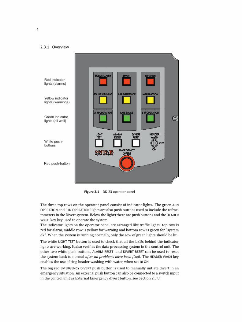
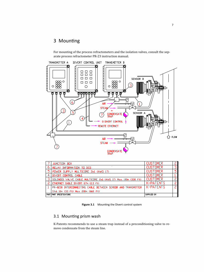
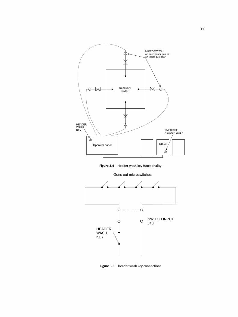
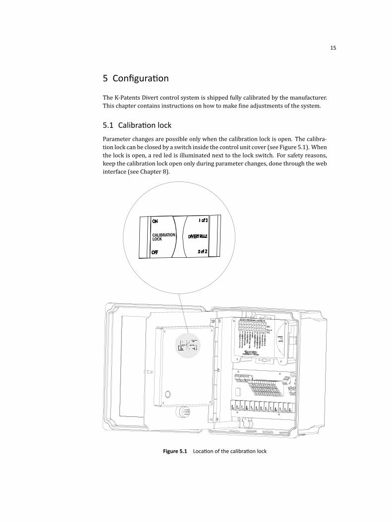
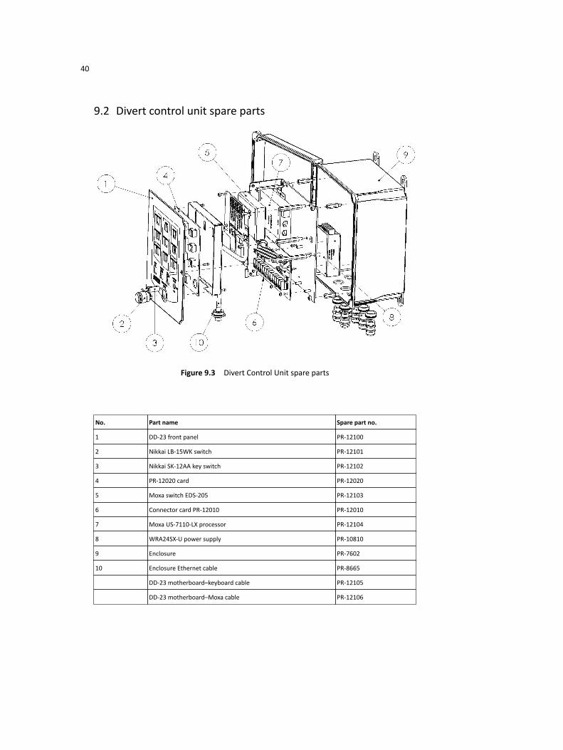