Digital Wireless Colour Camera Recordable CCTV … Digital Wireless Colour Camera Recordable CCTV...
38
Digital Wireless Colour Camera Recordable CCTV Kit CWD2 Installation and Operating Instructions Lines open Monday to Friday 9.00am to 5.00pm. Calls charged at local rates. These instructions should be retained in a safe place for future reference.
Transcript of Digital Wireless Colour Camera Recordable CCTV … Digital Wireless Colour Camera Recordable CCTV...
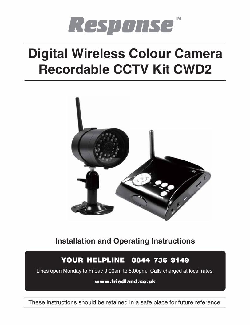
Digital Wireless Colour Camera Recordable CCTV Kit CWD2
Installation and Operating Instructions
������������ ������������
��������������� �!"
Lines open Monday to Friday 9.00am to 5.00pm. Calls charged at local rates.
These instructions should be retained in a safe place for future reference.
2
CONTENTS1. INTRODUCTION—32. KIT CONTENTS—63. INSTALLATION—83.1 Contents and Connections 83.2 Powering up the system 93.3 Setting the Camera Channel (Optional) 103.4 Pairing the Camera to Receiver (Optional) 103.5 Camera Installation 114. RECEIVER AND IR REMOTE PANEL INTRODUCTION—125. SYSTEM INTRODUCTION—135.1 Icon Functions 135.2 System Menu 146. System Operation —166.1 Camera Setup 166.2 Recorder Setup 196.3 Event List 216.4 System Setup 236.5 Alarm Buzzer 266.6 Pan Tilt Zoom 276.7 Memory Card Overwrite 287.PLAYBACK SOFTWARE—297.1 Sec24 Media Player Introduction 297.2 Installation 30����������� ��� ����������� ��7.4 Channel Disable / Enable Select 35���������� �������� ����������������������� ���10.Total Recording Time for Memory Cards (32GB max.)—3711.Battery used in the Remote Control—37
3
1. INTRODUCTION
������������ ������������
��������������� �!"
If you have any problems installing this CCTV system please refer to theTrouble Shooting sections on page 9 which should help solve any common problems, or call the Customer Helpline, available Monday to Friday 9.00am
to 5.00pm.
Calls are charged at local rates. Network charges for mobiles may vary depending on your network and call plan.
The Digital Wireless Colour Camera Recordable CCTV Kit is a wireless security system designed to view and capture video clips of any motion viewed by the wireless camera and store them in on a micro SD memory card. The wireless camera supplied is colour, ������ � ������������������ ���������������� ������ �������������� ������� ������!�����
Please read before you start:
Always use discretion when installing CCTV survillance equipment especially when there is perceived policy. Enquire regarding local regulations applicable to the lawful installation of video recording/surveillance. Third party consent may be required.
WIRELESS DEVICES OPERATING RANGE:
Ensure the signal reception viewed from the wireless camera is the best possible reception (i.e. no interference lines viewed on the TV) between the camera and receiver. If necessary reduce the distance between the camera and receiver to improve overall system performance.The Wireless Colour Camera Recordable CCTV Kit operating on a secure digital 2.4GHz frequency can greatly reduce interference from products such as wireless routers, cordless phones, microwave ovens, concrete walls, large scale metal objects, and furniture.
4
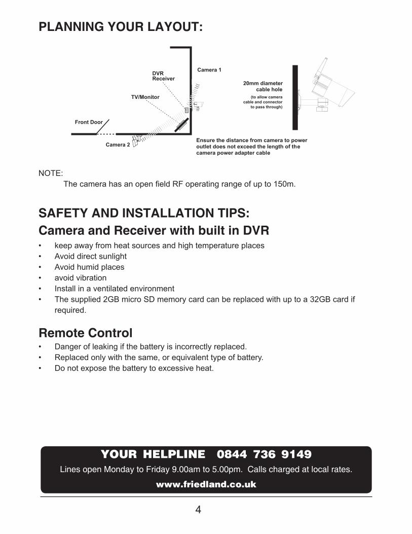
Camera 2
Camera 1
Front Door
cable hole(to allow camera
cable and connectorto pass through)
Receiver
TV/Monitor
Ensure the distance from camera to poweroutlet does not exceed the length of thecamera power adapter cable
PLANNING YOUR LAYOUT:
SAFETY AND INSTALLATION TIPS:Camera and Receiver with built in DVR
Remote Control
"� keep away from heat sources and high temperature places"� Avoid direct sunlight"� Avoid humid places"� avoid vibration "� Install in a ventilated environment"� The supplied 2GB micro SD memory card can be replaced with up to a 32GB card if
required.
������������ ������������
��������������� �!"
Lines open Monday to Friday 9.00am to 5.00pm. Calls charged at local rates.
NOTE:�#������� �������������������$%���� ������ ��������������'*+��
DVR
"� Danger of leaking if the battery is incorrectly replaced."� Replaced only with the same, or equivalent type of battery."� Do not expose the battery to excessive heat.
20mm diameter
5
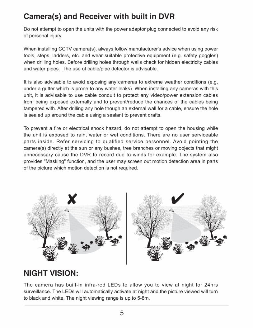
Camera(s) and Receiver with built in DVR
NIGHT VISION:
Do not attempt to open the units with the power adaptor plug connected to avoid any risk of personal injury.
When installing CCTV camera(s), always follow manufacturer's advice when using power tools, steps, ladders, etc. and wear suitable protective equipment (e.g. safety goggles)when drilling holes. Before drilling holes through walls check for hidden electricity cables and water pipes. The use of cable/pipe detector is advisable.
It is also advisable to avoid exposing any cameras to extreme weather conditions (e.g, under a gutter which is prone to any water leaks). When installing any cameras with this unit, it is advisable to use cable conduit to protect any video/power extension cables from being exposed externally and to prevent/reduce the chances of the cables being tampered with. After drilling any hole though an external wall for a cable, ensure the hole is sealed up around the cable using a sealant to prevent drafts.
#��� �<������� ��� ������ �������������=� �!���������������� ��������������������������the unit is exposed to rain, water or wet conditions. There are no user serviceable parts inside. Refer servicing to qualified service personnel. Avoid pointing the camera(s) directly at the sun or any bushes, tree branches or moving objects that might unnecessary cause the DVR to record due to winds for example. The system also provides "Masking" function, and the user may screen out motion detection area in parts of the picture which motion detection is not required.
The camera has built-in infra-red LEDs to allow you to view at night for 24hrs surveillance. The LEDs will automatically activate at night and the picture viewed will turn to black and white. The night viewing range is up to 5-8m.
6
����������
������������
��������������� �!"
Trouble Shooting page 9 or call the Customer Helpline available Monday to Friday 9.00 am to 5.00pm.
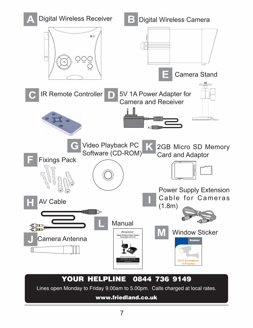
2. KIT CONTENTS
A 1 x Digital Wireless Receiver
1 x Digital Wireless CameraB'�?�@$�$������Q��� ���� ��������[�Q$\+\*����� �������C2 x 5V/1A Power Adapter for Camera and ReceiverD1 x Camera StandE1 x Fixings PackF1 x Video Playback PC Software (CD-ROM)G1 x AV Cable for TV outputH
I
J
K
LM
1 x Power Supply Adaptor Extension Cable for Camera (1.8m)
1 x Camera Antenna
1 x 2 GB Micro SD Memory Card and adaptor
1 x Manual
1 x Window Sticker
If any parts are missing contact your helpline 0844 7369149
Tools Required:Memory card reader for a PC if using playback software (only if your PC has no built in memory card reader) Safety Glasses Hammer Bradawl Electric drill No. 2 Philips screwdriver 5mm masonry drill bit 20mm masonry drill bit
7
A B Digital Wireless Camera
C DIR Remote Controller 5V 1A Power Adapter for Camera and Receiver
E
I
Camera Stand
Power Supply Extension Cab le f o r Cameras (1.8m)
Fixings Pack
2GB Micro SD Memory Card and Adaptor
Video Playback PCSoftware (CD-ROM)
FKG
H AV Cable
JL
MCamera Antenna
ManualWindow Sticker
LINKPWR.
Digital Wireless Colour Camera Recordable CCTV Kit
Installation and Operating Instructions
������������ ������������
��������������� �!"
Lines open Monday to Friday 9.00am to 5.00pm. Calls charged at local rates.
These instructions should be retained in a safe place for future reference.
������������ ������������
��������������� �!"
Lines open Monday to Friday 9.00am to 5.00pm. Calls charged at local rates.
Digital Wireless Receiver
8
3. INSTALLATION
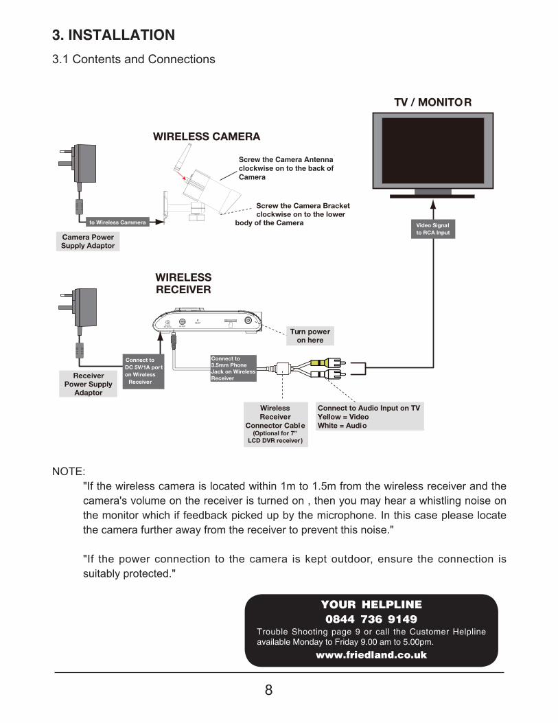
3.1 Contents and Connections
NOTE:"If the wireless camera is located within 1m to 1.5m from the wireless receiver and the camera's volume on the receiver is turned on , then you may hear a whistling noise on the monitor which if feedback picked up by the microphone. In this case please locate the camera further away from the receiver to prevent this noise."
"If the power connection to the camera is kept outdoor, ensure the connection is suitably protected."
RESET
AV OUTDC 5V/1A
TV / MONITOR
ReceiverPower Supply
Adaptor
WIRELESS CAMERA
Camera PowerSupply Adaptor
WIRELESSRECEIVER
Screw the Camera Bracketclockwise on to the lower
body of the Camera
Turn poweron here
Video Signalto RCA Input
Connect toDC 5V/1A porton Wireless
Receiver
to Wireless Cammera
Connect to3.5mm PhoneJack on WirelessReceiver
WirelessReceiver
Connector Cable(Optional for 7”
LCD DVR receiver )
Connect to Audio Input on TVYellow = Video White = Audio
����������
������������
��������������� �!"
Trouble Shooting page 9 or call the Customer Helpline available Monday to Friday 9.00 am to 5.00pm.
Screw the Camera Antennaclockwise on to the back ofCamera
9
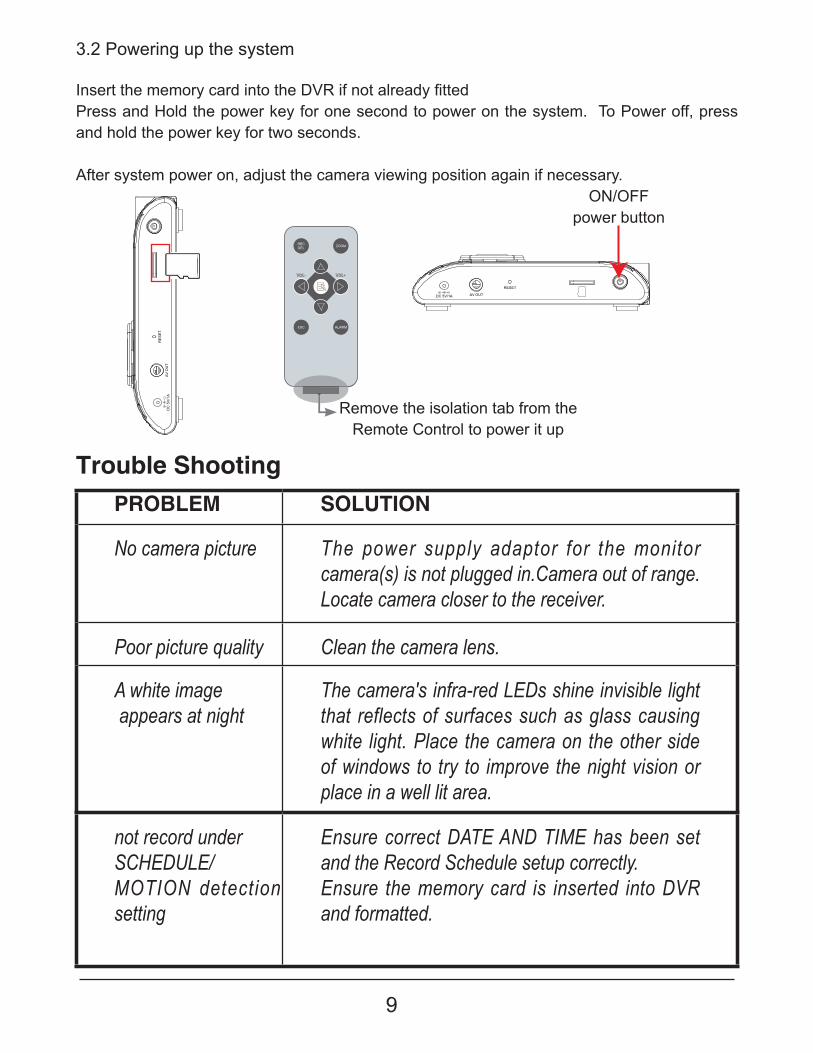
3.2 Powering up the system
Trouble Shooting
@��� ���������� ��� �����������][$���������� ���������Press and Hold the power key for one second to power on the system. To Power off, press and hold the power key for two seconds.
After system power on, adjust the camera viewing position again if necessary.
PROBLEM SOLUTION
No camera picture The power supply adaptor for the monitor camera(s) is not plugged in.Camera out of range. Locate camera closer to the receiver.
Poor picture quality Clean the camera lens.
A white image appears at night
The camera's infra-red LEDs shine invisible light that reflects of surfaces such as glass causing white light. Place the camera on the other side of windows to try to improve the night vision or place in a well lit area.
not record under SCHEDULE/MOTION detection setting
Ensure correct DATE AND TIME has been set and the Record Schedule setup correctly.Ensure the memory card is inserted into DVR and formatted.
RESET
AV OUTDC 5V/1A
RE
SE
T
AV
OU
TD
C 5
V/1
A
ON/OFFpower button
Remove the isolation tab from the Remote Control to power it up
10
3.3 Setting the Camera Channel (Optional)
3.4 Pairing the Camera to Receiver (Optional)
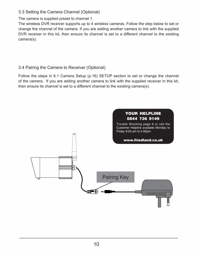
The camera is supplied preset to channel 1.The wireless DVR receiver supports up to 4 wireless cameras. Follow the step below to set or change the channel of the camera. If you are adding another camera to link with the supplied DVR receiver in this kit, then ensure its channel is set to a different channel to the existing camera(s).
Follow the steps in 6.1 Camera Setup (p.16) SETUP section to set or change the channel of the camera. If you are adding another camera to link with the supplied receiver in this kit, then ensure its channel is set to a different channel to the existing camera(s).
Pairing Key
����������
������������
��������������� �!"
Trouble Shooting page 9 or call the Customer Helpline available Monday to Friday 9.00 am to 5.00pm.
11
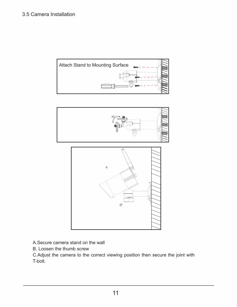
3.5 Camera Installation
Attach Stand to Mounting Surface
A.Secure camera stand on the wallB. Loosen the thumb screwC.Adjust the camera to the correct viewing position then secure the joint with T-bolt.
C
B
12
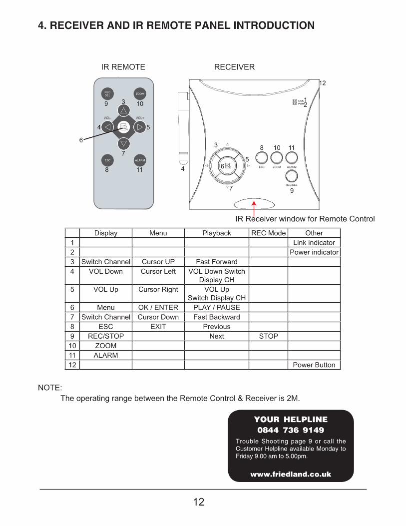
RECEIVER
IR Receiver window for Remote Control
IR REMOTE
4. RECEIVER AND IR REMOTE PANEL INTRODUCTION
LINKPWR.
1
12
11108
5
3
4 6
7 9
2
Display Menu Playback REC Mode Other1 Link indicator2 Power indicator3 Switch Channel Cursor UP Fast Forward 4 VOL Down Cursor Left VOL Down Switch
Display CH5 VOL Up Cursor Right VOL Up
Switch Display CH6 Menu OK / ENTER PLAY / PAUSE7 Switch Channel Cursor Down Fast Backward 8 ESC EXIT Previous9 REC/STOP Next STOP10 ZOOM11 ALARM12 Power Button
3
4 5
6
7
8
9 10
11
����������
������������
��������������� �!"
Trouble Shooting page 9 or call the Customer Helpline available Monday to Friday 9.00 am to 5.00pm.
NOTE:The operating range between the Remote Control & Receiver is 2M.
13
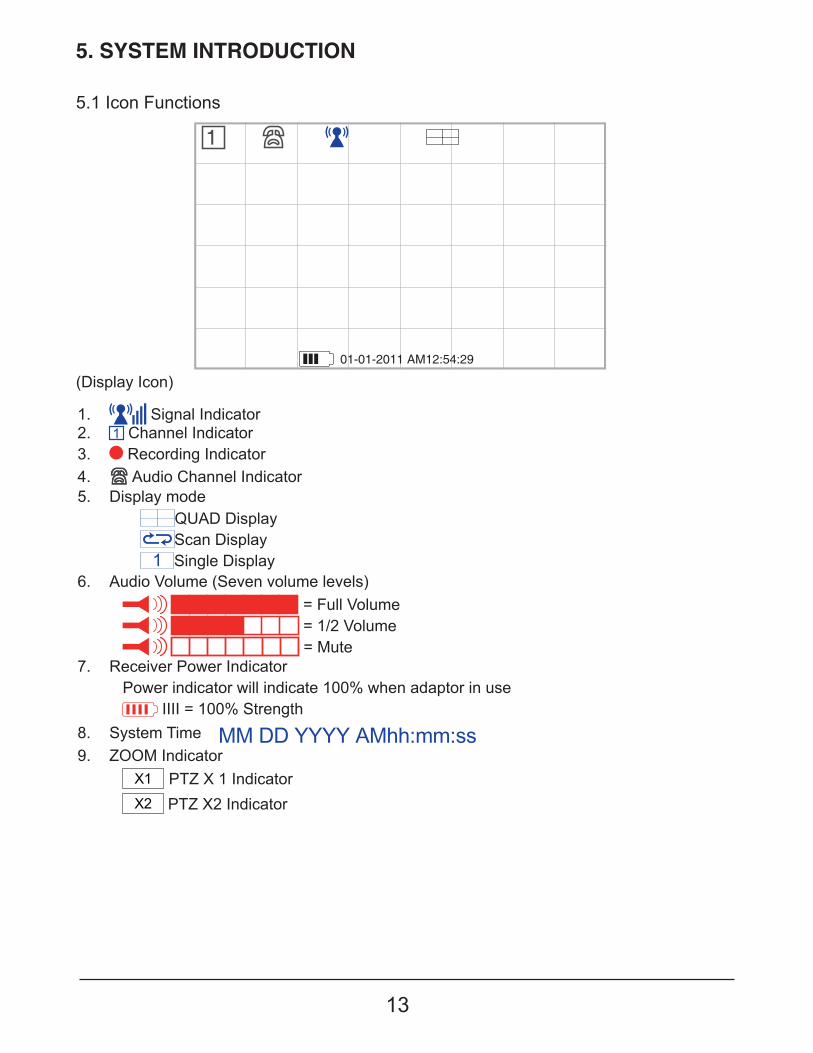
5. SYSTEM INTRODUCTION
5.1 Icon Functions
(Display Icon)
1. Signal Indicator2. Channel Indicator3. Recording Indicator4. Audio Channel Indicator5. Display mode
QUAD Display Scan Display Single Display
6. Audio Volume (Seven volume levels) = Full Volume = 1/2 Volume = Mute
7. Receiver Power IndicatorPower indicator will indicate 100% when adaptor in use
IIII = 100% Strength 8. System Time 9. ZOOM Indicator
PTZ X 1 Indicator PTZ X2 Indicator
1
01-01-2011 AM12:54:29
14
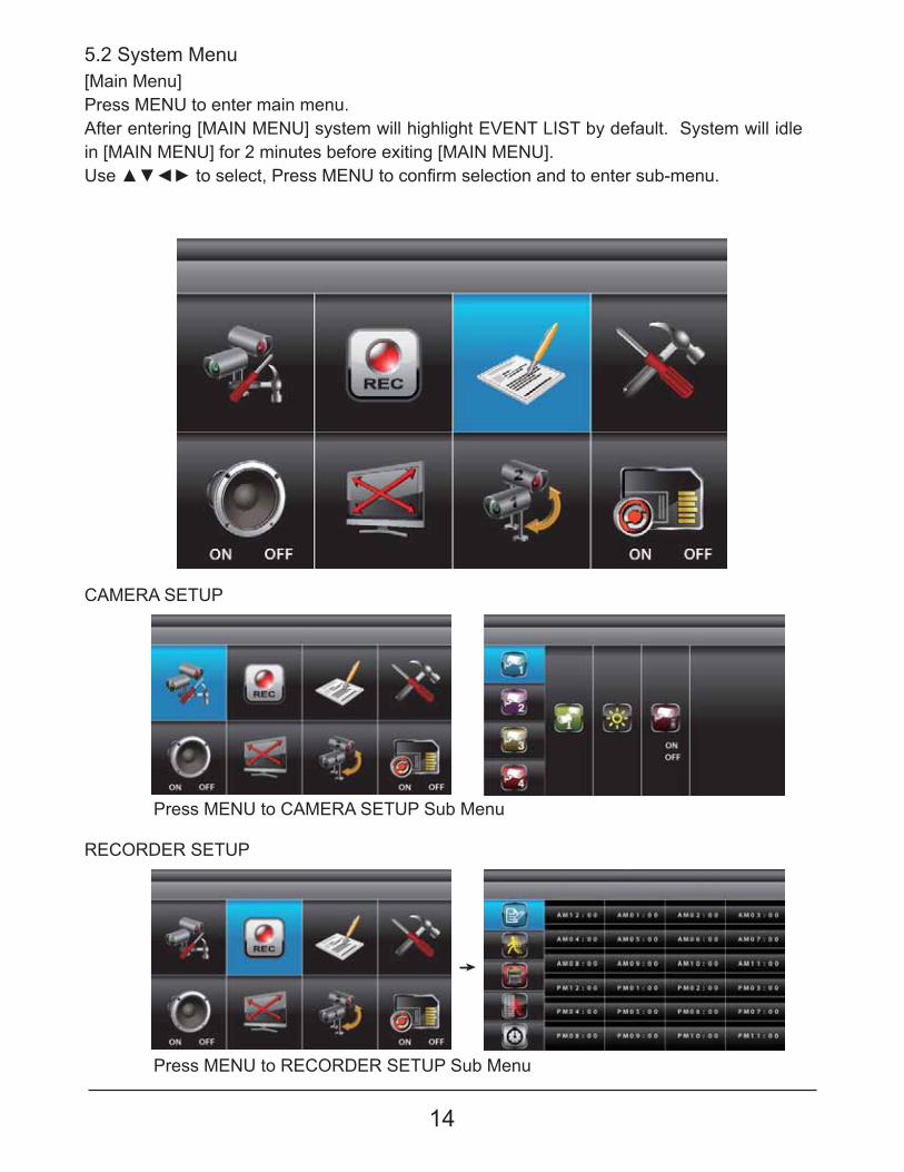
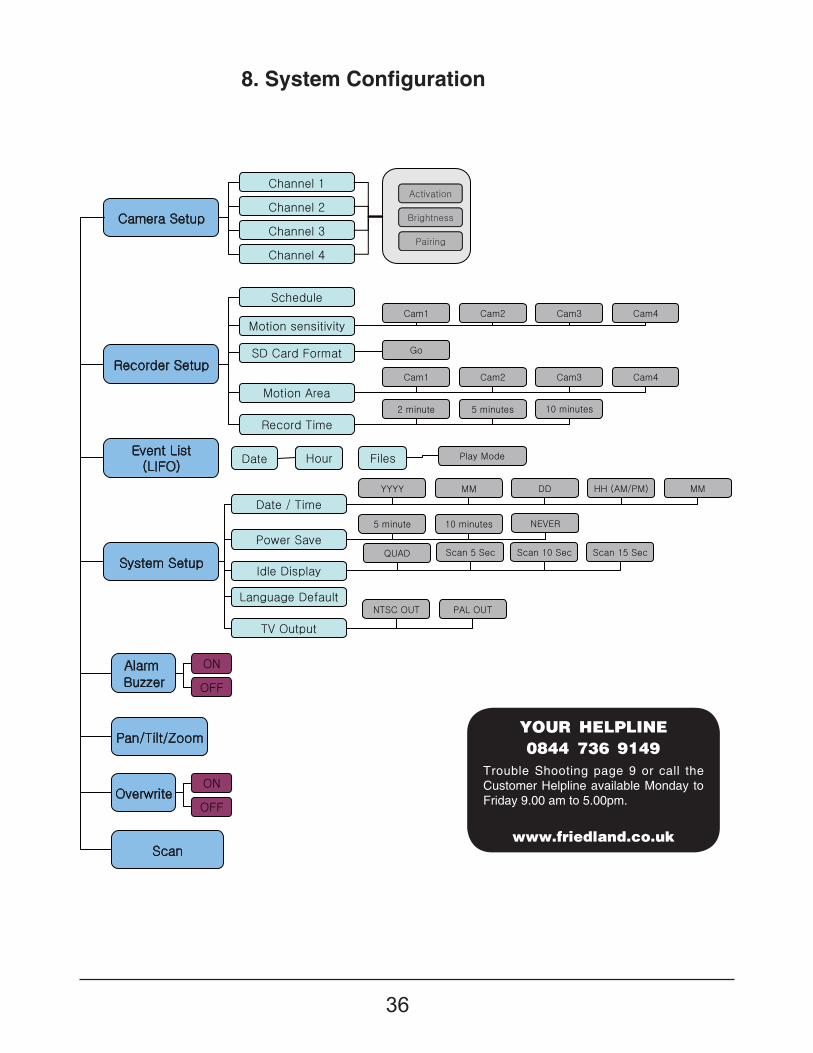
5.2 System Menu[Main Menu]Press MENU to enter main menu.After entering [MAIN MENU] system will highlight EVENT LIST by default. System will idle in [MAIN MENU] for 2 minutes before exiting [MAIN MENU]. }���~�������������!�� �������}�������� ����������������������� ���������
CAMERA SETUP
RECORDER SETUP
Press MENU to CAMERA SETUP Sub Menu
Press MENU to RECORDER SETUP Sub Menu
15
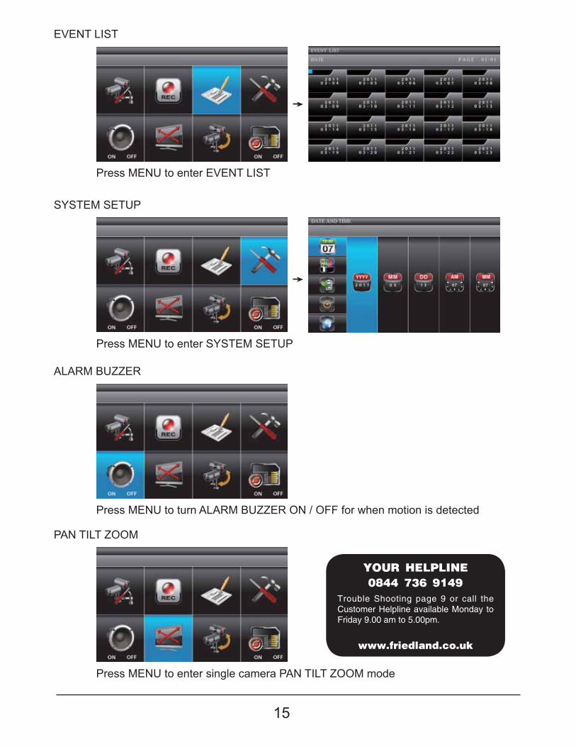
EVENT LIST
SYSTEM SETUP
ALARM BUZZER
PAN TILT ZOOM
Press MENU to enter EVENT LIST
Press MENU to enter SYSTEM SETUP
Press MENU to turn ALARM BUZZER ON / OFF for when motion is detected
Press MENU to enter single camera PAN TILT ZOOM mode
����������
������������
��������������� �!"
Trouble Shooting page 9 or call the Customer Helpline available Monday to Friday 9.00 am to 5.00pm.
16
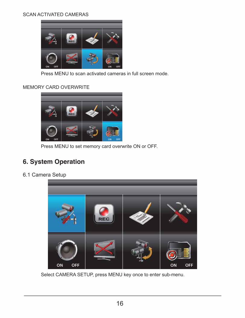
SCAN ACTIVATED CAMERAS
MEMORY CARD OVERWRITE
Press MENU to scan activated cameras in full screen mode.
Press MENU to set memory card overwrite ON or OFF.
6. System Operation
6.1 Camera Setup
Select CAMERA SETUP, press MENU key once to enter sub-menu.

17
Camera Pairing
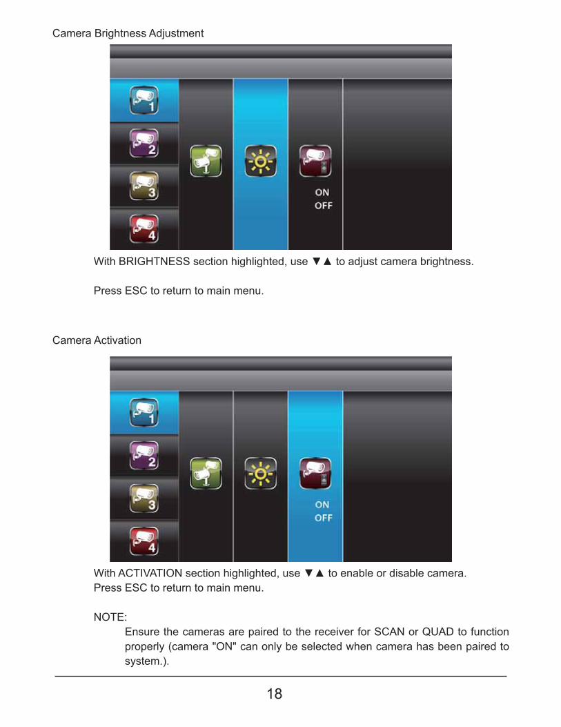
With PAIRING section highlighted, press MENU key once to begin camera pairing (pair LED on camera will blink once ). Then press and release the pairing key on the camera as shown in page 10. The link LED will stay on after camera is linked.��������������� ����� ����� ����������������������������@$�]����������������� ����
System will indicate pairing process failed with "PAIRING FAIL" displaying on screen.
Press ESC to return to main menu.
}���~������������������ �������������'�����}�����������������@$@������$@��#�������Q���$������%%�
18
������$@��#������������������������!������~��������������� �� ���������
Press ESC to return to main menu.
������Q#@[�#@����������������������!������~����������� ������������ ��Press ESC to return to main menu.
NOTE:Ensure the cameras are paired to the receiver for SCAN or QUAD to function properly (camera "ON" can only be selected when camera has been paired to system.).
Camera Brightness Adjustment
Camera Activation
19
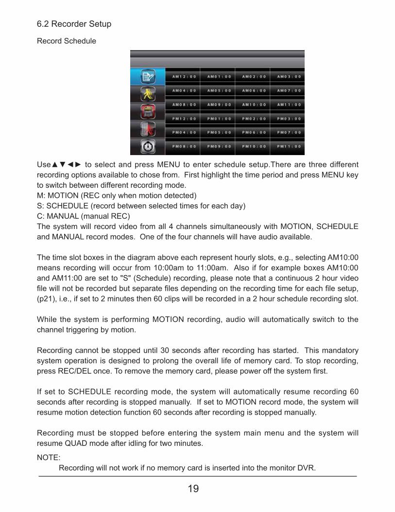
Record Schedule
}��~������������������� �������}�������� ����������������#�� ��� �� �� �������� ����recording options available to chose from. First highlight the time period and press MENU key to switch between different recording mode.M: MOTION (REC only when motion detected)S: SCHEDULE (record between selected times for each day)C: MANUAL (manual REC)The system will record video from all 4 channels simultaneously with MOTION, SCHEDULE and MANUAL record modes. One of the four channels will have audio available.
The time slot boxes in the diagram above each represent hourly slots, e.g., selecting AM10:00 means recording will occur from 10:00am to 11:00am. Also if for example boxes AM10:00 and AM11:00 are set to "S" (Schedule) recording, please note that a continuous 2 hour video ��������������� ��� ����������� �������������������������� ��� ������������ ���������������!�(p21), i.e., if set to 2 minutes then 60 clips will be recorded in a 2 hour schedule recording slot.
While the system is performing MOTION recording, audio will automatically switch to the channel triggering by motion.
Recording cannot be stopped until 30 seconds after recording has started. This mandatory system operation is designed to prolong the overall life of memory card. To stop recording, � ����$�Q�]���������#�� ���<���������� ��� �!������������ ���������������� �����
If set to SCHEDULE recording mode, the system will automatically resume recording 60 seconds after recording is stopped manually. If set to MOTION record mode, the system will resume motion detection function 60 seconds after recording is stopped manually.
Recording must be stopped before entering the system main menu and the system will resume QUAD mode after idling for two minutes.
6.2 Recorder Setup
NOTE:Recording will not work if no memory card is inserted into the monitor DVR.

20
Setup Masking Area
NOTE:@������������ ��� ��������������������������� �������� ����� ����� ������
Select RECORDER SETUP, press MENU to enter. }���~����������������@����$����������}����������������������� ���� ������!�� �������}�������� }������~��������������������� ����� ������������������������������ ����}������}�key to mask/unmask grid(s). Movements taking place inside masked area will be ���� ���}�����~������������������ �� ����� �������� �� ������Q������<�������?��
Motion Detection Sensitivity
Format Memory Card
Select RECORDER SETUP, press MENU to enter. }���~��������������#@���]�#�Q#@�������@#@[@#���������}����������������������� ���� ������}���~�������������������<�����<�����%%����['����[\����[����[�����������������<��Press ESC to save and exit
Select RECORDER SETUP, press MENU to enter}���~������������%�$��#��#�$���!�� �������}�������� � �������}�������������� ������������� ������������ ��� �Press ESC to exit
21
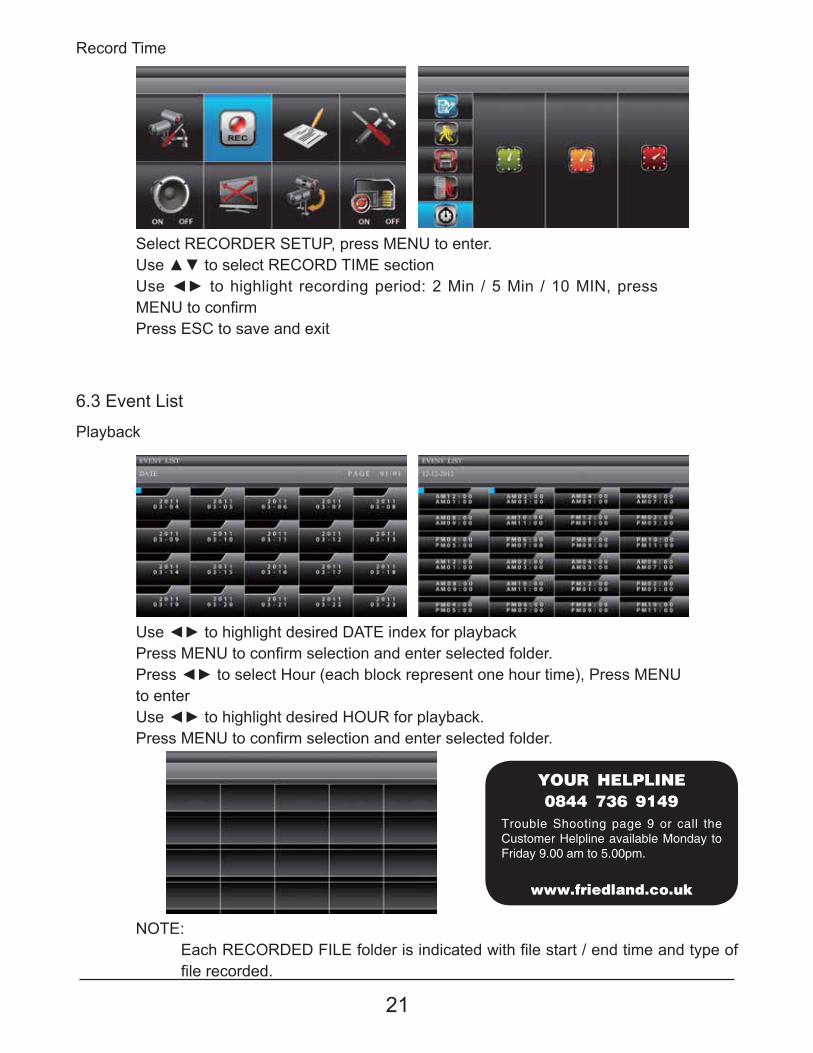
Record Time
Playback
Select RECORDER SETUP, press MENU to enter. }���~������������$�Q�$]�#@����������}������������������� ��� ������� �����\����� ��*����� ��'+��@�!�� �������}�������� �Press ESC to save and exit
}����������������������� ���]�#������?��� �������� �������}�������� �������������������� ��������������� �� �������������������� ������������ �� ������������� ������!�� �������}�to enter}����������������������� �����}$��� ��������� �������}�������� �������������������� ��������������� �
NOTE:�����$�Q�$]�]�%@�������� �������������������������� ���������������������������� ��� �����
6.3 Event List
����������
������������
��������������� �!"
Trouble Shooting page 9 or call the Customer Helpline available Monday to Friday 9.00 am to 5.00pm.
22
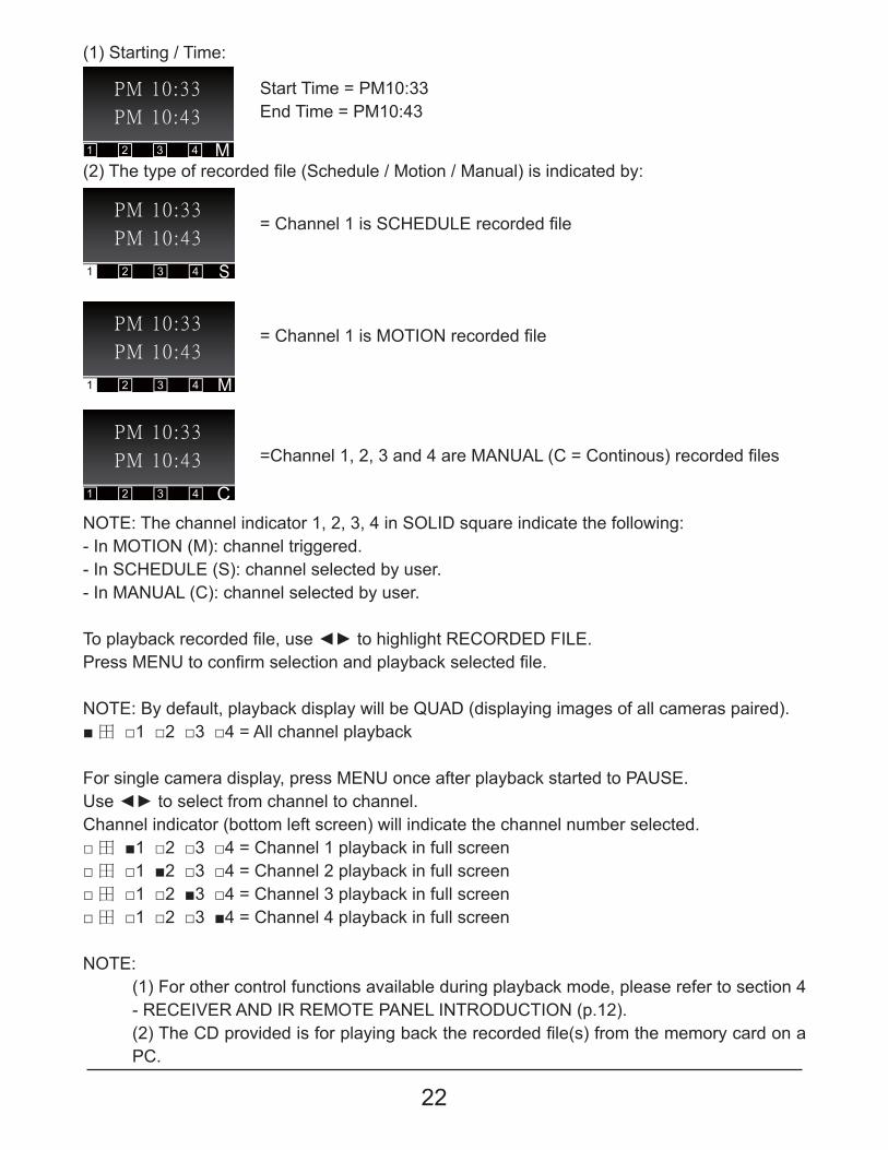
NOTE: The channel indicator 1, 2, 3, 4 in SOLID square indicate the following:- In MOTION (M): channel triggered.- In SCHEDULE (S): channel selected by user.- In MANUAL (C): channel selected by user.
#��������� ��� �������!���������������������$�Q�$]�]�%@���� �������}�������� ������������������������������������
NOTE: By default, playback display will be QUAD (displaying images of all cameras paired). � ���'���\�����������������������������
For single camera display, press MENU once after playback started to PAUSE.}����������������� �����������������������Channel indicator (bottom left screen) will indicate the channel number selected. � ���'���\�����������Q�������'������������������ ���� ���'���\�����������Q�������\������������������ ���� ���'���\�����������Q�������������������������� ���� ���'���\�����������Q�������������������������� ���
NOTE: (1) For other control functions available during playback mode, please refer to section 4 - RECEIVER AND IR REMOTE PANEL INTRODUCTION (p.12).�\��#���Q]�� �<���������� ���������������� ��� ������������ ����������� ��� �������PC.
�Q�������'!�\!���������� �����}����Q���Q���������� ��� ��������
(1) Starting / Time:
�\��#���������� ��� ���������������������������������������������������
Start Time = PM10:33End Time = PM10:43
��Q�������'�����Q��]}��� ��� �������
��Q�������'������#@��� ��� �������
23
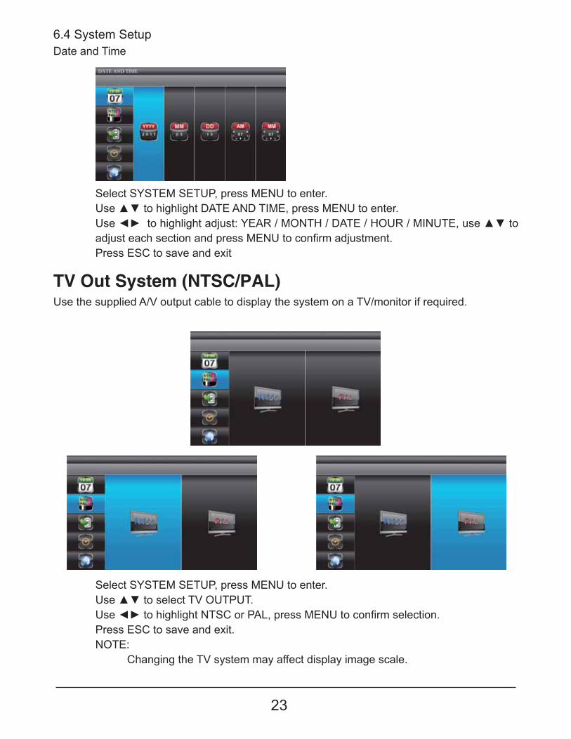
Select SYSTEM SETUP, press MENU to enter. }���~������������#[��}#�}#�}��������������������#�Q�� ����!�� �������}�������� ������������Press ESC to save and exit.NOTE:
Changing the TV system may affect display image scale.
Use the supplied A/V output cable to display the system on a TV/monitor if required.
TV Out System (NTSC/PAL)
Select SYSTEM SETUP, press MENU to enter. }���~���������������]�#����]�#@��!�� �������}�������� �}�������������������������������$������#����]�#������}$����@�}#�!�����~������������������������������ �������}�������� �������������Press ESC to save and exit
Date and Time6.4 System Setup
24
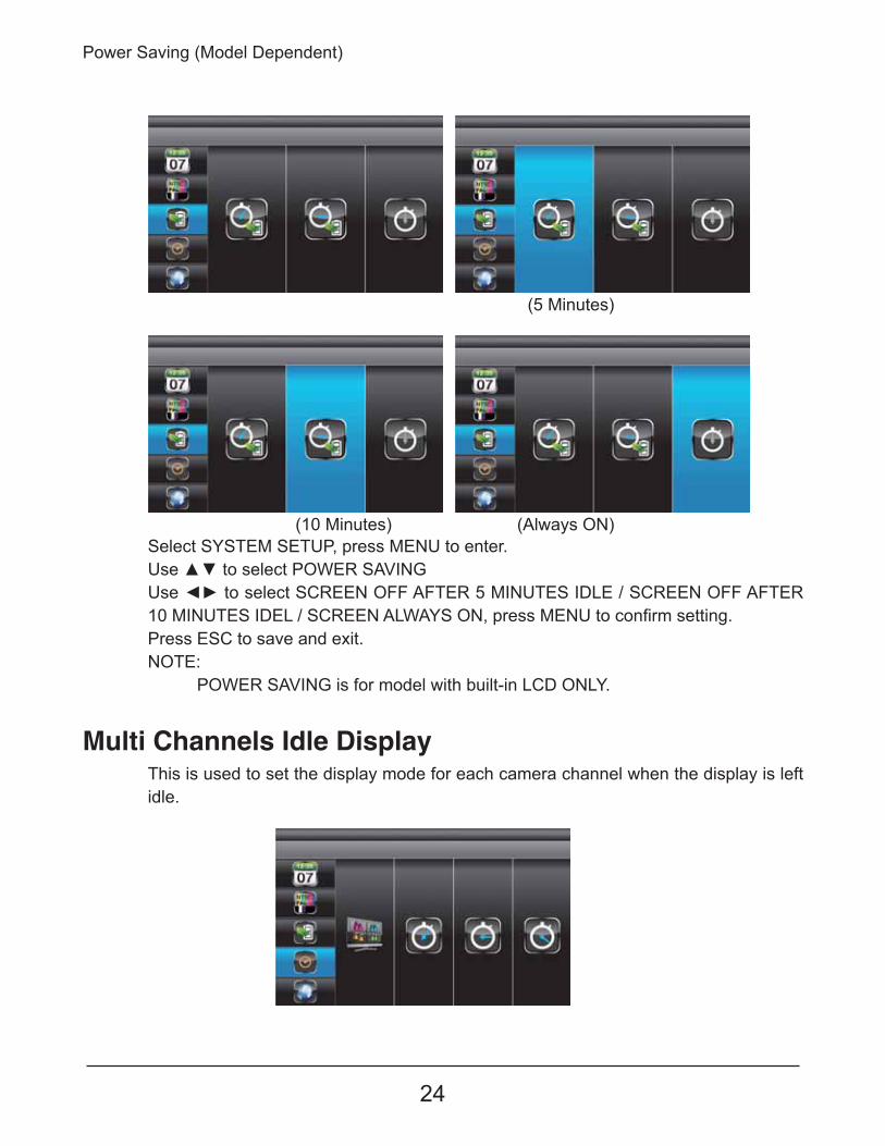
Select SYSTEM SETUP, press MENU to enter. }���~����������������$���[@��}�����������������Q$�����%%��%#�$�*��@�}#���@]������Q$�����%%��%#�$�'+��@�}#���@]������Q$�������������!�� �������}�������� ����������Press ESC to save and exit.NOTE:
POWER SAVING is for model with built-in LCD ONLY.
(10 Minutes) (Always ON)
(5 Minutes)
Power Saving (Model Dependent)
Multi Channels Idle DisplayThis is used to set the display mode for each camera channel when the display is left idle.
25
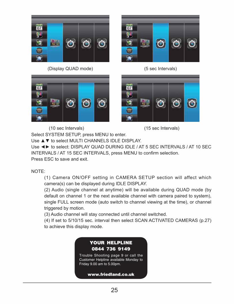
(5 sec Intervals)
(15 sec Intervals)
(Display QUAD mode)
(10 sec Intervals)Select SYSTEM SETUP, press MENU to enter. }���~�������������}�#@�Q��������@]���]@������}�����������������]@�������}�]�]}$@���@]������#�*���Q�@�#�$[�������#�'+���Q�@�#�$[�������#�'*���Q�@�#�$[���!�� �������}�������� ������������Press ESC to save and exit.
NOTE:(1) Camera ON/OFF setting in CAMERA SETUP section will affect which camera(s) can be displayed during IDLE DISPLAY.(2) Audio (single channel at anytime) will be available during QUAD mode (by default on channel 1 or the next available channel with camera paired to system), single FULL screen mode (auto switch to channel viewing at the time), or channel triggered by motion.(3) Audio channel will stay connected until channel switched.(4) If set to 5/10/15 sec. interval then select SCAN ACTIVATED CAMERAS (p.27) to achieve this display mode.
����������
������������
��������������� �!"
Trouble Shooting page 9 or call the Customer Helpline available Monday to Friday 9.00 am to 5.00pm.
26
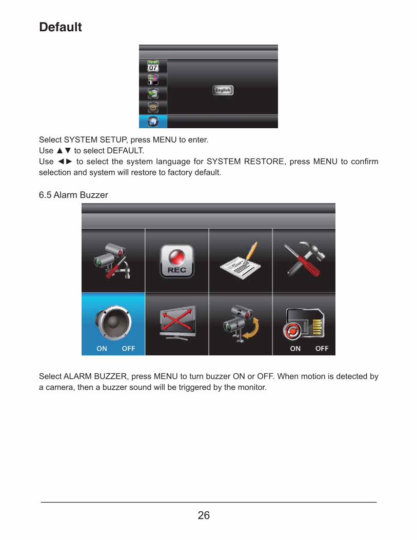
Default
6.5 Alarm Buzzer
Select SYSTEM SETUP, press MENU to enter. }���~������������]�%�}�#�}���������������� ���������� ��������� �� ����#���$��#�$�!�� �������}��������� ��selection and system will restore to factory default.
Select ALARM BUZZER, press MENU to turn buzzer ON or OFF. When motion is detected by a camera, then a buzzer sound will be triggered by the monitor.
27
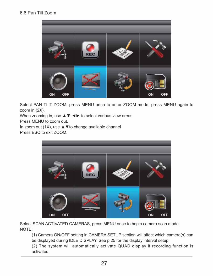
6.6 Pan Tilt Zoom
Select SCAN ACTIVATED CAMERAS, press MENU once to begin camera scan mode.NOTE:
(1) Camera ON/OFF setting in CAMERA SETUP section will affect which camera(s) can be displayed during IDLE DISPLAY. See p.25 for the display interval setup.(2) The system will automatically activate QUAD display if recording function is activated.
Select PAN TILT ZOOM, press MENU once to enter ZOOM mode, press MENU again to zoom in (2X). �����=���������!�����~���������������<� �����<����� ����Press MENU to zoom out.@��=���������'��!�����~������������<��������������Press ESC to exit ZOOM.
28
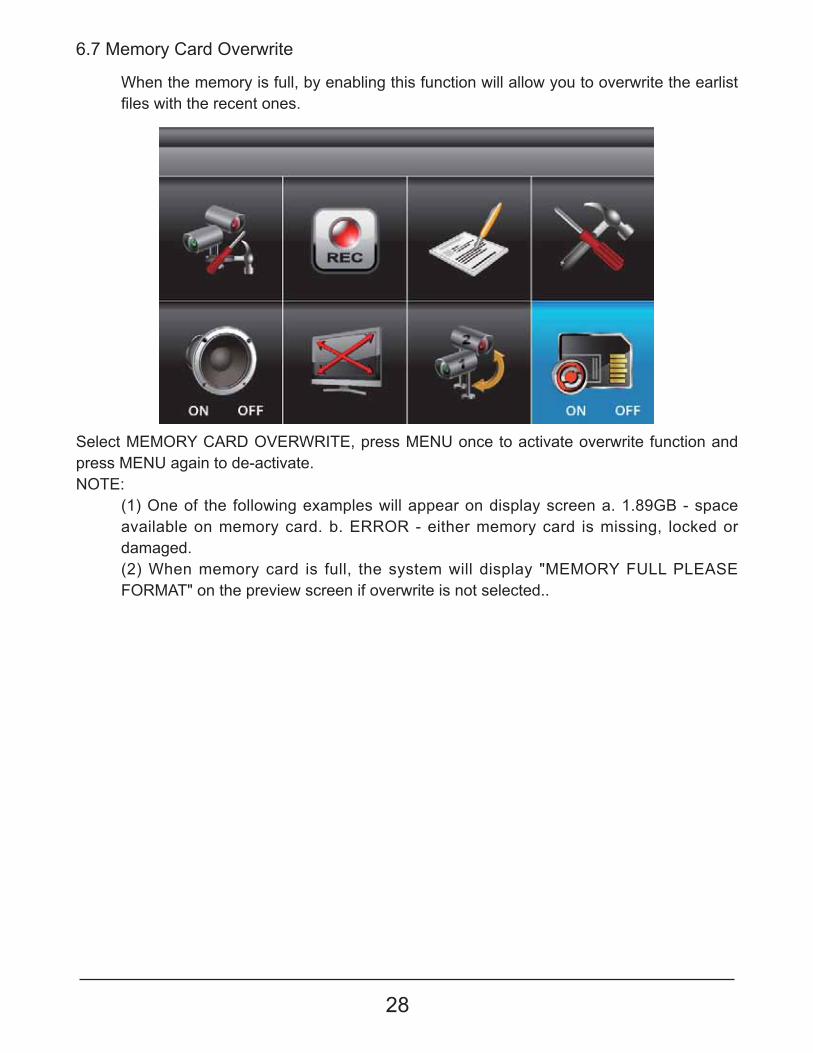
6.7 Memory Card Overwrite
Select MEMORY CARD OVERWRITE, press MENU once to activate overwrite function and press MENU again to de-activate.NOTE:
(1) One of the following examples will appear on display screen a. 1.89GB - space available on memory card. b. ERROR - either memory card is missing, locked or damaged.(2) When memory card is full, the system will display "MEMORY FULL PLEASE FORMAT" on the preview screen if overwrite is not selected..
When the memory is full, by enabling this function will allow you to overwrite the earlist �������������� �����������
29
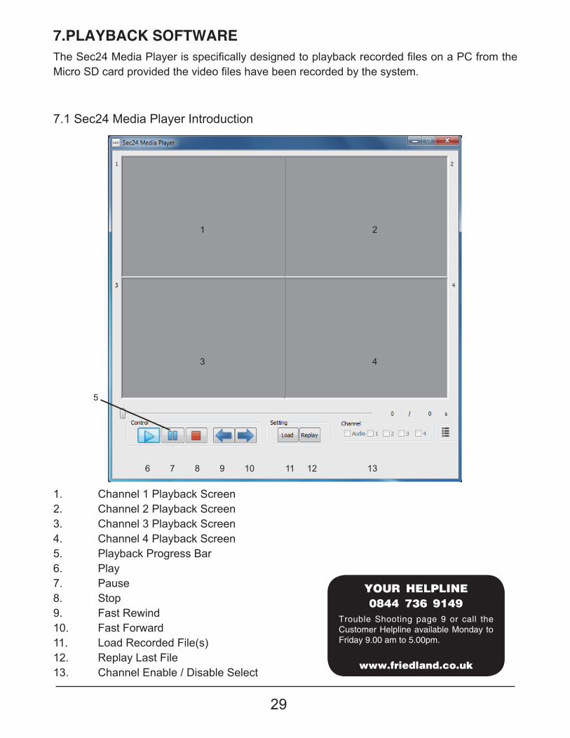
7.PLAYBACK SOFTWARE#������\������������ ���������������������������������� ��� ���������������Q�� ���������� ���]��� ��� �<���������<������������<������ ��� ���������������
1. Channel 1 Playback Screen2. Channel 2 Playback Screen3. Channel 3 Playback Screen4. Channel 4 Playback Screen5. Playback Progress Bar6. Play7. Pause8. Stop9. Fast Rewind10. Fast Forward11. Load Recorded File(s)12. Replay Last File13. Channel Enable / Disable Select
7.1 Sec24 Media Player Introduction
1
3
2
4
5
6 7 8 9 10 11 12 13
����������
������������
��������������� �!"
Trouble Shooting page 9 or call the Customer Helpline available Monday to Friday 9.00 am to 5.00pm.
30
Insert the CD into the CD-ROM of the PC. Click on MY COMPUTER, double click on the drive where the CD-ROM is assigned by the PC (for example: E;\). In this drive you will find the following icon. Please read the following steps to complete installation.
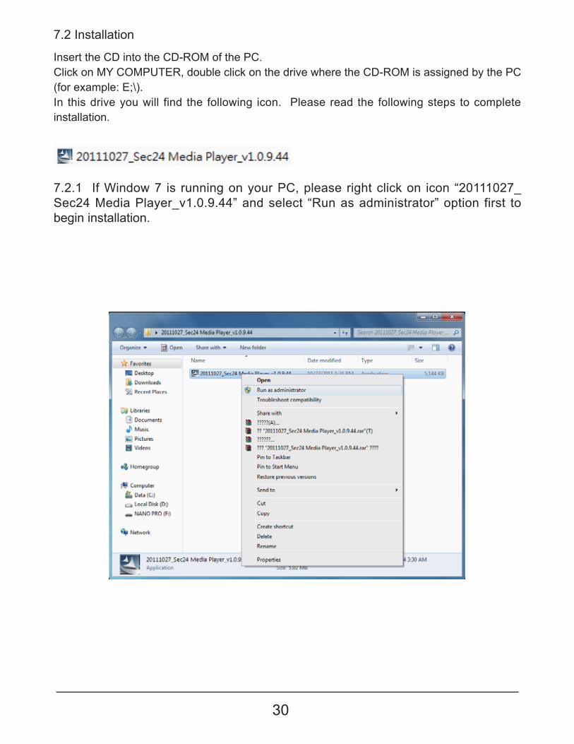
7.2.1 If Window 7 is running on your PC, please right click on icon “20111027_Sec24 Media Player_v1.0.9.44” and select “Run as administrator” option first to begin installation.
7.2 Installation

31
7.2.2 The following error message will appear if you did not select “Run as �������� ��� ��������� ������ ����� ����������������������
7.2.3 Double click the icon to start installation process.
32
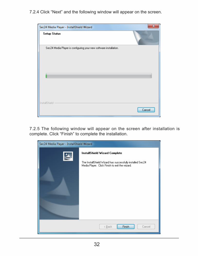
7.2.4 Click “Next” and the following window will appear on the screen.
7.2.5 The following window will appear on the screen after installation is complete. Click “Finish” to complete the installation.
33
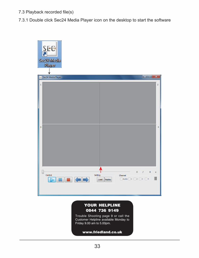
7.3.1 Double click Sec24 Media Player icon on the desktop to start the software
����������� ��� ����������
����������
������������
��������������� �!"
Trouble Shooting page 9 or call the Customer Helpline available Monday to Friday 9.00 am to 5.00pm.
34
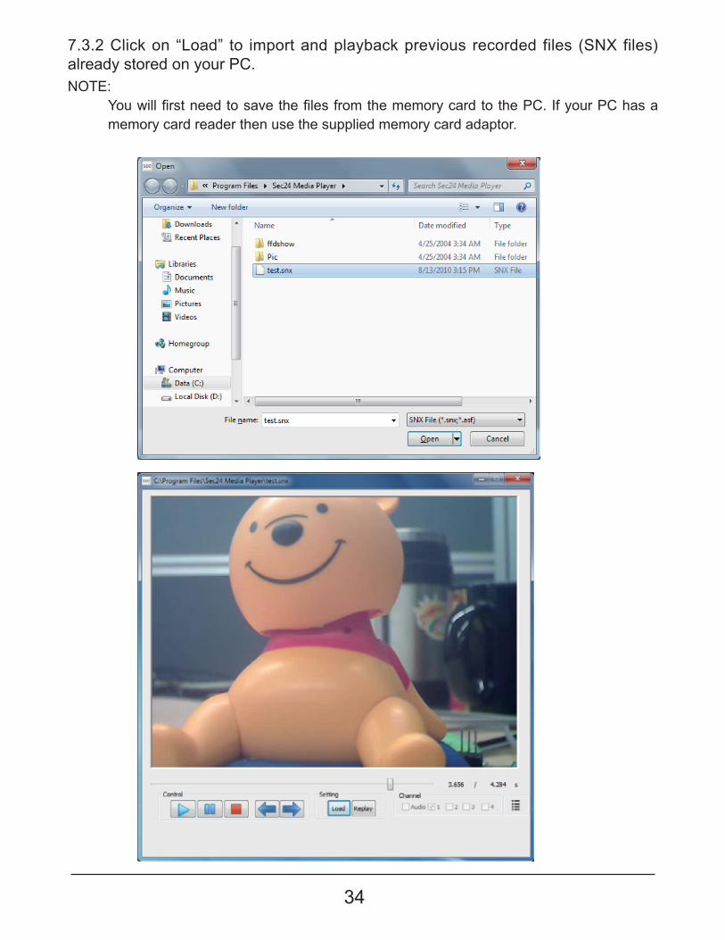
7.3.2 Click on “Load” to import and playback previous recorded files (SNX files) already stored on your PC.NOTE:
���������� �������������<������������ ����������� ��� ����������Q��@���� ��Q�������memory card reader then use the supplied memory card adaptor.
35
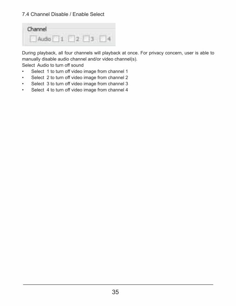
During playback, all four channels will playback at once. For privacy concern, user is able to manually disable audio channel and/or video channel(s). Select Audio to turn off sound"� Select 1 to turn off video image from channel 1"� Select 2 to turn off video image from channel 2"� Select 3 to turn off video image from channel 3"� Select 4 to turn off video image from channel 4
7.4 Channel Disable / Enable Select
36
���������� ��������
����������
������������
��������������� �!"
Trouble Shooting page 9 or call the Customer Helpline available Monday to Friday 9.00 am to 5.00pm.
37
��������������������
10.Total Recording Time for Memory Cards (32GB max.)
11.Battery used in the Remote Control
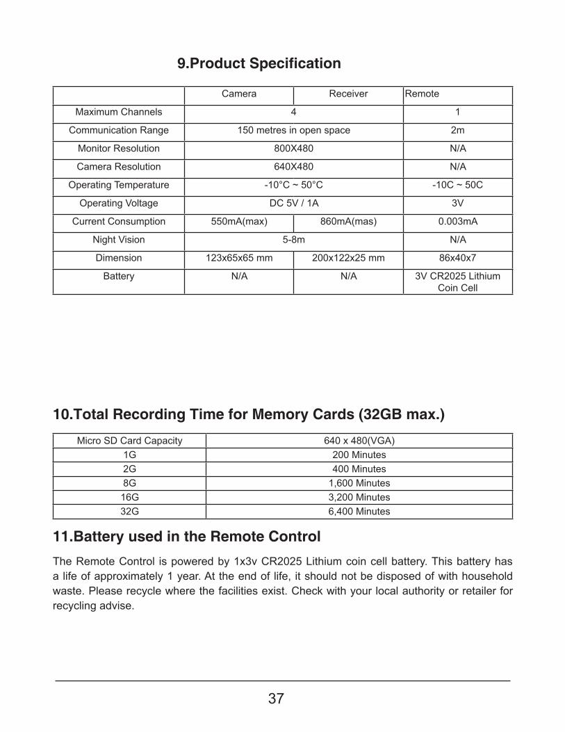
Camera Receiver Remote
Maximum Channels 4 1
Communication Range 150 metres in open space 2m
Monitor Resolution 800X480 N/A
Camera Resolution 640X480 N/A
Operating Temperature -10°C ~ 50°C -10C ~ 50C
Operating Voltage DC 5V / 1A 3V
Current Consumption 550mA(max) 860mA(mas) 0.003mA
Night Vision 5-8m N/A
Dimension 123x65x65 mm 200x122x25 mm 86x40x7
Battery N/A N/A 3V CR2025 Lithium Coin Cell
Micro SD Card Capacity 640 x 480(VGA)1G 200 Minutes2G 400 Minutes8G 1,600 Minutes16G 3,200 Minutes32G 6,400 Minutes
The Remote Control is powered by 1x3v CR2025 Lithium coin cell battery. This battery has a life of approximately 1 year. At the end of life, it should not be disposed of with household waste. Please recycle where the facilities exist. Check with your local authority or retailer for recycling advise.
38
#���� ������ ����������������������������� ������ ������ ������¢���������������]� ����<���It should not be disposed of with other household or other commercial waste. At the end of its useful life the packaging and product should be disposed of via a suitable recycling centre. For information on available facilities, please contact your local authority or retailer from where the product was purchased.
Batteries and waste electrical products should not be disposed of with household waste.Please recycle where facilities exist.Check with your local authority or retailer for recycling advise.
Novar ED&S undertakes to replace or repair at its discretion goods, should they become defective within 1 year solely as a result of faulty materials and workmanship.
Understandable if the product has not been installed, operated or maintained in accordance with the instructions, has not been used appropriately or if any attempt has been made to rectify, dismantle or alter the product in any way the guarantee will be invalidated.
The guarantee states Novar ED&S entire liability. It does not extent to cover consequential loss or damage or installation costs arising from the defective product. This guarantee does not in any way affect the statutory or other rights of a consumer and applies to products installed within UK and Eire only. If an item develops a fault, the product must be returned to the point of sale with:1. Proof of purchase.2. A full description of the fault.3. All relevant batteries (disconnected).
Guarantee
Disposal and Recycling (Directive 2002/96/EC)
CUSTOMER HELPLINE0844 736 9149
Most issues can be solved over the phone in a few minutes. Please contact our Helpline Team on the above number for any installation and general advice regarding our products.Lines open 9.00am to 5.00pm, Monday to Friday. Calls are charged at service providers national rate.
Novar Electrical Devices and Systems Limited (A Honeywell company)The Arnold Centre, Paycocke Road, Basildon, Essex SS14 3EA. UK
www.friendland.co.ukNovar Electrical Devices and Systems Limited. 2011
50069283-001 Rev. B