
Digital Standard: CDMA2000 incl. 1xEV-DV · CDMA2000® incl. 1xEV-DV Digital Standard for R&S ......
174
CDMA2000® incl. 1xEV-DV Digital Standard for R&S ® Signal Generators Operating Manual Operating Manual (;ÕÂI<) 1171.5225.12 ─ 14 Test & Measurement
Transcript of Digital Standard: CDMA2000 incl. 1xEV-DV · CDMA2000® incl. 1xEV-DV Digital Standard for R&S ......

CDMA2000® incl. 1xEV-DVDigital Standard forR&S®Signal GeneratorsOperating Manual
Oper
ating
Man
ual
(;ÕÂI<)1171.5225.12 ─ 14
Test
& Me
asur
emen
t

This document describes the following software options:
● R&S®AMU-K46/-K2461402.6506.02, 1402.8109.02
● R&S®SMATE-K461404.5507.02
● R&S®SMBV-K46/-K2461415.8083.xx, 1415.8283.xx
● R&S®SMJ-K46/-K2461409.1016.02
● R&S®SMU-K46/-K2461160.9876.02, 1408.6014.02
● R&S®SMW-K2461413.4939.02
● R&S®AFQ-K2461401.6554.02
● R&S®CMW-KW8001203.1506.02
● R&S®SFU-K2462115.2289.02
© 2013 Rohde & Schwarz GmbH & Co. KGMühldorfstr. 15, 81671 München, GermanyPhone: +49 89 41 29 - 0Fax: +49 89 41 29 12 164E-mail: [email protected]: www.rohde-schwarz.comSubject to change – Data without tolerance limits is not binding.R&S® is a registered trademark of Rohde & Schwarz GmbH & Co. KG.CDMA2000® is a registered trademark of the Telecommunications Industry Association (TIA -USA).Trade names are trademarks of the owners.
The following abbreviations are used throughout this manual: R&S®AMU200A is abbreviated as R&S AMU, R&S®SMATE200A isabbreviated as R&S SMATE, R&S®SMBV100A is abbreviated as R&S SMBV, R&S®SMJ100A is abbreviated as R&S SMJ,R&S®SMU200A is abbreviated as R&S SMU, R&S®SMW200A is abbreviated as R&S SMW, R&S®WinIQSIM2TM is abbreviated asR&S WinIQSIM2

ContentsCDMA2000® incl. 1xEV-DV
3Operating Manual 1171.5225.12 ─ 14
Contents1 Preface.................................................................................................... 7
1.1 Documentation Overview............................................................................................. 7
1.2 Typographical Conventions.........................................................................................8
2 Introduction............................................................................................ 9
3 Modulation System CDMA2000.......................................................... 113.1 Modulation System CDMA2000 in the Downlink (Forward).................................... 11
3.2 Modulation System CDMA2000 in the Uplink (Reverse)......................................... 11
3.3 Data Source - Uplink and Downlink...........................................................................12
3.4 Channel Coding - Uplink and Downlink.................................................................... 12
3.5 Long-Code Scrambling Generator - Downlink......................................................... 13
3.6 Power Control Puncturing - Downlink.......................................................................14
3.7 Variable-Length Walsh Spreading - Downlink..........................................................14
3.8 PN Short-Code Scrambling - Downlink.....................................................................14
3.9 Spreading - Uplink...................................................................................................... 14
3.9.1 Variable Length Walsh Spreading.................................................................................15
3.9.2 64-ary Orthogonal Modulator........................................................................................ 15
3.10 Scrambling - Uplink.................................................................................................... 15
3.10.1 Scrambling for Radio Configuration 1 and 2 ................................................................ 15
3.10.2 Scrambling for Radio Configuration 3, 4 and 5............................................................. 17
3.11 Baseband Filtering - Uplink and Downlink............................................................... 18
3.12 I/Q Modulator - Uplink and Downlink.........................................................................18
3.13 Constellation of I/Q Signals - Downlink.................................................................... 19
3.13.1 BPSK channels............................................................................................................. 19
3.13.2 QPSK channels.............................................................................................................19
3.14 Power Control - Downlink and Uplink....................................................................... 20
4 User Interface....................................................................................... 214.1 General Settings for CDMA2000 Signals.................................................................. 22
4.2 Configure Base Station or Mobile Station................................................................ 27
4.3 Filter / Clipping / ARB Settings.................................................................................. 31
4.3.1 Filter Settings................................................................................................................ 31

ContentsCDMA2000® incl. 1xEV-DV
4Operating Manual 1171.5225.12 ─ 14
4.3.2 Clipping Settings........................................................................................................... 32
4.3.3 ARB Settings.................................................................................................................36
4.3.4 I/Q Setting..................................................................................................................... 36
4.4 Trigger/Marker/Clock Settings................................................................................... 37
4.4.1 Trigger In.......................................................................................................................38
4.4.2 Marker Mode................................................................................................................. 42
4.4.3 Marker Delay.................................................................................................................43
4.4.4 Clock Settings............................................................................................................... 43
4.4.5 Global Settings..............................................................................................................45
4.5 Predefined Settings - Downlink................................................................................. 46
4.6 Additional Mobile Station - Uplink.............................................................................49
4.7 Base Station Configuration........................................................................................50
4.7.1 Common Settings..........................................................................................................51
4.7.2 Code Domain and Channel Graphs.............................................................................. 53
4.7.3 Channel Table - BS.......................................................................................................57
4.8 More Parameters - BS Channel Table....................................................................... 63
4.8.1 General Settings........................................................................................................... 65
4.8.2 Power Control............................................................................................................... 66
4.8.3 Channel Coding............................................................................................................ 68
4.8.4 Additional Sync Channel Parameters........................................................................... 70
4.8.5 Error Insertion............................................................................................................... 72
4.9 More Parameters for F-PDCH - BS............................................................................ 73
4.9.1 General Settings for Packet Channel............................................................................74
4.9.2 Subpacket Table Settings............................................................................................. 75
4.9.3 Subpacket Graph.......................................................................................................... 78
4.10 Mobile Station Configuration (MS)............................................................................ 78
4.10.1 Common Settings - MS................................................................................................. 79
4.10.2 Power Control - MS.......................................................................................................80
4.10.3 Channel Table - MS...................................................................................................... 82
5 Remote-Control Commands............................................................... 875.1 Primary Commands.................................................................................................... 88
5.2 Filter/Clipping Settings...............................................................................................95
5.2.1 Filter Settings................................................................................................................ 95

ContentsCDMA2000® incl. 1xEV-DV
5Operating Manual 1171.5225.12 ─ 14
5.2.2 Clipping Settings......................................................................................................... 100
5.3 Trigger Settings.........................................................................................................101
5.4 Marker Settings......................................................................................................... 107
5.5 Clock Settings........................................................................................................... 111
5.6 Predefined Settings.................................................................................................. 114
5.7 Setting Base Stations............................................................................................... 119
5.8 Mobile Station Settings............................................................................................ 154
List of Commands..............................................................................168
Index....................................................................................................172

ContentsCDMA2000® incl. 1xEV-DV
6Operating Manual 1171.5225.12 ─ 14

PrefaceCDMA2000® incl. 1xEV-DV
7Operating Manual 1171.5225.12 ─ 14
1 Preface
1.1 Documentation Overview
The user documentation for the R&S Signal Generator consists of the following parts:
● Online Help system on the instrument,● "Quick Start Guide" printed manual,● Documentation CD-ROM with:
– Online help system (*.chm) as a standalone help,– Operating Manuals for base unit and options,– Service Manual,– Data sheet and specifications,– Links to useful sites on the R&S internet.
Online Help
The Online Help is embedded in the instrument's firmware. It offers quick, context-sen-sitive access to the complete information needed for operation and programming. Theonline help contains help on operating the R&S Signal Generator and all availableoptions.
Quick Start Guide
The Quick Start Guide is delivered with the instrument in printed form and in PDF for-mat on the Documentation CD-ROM. It provides the information needed to set up andstart working with the instrument. Basic operations and an example of setup are descri-bed. The manual includes also general information, e.g., Safety Instructions.
Operating Manuals
The Operating Manuals are a supplement to the Quick Start Guide. Operating Manualsare provided for the base unit and each additional (software) option.
These manuals are available in PDF format - in printable form - on the DocumentationCD-ROM delivered with the instrument. In the Operating Manual for the base unit, allinstrument functions are described in detail. Furthermore, it provides an introduction toremote control and a complete description of the remote control commands with pro-gramming examples. Information on maintenance, instrument interfaces and errormessages is also given.
In the individual option manuals, the specific instrument functions of the option aredescribed in detail. For additional information on default settings and parameters, referto the data sheets. Basic information on operating the R&S Signal Generator is notincluded in the option manuals.
Documentation Overview

PrefaceCDMA2000® incl. 1xEV-DV
8Operating Manual 1171.5225.12 ─ 14
Service Manual
The Service Manual is available in PDF format - in printable form - on the Documenta-tion CD-ROM delivered with the instrument. It describes how to check compliance withrated specifications, on instrument function, repair, troubleshooting and fault elimina-tion. It contains all information required for repairing the instrument by the replacementof modules.
This manual can also be orderd in printed form (see ordering information in the datasheet).
Release Notes
The release notes describe new and modified functions, eliminated problems, and lastminute changes to the documentation. The corresponding firmware version is indicatedon the title page of the release notes. The current release notes are provided in theInternet.
Web Helps
Web helps are provided for the base unit and each additional (software) option. Thecontent of the web helps correspond to the user manuals for the latest product ver-sions.
The web help is an additional file format that offers quick online access. They are notintended to be downloaded but rather to access the required information directly formthe R&S website.
Web helps are available at the R&S website, on the R&S Signal Generator productpage at the "Downloads > Web Help" area.
1.2 Typographical Conventions
The following text markers are used throughout this documentation:
Convention Description
"Graphical user interface ele-ments"
All names of graphical user interface elements on the screen, such asdialog boxes, menus, options, buttons, and softkeys are enclosed byquotation marks.
KEYS Key names are written in capital letters.
File names, commands,program code
File names, commands, coding samples and screen output are distin-guished by their font.
Input Input to be entered by the user is displayed in italics.
Links Links that you can click are displayed in blue font.
"References" References to other parts of the documentation are enclosed by quota-tion marks.
Typographical Conventions

IntroductionCDMA2000® incl. 1xEV-DV
9Operating Manual 1171.5225.12 ─ 14
2 IntroductionThe R&S Signal Generator provides you with the ability to generate signals in accord-ance with the standard CDMA2000. CDMA2000 is the North American standard for thethird mobile radio generation (3G). It is a further development of the North Americanmobile radio system of the second generation IS95 (CDMA). The R&S Signal Genera-tor supports the CDMA2000 standard 3GPP2 C.S0002-C, version 1.0, may 2002(release C). CDMA2000® is a registered trademark of the Telecommunications Indus-try Association (TIA –USA).
The R&S Signal Generator generates the CDMA2000 signals with a chip rate of1,2288 Mcps, corresponding to the so-called "Spreading Rate 1".
The CDMA2000 signals of the base station are generated in a combination of realtimemode (real time channels) and arbitrary waveform mode. Simulation of bit and blockerrors can be activated for the channels generated in realtime. In arbitrary waveformmode, the signal is first calculated and then output.
The CDMA2000 signals of mobile station 1 (MS1) are always generated in realtimemode, the signals of the three remaining mobile stations always in arbitrary waveformmode.
The R&S Signal Generator simulates CDMA2000 at the physical channel level. Thefollowing list gives an overview of the options provided by the R&S Signal Generatorfor generating a CDMA2000 signal:
● Configuration of up to 4 base stations or 4 mobile stations● Real time generation of one traffic channel and the SYNC channel on the downlink● All special channels and up to 78 channels on the downlink (depending on the
radio configuration)● Packet channel according to 1xEV-DV on the downlink● Operating modes "Traffic", "Access", "Enhanced Access" and "Common Control"
on the uplink● "Misuse For Output Power Control" parameter for varying the original normal trans-
mit power over time● Simulation of up to 64 additional mobile stations● Clipping for reducing the crest factor● All channel coding modes included in IS-2000 (Frame Quality Indicator, Convolu-
tional Encoder, Turbo Encoder, Symbol Puncture, Interleaver, etc)● Feeding through of bit errors (to test a BER tester) and block errors (to test a BLER
tester)

IntroductionCDMA2000® incl. 1xEV-DV
10Operating Manual 1171.5225.12 ─ 14
Parameter Value
Spreading rate 1.2288 MHz
Channel types Downlink:● Forward Pilot (F-PICH)● Sync (F-SYNC)● Paging (F-PCH)● Transmit Diversity Pilot (F-TDPICH)● Auxiliary Pilot (F-APICH)● Auxiliary Transmit Diversity Pilot (F-ATDPCH)● Broadcast (F-BCH)● Quick Paging (F-QPCH)● Common Power Control (F-CPCCH)● Common Assignment (F-CACH)● Forward Common Control (F-CCCH)● Packet Channels● Forward Packet Data Control (F-PDCCH)● Forward Packet Data (F-PDCH)● Traffic Channels● Forward Dedicated Control (F-DCCH)● Forward Fundamental (F-FCH)● Forward Supplemental (F-SCH)
Uplink:● Reverse Pilot (R-PICH)● Access (R-ACH)● Enhanced Access (R-EACH)● Reverse Common Control (R-CCCH)● Traffic Channel● Reverse Dedicated Control (R-DCCH)● Reverse Fundamental (R-FCH)● Reverse Supplemental Code (R-SCCH)● Reverse Supplemental (R-SCH)
Channel count In downlink 4 base stations each with up to 78 code channels (dependingon the radio configuration).
In uplink 4 mobile stations with up to 8 code channels (depending on theradio configuration).
Radio configuration RC 1 – RC 5 & RC10
Frame length Radio frame: 5 ms, 10 ms, 20 ms, 40 ms, 80 ms, 160 ms (depending onthe channel type and the radio configuration)
PN offset 0 ... 511
Quasi Orthogonal Walsh Set set 1 – set 3
Channel coding All channel coding modes included in IS-2000 (Frame Quality Indicator,Convolutional Encoder, Turbo Encoder, Symbol Puncture, Interleaver, etc)
Long Code Mask 0 ... 3FF FFFF FFFF hex

Modulation System CDMA2000CDMA2000® incl. 1xEV-DV
11Operating Manual 1171.5225.12 ─ 14
3 Modulation System CDMA2000The following simplified diagram is used to explain the system principle of CDMA200 inthe forward (down) and reverse (up) link. The exact system configuration depends onparameters like link direction, spreading rate, mode, radio configuration and channeltype. A detailed description cannot be given in this manual. For further informationrefer to the IS2000 standard.
3.1 Modulation System CDMA2000 in the Downlink (For-ward)
The following block diagram shows the components of the CDMA2000 transmissionsystem in the downlink.
Fig. 3-1: Components of the CDMA2000 transmission system in the downlink (forward)
3.2 Modulation System CDMA2000 in the Uplink(Reverse)
The following block diagram shows the components of the CDMA2000 transmissionsystem in the uplink.
Modulation System CDMA2000 in the Downlink (Forward)

Modulation System CDMA2000CDMA2000® incl. 1xEV-DV
12Operating Manual 1171.5225.12 ─ 14
Fig. 3-2: Components of the CDMA2000 transmission system in the uplink (reverse)
3.3 Data Source - Uplink and Downlink
The data fields of all channels can be filled from all possible data sources: pattern (all1,all0, user-defined up to 64 bits), PRBS data, data lists and external data.
3.4 Channel Coding - Uplink and Downlink
In contrast to 3GPP FDD, channel coding with CDMA2000 is part of the physical layer.The channel coding procedure may slightly vary depending on channel type, framelength and data rate. The basic coding procedure is illustrated by the coding block inthe diagram above. Blocks like 'Add reserved bits' or 'Symbol puncture' are not used inall coding scenarios. For a more exact definition refer to the standard.
Add Reserved Bits: filled with "0" bits
Add Frame Quality Indicator: calculation and insertion of a CRC (cyclic redundancy code) check-sum for error identification.
Add 8 Reserved/Encoder
Tail Bits: reserved, tail bits which set the subsequent coder to a defined finalstate.
Convolutional or Turbo Encoder: error correction code, depending on data rate and other parame-ters either by convolutional coding or turbo codes.
Data Source - Uplink and Downlink

Modulation System CDMA2000CDMA2000® incl. 1xEV-DV
13Operating Manual 1171.5225.12 ─ 14
Symbol Repetition: symbol repetition is used together with bock symbol puncture foradapting the convolutional or turbo coder output data rate to therequired input data rate of the interleaver.
Symbol Puncture: symbol puncturing (elimination) is used together with bock symbolrepetition for adapting the convolutional or turbo coder output datarate to the required input data rate of the interleaver.
Block Interleaver: blockwise permutation of input data sequence of interleaver toreduce bit errors.
3.5 Long-Code Scrambling Generator - Downlink
The long-code generator is also referred to as scrambling code generator since itscrambles the chip sequence in a user-specific way (long-code mask).
Fig. 3-3: Long-code generator CDMA2000
The long-code generator is a feedback 42-bit shift register with its status vector linkedto a user-specific long-code mask to form the specific long-code sequence.
The generator polynomial of the shift-register section of the long-code generator is:
p(x) = x42+x35+x33+x31+x27+x26+x25+x22+x21+x19+x18+x17+x16+x10+x7+x6+x5+x3+x2+x1+1
A real long code is used in the forward link. In the reverse link a complex long codewith I and Q component is required. The long code for the I component is deriveddirectly from the 1X generator, that for the Q component corresponds to the I long codedelayed by one chip.
Long-Code Scrambling Generator - Downlink

Modulation System CDMA2000CDMA2000® incl. 1xEV-DV
14Operating Manual 1171.5225.12 ─ 14
3.6 Power Control Puncturing - Downlink
To control the output power of the mobile station, the base station sends power controlbits in the traffic channel at an 800 Hz rate instead of the scrambled data bits. Depend-ing on the power control bits, the mobile station increases or reduces its output power.
3.7 Variable-Length Walsh Spreading - Downlink
Spreading of the CDMA2000 signal is performed in this block. Walsh codes with a vari-able spreading factor are used. The spreading factor and the Walsh code depend onthe spreading rate, channel type, frame length and data rate. To extend the base-sta-tion capacity, so-called 'quasi-orthogonal Walsh sets' can be used in addition to theWalsh codes. The input data stream of the spreading unit is already complex (I + jQ). Ifa standard Walsh code is used, spreading is performed by multiplying the input symbol(modulo 2 multiplication) with the real Walsh code. The quasi-orthogonal Walsh coderesults in complex spreading through an additional rotation of the output phase (thespreading code then consists of a real and an imaginary part).
3.8 PN Short-Code Scrambling - Downlink
The (complex) input data stream of the PN short-code scrambler is multiplied by acomplex PN sequence (IPN + j QPN). This is also called 'quadrature spreading'. Withchannels of the radio configurations 1 and 2, whose generation is comparable with thatof IS-95 systems, this block splits up the input stream in I and Q components.
The base-station-specific parameter PN offset determines the start phase of these PNshort-code sequences. This permits signals of different base stations to be distin-guished.
Generator polynomial for I and Q components of the PN short code:
PI(x) = x15+x13+x9+x8+x7+x5+1
PQ(x) = X15+x12+x11+x10+x6+x5+x4+x3+1
The period of a PN short-code sequence is 26.666 ms.
3.9 Spreading - Uplink
Increasing the data rate or spreading in the reverse link is performed in different waysdepending on the radio configuration and the channel type.
Power Control Puncturing - Downlink

Modulation System CDMA2000CDMA2000® incl. 1xEV-DV
15Operating Manual 1171.5225.12 ─ 14
3.9.1 Variable Length Walsh Spreading
Walsh codes with a variable spread factor are used for spreading. The spreading factorand the Walsh code depend on the spreading rate, channel type, frame length and thedata rate. Spreading is obtained by multiplication of the input symbol (modulo 2 multi-plication) by the real Walsh code.
3.9.2 64-ary Orthogonal Modulator
Groups of 6 input bits are used for addressing a line of the Walsh code table with thespread code length of 64. This 'modulator' increases the data rate by a factor of 64/6.This type of rate increase comes from IS-95 and is mainly used in the radio configura-tions 1 and 2.
3.10 Scrambling - Uplink
In the scrambling block of the uplink system the spread data stream is scrambled bymeans of the long code and the PN short code. Different methods are used for theradio configurations 1, 2 and RC3 to RC5.
3.10.1 Scrambling for Radio Configuration 1 and 2
Fig. 3-4: Scrambling in the uplink RC 1 and RC2
The output data stream of the spreading block is scrambled with the long code. Therate is increased in addition by a factor of four. The long-code generator is also refer-red to as scrambling code generator since it scrambles the chip sequence in a user-specific way (long-code mask). This generator exactly corresponds to that described inchapter 3.5, "Long-Code Scrambling Generator - Downlink", on page 13 for the down-link.
The real input data stream of the PN short-code scrambler is multiplied by a complexPN sequence (IPN + j QPN). This procedure is also called 'quadrature spreading'. With
Scrambling - Uplink

Modulation System CDMA2000CDMA2000® incl. 1xEV-DV
16Operating Manual 1171.5225.12 ─ 14
channels of the radio configurations 1 and 2, whose generation is comparable with thatof IS-95 systems, this block splits up the input stream in I and Q components.
In contrast to the downlink, no variable PN offset parameter is available for the PNshort code in the reverse link. The PN offset is always 0.
Different generation rules are used for the PN short codes depending on the mode andspreading rate. The generator polynomials of the PN short codes correspond to thosein the downlink (see chapter 3.8, "PN Short-Code Scrambling - Downlink",on page 14). The I and Q data streams consisting of {0, 1} sequences are then map-ped to {+1, -1} in the signal point mapping block.
Because of the delay of the Q component, offset QPSK constellation known from thereverse link of IS-95 is obtained from the QPSK constellation. Due to the Q delay, thetransfer of the I and Q signal components from one chip to the next is never synchro-nous. For this reason there are no zero crossings in the transfer from one chip to thenext. This behavior can be seen in the vector diagram below.
Fig. 3-5: Scrambling in the uplink RC 1 and RC2
Scrambling - Uplink

Modulation System CDMA2000CDMA2000® incl. 1xEV-DV
17Operating Manual 1171.5225.12 ─ 14
3.10.2 Scrambling for Radio Configuration 3, 4 and 5
Fig. 3-6: Scrambling in the uplink RC3, RC4 and RC5
Here too, the long-code generator defined in chapter 3.5, "Long-Code Scrambling Gen-erator - Downlink", on page 13 for the downlink is used. A complex long-codesequence is required. For this purpose, the output sequence of the generator is usedas the I component and the sequence delayed by one chip as the Q component.
The I component of the long code is then multiplied by the I component of the PN shortcode, the Q component with the corresponding Q component of the PN short code.The definition of the PN short code is given in chapter 3.8, "PN Short-Code Scrambling- Downlink", on page 14.
The subsequent operations decimation by factor of 2 and linking the Q component tothe Walsh sequence (+-) and the I component serve for reducing the zero crossings ofthe I/Q signal at the end of the whole scrambling process. Thus a behavior similar tothat in the uplink of 3GPP is obtained. It is also known as HPSK (hybrid phase shiftkeying).
The resulting I/Q output stream is obtained by complex multiplication (modulo 2) of theI/Q input sequence of the scrambler by the complex scramble sequence obtained fromthe long code and the PN short code. The constellation obtained is a combination ofQPSK and offset QPSK.
In this mode, the traffic data streams of a channel are mapped either to the I or to theQ path of the complex data stream shown in the diagram above. With these so-calledBPSK channels, the channel component at the scrambler input consists of a real or an
Scrambling - Uplink

Modulation System CDMA2000CDMA2000® incl. 1xEV-DV
18Operating Manual 1171.5225.12 ─ 14
imaginary component. As can be seen in the table below, the constellation after com-plex scrambling is again at the angle bisector.
Table 3-1: Output combinations with BPSK channels
d(n) \ S-Code(n) -1-j -1+j +1-j +1+j
-1 +1+j +1-j -1+j -1-j
+1 -1-j -1+j +1-j +1+j
-j -1+j +1+j -1-j +1-j
+j +1-j -1-j +1+j -1+j
3.11 Baseband Filtering - Uplink and Downlink
This block performs baseband filtering (pulse shaping and band limiting) of the I/Q sig-nal. In addition to the filters specified in the standard, the signal generator also pro-vides equalizer filters with a better adjacent-channel leakage ratio.
3.12 I/Q Modulator - Uplink and Downlink
The IQ modulator defined in the IS2000 standard differs from the definition in thisimplementation. The definition on which the implementation is based is used by virtu-ally all digital communication standards (except IS95 and IS2000).
In the final step, the filtered IQ signal is modulated to the desired RF in a different wayin the IQ modulator:
Fig. 3-7: Definition of IQ modulator in IS2000 and the R&S Signal Generator
According to IS2000, the RF signal s(t) is derived from the baseband I/Q signal as fol-lows:
The R&S Signal Generator is based on the following definition:
Baseband Filtering - Uplink and Downlink

Modulation System CDMA2000CDMA2000® incl. 1xEV-DV
19Operating Manual 1171.5225.12 ─ 14
To generate baseband signals according to IS2000 (cdma2000 standard), invert the Q-part of the signal.
So that this baseband signal can be used to generate an RF signal which also con-forms to the standard, the "I/Q Modulator" menu contains the "I/Q Swap" function forswapping the I/Q control of the I/Q modulator.
3.13 Constellation of I/Q Signals - Downlink
Depending on radio configuration and channel type, the signal components in the dif-ferent channels create different sub-constellations.
3.13.1 BPSK channels
With some channel types (particularly in RC1 and 2 but always in the pilot channel, forinstance) the data stream is split up in I and Q components in the PN Short CodeScrambling block. The input data stream of this block is a real +/-1 sequence similarto BPSK. The complex output data sequence is then as follows:
Sout(n) = din(n) (PNI(n) + j PNQ(n)), with din(n), PNI(n), PNQ(n) ∊ {-1, +1}.
This yields four different output combinations for Sout:
(-1 –j), (-1 +j), (+1 –j), (+1 +j),
ie. all points are on one of the two angle bisectors at the I/Q level.
Fig. 3-8: Constellation diagram of a BPSK channel with 0 dB power
3.13.2 QPSK channels
With other channel types, the input data stream of the PN Short Code Scramblingblock is a complex ±1 ±j sequence similar to QPSK. The complex output datasequence is then as follows:
Constellation of I/Q Signals - Downlink

Modulation System CDMA2000CDMA2000® incl. 1xEV-DV
20Operating Manual 1171.5225.12 ─ 14
Sout(n) = (dI(n) + jdQ(n)) (PNI(n) + j PNQ(n)), with dI(n), dQ(n), PNI(n), PNQ(n) ∊ {-1, +1}.
Table 3-2: Output combinations with QPSK channels
PN(n) \ d(n) -1-j -1+j +1-j +1+j
-1-j +2j +2 -2 -2j
-1+j +2 -2j +2j -2
+1-j -2 +2j -2j +2
+1+j -2j -2 +2 +2j
This again yields four different output combinations for Sout:
-2j, 2j, -2, 2,
i.e. all points are on one of the two axes at the I/Q level.
Fig. 3-9: Constellation diagram of a QPSK channel with 0 dB power
3.14 Power Control - Downlink and Uplink
After spreading and scrambling, a channel-specific power factor p is applied to the sig-nal. For example, a value of -6 dB therefore results in half the level (or ¼ power).
Power Control - Downlink and Uplink

User InterfaceCDMA2000® incl. 1xEV-DV
21Operating Manual 1171.5225.12 ─ 14
4 User InterfaceThe dialog for setting the CDMA2000 digital standard is either called from the base-band block or from the dialog tree under Baseband.
The dialog is split into several sections for configuring the standard. The choice oftransmission direction determines which displays and parameters are made availablein the lower section.
The upper section of the dialog is where the CDMA2000 digital standard is enabled,the default settings are called and the transmission direction selected.
The valid CDMA2000 version and the spreading rate in use are displayed.
Many of the buttons lead to subdialogs for loading and saving the CDMA2000 configu-ration and for setting the filter, trigger and clock parameters.
The lower dialog section is where either the base station signal or the mobile stationsignal is configured, depending on the transmission direction selected.

User InterfaceCDMA2000® incl. 1xEV-DV
22Operating Manual 1171.5225.12 ─ 14
The screenshots provided in this description show parameter values that have beenselected to illustrate as much as possible of the provided functions and possible inter-dependencies between them.These values are not necessarily representative of realistic test situations.
4.1 General Settings for CDMA2000 Signals
The upper dialog section is where the CDMA2000 digital standard is enabled and resetand where all the settings valid for the signal in both transmission directions are made.
StateEnables/disables the CDMA2000 standard.
Enabling this standard disables all the other digital standards and digital modulationmodes (in case of two-path instruments, this affects the same path).
The CDMA2000 signal is generated by a combination of realtime mode (real timechannels) and arbitrary waveform mode (all the other channels).
On the downlink, one traffic channel and the SYNC channel of base station 1 are gen-erated in realtime. All the other channels are generated in arbitrary waveform modeand added.
In the uplink, all the channels of mobile station 1 are generated in realtime, the othermobile stations are generated in arbitrary waveform mode and added to the realtimesignal.
Remote command: [:SOURce<hw>]: BB:C2K: STATe on page 94
Set to DefaultCalls the default settings. The following table gives an overview of the settings. Thepreset value for each parameter is specified in the description of the remote-controlcommands.
Parameter Value
State Not affected by Set to default
Link Direction Downlink
Filter CdmaOne + Equalizer
Clipping Off
Trigger Auto
Clock Internal
Base Station Configuration
State Off
Radio Configuration Traffic Channels 1 and 2 RC3
Radio Configuration other Traffic Channels RC1
General Settings for CDMA2000 Signals

User InterfaceCDMA2000® incl. 1xEV-DV
23Operating Manual 1171.5225.12 ─ 14
Parameter Value
Time Delay 0 chips
PN Offset 0
Transmit Diversity Off
Quasi Orthogonal Walsh Set 1
Mobile Station Configuration
State Off
Mode Traffic
Radio Configuration RC3
Channel Coding Complete
LC Mask (hex) 0
State (all Channels) Off
Power Control Off
Remote command: [:SOURce<hw>]: BB: C2K:PRESet on page 92
Save/Recall ...Calls the "Save/Recall" dialog.
From the "Save/Recall" dialog the "File Select" windows for saving and recallingCDMA2000 configurations and the "File Manager" can be called.
CDMA2000 configurations are stored as files with the predefined file extension*.cdma2k. The file name and the directory they are stored in are user-definable.
The complete settings in the "CDMA2000" dialog are saved and recalled.
"Recall CDMA2000 Setting"Opens the File Select window for loading a saved CDMA2000 config-uration.The configuration of the selected (highlighted) file is loaded by press-ing the "Select" button.
General Settings for CDMA2000 Signals

User InterfaceCDMA2000® incl. 1xEV-DV
24Operating Manual 1171.5225.12 ─ 14
"Save CDMA2000 Setting"Opens the "File Select" window for saving the current CDMA2000 sig-nal configuration.The name of the file is specified in the File name entry field, the direc-tory selected in the save into field. The file is saved by pressing the"Save" button.The "Fast Save" checkbox determines whether the instrument per-forms an absolute or a differential storing of the settings. Enable thisfunction to accelerate the saving process by saving only the settingswith values different to the default ones. "Fast Save" is not affectedby the "Preset" function.
"File Manager" Calls the "File Manager".The "File Manager" is used to copy, delete and rename files and tocreate new directories.
Remote command: [:SOURce<hw>]: BB: C2K:SETTing: CATalog? on page 92[:SOURce<hw>]: BB: C2K:SETTing: LOAD on page 93[: SOURce<hw>]: BB: C2K:SETTing: STORe on page 93[: SOURce<hw>]: BB: C2K:SETTing: STORe:FAST on page 94[:SOURce<hw>]: BB: C2K:SETTing: DELete on page 93
Data List ManagementCalls the "Data List Management" dialog. This dialog is used to create and edit a datalist.
All data lists are stored as files with the predefined file extension *.dm_iqd. The filename and the directory they are stored in are user-definable.
The data lists must be selected as a data source from the subdialogs under the individ-ual function, e.g. in the channel table of the base stations.
Note: All data lists are generated and edited by means of the SOURce:BB:DM subsys-tem commands. Files containing data lists usually end with *.dm_iqd. The data listsare selected as a data source for a specific function in the individual subsystems of thedigital standard.
General Settings for CDMA2000 Signals

User InterfaceCDMA2000® incl. 1xEV-DV
25Operating Manual 1171.5225.12 ─ 14
Example: Creating and editing the data list:SOUR:BB:DM:DLIS:SEL "d_list1":SOUR:BB:DM:DLIS:DATA #B1111010101000001111....:SOUR:BB:DM:DLIS:DATA:APP #B1111010101000001111....
Remote command: [:SOURce<hw>]: BB: C2K:BSTation<st>: CGRoup<di0>: COFFset<ch>: DATAon page 129[:SOURce<hw>]: BB: C2K:BSTation<st>: CGRoup<di0>: COFFset<ch>: DATA:DSELect on page 130[:SOURce<hw>]: BB: C2K:BSTation<st>: CGRoup<di0>: COFFset<ch>: TPC:DATA on page 136[:SOURce<hw>]: BB: C2K:BSTation<st>: CGRoup<di0>: COFFset<ch>: TPC:DATA: DSELect on page 136[:SOURce<hw>]: BB: C2K:MSTation<st>: CHANnel<ch>: DATA on page 157[:SOURce<hw>]: BB: C2K:MSTation<st>: CHANnel<ch>: DATA:DSELect on page 158[:SOURce<hw>]: BB: C2K:MSTation<st>: TPC: DATA on page 164[:SOURce<hw>]: BB: C2K:MSTation<st>: TPC: DATA:DSELect on page 165
Generate Waveform FileOpens the subdialog for storing the current CDMA2000 signal as ARB signal in awaveform file. This file can be loaded in the ARB dialog and processed as multicarrieror multisegment signal.
The file name is entered in the subdialog. The file is stored with the predefined fileextension *.wv. The file name and the directory it is stored in are user-definable.
Remote command: [:SOURce<hw>]: BB: C2K:WAVeform: CREate on page 95
CDMA 2000 VersionDisplays the current version of the CDMA2000 standard.
The default settings and parameters provided are oriented towards the specificationsof the version displayed.
Remote command: [:SOURce]: BB:C2K: VERSion? on page 95
Spreading RateDisplays the spreading rate.
Mode Spreading Rate 1 ("Direct Spread 1X") is used:
The Chip Rate parameter which determines the rate of the spread symbols that isused for signal output, can be varied in the Filter, Clipping, ARB Settings dialog (seechapter 4.3, "Filter / Clipping / ARB Settings", on page 31).
Remote command: [:SOURce<hw>]: BB:C2K:CRATe? on page 90
General Settings for CDMA2000 Signals

User InterfaceCDMA2000® incl. 1xEV-DV
26Operating Manual 1171.5225.12 ─ 14
Link DirectionSelects the transmission direction.
The settings of the base station or the mobile station are provided in the following dia-log section in accordance with the selection.
"Downlink/ Forward Link"The transmission direction selected is base station to mobile station.The signal corresponds to that of a base station.
"Uplink/ Reverse Link"The transmission direction selected is mobile station to base station.The signal corresponds to that of a mobile station.
Remote command: [:SOURce<hw>]: BB: C2K:LINK on page 91
Filtering/Clipping/ARB SettingsCalls the dialog for setting baseband filtering, clipping and the sequence length of thearbitrary waveform component. The current setting is displayed next to the button.
The dialog is described in chapter 4.3, "Filter / Clipping / ARB Settings", on page 31.
Remote command: n.a.
Trigger/Marker(Trigger for R&S SMx and R&S AMU instruments only)
Calls the dialog for selecting the trigger source, for configuring the marker signals andfor setting the time delay of an external trigger signal (see chapter 4.4, "Trigger/Marker/Clock Settings", on page 37).
The currently selected trigger source is displayed to the right of the button.
Remote command: n.a.
Execute Trigger(Trigger for R&S SMx and R&S AMU instruments only)
Executes trigger manually. A manual trigger can be executed only when an internaltrigger source and a trigger mode other than "Auto" have been selected.
Remote command: [:SOURce<hw>]: BB:C2K:TRIGger: EXECute on page 103
Clock(Trigger for R&S SMx and R&S AMU instruments only)
Calls the dialog for selecting the clock source and for setting a delay (see chapter 4.4,"Trigger/Marker/Clock Settings", on page 37).
Remote command: n.a.
General Settings for CDMA2000 Signals

User InterfaceCDMA2000® incl. 1xEV-DV
27Operating Manual 1171.5225.12 ─ 14
4.2 Configure Base Station or Mobile Station
Depending on the transmission direction selection, the central section of the dialog pro-vides either the "Configure Base Station" section (selection "Downlink/Forward Link")or the "Configure Mobile Station" section (selection "Uplink/Reverse Link").
Reset All Base StationsResets all base stations to the predefined settings. The following table gives an over-view of the settings. The preset value for each parameter is specified in the descriptionof the remote-control commands.
Parameter Value
Base Station Configuration
State Off
Time Delay 0 chips
PN Offset 0
Transmit Diversity Off
Quasi Orthogonal Walsh Set 1
State (all channels) Off
Frame Length (0-5 / 0-7/ 0-10) 26.6 ms / 40 ms / 5 ms
Frame Length (all other channels) 20 ms
Data Rate (0-6,0-10,0-11,1-1,1-4,2-1,2-4) 9.6 kbps
Data Rate (0-7,0-9,1-2,1-3,2-2,2-3) 19.2 kbps
Data Rate (all other channels) 1.2 kbps
Configure Base Station or Mobile Station

User InterfaceCDMA2000® incl. 1xEV-DV
28Operating Manual 1171.5225.12 ─ 14
Parameter Value
Walsh (0-2 / 0-5) 16 / 32
Walsh (1-1 / 1-2 / 1-3 / 2-1 / 2-2 / 2-3) 8 / 17 /18 /9 / 19 /20
Walsh (all other channels) 0
Power (0-1 / 0-6 ) -7 dB / -6.62 dB
Power (0-5 , 1-1, 2-1 / 1-2, 1-3, 2-2, 2-3) -12.72 dB / -9.72 dB
Power (all other channels) 0 dB
Data Source (0-1, 0-2, 0-3, 0-4) All0
Data Source (all other channels) PN9
Channel Coding (all Channels) Complete
Remote command: [:SOURce<hw>]: BB: C2K:BSTation: PRESet on page 122
Reset All Mobile StationsResets all mobile stations to the predefined settings. The following table gives an over-view of the settings. The preset value for each parameter is specified in the descriptionof the remote-control commands.
Parameter Value
Mobile Station Configuration
State Off
Mode Traffic
Radio Configuration 3
Channel Coding Complete
LC Mask (hex) 0
State (all Channels) Off
Frame Length 20 ms
Data Rate (2 / 3,4,5) 9.6 kbps / 1.5 kbps
Walsh (0 / 8 / 4 / 2 /6) 0 / 8 / 4 / 2 / 6
Spread (2 / 3,4,5) 32 / 16
Power 0 dB
Data Source PN9
Remote command: [:SOURce<hw>]: BB: C2K:MSTation: PRESet on page 157
Configure Base Station or Mobile Station

User InterfaceCDMA2000® incl. 1xEV-DV
29Operating Manual 1171.5225.12 ─ 14
Copy ...Copies the settings of a base or mobile station to a second base or mobile station. Awindow opens for creating the destination station.
Downlink / Forward link direction Uplink / Reverse link direction
"Copy from Source"Selects the base station or mobile station whose settings are to becopied.
"To Destination"Selects the base station or mobile station whose settings are to beoverwritten.
"Walsh Code Offset (Base Station only)"Enters the offset to be applied when copying the base station to theWalsh codes of the destination base station. The minimum value is 0(Walsh codes are identical), the maximum value is 255.
"Accept" Starts the copy process.
Remote command: [:SOURce<hw>]: BB: C2K:COPY: SOURce on page 90[:SOURce<hw>]: BB: C2K:COPY: DESTination on page 89[: SOURce<hw>]: BB: C2K:COPY: COFFset on page 88[:SOURce<hw>]: BB: C2K:COPY: EXECute on page 89
Predefined SettingsAccesses the dialog for setting predefined configurations in "Downlink / Forward" direc-tion, see chapter 4.5, "Predefined Settings - Downlink", on page 46.
Additional Mobile StationAccesses the dialog for simulating up to 64 additional mobile stations, see chapter 4.6,"Additional Mobile Station - Uplink", on page 49.
Adjust Total Power to 0dBThis parameter is available when the "CDMA2000 > State > On". Sets the power of anenabled channel so that the total power of all the active channels is 0 dB. This will notchange the power ratio among the individual channels.
Remote command: [:SOURce<hw>]: BB:C2K: POWer:ADJust on page 91
Configure Base Station or Mobile Station

User InterfaceCDMA2000® incl. 1xEV-DV
30Operating Manual 1171.5225.12 ─ 14
Total PowerDisplays the total power of the active channels.
The total power is calculated from the power ratio of the powered up code channelswith modulation on. If the value is not equal to 0 dB, the individual code channels(whilst still retaining the power ratios) are internally adapted so that the "Total Power"for achieving the set output level is 0 dB.
Remote command: [:SOURce<hw>]: BB:C2K:POWer[: TOTal]? on page 92
Select ...Selects the base or mobile station by pressing the accompanying button. This opens adialog for editing the selected base or mobile station.
The dialogs are described in chapter 4.7, "Base Station Configuration", on page 50and chapter 4.10, "Mobile Station Configuration (MS)", on page 78.
Remote command: (the base station or mobile station is selected by the keyword index BSTation<i> orMSTation<i>.)
Base Station or Mobile Station OnActivates or deactivates the base or mobile station.
Remote command: [:SOURce<hw>]: BB: C2K:BSTation<st>: STATe on page 152[:SOURce<hw>]: BB: C2K:MSTation<st>: STATe on page 164
Configure Base Station or Mobile Station

User InterfaceCDMA2000® incl. 1xEV-DV
31Operating Manual 1171.5225.12 ─ 14
4.3 Filter / Clipping / ARB Settings
► To access this dialog, select "Main dialog > Filter/Clipping/ARB Settings".
The dialog comprises the settings, necessary to configure the baseband filter, toenable clipping and adjust the sequence length of the arbitrary waveform compo-nent.
4.3.1 Filter Settings
Provided are the following settings:
FilterSelects the baseband filter.
Remote command: [:SOURce<hw>]: BB: C2K:FILTer: TYPe on page 96
Roll Off Factor or BxTSets the filter parameter.
Filter / Clipping / ARB Settings

User InterfaceCDMA2000® incl. 1xEV-DV
32Operating Manual 1171.5225.12 ─ 14
The filter parameter offered ("Roll Off Factor" or "BxT") depends on the currentlyselected filter type. This parameter is preset to the default for each of the predefinedfilters.
Remote command: [:SOURce<hw>]: BB:C2K: FILTer:PARameter: APCO25 on page 97[:SOURce<hw>]: BB:C2K: FILTer:PARameter: COSine on page 97[:SOURce<hw>]: BB:C2K: FILTer:PARameter: GAUSs on page 98[:SOURce<hw>]: BB:C2K: FILTer:PARameter: PGAuss on page 99[:SOURce<hw>]: BB:C2K: FILTer:PARameter: RCOSine on page 99[:SOURce<hw>]: BB:C2K: FILTer:PARameter: SPHase on page 99
Cut Off Frequency FactorSets the value for the cut off frequency factor. The cut off frequency of the filter can beadjusted to reach spectrum mask requirements.
Remote command: [:SOURce<hw>]: BB: C2K:FILTer: PARameter: LPASs on page 98[:SOURce<hw>]: BB: C2K:FILTer: PARameter: LPASSEVM on page 98
Chip Rate VariationEnters the chip rate.
Remote command: [: SOURce<hw>]: BB:C2K:CRATe: VARiation on page 90
Impulse Length(For WinIQSIM2 only)
Displays the number of filter tabs. If the check box is activated, the most sensibleparameter values are selected. The value depends on the coherence check. If thecheck box is deactivated, the values can be changed manually.
Remote command: [:SOURce<hw>]: BB:C2K:FILTer: ILENgth: AUTO on page 96[:SOURce<hw>]: BB:C2K:FILTer: ILENgth on page 96
Oversampling(For WinIQSIM2 only)
Determines the upsampling factor. If the check box is activated, the most sensibleparameter values are selected. The value depends on the coherence check. If thecheck box is deactivated, the values can be changed manually.
Remote command: [: SOURce<hw>]: BB:C2K:FILTer: OSAMpling: AUTO on page 97[: SOURce<hw>]: BB:C2K:FILTer: OSAMpling on page 97
4.3.2 Clipping Settings
Provided are the following settings:
Filter / Clipping / ARB Settings
User InterfaceCDMA2000® incl. 1xEV-DV
33Operating Manual 1171.5225.12 ─ 14
Clipping StateSwitches baseband clipping on and off.
Baseband clipping is a very simple and effective way of reducing the crest factor of thesignal.
CDMA signals may have very high crest factors particularly with many channels andlong sequences. High crest factors entail two basic problems:● The nonlinearity of the power amplifier (compression) causes intermodulation
which expands the spectrum (spectral regrowth).● Since the level in the D/A converter is relative to the maximum value, the average
value is converted with a relatively low resolution. This results in a high quantiza-tion noise.
Both effects increase the adjacent-channel power.
With baseband clipping, all the levels are limited to a settable value ("Clipping Level").This level is specified as a percentage of the highest peak value. Since clipping is doneprior to filtering, the procedure does not influence the spectrum. The EVM howeverincreases.
Since clipping the signal not only changes the peak value but also the average value,the effect on the crest factor is unpredictable.
Filter / Clipping / ARB Settings

User InterfaceCDMA2000® incl. 1xEV-DV
34Operating Manual 1171.5225.12 ─ 14
Example: This example shows the effect of the Clipping on the crest factor for typical scenarios.The following pictures demonstrate the affect of clipping with vector mode (|i+q|), usinga signal configuration with 2 active channels.
Fig. 4-1: Constellation diagram of the signal without clipping, shows the level mapping .
Filter / Clipping / ARB Settings

User InterfaceCDMA2000® incl. 1xEV-DV
35Operating Manual 1171.5225.12 ─ 14
Fig. 4-2: Constellation diagram with clipping level 80 %, vector mode (|i+q|) The circle emphasizesthe changed constellation points.
Remote command: [:SOURce<hw>]: BB: C2K:CLIPping: STATe on page 101
Clipping LevelSets the limit for clipping.
This value indicates at what point the signal is clipped. It is specified as a percentage,relative to the highest level. 100% indicates that clipping does not take place.
Remote command: [:SOURce<hw>]: BB: C2K:CLIPping: LEVel on page 100
Clipping ModeSelects the clipping method. A graphic illustration of the way in which these two meth-ods work is given in the dialog.
● "Vector | i + q |"The limit is related to the amplitude | i + q |. The I and Q components are mappedtogether, the angle is retained.
● "Scalar | i | + | q |"The limit is related to the absolute maximum of all the I and Q values | i | + | q | .The I and Q components are mapped separately, the angle changes.
Remote command: [: SOURce<hw>]: BB:C2K:CLIPping: MODE on page 100
Filter / Clipping / ARB Settings

User InterfaceCDMA2000® incl. 1xEV-DV
36Operating Manual 1171.5225.12 ─ 14
4.3.3 ARB Settings
Provided are the following settings:
Sequence Length ARBChanges the sequence length of the arbitrary waveform component of the signal. Thiscomponent is calculated in advance and output in the arbitrary waveform generator. Itis added to the realtime signal components.
The number of chips is determined from this sequence length (1 Frame = 80 ms) andthe chip rate. At 1.2288 MChips/s a frame equals 98.304 chips.
In pure amplifier tests with several channels and no real time channels, it is possible toimprove the statistical properties of the signal by increasing the sequence length.
Note: Unlike for 3GPP, in the case of CDMA2000 the length of a frame is not uniformlydefined. This implementation uses a frame length of 80 ms. Division into 80 ms frameswas chosen because in this time grid the frame lengths for both the SYNC channel,with its cycle duration of 26.67 ms, and all other channels work out to 5 ms, 10 ms, 20ms or 80 ms. The F-BCH has a frame length of 160 ms. In order to use this channel,an even number of 80 ms frames has to be set.
Remote command: [:SOURce<hw>]: BB: C2K:SLENgth on page 94
4.3.4 I/Q Setting
Provided are the following settings:
Invert Q for Correct Baseband OutputInverts Q-part of the baseband signal. (see also chapter 3.12, "I/Q Modulator - Uplinkand Downlink", on page 18)
"ON" The signal on the baseband outputs meets the cdma2000 standard.In order to generate an RF signal that conforms to the standard, theI/Q Swap function in the I/Q Modulator dialog must be enabled (On).
"OFF" The signal of the baseband outputs does not meet theCDMA2000standard. It can however be mixed with other signals from the secondbaseband without any problem. In order to generate the RF signal,the I/Q Swap function in the I/Q Modulator dialog must be disabled(Off).
Remote command: [:SOURce<hw>]: BB: C2K:IQSWap[: STATe] on page 91
Filter / Clipping / ARB Settings

User InterfaceCDMA2000® incl. 1xEV-DV
37Operating Manual 1171.5225.12 ─ 14
4.4 Trigger/Marker/Clock Settings
The trigger, clock, and marker delay functions are available for R&S SMx and R&SAMU instruments only.
To access this dialog, select "Main Menu > Trigger/Marker".
The "Trigger In" section is where the trigger for the signal is set. Various parameterswill be provided for the settings, depending on which trigger source - internal or exter-nal - is selected. The current status of signal generation ("Running" or "Stopped") isindicated for all trigger modes.
The "Marker Mode" section is where the marker signals at the MARKER output con-nectors are configured.
The "Marker Delay" section is where a marker signal delay can be defined, either with-out restriction or restricted to the dynamic section, i.e., the section in which it is possi-ble to make settings without restarting signal and marker generation.
The "Clock Settings" section is where the clock source is selected and - in the case ofan external source - the clock type.
Trigger/Marker/Clock Settings

User InterfaceCDMA2000® incl. 1xEV-DV
38Operating Manual 1171.5225.12 ─ 14
The buttons in the last section lead to subdialog for general trigger, clock and mappingsettings.
4.4.1 Trigger In
The trigger functions are available for R&S SMx and R&S AMU instruments only.
The "Trigger In" section is where the trigger for the signal is set. Various parameterswill be provided for the settings, depending on which trigger source - internal or exter-nal - is selected. The current status of signal generation ("Running" or "Stopped") isindicated for all trigger modes.
Trigger ModeSelects trigger mode, i.e. determines the effect of a trigger event on the signal genera-tion.
● "Auto"The signal is generated continuously.
● "Retrigger"The signal is generated continuously. A trigger event (internal or external) causes arestart.
● "Armed_Auto"The signal is generated only when a trigger event occurs. Then the signal is gener-ated continuously.An "Arm" stops the signal generation. A subsequent trigger event (internal with orexternal) causes a restart.
● "Armed_Retrigger"The signal is generated only when a trigger event occurs. Then the signal is gener-ated continuously. Every subsequent trigger event causes a restart.An "Arm" stops signal generation. A subsequent trigger event (internal with orexternal) causes a restart.
● "Single"The signal is generated only when a trigger event occurs. Then the signal is gener-ated once to the length specified at "Signal Duration".Every subsequent trigger event (internal or external) causes a restart.
Remote command: [: SOURce<hw>]: BB:C2K[: TRIGger]:SEQuence on page 101
Trigger/Marker/Clock Settings

User InterfaceCDMA2000® incl. 1xEV-DV
39Operating Manual 1171.5225.12 ─ 14
Signal Duration UnitDefines the unit for the entry of the length of the signal sequence to be output in theSingle trigger mode. Available units are chip sequence length (CLS), chips or frames.
Remote command: [:SOURce<hw>]: BB: C2K:TRIGger: SLUNit on page 106
Signal DurationDefines the length of the signal sequence to be output in the "Single" trigger mode.
It is possible to output deliberately just part of the signal, an exact sequence of the sig-nal, or a defined number of repetitions of the signal.
Remote command: [:SOURce<hw>]: BB:C2K: TRIGger: SLENgth on page 105
Running/StoppedFor enabled modulation, displays the status of signal generation for all trigger modes.
● "Running"The signal is generated; a trigger was (internally or externally) initiated in triggeredmode.
● "Stopped"The signal is not generated and the instrument waits for a trigger event.
Remote command: [:SOURce<hw>]: BB:C2K:TRIGger: RMODe? on page 105
ArmFor trigger modes "Armed Auto" and "Armed Retrigger", stops the signal generationuntil subsequent trigger event occurs.
Remote command: [:SOURce<hw>]: BB:C2K: TRIGger: ARM:EXECute on page 102
Execute Trigger(Trigger for R&S SMx and R&S AMU instruments only)
Executes trigger manually. A manual trigger can be executed only when an internaltrigger source and a trigger mode other than "Auto" have been selected.
Remote command: [:SOURce<hw>]: BB:C2K: TRIGger:EXECute on page 103
Trigger SourceSelects trigger source. This setting is effective when a trigger mode other than "Auto"has been selected.
● "Internal"The trigger event is executed by "Execute Trigger".
● "Internal (Baseband A/B)"(two-path instruments)The trigger event is the trigger signal from the second path
● "External (Trigger 1/2)"The trigger event is the active edge of an external trigger signal, supplied at theTRIGGER 1/2 connector.
Trigger/Marker/Clock Settings

User InterfaceCDMA2000® incl. 1xEV-DV
40Operating Manual 1171.5225.12 ─ 14
Use the "Global Trigger/Clock Settings" dialog to define the polarity, the triggerthreshold and the input impedance of the trigger signal.
Remote command: [:SOURce<hw>]: BB:C2K: TRIGger: SOURce on page 106
Sync. Output to External Trigger(enabled for "Trigger Source" External)
Enables/disables output of the signal synchronous to the external trigger event.
For R&S SMBV instruments:
For or two or more R&S SMBVs configured to work in a master-slave mode for syn-chronous signal generation, configure this parameter depending on the provided sys-tem trigger event and the properties of the output signal. See the table below for anoverview of the required settings.Table 4-1: Typical Applications
System Trigger Application "Sync. Output toExternal Trigger"
Common External Trigger eventfor the master and the slaveinstruments
All instruments are synchronous to the exter-nal trigger event
ON
All instruments are synchronous amongthemselves but starting the signal from firstsymbol is more important than synchronicitywith external trigger event
OFF
Internal trigger signal of the mas-ter R&S SMBV for the slaveinstruments
All instruments are synchronous amongthemselves
OFF
"On" Corresponds to the default state of this parameter.The signal calculation starts simultaneously with the external triggerevent but because of the instrument’s processing time the first sam-ples are cut off and no signal is outputted. After elapsing of the inter-nal processing time, the output signal is synchronous to the triggerevent.
Trigger/Marker/Clock Settings

User InterfaceCDMA2000® incl. 1xEV-DV
41Operating Manual 1171.5225.12 ─ 14
"Off" The signal output begins after elapsing of the processing time andstarts with sample 0, i.e. the complete signal is outputted.This mode is recommended for triggering of short signal sequenceswith signal duration comparable with the processing time of theinstrument.
Remote command: [:SOURce<hw>]: BB: C2K:TRIGger: EXTernal: SYNChronize: OUTPuton page 103
Trigger DelaySets the trigger signal delay in samples on external triggering.
This enables the R&S Signal Generator to be synchronized with the device under testor other external devices.
For two-path instruments, the delay can be set separately for each of the two paths.
Remote command: [:SOURce<hw>]: BB: C2K:TRIGger[: EXTernal<ch>]: DELay on page 107[: SOURce<hw>]: BB: C2K:TRIGger: OBASeband: DELay on page 104
Trigger InhibitSets the duration for inhibiting a new trigger event subsequent to triggering. The inputis to be expressed in samples.
In the "Retrigger" mode, every trigger signal causes signal generation to restart. Thisrestart is inhibited for the specified number of samples.
This parameter is only available on external triggering or on internal triggering via thesecond path.
For two-path instruments, the trigger inhibit can be set separately for each of the twopaths.
Remote command: [:SOURce<hw>]: BB:C2K:TRIGger[: EXTernal<ch>]: INHibit on page 107[:SOURce<hw>]: BB:C2K:TRIGger: OBASeband: INHibit on page 104
Trigger/Marker/Clock Settings

User InterfaceCDMA2000® incl. 1xEV-DV
42Operating Manual 1171.5225.12 ─ 14
4.4.2 Marker Mode
The marker output signal for synchronizing external instruments is configured in the"Marker Settings" section "Marker Mode".
The R&S SMBV supports only two markers.
Marker ModeSelects a marker signal for the associated "MARKER" output.
"Power ControlGroup (1.25ms)"
A marker signal is generated at the start of each Power ControlGroup (every 1,25 ms).
"Radio Frame(20 ms)"
A marker signal is generated every 20 ms (traffic channel frameclock).
"Sync ChannelFrame (26.6ms)"
A marker signal is generated at the beginning of each Sync ChannelFrame (every 26,6 ms).
"Superframe(80 ms)"
A marker signal is generated every 80 ms (super frame clock).
"Even SecondMark (2 s)"
A marker signal is generated every 2 seconds.
"ChipSequencePeriod (ARB)"
A marker signal is generated at the beginning of every ArbitraryWaveform sequence (depending on the set sequence length). Themarker signal is generated regardless of whether or not an ARB com-ponent is actually used.
"ON/OFFPeriod"
A regular marker signal that is defined by an ON/OFF ratio is gener-ated. A period lasts one ON and OFF cycle.
The "ON Time" and "OFF Time" are each expressed as a number ofsamples and are set in an input field which opens when ON/OFF ratiois selected.
Remote command: [:SOURce<hw>]: BB: C2K:TRIGger: OUTPut<ch>: ONTime on page 110[:SOURce<hw>]: BB: C2K:TRIGger: OUTPut<ch>: OFFTime on page 110
Trigger/Marker/Clock Settings

User InterfaceCDMA2000® incl. 1xEV-DV
43Operating Manual 1171.5225.12 ─ 14
"User Period" A marker signal is generated at the beginning of every user-definedperiod. The period is defined in "Period".
Remote command: [:SOURce<hw>]: BB: C2K:TRIGger: OUTPut<ch>: PERiod on page 111
Remote command: [:SOURce<hw>]: BB: C2K:TRIGger: OUTPut<ch>: MODE on page 109
4.4.3 Marker Delay
The delay of the signals on the MARKER outputs is set in the"Marker Delay" section.
The marker delay functions are available for R&S SMx and R&S AMU instrumentsonly.
The R&S SMBV supports only two markers.
Marker x DelayEnters the delay between the marker signal at the marker outputs and the start of theframe or slot.
The input is expressed as a number of symbols/samples.
If the setting "Fix marker delay to dynamic range" is enabled, the setting range isrestricted to the dynamic range. In this range the delay of the marker signals can beset without restarting the marker and signal.
Remote command: [:SOURce<hw>]: BB: C2K:TRIGger: OUTPut<ch>: DELay on page 108
Current Range without RecalculationDisplays the dynamic range within which the delay of the marker signals can be setwithout restarting the marker and signal.
The delay can be defined by moving the setting mark.
Remote command: [:SOURce<hw>]: BB:C2K: TRIGger: OUTPut<ch>: DELay:MINimum? on page 109[:SOURce<hw>]: BB:C2K: TRIGger: OUTPut<ch>: DELay:MAXimum? on page 109
Fix marker delay to current rangeRestricts the marker delay setting range to the dynamic range. In this range the delaycan be set without restarting the marker and signal.
Remote command: [: SOURce<hw>]: BB:C2K:TRIGger: OUTPut: DELay: FIXed on page 108
4.4.4 Clock Settings
The "Clock Settings" is used to set the clock source and a delay if required.
Trigger/Marker/Clock Settings

User InterfaceCDMA2000® incl. 1xEV-DV
44Operating Manual 1171.5225.12 ─ 14
The clock functions are available for R&S SMx and R&S AMU instruments only.
Sync. Mode(for R&S SMBV only)
Selects the synchronization mode.
This parameter is used to enable generation of very precise synchronous signal of sev-eral connected R&S SMBVs.
Note: If several instruments are connected, the connecting cables from the masterinstrument to the slave one and between each two consecutive slave instruments musthave the same length and type.Avoid unnecessary cable length and branching points.
"None" The instrument is working in stand-alone mode.
"Sync. Master" The instrument provides all connected instrument with its synchroni-sation (including the trigger signal) and reference clock signal.
"Sync. Slave" The instrument receives the synchronisation and reference clock sig-nal from another instrument working in a master mode.
Remote command: [:SOURce<hw>]: BB: C2K:CLOCk: SYNChronization: MODE on page 113
Set Synchronization Settings(for R&S SMBV only)
Performs automatically adjustment of the instrument's settings required for the syn-chronization mode, selected with the parameter "Synchronization Mode".
Remote command: [:SOURce<hw>]: BB: C2K:CLOCk: SYNChronization: EXECute on page 113
Clock SourceSelects the clock source.
"Internal" The internal clock reference is used to generate the symbol clock.
Trigger/Marker/Clock Settings

User InterfaceCDMA2000® incl. 1xEV-DV
45Operating Manual 1171.5225.12 ─ 14
"External" The external clock reference is fed in as the symbol clock or multiplethereof via the CLOCK connector.The symbol rate must be correctly set to an accuracy of +/-2 % (seedata sheet).The polarity of the clock input can be changed with the aid of "GlobalTrigger/Clock Settings".In the case of two-path instruments this selection applies to path A.
Remote command: [:SOURce<hw>]: BB: C2K:CLOCk: SOURce on page 112
Clock ModeEnters the type of externally supplied clock.
"Chip" A chip clock is supplied via the CLOCK connector.
"Multiple" A multiple of the chip clock is supplied via the CLOCK connector; thechip clock is derived internally from this.The "Multiplier" window provided allows the multiplication factor to beentered.
Remote command: [:SOURce<hw>]: BB: C2K:CLOCk: MODE on page 112
Clock MultiplierEnters the multiplication factor for clock type "Multiple".
Remote command: [:SOURce<hw>]: BB:C2K: CLOCk:MULTiplier on page 112
Measured External ClockProvided for permanent monitoring of the enabled and externally supplied clock signal.
Remote command: CLOCk:INPut:FREQuency?
4.4.5 Global Settings
The buttons in this section lead to dialogs for general trigger, clock and mapping set-tings.
These settings are available for R&S SMx and R&S AMU instruments only.
Global Trigger/Clock SettingsCalls the "Global Trigger/Clock/Input Settings" dialog.
This dialog is used among other things for setting the trigger threshold, the input impe-dance and the polarity of the clock and trigger inputs.
In the case of two-path instruments, these settings are valid for both paths.
The parameters in this dialog affect all digital modulations and standards, and aredescribed in chapter "Global Trigger/Clock/Input Settings" in the Operating Manual.
Trigger/Marker/Clock Settings

User InterfaceCDMA2000® incl. 1xEV-DV
46Operating Manual 1171.5225.12 ─ 14
User Marker / AUX I/O SettingsCalls the "User Marker AUX I/O Settings" dialog, used to map the connector on therear of the instruments.
See also "User Marker / AUX I/O Settings" in the Operating Manual.
4.5 Predefined Settings - Downlink
The "Predefined Settings" can be reached via the "CDMA2000" main dialog. It is onlyavailable when the Downlink transmission direction is selected.
In the top section of the dialog, the radio configuration of the test scenario and theused special channels are selected.
The channel table of base station 1 is filled (preset) with the set parameters.
With the "Predefined Settings" function, it is possible to create highly complex scenar-ios with just a few keystrokes. This function is of use if, say, just the envelope of thesignal is of interest.
A separate set of settings of all predefined parameters is provided for each radio con-figuration. If the radio configuration is changed, the set of traffic channel settingsbelonging to this RC is automatically indicated.
In the "Traffic Channel Settings" section, the number and the structure of the trafficchannels used in the test scenario is set. The selected structure is valid for all activatedtraffic channels.
The indicated parameters depend on the radio configuration. Their settings are specificfor the selected radio configuration.
Additionlly, the desired range for the crest factor is selected. Button "Accept" presetsthe channel table of base station 1 with the predefined parameters.
Predefined Settings - Downlink

User InterfaceCDMA2000® incl. 1xEV-DV
47Operating Manual 1171.5225.12 ─ 14
Radio Configuration - Predefined SettingsSelects the radio configuration (RC).
The R&S Signal Generator provides a separate set of settings of all predefined trafficchannel parameters for each radio configuration. If the radio configuration is changed,the set of traffic channel table values belonging to this RC is automatically activated.
Remote command: [:SOURce<hw>]: BB: C2K:PPARameter: RCONfiguration on page 116
Use Pilot (F-PICH) - Predefined SettingsSelects if pilot channel F-PICH is used in the scenario or not.
Remote command: [:SOURce<hw>]: BB: C2K:PPARameter: PICHannel[: STATe] on page 116
Use Sync (F-Sync) - Predefined SettingsSelects if sync channel F-SYNC is used in the scenario or not.
Remote command: [: SOURce<hw>]: BB:C2K:PPARameter: SCHannel[: STATe] on page 116
Use Paging Channel (F-PCH) - Predefined SettingsSelects if paging channel F-PCH is used in the scenario or not.
Remote command: [:SOURce<hw>]: BB:C2K: PPARameter: PCHannel[: STATe] on page 115
Number of Traffic Channels - Predefined SettingsSets the number of activated traffic channels. Channels F-DCCH, F-FCH, and F-SCHform a traffic channel.
Remote command: [: SOURce<hw>]: BB:C2K:PPARameter: TCHannel:COUNt on page 117
Use Dedicated Control (F-DCCH) - Predefined SettingsSelects if the dedicated control channel F-DCCH is activated for the traffic channel ornot. PN9 is used as a data source for F-DCCH.
The set state is specific for the selected radio configuration.
F-DCCH cannot be activated for radio configuration RC1 and RC2.
Remote command: [:SOURce<hw>]: BB:C2K: PPARameter: TCHannel: DCCHannel[: STATe]on page 118
Predefined Settings - Downlink
User InterfaceCDMA2000® incl. 1xEV-DV
48Operating Manual 1171.5225.12 ─ 14
Use Fundamental (F-FCH) - Predefined SettingsSelects if the fundamental channel F-FCH is activated for the traffic channel or not.PN9 is used as data source for F-FCH. The set value is specific for the selected radioconfiguration.
Remote command: [:SOURce<hw>]: BB:C2K: PPARameter: TCHannel: FCHannel[: STATe]on page 118
Number of Supplemental (F-SCH) - Predefined SettingsSets the number of activated supplemental channels F-SCH. PN9 is used as datasource for F-SCH. The set value is specific for the selected radio configuration.
The maximum number depends on the selected radio configuration:● RC1 and RC2: 0 ... 7● RC3, RC4, and RC5: 0 ... 2
Remote command: [:SOURce<hw>]: BB:C2K: PPARameter: TCHannel: SCHannel: COUNton page 119
Frame Length - Predefined SettingsSets the frame length of the traffic channel. The set value is specific for the selectedradio configuration.
The value range for the frame length depends on the selected radio configuration:● RC1 and RC2: 20 ms● RC3 to RC5: 5, 20, 40 and 80 ms
Remote command: [:SOURce<hw>]: BB:C2K: PPARameter: TCHannel: FLENgth on page 118
Data Rate - Predefined SettingsSets the data rate for F-FCH and all F-SCH. The set value is specific for the selectedradio configuration.
The value range depends on the set frame length.
Remote command: [:SOURce<hw>]: BB:C2K: PPARameter: TCHannel: DATA:RATE on page 117
Crest Factor - Predefined SettingsSelects the desired range for the crest factor of the test scenario. The crest factor ofthe signal is kept in the desired range by automatically setting appropriate Walsh CodeNumbers.
"Minimum" The crest factor is minimized by assigning Walsh codes which arechosen as close as possible.
"Average" An average crest factor is set. The Walsh codes are distributed uni-formly over the code domain.
"Worst" The crest factor is set to an unfavorable value (i.e. maximum) byassigning Walsh codes which are separated as widely as possible.
Remote command: [:SOURce<hw>]: BB: C2K:PPARameter: CRESt on page 115
Predefined Settings - Downlink

User InterfaceCDMA2000® incl. 1xEV-DV
49Operating Manual 1171.5225.12 ─ 14
Accept - Predefined SettingsPresets the channel table of base station 1 with the parameters defined in the "Prede-fined Settings" dialog. Base station one is switched on, the other base stations areswitched off.
Remote command: [:SOURce<hw>]: BB: C2K:PPARameter: EXECute on page 115
4.6 Additional Mobile Station - Uplink
Subdialog "Additional User Equipment" can be reached via the "CDMA2000" main dia-log. It is only available when the Uplink transmission direction is selected.
It is possible to simulate up to 64 additional mobile stations and thus to generate a sig-nal that corresponds to the received signal for a base station with high capacity utiliza-tion.
The fourth mobile station (MS4) serves as a template for all other stations. The follow-ing parameters are the only ones modified for the additional mobile stations:● LC Mask Step (different for all stations)● Power (different to MS4, but identical among themselves)
StateActivates additional mobile stations. At "State Off", all the additional mobile stations areswitched off.
Remote command: [:SOURce<hw>]: BB:C2K: MSTation: ADDitional: STATe on page 156
Number of Additional MSSets the number of additional mobile stations. As many as 64 additional mobile sta-tions can be simulated.
Remote command: [:SOURce<hw>]: BB:C2K: MSTation: ADDitional: COUNt on page 155
LC Mask StepEnters the step width for increasing the LC mask of the additional mobile stations. Thestart value is the scrambling code of MS4.
Additional Mobile Station - Uplink

User InterfaceCDMA2000® incl. 1xEV-DV
50Operating Manual 1171.5225.12 ─ 14
The Long Code generator mask serves for channel-specific and user-specific scram-bling of the code channel.
Remote command: [:SOURce<hw>]: BB:C2K: MSTation: ADDitional: LCMask:STEP on page 155
Power OffsetSets the power offset of the active channels of the additional mobile stations to thepower outputs of the active channels of MS4.
The resultant power must fall within the range 0 ... - 80 dB. If the value is above orbelow this range, it is limited automatically.
Remote command: [:SOURce<hw>]: BB:C2K: MSTation: ADDitional: POWer:OFFSet on page 156
Time Delay StepEnters the step width for the time delay of the additional mobile stations to oneanother. The start value returns the time delay of MS4. Entry is made in chips and canbe a maximum of 1 frame.
The time delay allows mobile stations to be simulated even if the arrival of their signalsis not synchronized at the base station.
Remote command: [:SOURce<hw>]: BB:C2K: MSTation: ADDitional: TDELay: STEP on page 156
4.7 Base Station Configuration
Base stations can be configured independently of one another. Base station 1 (BS1)also includes real time channels.
The "Base Station Configuration" dialog is called by selecting base station "BS1" ..."BS4" in the "CDMA2000" dialog. Base stations can be configured independently ofone another. Base station 1 (BS1) also includes real time channels.
The dialog comprises the "Common Settings" section, in which the general parametersof the base station are set, a row containing the buttons "Code Domain..." and "Chan-nel Graph...", which calls the appropriate graphics and the most important part, thechannel table.
Base Station Configuration

User InterfaceCDMA2000® incl. 1xEV-DV
51Operating Manual 1171.5225.12 ─ 14
4.7.1 Common Settings
The general parameters of the base station are set in the "Common Settings" section.
State - BSActivates or deactivates the selected base station.
Remote command: [:SOURce<hw>]: BB:C2K: BSTation<st>: STATe on page 152
Transmit Diversity - BSSwitches transmit diversity on and off.
The signal can be sent simultaneously on several antennas. Various forms of transmitdiversity are described in the CDMA2000 standard. Different coding is used to dividethe signal between the two antennas. As a result, the receiver can decode the trafficsignal from the two input signals and is less liable to fading and other interference. TheR&S Signal Generator can simulate the signal of one of the two antennas.
To activate transmit diversity, the antennas whose signals are to be simulated must bespecified. The signal is generated differently depending on the selected antenna.
Additionally two diversity schemes for the calculation of the signals are available forselection at "Diversity Mode".
"Off" No transmit diversity
Base Station Configuration
User InterfaceCDMA2000® incl. 1xEV-DV
52Operating Manual 1171.5225.12 ─ 14
"Antenna 1" Calculates and appleis the output signal for antenna 1. The diversityscheme is selected at "Diversity Mode".
"Antenna 2" Calculates and applies the output signal for antenna 2. The diversityscheme is selected at "Diversity Mode".
Remote command: [:SOURce<hw>]: BB: C2K:BSTation<st>: TDIVersity on page 153
Diversity Mode - BSSelects the diversity scheme for "Transmit Diversity".
The diversity scheme defines the calculation mode of the signal for the selectedantenna (at Transmit Diversity).
"OTD" Orthogonal Transmit Diversity Mode. A forward link transmissionmethod which distributes forward link channel symbols among multi-ple antennas and spreads the symbols with a unique Walsh or quasi-orthogonal function associated with each antenna.
"STS" Space Time Spreading Mode. A forward link transmission methodwhich transmits all forward link channel symbols on multiple antennasand spreads the symbols with complementary Walsh or quasi-orthog-onal functions.
Remote command: [:SOURce<hw>]: BB: C2K:BSTation<st>: TDIVersity: MODE on page 153
Time Delay - BSEnters the time delay of the signal of the selected basestation compared to the signalof BS1.
Note: For BS1, this value is always 0 and read-only.
Remote command: [:SOURce<hw>]: BB: C2K:BSTation<st>: TDELay on page 153
PN Offset - BSEnters the PN offset (short code).
The PN offset determines the start phase of these PN short-code sequences (seechapter 3.8, "PN Short-Code Scrambling - Downlink", on page 14).
This permits signals of different basestations to be distinguished.
Remote command: [:SOURce<hw>]: BB: C2K:BSTation<st>: PNOFfset on page 152
Quasi orth Walsh Set - BSSelects the Quasi Orthogonal Walsh Set. The standard defines three different sets.
The so-called 'quasi-orthogonal Walsh sets' can be used in addition to the Walshcodes. They increase the number of possible channels and thus extend the basesta-tion capacity. When the quasi-orthogonal Walsh code is used, spreading the datastream results in complex spreading also through an additional rotation of the outputphase (the spreading code then consists of a real and an imaginary part).
Base Station Configuration

User InterfaceCDMA2000® incl. 1xEV-DV
53Operating Manual 1171.5225.12 ─ 14
In the channel table, a decision can be made for each channel whether the Walsh codeof the standard set or of the quasi-orthogonal set should be used. The quasi-orthogo-nal Walsh codes are used if "On" is activated in column "Q. Orth".
Remote command: [:SOURce<hw>]: BB:C2K: BSTation<st>: QWSet on page 152
Code Domain Graph - BSOpens the code domain display to visually check the signal (see chapter 4.7.2, "CodeDomain and Channel Graphs", on page 53).
Remote command: n.a.
4.7.2 Code Domain and Channel Graphs
The Walsh codes of variable length used by CDMA2000 are the so-called Hadamardcodes.
The structure of these codes is explained below. The code matrix of the order N+1 isobtained from the matrix N by extending the latter to the right and downwards throughcopying and downwards to the right by copying and inversion.
Fig. 4-3: Generation scheme of Walsh code
Base Station Configuration

User InterfaceCDMA2000® incl. 1xEV-DV
54Operating Manual 1171.5225.12 ─ 14
Walsh codes of the lengths 4, 8, 16, 32, 64, and 128 are used in CDMA2000 withspreading rate 1. The greater the spreading factor / Walsh code length, the smaller theuseful symbol rate prior to spreading and vice versa.
In contrast to the spreading codes of 3GPP, Walsh codes of short lengths (low spread-ing factor) do not occupy a block area in a Walsh matrix of larger spreading factor.Several lines (ratio of the two spreading factors) are occupied in the matrix with ahigher spreading factor, distributed over the whole matrix. This behavior is illustrated inthe diagram below. This results from the structuring scheme of the Walsh codes thatare obtained by copying and inverting the next smaller matrix.
Fig. 4-4: Walsh code tree
If a Walsh code with the length 4 and index 1 is used, codes 1 and 5 are disabled atthe length 8, and codes 1, 5, 9 and 13 at the length 16 because codes of greater lengthcontain the output code of shorter length (or its inversion).
When using such conflicting Walsh codes simultaneously, the signals of the associatedcode channels are mixed so that they can no longer be separated in the receiver.Orthogonality will then be lost.
The matrix range with the highest spreading factor (i.e. 128), which is based on thespreading code selected in the code tree, is then defined as domain of a specificWalsh spreading code. Using a spreading code means that its entire domain is used.
The "Code Domain" graphic shows the assignment of active code channels in the codedomain. The upper part shows the code domain of the standard Walsh set, the lowerpart the code domain of quasi-orthogonal Walsh sets.
The code numbers are plotted on the X axes, the colored bars show the code chan-nels. The legend at the left of the graph indicates the assignment of colors to thespreading factors. An additional color is reserved for the packet channel F-PDCHbecause this channel may be assigned to more than one code channel. The height ofthe bars indicates the power of the code channel.
Base Station Configuration

User InterfaceCDMA2000® incl. 1xEV-DV
55Operating Manual 1171.5225.12 ─ 14
In this display assignment of the domains can be seen at a glance. Compared to 3GPPit is however much more difficult to see whether the code domains of different channelsoverlap, i.e. whether there is a domain conflict. This is due to the structure of the Walshcodes described above. The reason is that no block areas are occupied in the domainbut several areas of minimum width are distributed over the whole domain.
Therefore, the occurrence of a domain conflict is indicated by a red dot marking of theinvolved channels. In addition, in the channel table, a code domain conflict is indicatedin the column "Do Conf" on the far right of the graph by a red dot and the orange-col-ored column.
The graph is calculated from the settings that have been made. A change in the set-tings results at once in a change of the graphical display.
Order - Code Domain BSSwitches the order of the spreading codes.
Base Station Configuration

User InterfaceCDMA2000® incl. 1xEV-DV
56Operating Manual 1171.5225.12 ─ 14
"Hadamard" The code channels are displayed in the order determined by theHadamard matrix. The codes are numbered as Walsh codes accord-ing to the standard.
"Bit reversed" The code channels are displayed in the order defined by the Orthogo-nal Variable Spreading Factor (OVSF) code tree (3GPP code).The Walsh codes and their generation scheme are closely related tothe spreading codes of 3GPP. Basically, the same spreading sequen-ces are used, only the order in the respective code trees is different.According to 3GPP TS 25.213 the following code tree is used:
To find a 3GPP code that corresponds to a CDMA2000 code, the bit-inverted line (line index) has to be selected in the 3GPP matrix ofidentical spreading factor.
Example: The 3GPP spreading code matching line 10 of the 16-bit Walsh codematrix is searched for. The binary form of the line index 10 (with 4bits, because of Walsh length 16 = 24) is 1010. The bit-inverted indexis 0101, i.e. 5 in decimal notation. This means that the Walsh codeNo. 10 with the length 16 corresponds to the 3GPP spreading code 5of the same length (spreading factor).
Remote command: [:SOURce<hw>]: BB: C2K:BSTation<st>: DCONflict: MODE on page 143
Channel Graph - BasestationOpens the channel graph display to visually check the configured signal.
The channel graph display shows the active code channels. The channel number isplotted on the X axis. The red bars represent the special channels, the green bars thetraffic channels. The channel index is plotted on the X-axes. The height of the barsshows the relative power of the channel.
The graph is calculated from the settings that have been made.
Base Station Configuration

User InterfaceCDMA2000® incl. 1xEV-DV
57Operating Manual 1171.5225.12 ─ 14
Remote command: n.a.
4.7.3 Channel Table - BS
The "channel table" is located in the lower part of the dialog. The channel table iswhere the individual channel parameters are set.
Up to 78 channels are available for each basestation. Channels 0-1 to 0-11 areassigned to the special channels which are responsible for the correct communicationbetween basestation and mobile station. The packet channels (0-12 to 0-14) and thetraffic channels (1-0 and above) transmit the data.
A traffic channel is used for transmitting the radio link information, i.e. for communica-tion with the addressee. The traffic channels consists of a dedicated channel, a funda-mental channel and, depending on the radio configuration, of up to 7 supplementalchannels.
The packet data channel and the packet data control channels are used for transmit-ting data packets (packet data service) usually at higher data rates than is the casewith purely circuit-mode traffic channels. The radio configuration of these channels isdefined as 10 in accordance with the CDMA2000 standard.
The number of sub channels and the sub channel types of a traffic channel depend onthe selected radio configuration. The radio configuration can be set separately for eachtraffic channel and is the same for all sub channels of this traffic channel. It determinesamong other things the channel coding types, the frame lengths and the data rates that
Base Station Configuration

User InterfaceCDMA2000® incl. 1xEV-DV
58Operating Manual 1171.5225.12 ─ 14
can be used and the settings of fixed parameter , e.g. CRC length. The R&S SignalGenerator provides a separate set of settings of all channel table parameters for eachradio configuration. Thus, when the radio configuration is changed, the current set ofsettings is internally stored for the old radio configuration and the complete set of set-tings belonging to the new radio configuration is activated and indicated in the channeltable.
Channel 0-5 (F-SYNC) and the first traffic channel can be generated in real time.
Channel Number - BSDisplays the channel numbers.
The channel number is made up of 2 numbers. If the first number is 0 it identifies thespecial channels, i.e. the control channels and packet channels. A first number of 1 to8 designates the traffic channels. The second number refers consecutively to the spe-cial channels or the sub-channels of a traffic channel.
All available channels are always displayed, even those that are inactive. The numberof sub-channels per traffic channel 1 (four or eight) depends on the chosen radio con-figuration.
Each channel is switched on and off by the "On/Off" button in the "State" column.
Remote command: During remote control the channel is selected via the suffix to the key-words :CGRoup<n>:COFFset<n>. Then CGRoup0 selects the special channelsgroup, CGRoup1 to 8 the traffic channel. COFFset1 to 14 selects either the spe-cial channel or the code channel of a traffic channel. E.g. :CGRoup0:COFFset14selects the packet channel F-PDCH, :CGRoup3:COFFset1 selects the F-FCH of traf-fic channel 3.
Channel Type - BSIndication of the channel type (see following table).
Base Station Configuration

User InterfaceCDMA2000® incl. 1xEV-DV
59Operating Manual 1171.5225.12 ─ 14
Table 4-2: List of supported channel types and their sequence in the CDMA2000 channel table
Index Shortform Name Function
0-1 F-PICH Forward Pilot Chan-nel
The basestation continuously transmits thepilot channel. This channel provides capabili-ties for soft handoff and coherent detection.Handoff is a procedure where a mobile with anon-going call changes channel and/or basesta-tion under the supervision of the network. TheWalsh code is 0.
0-2 F-TDPICH Forward TransmitDiversity Pilot Chan-nel
The basestation continuously transmits thispilot channel from the secondary antenna whentransmit diversity is enabled.
0-3 F-APICH Forward AuxiliaryPilot Channel
This pilot channel transmits the basestation asan option.
0-4 F-ATDPICH Forward AuxiliaryTransmit DiversityPilot Channel
The basestation optionally transmits this pilotchannel from the secondary antenna whentransmit diversity is enabled.
0-5 F-SYNC Forward Synchroni-sation Channel
The synchronization channel enables themobile station to synchronize with the basesta-tion. It contains the PN offset, the system timeand the long code status, information about thepaging channel, together with the system IDand the network ID. The Walsh code is 32.
0-6 F-PCH Forward PagingChannel
The paging channel carries control informationspecific to a mobile station when the networkdoes not know where the mobile station is loca-ted.
0-7 F-BCCH Forward BroadcastChannel
The broadcast channel is used to broadcastsystem- and cell-specific information.
0-8 F-QPCH Forward Quick Pag-ing Channel
The paging channel contains short form infor-mation for the mobile station, particularly if thelatter is not transmitting.
0-9 F-CPCCH Forward CommonPower Control Chan-nel
0-10 F-CACH Forward CommonAssignment Channel
0-11 F-CCCH Forward CommonControl Channel
General channel for transmitting control infor-mation. It also provides a mean for pagingfunctions but it supports different data rates. Itprovides capability for short burst data commu-nications.
0-12/13 F-PDCCH Forward Packet DataControl Channel
The Forward Packet Data Control Channel car-ries the control information for the ForwardPacket Data Channel.
0-14 F-PDCH Forward Packet DataChannel
Packet oriented data channel, supports highdata rates
1-1 F-FCH Forward Fundamen-tal Channel
Subchannel of a traffic channel. Contains con-trol data and user data.
Base Station Configuration
User InterfaceCDMA2000® incl. 1xEV-DV
60Operating Manual 1171.5225.12 ─ 14
Index Shortform Name Function
1-2 F-SCCH1 Forward Supplemen-tal Code Channel
Subchannel of a traffic channel. Enables higherdata rates for control and user data.
1-2 F-SCH1 Forward Supplemen-tal Channel
Subchannel of a traffic channel. Enables higherdata rates for control and user data.
...
1-4 F-DCCH Forward DedicatedControl Channel(RC3, RC4 and RC5)
Subchannel of a traffic channel. It transportsspecific control information.
Remote command: [:SOURce<hw>]: BB: C2K:BSTation<st>: CGRoup<di0>: COFFset<ch>: TYPE?on page 140
Real Time - BS1Activates realtime generation of the channel. This option is only available for the syncchannel F-SYNC and the first traffic channel.
The channel state, Real Time On or Off, is displayed in different colors. The set statefor the first traffic channel is specific for the selected radio configuration.
To test the BER/BLER testers (e.g. integrated in the basestation), it is possible to feedthrough artificial bit errors to all the data sources (and block errors to the CRC check-sum).
Remote command: [:SOURce<hw>]: BB: C2K:BSTation<st>: CGRoup<di0>: COFFset<ch>: REALtime: STATe on page 135
Radio Configuration (RC) - BSSelects radio configuration of the traffic channel.
The radio configuration determines the channel types, the frame lengths, the channelcoding types and the data rates that can be used.
The radio configuration is the same for all sub channels of a traffic channel. If the radioconfiguration is modified for one of the sub channels the new value is then automati-cally used by all other sub-channels of this traffic channel.
The radio configuration for the packet channels F-PDCCH and F-PDCH is fixed toRC10.
The R&S Signal Generator provides a separate set of settings of all channel tableparameters for each radio configuration. Changing the radio configuration causes thesettings belonging to the new RC value to be activated in the channel table (the set-tings belonging to the old RC value are stored).
The radio configuration determines the permissible frame lengths. The frame lengthdefines the permitted data rate and channel coding type which in turn determine thepermitted Walsh codes.
This gives rise to a hierarchy within the following parameters:
Frame Length -> Data Rate + Channel Coding Type -> Walsh Code
Base Station Configuration

User InterfaceCDMA2000® incl. 1xEV-DV
61Operating Manual 1171.5225.12 ─ 14
Changing one of the parameters in this hierarchy automatically causes the lower-levelsettings to be changed if they are no longer permitted following the change to thehigher-level parameter.
Remote command: [:SOURce<hw>]: BB:C2K: BSTation<st>: CGRoup<di0>: RCONfiguration on page 142
Frame Length- BSEnters the frame length of the channel. The set value is specific for the selected radioconfiguration.
The value range depends on the channel type and radio configuration. The framelength of the F-SCH is fixed to 26.6.ms. The maximum frame length is 160 ms, theminimum frame length is 5 ms.
The frame length affects the data rates and the channel coding types that are possiblewithin a channel. Changing the frame length may lead to a change of data rate and/orthe channel coding type and this in turn may bring about a change of the Walsh code.
Remote command: [:SOURce<hw>]: BB: C2K:BSTation<st>: CGRoup<di0>: COFFset<ch>: FLENgth on page 133
Data Rate - BSEnters the data rate of the channel. The set value is specific for the selected radio con-figuration.
The R&S Signal Generator supports all data rates between 1.2 kbps and 1,036.8 kbpsdefined in the standard.
The value range depends on the frame length. If the frame length is changed so thatthe set data rate becomes invalid, the next permissible value is automatically set.
The data rate affects the Walsh code (spreading factor) that is possible within a chan-nel. If a data rate is changed so that the selected Walsh code becomes invalid, thenext permissible value is automatically set.
Remote command: [:SOURce<hw>]: BB:C2K:BSTation<st>: CGRoup<di0>: COFFset<ch>: DATA:RATE on page 131
Walsh Code - BSAssigns the Walsh Code to the channel (see chapter 3.7, "Variable-Length WalshSpreading - Downlink", on page 14, and see "Code Domain Graph - BS" on page 53).The set value is specific for the selected radio configuration.
The code channel is spread with the set Walsh code (spreading code).
The value range of the Walsh code depends on the frame length, the channel codingtype and the data rate.
If one of these parameters is changed so that the set Walsh code gets invalid, the nextpermissible value is automatically set.
Base Station Configuration

User InterfaceCDMA2000® incl. 1xEV-DV
62Operating Manual 1171.5225.12 ─ 14
The standard assigns a fixed Walsh code to some channels (F-PICH, for example,always uses Walsh code 0). Generally, the Walsh code can only be varied within therange specified by the standard.
Remote command: [:SOURce<hw>]: BB:C2K: BSTation<st>: CGRoup<di0>: COFFset<ch>: WCODe on page 142
Quasi Orthogonal Walsh Code State - BSActivates/deactivates the use of the quasi orthogonal Walsh codes for the channel.The set state is specific for the selected radio configuration.
Depending on the channel type and other parameters, the standard does not allow theuse of quasi-orthogonal codes. In this case the selection field is dimmed.
The quasi orthogonal Walsh Code set is selected for all channels of the basestation inthe upper area of the CDMA200 dialog.
Remote command: [: SOURce<hw>]: BB:C2K:BSTation<st>: CGRoup<di0>: COFFset<ch>: QWCode: STATe on page 135
Power - BSSets the channel power in dB. The set value is specific for the selected radio configura-tion.
The power entered is relative to the powers outputs of the other channels. If "AdjustTotal Power to 0 dB" is executed (top level of the CDMA dialog), all the power data isrelative to 0 dB.
The set "Power" value is also the start power of the channel for "Misuse For OutputPower Control".
Note: The maximum channel power of 0 dB applies to non-blanked channels (dutycycle 100%). For blanked channels, the maximum value can be increased (by AdjustTotal Power) to values greater than 0 dB (to 10*log10(1/duty_cycle)).
Remote command: [:SOURce<hw>]: BB:C2K:BSTation<st>: CGRoup<di0>: COFFset<ch>: POWeron page 134
Data - BSSelects data source. The set value is specific for the selected radio configuration.
The following standard data sources are available:● "All 0, All 1"
An internally generated sequence containing 0 data or 1 data.● "PNxx"
An internally generated pseudo-random noise sequence.● "Pattern"
An internally generated sequence according to a bit pattern.Use the "Pattern" box to define the bit pattern.
● "Data List/Select DList"A binary data from a data list, internally or externally generated.Select "Select DList" to access the standard "Select List" dialog.
Base Station Configuration

User InterfaceCDMA2000® incl. 1xEV-DV
63Operating Manual 1171.5225.12 ─ 14
– Select the "Select Data List > navigate to the list file *.dm_iqd > Select" toselect an existing data list.
– Use the "New" and "Edit" functions to create internally new data list or to editan existing one.
– Use the standard "File Manager" function to transfer external data lists to theinstrument.
See also "Main Dialog > Data List Management".
Remote command: [:SOURce<hw>]: BB:C2K: BSTation<st>: CGRoup<di0>: COFFset<ch>: DATA on page 129[:SOURce<hw>]: BB:C2K: BSTation<st>: CGRoup<di0>: COFFset<ch>: DATA: PATTern on page 131[:SOURce<hw>]: BB:C2K: BSTation<st>: CGRoup<di0>: COFFset<ch>: DATA: DSELect on page 130
More Params - BSCalls the dialog for setting additional parameters of the selected channel (see chap-ter 4.8, "More Parameters - BS Channel Table", on page 63 ).
Remote command: n.a.
Channel State - BSActivates or deactivates the channel. The set state is specific for the selected radioconfiguration.
Remote command: [: SOURce<hw>]: BB:C2K:BSTation<st>: CGRoup<di0>: COFFset<ch>: STATeon page 135
Domain Conflict - BSDisplays whether the channel has a code domain conflict with one of the other chan-nel. If there is a conflict, a red dot appears and the column is colored soft orange. Ifthere is no conflict, the column is colored soft blue. The indicated value is specific forthe selected radio configuration.
To call the graphical display of code domain occupancy by all the active code chan-nels, use the "Code Domain" button (also see "Code Domain Graph - BS" on page 53).
Remote command: [:SOURce<hw>]: BB: C2K:BSTation<st>: DCONflict[: STATe]? on page 144[:SOURce<hw>]: BB: C2K:BSTation<st>: DCONflict: RESolve on page 143
4.8 More Parameters - BS Channel Table
The "More Parameters" dialog can be called in the BS channel table in column "MoreParams" with button "Config...". The indicated values and the settings are specific forthe selected radio configuration.
More Parameters - BS Channel Table

User InterfaceCDMA2000® incl. 1xEV-DV
64Operating Manual 1171.5225.12 ─ 14
The settings for the packet channel F-PDCH channel and all other channels are differ-ent (see chapter 4.9, "More Parameters for F-PDCH - BS", on page 73 ). The dialogfor the special channels and the traffic channels is described below.
The upper section is where the channel number, channel type and Walsh length of theselected channel is displayed.
The "Power Control" section is where the settings for the power control bits are made.
This section is only available for the traffic sub channels F-FCH and F-DCCH.
The "Channel Coding" section is where the channel coding settings are made.
The "Bit/Block Error Insertion" section is where the bit/block error simulation is config-ured and activated.
This section is only available for the real time channels.
More Parameters - BS Channel Table

User InterfaceCDMA2000® incl. 1xEV-DV
65Operating Manual 1171.5225.12 ─ 14
4.8.1 General Settings
The upper section of the dialog is where the channel number, channel type and Walshlength of the selected channel are displayed.
Channel No - More Parameters BSDisplays the channel number of the channel being configured.
Remote command: n.a.
Channel Type - More Parameters BSDisplays the type of the channel being configured.
Remote command: n.a.
Walsh Length - More Parameters BSDisplays the Walsh code of the channel being configured. The indicated value is spe-cific for the selected radio configuration.
Remote command: [:SOURce<hw>]: BB:C2K:BSTation<st>: CGRoup<di0>: COFFset<ch>: WLENgth? on page 142
LC Mask - More Parameters BS(hex) Enters the mask of the long-code generator in hexadecimal form. The set valueis specific for the selected radio configuration.
The long-code mask is a 42-bit value. The mask serves for channel-specific and user-specific scrambling of the code channel. The value range is 0 to 3FF FFFF FFFF.
The LC Mask is the same for all sub channels of a traffic channel. If the mask is modi-fied for one of the sub channels the new value is then automatically used by all othersub-channels of this traffic channel.
Remote command: [:SOURce<hw>]: BB: C2K:BSTation<st>: CGRoup<di0>: COFFset<ch>: LCMaskon page 134
More Parameters - BS Channel Table

User InterfaceCDMA2000® incl. 1xEV-DV
66Operating Manual 1171.5225.12 ─ 14
4.8.2 Power Control
The "Power Control" section is where the settings for the power control bits are made.These bits are used to control the transmit power.
This section is only available for the traffic sub channels F-FCH and F-DCCH.
Data Source - Power Control - BSDefines the data source for the power control bits of the channel. The set value is spe-cific for the selected radio configuration.
The following standard data sources are available:● "All 0, All 1"
An internally generated sequence containing 0 data or 1 data.● "PNxx"
An internally generated pseudo-random noise sequence.● "Pattern"
An internally generated sequence according to a bit pattern.Use the "Pattern" box to define the bit pattern.
● "Data List/Select DList"A binary data from a data list, internally or externally generated.Select "Select DList" to access the standard "Select List" dialog.– Select the "Select Data List > navigate to the list file *.dm_iqd > Select" to
select an existing data list.– Use the "New" and "Edit" functions to create internally new data list or to edit
an existing one.– Use the standard "File Manager" function to transfer external data lists to the
instrument.See also "Main Dialog > Data List Management".
Remote command: [: SOURce<hw>]: BB:C2K:BSTation<st>: CGRoup<di0>: COFFset<ch>: TPC:DATA on page 136[:SOURce<hw>]: BB:C2K:BSTation<st>: CGRoup<di0>: COFFset<ch>: TPC:DATA: PATTern on page 137[:SOURce<hw>]: BB:C2K:BSTation<st>: CGRoup<di0>: COFFset<ch>: TPC:DATA: DSELect on page 136
Read Out Mode (Power Control) - BSDefines power control bits usage. The set value is specific for the selected radio con-figuration.
With CDMA, the power control bits are used to signal the increase or reduction intransmit power to the called station.
The basestation sends power control bits in the traffic channel at an 800 Hz rateinstead of the scrambled data bits. The mobile station increases or decrease its outputpower depending on these power control bits. One to four data bits (depending on thedata rate) are replaced a corresponding number of power control bits ("0...0" or "1...1").
With all read out modes, one bit is taken from the power control, multiplied and enteredinto the bit stream. The difference between the modes lies in the usage of the powercontrol bits.
More Parameters - BS Channel Table
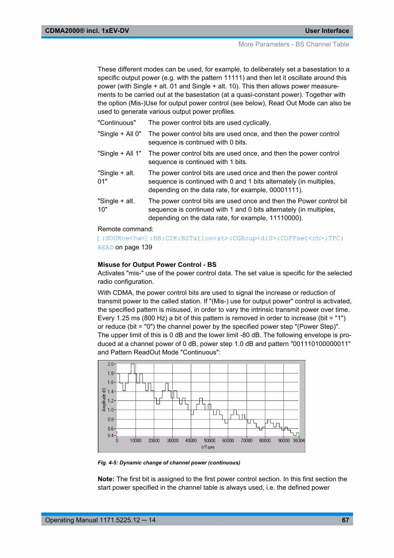
User InterfaceCDMA2000® incl. 1xEV-DV
67Operating Manual 1171.5225.12 ─ 14
These different modes can be used, for example, to deliberately set a basestation to aspecific output power (e.g. with the pattern 11111) and then let it oscillate around thispower (with Single + alt. 01 and Single + alt. 10). This then allows power measure-ments to be carried out at the basestation (at a quasi-constant power). Together withthe option (Mis-)Use for output power control (see below), Read Out Mode can also beused to generate various output power profiles.
"Continuous" The power control bits are used cyclically.
"Single + All 0" The power control bits are used once, and then the power controlsequence is continued with 0 bits.
"Single + All 1" The power control bits are used once, and then the power controlsequence is continued with 1 bits.
"Single + alt.01"
The power control bits are used once and then the power controlsequence is continued with 0 and 1 bits alternately (in multiples,depending on the data rate, for example, 00001111).
"Single + alt.10"
The power control bits are used once and then the Power control bitsequence is continued with 1 and 0 bits alternately (in multiples,depending on the data rate, for example, 11110000).
Remote command: [:SOURce<hw>]: BB: C2K:BSTation<st>: CGRoup<di0>: COFFset<ch>: TPC:READ on page 139
Misuse for Output Power Control - BSActivates "mis-" use of the power control data. The set value is specific for the selectedradio configuration.
With CDMA, the power control bits are used to signal the increase or reduction oftransmit power to the called station. If "(Mis-) use for output power" control is activated,the specified pattern is misused, in order to vary the intrinsic transmit power over time.Every 1.25 ms (800 Hz) a bit of this pattern is removed in order to increase (bit = "1")or reduce (bit = "0") the channel power by the specified power step "(Power Step)".The upper limit of this is 0 dB and the lower limit -80 dB. The following envelope is pro-duced at a channel power of 0 dB, power step 1.0 dB and pattern "001110100000011"and Pattern ReadOut Mode "Continuous":
Fig. 4-5: Dynamic change of channel power (continuous)
Note: The first bit is assigned to the first power control section. In this first section thestart power specified in the channel table is always used, i.e. the defined power
More Parameters - BS Channel Table

User InterfaceCDMA2000® incl. 1xEV-DV
68Operating Manual 1171.5225.12 ─ 14
change will be effective only in the next power control section (with the second powercontrol bit) .
Remote command: [:SOURce<hw>]: BB:C2K: BSTation<st>: CGRoup<di0>: COFFset<ch>: TPC: MISuse on page 138
Power Step (DPCCH) - BSSets the step width of the power change in dB for "(Mis-) use for output power control".The set value is specific for the selected radio configuration.
Remote command: [:SOURce<hw>]: BB:C2K: BSTation<st>: CGRoup<di0>: COFFset<ch>: TPC: PSTep on page 138
4.8.3 Channel Coding
The "Channel Coding" section or dialog "More Parameters" is where the channel cod-ing settings are made. The indicated values and the settings are specific for theselected radio configuration.
In contrast to 3GPP FDD, channel coding with CDMA2000 is part of the physical layer.The channel coding procedure may slightly vary depending on channel type, framelength and data rate.
Channel Coding Mode - More Params BSActivates or deactivates channel coding. The set state is specific for the selected radioconfiguration.
"Off" Channel coding is deactivated.Channel coding is not performed. The data sources of the individualchannels apply their data stream directly to the long-code scrambler.The data source supplies the traffic data with the data rate that wouldbe available at the long-code scrambler after coding is switched on.This effective data rate, which is used for reading off from the datasource, is displayed under Effective Data Rate. The Data Rateparameter displayed in the channel table continues to affect theEffective Data Rate, but no longer agrees with it.
"Complete" The complete channel coding is performed. The channel coding pro-cedure may slightly vary depending on channel type, frame lengthand data rate.
"Without Inter-leaving"
Except for the block interleaver, the whole channel coding procedureis carried out. In this mode the frame structure and the convolutionalcoder of an receiver can be tested.
"InterleavingOnly"
In this mode only a block interleaver is used for coding. This allowsthe deinterleaver in the receiver to be tested independently of theremaining (de-)coding process.
Remote command: [:SOURce<hw>]: BB: C2K:BSTation<st>: CGRoup<di0>: COFFset<ch>: CCODing: MODE on page 127
More Parameters - BS Channel Table

User InterfaceCDMA2000® incl. 1xEV-DV
69Operating Manual 1171.5225.12 ─ 14
Effective Data Rate - More Params BSIndication of the effective data rate. The indicated value is specific for the selectedradio configuration.
For coding modes "Interleaving Only" and "Coding Off" the effective data rate differsfrom the set data rate, since no increase in the data rate is brought about by the convo-lution coder. The data rate set in the channel table is therefore not correct.
For coding modes "Without Interleaving" and "Complete" the data rate in the channeltable agrees with the effective data rate, since there is an increase in the data rate dueto the convolution coder.
Remote command: [:SOURce<hw>]: BB: C2K:BSTation<st>: CGRoup<di0>: COFFset<ch>: CCODing: DATA:RATE? on page 126
Source Bits / Frame - More Params BSIndication of the number of input bits per frame for the channel coder. The indicatedvalue is specific for the selected radio configuration.
Remote command: [: SOURce<hw>]: BB:C2K: BSTation<st>: CGRoup<di0>: COFFset<ch>: CCODing: BITFrame? on page 125
CRC Length - More Params BSIndication of the CRC (cyclic redundancy code) type (length) for error identification.The indicated value is specific for the selected radio configuration.
Remote command: n.a.
Channel Coder Type - More Params BSSelects error protection. The set value is specific for the selected radio configuration.
Which coder types are available depends on the channel type and other channel set-tings such as frame length, etc.
If one of these parameters is changed so that the set channel coding type gets invalid,the next permissible value is automatically set.
"Off" No error protection. This selection is available for the pilot channelsonly.
"ConvEncoder"
Convolution Coder with generator polynomials defined by CDMA. Thenumeric value defines the rate of the convolution coder.
"TurboEncoder"
Turbo Coder of rate 1/3 in accordance with the CDMA specifications.The numeric value defines the rate of the turbo coder.
Remote command: [:SOURce<hw>]: BB: C2K:BSTation<st>: CGRoup<di0>: COFFset<ch>: CCODing: TYPE on page 128
More Parameters - BS Channel Table

User InterfaceCDMA2000® incl. 1xEV-DV
70Operating Manual 1171.5225.12 ─ 14
Symbol Repetition - More Params BSIndication of the symbol repetition rate. The indicated value is specific for the selectedradio configuration.
Symbol repetition is used together with block symbol puncture for adapting the convo-lutional or turbo coder output data rate to the required input data rate of the interleaver.
Remote command: [:SOURce<hw>]: BB: C2K:BSTation<st>: CGRoup<di0>: COFFset<ch>: CCODing: SREPetition? on page 128
Symbol Puncture - More Params BSIndication of the symbol puncture rate. The indicated value is specific for the selectedradio configuration.
Symbol puncturing (elimination) is used together with block symbol repetition for adapt-ing the convolutional or turbo coder output data rate to the required input data rate ofthe interleaver.
Remote command: [:SOURce<hw>]: BB: C2K:BSTation<st>: CGRoup<di0>: COFFset<ch>: CCODing: SPUNcture? on page 127
Block Interleaver - More Params BSDisplays the number of symbols that the interleaver processes per block. The indicatedvalue is specific for the selected radio configuration.
Remote command: [:SOURce<hw>]: BB: C2K:BSTation<st>: CGRoup<di0>: COFFset<ch>: CCODing: BINTerleaver? on page 125
4.8.4 Additional Sync Channel Parameters
In the "Additional Sync Channel Parameters" sections of the "More Params" dialog isavailable for the synchronisation channel F-SYNC and real time mode only.
CDMA Channel Number - More Params BSDisplays the CDMA Channel Number which corresponds to the RF.
Remote command: [:SOURce<hw>]: BB:C2K:BSTation: SYNC: CNUMber on page 122
More Parameters - BS Channel Table

User InterfaceCDMA2000® incl. 1xEV-DV
71Operating Manual 1171.5225.12 ─ 14
System Time - More Params BS(available for R&S SMBV and R&S WinIQSIM2 only)
Displays the system time.
Remote command: [:SOURce<hw>]: BB:C2K: BSTation: SYNC:STIMe on page 124
LC State (hex) - More Params BS(available for R&S SMBV and R&S WinIQSIM2 only)
Defines the long code state in hexadecimal format.
Remote command: [:SOURce<hw>]: BB:C2K:BSTation: SYNC: LCSTate on page 122
P_REV - More Params BSDisplays the Protocol Revision Level, i.e. specifies the CDMA2000 system releasenumber.
The table below gives the cross-reference between the P_REV values and theCDMA2000 Releases.
P_REV CDMA2000 Release
1 Korean PCS(Band Class4), USPCS(Band Class1)
2 IS-95
3 TBS74
4 IS-95A
5 IS-95B
6 IS2000 Release 0
7 IS2000 Release A
8 IS2000 Release B
Remote command: [:SOURce<hw>]: BB: C2K:BSTation: SYNC:PREV on page 123
MIN_P_REV - More Params BSDisplays the Minimum Protocol Revision Level.
The basestation sets this field to prevent mobile stations which can not be supportedby the basestation from accessing the CDMA system.
Remote command: [:SOURce<hw>]: BB: C2K:BSTation: SYNC: MPRev on page 123
SID - More Params BSDisplays the System Identification.
The basestation sets the system identification number.
Remote command: [:SOURce<hw>]: BB:C2K: BSTation: SYNC:SID on page 124
More Parameters - BS Channel Table

User InterfaceCDMA2000® incl. 1xEV-DV
72Operating Manual 1171.5225.12 ─ 14
NID - More Params BSDisplays the Network Identification.
The NID serves as a sub-identifier of a CDMA system as defined by the owner of theSID.
Remote command: [:SOURce<hw>]: BB: C2K:BSTation: SYNC: NID on page 123
4.8.5 Error Insertion
In the "Bit Error Insertion" and "Block Error Insertion" sections of the "More Params"dialog, errors can be inserted into the data source and into the CRC checksum, inorder, for example, to check the bit and block error rate testers.
These functions are available for realtime channels only.
Bit Error State - More Params BSActivates or deactivates bit error generation.
Bit errors are inserted into the data fields of the realtime channels.
When the data source is read out, individual bits are deliberately inverted at randompoints in the data bit stream with the specified error rate in order to simulate an invalidsignal.
Remote command: [:SOURce<hw>]: BB:C2K:BSTation<st>: CGRoup<di0>: COFFset<ch>: DERRor: BIT:STATe on page 132
Bit Error Rate - More Params BSSets the bit error rate.
Remote command: [: SOURce<hw>]: BB:C2K:BSTation<st>: CGRoup<di0>: COFFset<ch>: DERRor: BIT:RATE on page 131
Block Error State - More Params BSActivates or deactivates the block error generation.
The CRC checksum is determined and then the last bit is inverted at the specified errorprobability in order to simulate an invalid signal.
More Parameters - BS Channel Table

User InterfaceCDMA2000® incl. 1xEV-DV
73Operating Manual 1171.5225.12 ─ 14
Block error generation is only possible with channel coding enabled.
Remote command: [:SOURce<hw>]: BB:C2K: BSTation<st>: CGRoup<di0>: COFFset<ch>: DERRor:BLOCk: STATe on page 133
Block Error Rate - More Params BSSets the block error rate.
Remote command: [:SOURce<hw>]: BB:C2K: BSTation<st>: CGRoup<di0>: COFFset<ch>: DERRor:BLOCk: RATE on page 132
4.9 More Parameters for F-PDCH - BS
The "More Parameters" dialog for packet channel F-PDCH can be called in the BSchannel table in column "More Params" with button "Config...".
The settings for the packet channel F-PDCH channel and all other channels are differ-ent (see chapter 4.8, "More Parameters - BS Channel Table", on page 63 ). The dialogfor the special channels and the traffic channels is described below.
The channel coding for the F-PDCHs is always carried out in full (see 3GPP2C.S0002-C figure 3.1.3.1.1.1-19).
The parameters of both F-PDCCHs (such as Number of Slots per Subpacket, Sub-packet Position, etc.) are implicitly defined by the F-PDCH settings, since both thesechannels are always transmitted simultaneously with the F-PDCH. The "More Parame-ters" dialog for these F-PDCCHs is therefore mostly for display, it only enables theselection of channel coding mode.
The left part is used to enter the general settings for the packet channel.
The right, upper part contains a table for setting the parameters of the subpackets. Upto 8 subpackets can be transmitted for each regular packet.
The right, lower part displays the current configuration of the packet channel in graphi-cal form.
More Parameters for F-PDCH - BS

User InterfaceCDMA2000® incl. 1xEV-DV
74Operating Manual 1171.5225.12 ─ 14
4.9.1 General Settings for Packet Channel
Packet Interval - More Params F-PDCHs BSSelects the interval at which new data packets arrive.
New F-PDCH packets are generated in this interval. Within an interval, up to 8 sub-packets of a data packet can be transmitted with any required time offset.
The value range is dependent on the set sequence length (ARB settings). The values80 ms, 40 ms, 20 ms, 10 ms and 5 ms can always be set, and the maximum value is2000 ms. All intermediate values must satisfy the condition
Sequence Length = * 80ms/2^nwhere n is a whole number.
Example: Sequence length = one 80 ms frame.The possible values for the packet interval are 80 ms, 40 ms, 20 ms, 10 ms and 5 ms.Sequence length = three 80 ms frames.The possible values for the packet interval are 240 ms, 120 ms, 80 ms, 40 ms, 20 ms,10 ms and 5 ms.
Remote command: [:SOURce<hw>]: BB:C2K:BSTation<st>: PDCHannel: PINTerval on page 144
More Parameters for F-PDCH - BS

User InterfaceCDMA2000® incl. 1xEV-DV
75Operating Manual 1171.5225.12 ─ 14
Walsh Code Column Index - More Params F-PDCHs BSSelects the standard-compliant set of available Walsh codes for the F_PDCH (see3GPP2 C.S0003-C, table 2-35).
Remote command: [:SOURce<hw>]: BB: C2K:BSTation<st>: PDCHannel: WINDex on page 151
Same Packet Setup... - More Params F-PDCHs BSSets whether or not all subpackets are to be generated with the same settings.
In case "On" is selected, setting the packet parameters (Number of Bits etc., seebelow) can only be done for subpacket 1. All other subpackets receive the sameparameters.
The "Off" setting allows individual settings for each subpacket.
Remote command: [: SOURce<hw>]: BB:C2K:BSTation<st>: PDCHannel: PSETup on page 144
4.9.2 Subpacket Table Settings
The middle part contains a table for setting the parameters of the subpackets. Up to 8subpackets can be transmitted for each regular packet (Encoder Packet).
Subpacket Number - More Params F-PDCHs BSIndex number of the subpackets in the selected channel. Each packet can include upto eight subpackets.
The subpacket is selected by the suffix to SUBPacket in remote control.
Subpacket State - More Params F-PDCHs BSStatus of the subpacket.
Subpacket 1 is always active. The rest can be turned on and off.
Remote command: [:SOURce<hw>]: BB: C2K:BSTation<st>: PDCHannel: SUBPacket<di>: STATeon page 150
More Parameters for F-PDCH - BS

User InterfaceCDMA2000® incl. 1xEV-DV
76Operating Manual 1171.5225.12 ─ 14
Subpacket ID (SPID) - More Params F-PDCHs BSSelects the subpacket ID.
The subpacket ID controls the subpacket symbol selection and adopts one of four pos-sible subpackets from the encoder packet.
The ID of the first subpacket is fixed at 0. The ID can be chosen for each of the rest.
Remote command: [:SOURce<hw>]: BB:C2K:BSTation<st>: PDCHannel: SUBPacket<di>: IDon page 145
Time Slot Offset - More Params F-PDCHs BSSets the starting time of the subpacket relative to the starting time of the packet inter-val.
The first subpacket always has an offset of 0, which cannot be changed.
The value range for the individual subpackets depends on the settings of the othersubpackets:
The time slot offsets of the remaining subpackets must be entered in ascending order.Also it is not permitted to transmit two packets simultaneously.
Example: Subpacket 2 is transmitted in time slot 5 and is 4 slots long. Subpacket 3 can only betransmitted in time slot 9 and no sooner.In total the value range is 0 to (Packet Interval/1.25 ms -Number of Slots per Sub-packet).
Example: Packet Interval = 20 ms, Number of Slots per Subpacket = 2. The value range is 0 to14.The entry for "Number of Slots per Subpacket" defines the length of a packet.
Remote command: [:SOURce<hw>]: BB:C2K: BSTation<st>: PDCHannel: SUBPacket<di>: TOFFset on page 151
PDCH Subpacket Table Parameters - More Params F-PDCHs BSOnly certain combinations of this parameter with the parameters of the last five tablecolumns are possible. These combinations are shown in the selection list in the form ofa table for all five parameters.
More Parameters for F-PDCH - BS

User InterfaceCDMA2000® incl. 1xEV-DV
77Operating Manual 1171.5225.12 ─ 14
"Number of Bits per Encoder Packet"Sets the number of bits per encoder packet.The "Number of Bits per Encoder Packet" defines the number of databits that can be read from the data source for an encoder packet. Dueto the channel coding this number is multiplied by a factor of about 5.The subsequent subpacket symbol selection then divides these bitsinto four different subpackets which can be selected via the SPIDparameter.The "Number of Bits per Encoder Packet" can only be changed forsubpacket 1. This value must be identical for the remaining subpack-ets, since they are all part of a single encoder packet.
"Number of 32-Chip Walsh Channels"Selects the number of 32-chip Walsh channels.
"Subpacket Data Rate (kbps)"Selects the data rate of the subpacket.The data rate is the result of the "Number of Bits per Encoder Packet"divided by the duration of the subpacket (= "Number of Slots per Sub-packet"). Therefore only specified combinations of the "SubpacketData Rate" with the "Number of Slots per Subpacket" at a specified"Number of Bits per Encoder Packet" are possible.
"Number of Slots per Subpacket"Selects the number of slots per subpacket. This parameter definesthe duration of the subpacket. A slot equals 1.25 ms.The "Number of Slots per Subpacket" is the result of the "Number ofBits per Encoder Packet" divided by the data rate. Therefore onlyspecified combinations of the Subpacket Data Rate with the "Numberof Slots per Subpacket" at a specified "Number of Bits per EncoderPacket" are possible.
"Modulation" Indication of the modulation type.The modulation type is fix for each combination of the above parame-ters.
Remote command: [:SOURce<hw>]: BB: C2K:BSTation<st>: PDCHannel: SUBPacket<di>: PARameters on page 145
More Parameters for F-PDCH - BS

User InterfaceCDMA2000® incl. 1xEV-DV
78Operating Manual 1171.5225.12 ─ 14
Resulting Walsh Codes for Subpacket - More Params F-PDCHs BSIndication of the resulting Walsh codes for the sub packet.
Remote command: [:SOURce<hw>]: BB:C2K: BSTation<st>: PDCHannel: SUBPacket<di>: WCODes? on page 151
4.9.3 Subpacket Graph
The current configuration of the packet channel and its active subpackets is displayedin graphical form below the table.
The X axis is the length of the set packet interval in ms, i.e. the duration of the trans-mission of an encoder packet.
The relative power of the subpackets is represented on the Y axis. The subpackets areshown as bars and are 1, 2 or 4 time slots wide according to the configuration. Theposition on the X axis corresponds to the selected time slot offset.
The color of the bar depends on the sub packet ID (SPID). The assignment of colors toSPIDs is shown below the graph.
4.10 Mobile Station Configuration (MS)
The "Mobile Station Configuration" dialog is called by selecting mobile station "MS1 ...MS4" in the CDMA2000 dialog.
Mobile station 1 (MS1) generates all the channels in realtime, the other mobile stationsgenerate the channels in arbitrary waveform mode.
The dialog is divided into the sections "Common Settings", "Power Control" and "Chan-nel Table".
The structure of the channel table depends on the selected operating mode and - forthe traffic channel - on the selected radio configuration.
Mobile Station Configuration (MS)

User InterfaceCDMA2000® incl. 1xEV-DV
79Operating Manual 1171.5225.12 ─ 14
4.10.1 Common Settings - MS
The "Common Settings" section is where the general settings for the selected mobilestation are made.
State - MSActivates or deactivates the selected mobile station. The number of the selectedmobile station is specified in the dialog header.
Remote command: [:SOURce<hw>]: BB: C2K:MSTation<st>: STATe on page 164
Operating Mode - MSSelects the mode in which the mobile station is to work.
The operating mode defines the generated channel types. The lower part of the dialogwill change in accordance with the mode. The following modes are available:
"Traffic" In this mode the instrument generates a single traffic channel. A traf-fic channel consists of up to 8 sub channels depending on theselected radio configuration.This mode corresponds to the standard mode of a mobile station dur-ing voice and data transmission.
"Access" In this mode, the instrument generates an access channel (R-ACH).This channel is needed to set up the connection between the mobilestation and the base station.
"EnhancedAccess"
In this mode, the instrument generates an enhanced access channel(R-ACH) and a pilot channel (R-PICH). These channels are used toset up the connection between the mobile station and the basesta-tion.
"CommonControl"
In this mode, the instrument generates a common control channel (R-ACH) and a pilot channel (R-PICH).
Remote command: [:SOURce<hw>]: BB: C2K:MSTation<st>: MODE on page 163
Radio Configuration - MSSelects the radio configuration for the traffic channel.
Mobile Station Configuration (MS)

User InterfaceCDMA2000® incl. 1xEV-DV
80Operating Manual 1171.5225.12 ─ 14
In the reverse link, the channel scenario with the spreading codes of the individualchannels is predefined by selecting the radio configuration. For this reason the channeltable does not contain selection parameters for the Walsh code.
A separate set of settings of all channel table parameters is provided for each radioconfiguration. Changing the radio configuration causes the settings belonging to thenew RC value to be activated in the channel table (the settings belonging to the old RCvalue are not lost).
The radio configuration determines the permissible frame lengths and the frame lengthdefines the permitted data rate.
Changing the frame length automatically causes the data rate to be changed if it is nolonger permitted.
Remote command: [:SOURce<hw>]: BB:C2K: MSTation<st>: RCONfiguration on page 163
Channel Coding - MSActivates or deactivates channel coding.
"Off" Channel coding is deactivated.
"Complete" The complete channel coding is performed. The channel coding pro-cedure may slightly vary depending on channel type, frame lengthand data rate.
"Without Inter-leaving"
Except for the block interleaver, the whole channel coding procedureis carried out.
"InterleavingOnly"
In this mode only block interleaver is used for coding.
Remote command: [:SOURce<hw>]: BB: C2K:MSTation<st>: CCODing: MODE on page 157
LC Mask (hex) - MSEnters the mask of the long-code generator in hexadecimal form.
The long-code mask is a 42-bit value. The mask serves for channel-specific and user-specific scrambling of the code channel. The value range is 0 to 3FF FFFF FFFF.
Remote command: [:SOURce<hw>]: BB: C2K:MSTation<st>: LCMask on page 163
4.10.2 Power Control - MS
The "Power Control" section is where the settings for the power control bits are made.
In the uplink, the bits are used exclusively for controlling the mobile station outputpower by activating the "Mis(use) Power Control" function. Power control puncturing ofthe data bits of the traffic channels for controlling the base station power is not per-formed.
This section is only available for the traffic channel.
Mobile Station Configuration (MS)

User InterfaceCDMA2000® incl. 1xEV-DV
81Operating Manual 1171.5225.12 ─ 14
Data Source (Power Control) - MSDefines the data source for the power control bits of the channel.
The following standard data sources are available:● "All 0, All 1"
An internally generated sequence containing 0 data or 1 data.● "PNxx"
An internally generated pseudo-random noise sequence.● "Pattern"
An internally generated sequence according to a bit pattern.Use the "Pattern" box to define the bit pattern.
● "Data List/Select DList"A binary data from a data list, internally or externally generated.Select "Select DList" to access the standard "Select List" dialog.– Select the "Select Data List > navigate to the list file *.dm_iqd > Select" to
select an existing data list.– Use the "New" and "Edit" functions to create internally new data list or to edit
an existing one.– Use the standard "File Manager" function to transfer external data lists to the
instrument.See also "Main Dialog > Data List Management".
Remote command: [:SOURce<hw>]: BB:C2K:MSTation<st>: TPC:DATA on page 164[:SOURce<hw>]: BB:C2K:MSTation<st>: TPC:DATA:PATTern on page 165[:SOURce<hw>]: BB:C2K:MSTation<st>: TPC:DATA:DSELect on page 165
Read Out Mode (Power Control) - MSDefines a read-out mode of power control bits.
Together with the option (Mis-)Use for output power control (see below), Read OutMode can also be used to generate various output power profiles.
"Continuous" The power control bits are used cyclically.
"Single + All 0" The power control bits are used once and then the power controlsequence is continued with 0 bits.
"Single + All 1" The power control bits are used once and then the power controlsequence is continued with 1 bits.
"Single + alt.01"
The power control bits are used once and then the power controlsequence is continued with 0 and 1 bits alternately.
"Single + alt.10"
The power control bits are used once and then the power controlsequence is continued with 1 and 0 bits alternately.
Remote command: [:SOURce<hw>]: BB: C2K:MSTation<st>: TPC: READ on page 166
Misuse for Output Power Control - MSActivates "mis-" use of the power control data.
In the uplink, the power control bits are used exclusively for controlling the mobile sta-tion output power. Power control puncturing is not defined for controlling the basesta-tion power
Mobile Station Configuration (MS)

User InterfaceCDMA2000® incl. 1xEV-DV
82Operating Manual 1171.5225.12 ─ 14
If "(Mis-) use for output power control" is activated, the specified pattern is used to varythe intrinsic transmit power over time. Every 1.25 ms (800 Hz) a bit of this pattern isremoved in order to increase (bit = "1") or reduce (bit = "0") the channel power by thespecified power step "(Power Step)". The upper limit for this is 0 dB and the lower limit-80 dB. The following envelope is produced at a channel power of 0 dB, power step1.0 dB and pattern "001110100000011" and Pattern ReadOut Mode "Continuous":
Fig. 4-6: Dynamic change of channel power (continuous)
Note: The first bit is assigned to the first power control section. In this first section thestart power specified in the channel table is always used, i.e. only in the next powercontrol section (with the second power control bit) will the defined power change beeffective.
Remote command: [:SOURce<hw>]: BB:C2K: MSTation<st>: TPC:MISuse on page 165
Power Step - MSSets the step width of the power change in dB for "(Mis-) use for output power control".
Remote command: [:SOURce<hw>]: BB:C2K:MSTation<st>: TPC:PSTep on page 166
4.10.3 Channel Table - MS
The "channel table" is located in the lower part of the dialog. The channel table iswhere the individual channel parameters are set.
The structure of the channel table depends on the selected operating mode and - forthe traffic channel - on the selected radio configuration. Also, for the traffic channels,the indicated values and the settings are specific for the selected radio configuration.
In uplink, the employed Walsh code is determined by the radio configuration and can-not be chosen.
The following combinations between the operating modes of the four mobile stationsare allowed:
Mobile Station Configuration (MS)

User InterfaceCDMA2000® incl. 1xEV-DV
83Operating Manual 1171.5225.12 ─ 14
Traffic,RC1 &RC 2
Traffic, RC3 &RC 4
Access EnhancedAccess
Common Con-trol
Traffic, RC1 &RC 2
X X
Traffic, RC3 &RC 4
X X X
Access X X
EnhancedAccess
X X X
Common Con-trol
X X X
Channel Number- MSDisplays the channel number.
All channels of the selected operating mode are listed. The channels are switched onand off with the "On/Off" button in the "State" column.
Remote command: n.a.
Channel Type - MSIndication of the channel type (see table 4-3). The possible channel types depend onthe selected operating mode of the mobile station.Table 4-3: List of supported channel types
Short form Name Function
Traffic
R-PICH Reverse Pilot Channel The Reverse Pilot Channel pro-vides the capabilities for coherentdetection.
R-DCCH Reverse Dedicated Control Chan-nel
The Reverse Dedicated ControlChannel transports mobile-spe-cific control information.
R-FCH Reverse Fundamental Channel The Reverse Fundamental Chan-nel is similar to F-FCH; designedto transport dedicated data.
R-SCH Reverse Supplemental Channel(RC 3...5)
The Reverse Supplemental Chan-nels are allocated dynamically tomeet a required data rate.
R-SCCH Reverse Supplemental CodeChannel (RC 1 / 2)
The Reverse Supplemental CodeChannels are allocated dynami-cally to meet a required data rate.
Access
R-ACH Reverse Access Channel The Access channel is needed toset up the connection betweenthe mobile station and the basestation.
Mobile Station Configuration (MS)

User InterfaceCDMA2000® incl. 1xEV-DV
84Operating Manual 1171.5225.12 ─ 14
Short form Name Function
Enhanced Access
R-EACH Reverse Enhanced Access Chan-nel
The Reverse Enhanced AccessChannel is needed to set up theconnection between the mobilestation and the base station
R-PICH Reverse Pilot Channel The Reverse Pilot Channel pro-vides the capabilities for coherentdetection.
Common Control
R-CCCH Reverse Common Control Chan-nel
The Reverse Fundamental Chan-nel is similar to R-ACH but it ismeant to transport control infor-mation.
Remote command: [:SOURce<hw>]: BB: C2K:MSTation<st>: CHANnel<ch>: TYPE? on page 161
Frame Length- MSEnters the frame length of the channel. For the traffic channels, the indicated value isspecific for the selected radio configuration.
The value range depends on the channel type and the selected radio configuration.The frame length of some channels is fixed. The maximum frame length is 80 ms, theminimum frame length is 5 ms.
The frame length affects the data rates that are possible within a channel. If a framelength is changed so that the set data rate becomes invalid, the next permissible valueis automatically set.
Remote command: [: SOURce<hw>]: BB:C2K:MSTation<st>: CHANnel<ch>: FLENgth on page 160
Data Rate - MSEnters the data rate of the channel. For the traffic channels, the indicated value is spe-cific for the selected radio configuration.
The R&S Signal Generator supports all data rates between 1.2 kbps and 1,036.8 kbpsdefined in the standard.
The value range depends on the frame length. If one of these parameters is changedso that the set data rate becomes invalid, the next permissible value is automaticallyset.
Remote command: [:SOURce<hw>]: BB: C2K:MSTation<st>: CHANnel<ch>: DATA: RATEon page 159
Walsh - MSAssigns the Walsh Code to the channel (see chapter 3.9, "Spreading - Uplink",on page 14). For the traffic channels, the indicated value is specific for the selectedradio configuration.
Mobile Station Configuration (MS)

User InterfaceCDMA2000® incl. 1xEV-DV
85Operating Manual 1171.5225.12 ─ 14
The code channel is spread with the set Walsh code (spreading code). The Walshcodes to be used are specified by the standard and cannot be chosen.
Remote command: [:SOURce<hw>]: BB:C2K: MSTation<st>: CHANnel<ch>: WCODe? on page 162
Spread- MSIndication of the spreading factor of the channel. For the traffic channels, the indicatedvalue is specific for the selected radio configuration.
The spreading factor corresponds to the length of the employed Walsh code. TheWalsh codes to be used are specified by the standard and cannot be chosen.
Remote command: [:SOURce<hw>]: BB:C2K: MSTation<st>: CHANnel<ch>: SPReading? on page 160
Power - MSEnters the channel power in dB. For the traffic channels, the set value is specific forthe selected radio configuration.
The power entered is relative to the power's output of the other channels. If "AdjustTotal Power to 0 dB" is executed (top level of the CDMA2000 dialog), all the powerdata is relative to 0 dB.
The set power value is also the start power of the channel for "Misuse For OutputPower Control".
Note: The maximum channel power of 0 dB applies to non-blanked channels (dutycycle 100%), with blanked channels, the maximum value can be increased (by AdjustTotal Power) to values greater than 0 dB (to 1ß*log10(1/duty_cycle)).
Remote command: [:SOURce<hw>]: BB:C2K: MSTation<st>: CHANnel<ch>: POWer on page 160
Data - MSSelects data source. For the traffic channels, the set value is specific for the selectedradio configuration.
The following standard data sources are available:● "All 0, All 1"
An internally generated sequence containing 0 data or 1 data.● "PNxx"
An internally generated pseudo-random noise sequence.● "Pattern"
An internally generated sequence according to a bit pattern.Use the "Pattern" box to define the bit pattern.
● "Data List/Select DList"A binary data from a data list, internally or externally generated.Select "Select DList" to access the standard "Select List" dialog.– Select the "Select Data List > navigate to the list file *.dm_iqd > Select" to
select an existing data list.– Use the "New" and "Edit" functions to create internally new data list or to edit
an existing one.
Mobile Station Configuration (MS)

User InterfaceCDMA2000® incl. 1xEV-DV
86Operating Manual 1171.5225.12 ─ 14
– Use the standard "File Manager" function to transfer external data lists to theinstrument.
See also "Main Dialog > Data List Management".
Remote command: [:SOURce<hw>]: BB:C2K: MSTation<st>: CHANnel<ch>: DATA on page 157[:SOURce<hw>]: BB:C2K: MSTation<st>: CHANnel<ch>: DATA: PATTernon page 159[:SOURce<hw>]: BB:C2K: MSTation<st>: CHANnel<ch>: DATA: DSELecton page 158
Channel State- MSActivates/deactivates the channel. For the traffic channels, the indicated value is spe-cific for the selected radio configuration.
Remote command: [:SOURce<hw>]: BB: C2K:MSTation<st>: CHANnel<ch>: STATe on page 161
Mobile Station Configuration (MS)

Remote-Control CommandsCDMA2000® incl. 1xEV-DV
87Operating Manual 1171.5225.12 ─ 14
5 Remote-Control CommandsThe following commands are required to perform signal generation with theCDMA2000 options in a remote environment. We assume that the R&S Signal Genera-tor has already been set up for remote operation in a network as described in theR&S Signal Generator documentation. Knowledge of the remote control operation andthe SCPI command syntax is assumed.
Conventions used in SCPI command descriptionsFor a description of the conventions used in the remote command descriptions, seesection "Remote Control Commands" in the R&S Signal Generator operating manual.
The commands in the SOURce:BB:C2K subsystem are described in several sections,separated into general remote commands, commands for base station settings andcommands for mobile station settings.
Common Suffixes
The following common suffixes are used in remote commands:
Suffix Value range Description
SOURce<hw> [1]|2 available baseband signals
OUTPut<ch> 1 .. 4 available markers
R&S SMBV supports two markers
EXTernal<ch> 1|2 external trigger connectors
Placeholder <root>
For commands that read out or save files in the default directory, the default directoryis set using command MMEM:CDIRectory. The examples in this description use theplace holder <root> in the syntax of the command.
● D:\ - for selecting the internal hard disk of a Windows instrument
● E:\ - for selecting the memory stick which is inserted at the USB interface of aWindows instrument
● /var/user/ - for selecting the internal flash card of a Linux instrument
● /usb/ - for selecting the memory stick which is inserted at the USB interface of aLinux instrument.

Remote-Control CommandsCDMA2000® incl. 1xEV-DV
88Operating Manual 1171.5225.12 ─ 14
Tasks (in manual or remote operation) that are also performed in the base unit in thesame way are not described here.In particular, this includes:● Managing settings and data lists, i.e. storing and loading settings, creating and
accessing data lists, accessing files in a particular directory, etc.● Information on regular trigger, marker and clock signals as well as filter settings, if
appropriate.● General instrument configuration, such as configuring networks and remote opera-
tion● Using the common status registers
For a description of such tasks, see the R&S Signal Generator operating manual.
The following commands specific to the CDMA2000 are described here:
5.1 Primary Commands
[:SOURce<hw>]:BB:C2K:COPY:COFFset.......................................................................... 88[:SOURce<hw>]:BB:C2K:COPY:DESTination..................................................................... 89[:SOURce<hw>]:BB:C2K:COPY:EXECute.......................................................................... 89[:SOURce<hw>]:BB:C2K:COPY:SOURce...........................................................................90[:SOURce<hw>]:BB:C2K:CRATe?..................................................................................... 90[:SOURce<hw>]:BB:C2K:CRATe:VARiation........................................................................90[:SOURce<hw>]:BB:C2K:IQSWap[:STATe].........................................................................91[:SOURce<hw>]:BB:C2K:LINK.......................................................................................... 91[:SOURce<hw>]:BB:C2K:POWer:ADJust............................................................................91[:SOURce<hw>]:BB:C2K:POWer[:TOTal]?......................................................................... 92[:SOURce<hw>]:BB:C2K:PRESet......................................................................................92[:SOURce<hw>]:BB:C2K:SETTing:CATalog?......................................................................92[:SOURce<hw>]:BB:C2K:SETTing:DELete......................................................................... 93[:SOURce<hw>]:BB:C2K:SETTing:LOAD........................................................................... 93[:SOURce<hw>]:BB:C2K:SETTing:STORe......................................................................... 93[:SOURce<hw>]:BB:C2K:SETTing:STORe:FAST................................................................ 94[:SOURce<hw>]:BB:C2K:SLENgth.....................................................................................94[:SOURce<hw>]:BB:C2K:STATe....................................................................................... 94[:SOURce<hw>]:BB:C2K:WAVeform:CREate......................................................................95[:SOURce]:BB:C2K:VERSion?...........................................................................................95
[:SOURce<hw>]:BB:C2K:COPY:COFFset <COffset>
The command sets the offset for the Walsh code in the destination base station. Theminimum value is 0 (Walsh codes are identical), the maximum value is 255.
This command is only available in the downlink (SOUR:BB:C2K:LINK FORW/DOWN).
Primary Commands

Remote-Control CommandsCDMA2000® incl. 1xEV-DV
89Operating Manual 1171.5225.12 ─ 14
Parameters:<COffset> integer
Range: 0 to 255Increment: 1*RST: 0
Example: BB:C2K:COPY:COFF 10the Walsh code is shifted by 10 when the source base station iscopied to the destination base station.
Manual operation: See "Copy ..." on page 29
[:SOURce<hw>]:BB:C2K:COPY:DESTination <Destination>
The command selects the station to which data is to be copied. Whether the data iscopied to a base station or a mobile station depends on which transmission direction isselected (command C2K:LINK UP | DOWN).
Parameters:<Destination> 1 | 2 | 3 | 4
Range: 1 to 4*RST: 2
Example: BB:C2K:LINK DOWNselects the downlink transmit direction (base station to mobilestation).BB:C2K:COPY:SOUR 1selects base station 1 as the source.BB:C2K:COPY:DEST 4selects base station 4 as the destination.BB:C2K:COPY:EXECstarts copying the parameter set of base station 1 to base sta-tion 4.
Manual operation: See "Copy ..." on page 29
[:SOURce<hw>]:BB:C2K:COPY:EXECute
The command starts the copy process. The dataset of the source station is copied tothe destination station. Whether the data is copied to a base station or a mobile stationdepends on which transmission direction is selected (command :BB:C2K:LINK UP |DOWN).
Example: BB:C2K:COPY:EXECstarts copying the parameter set of the selected source stationto the selected destination station.
Usage: Event
Manual operation: See "Copy ..." on page 29
Primary Commands

Remote-Control CommandsCDMA2000® incl. 1xEV-DV
90Operating Manual 1171.5225.12 ─ 14
[:SOURce<hw>]:BB:C2K:COPY:SOURce <Source>
The command selects the station that has data to be copied. Whether the station cop-ied is a base or mobile station depends on which transmission direction is selected(command C2K:LINK UP | DOWN).
Parameters:<Source> 1 | 2 | 3 | 4
Range: 1 to 4*RST: 1
Example: BB:C2K:LINK UPselects the uplink transmit direction (mobile station to base sta-tion).BB:C2K:COPY:SOUR 1selects mobile station 1 as the source.BB:C2K:COPY:DEST 4selects mobile station 4 as the destination.BB:C2K:COPY:EXECstarts copying the parameter set of mobile station 1 to mobilestation 4.
Manual operation: See "Copy ..." on page 29
[:SOURce<hw>]:BB:C2K:CRATe?
The command queries the spreading rate. The output chip rate which determines therate of the spread symbols as is used for signal output can be set with the commandSOUR:BB:C2K:CRAT:VAR.
Return values: <CRate> R1M2
*RST: R1M2
Example: BB:C2K:CRAT?queries the system chip rate.Response:R1M2the system chip rate is 1.2288 Mcps.
Usage: Query only
Manual operation: See "Spreading Rate" on page 25
[:SOURce<hw>]:BB:C2K:CRATe:VARiation <Variation>
The command enters the output chip rate.
The output chip rate changes the output clock and the modulation bandwidth, as wellas the synchronization signals that are output. It does not affect the calculated chipsequence.
Primary Commands

Remote-Control CommandsCDMA2000® incl. 1xEV-DV
91Operating Manual 1171.5225.12 ─ 14
Parameters:<Variation> float
Range: 1 Mcps to 5 McpsIncrement: 1 Hz*RST: 1.2288 Mcps
Example: BB:C2K:CRAT:VAR 4086001sets the chip rate to 4.08 Mcps.
Manual operation: See "Chip Rate Variation" on page 32
[:SOURce<hw>]:BB:C2K:IQSWap[:STATe] <State>
This command inverts the Q-part of the baseband signal if set to ON. The signal on thebaseband outputs meets the cdma2000 standard. In order to generate an RF signalthat conforms to the standard, the "I/Q Swap" function in the "I/Q Modulator" menumust be enabled ("On") (SOURce:IQ:SWAP ON).
Parameters:<State> 0 | 1 | OFF | ON
*RST: OFF
Example: BB:C2K:IQSW:STAT ONinverts the Q-part of the baseband signal.
Manual operation: See "Invert Q for Correct Baseband Output" on page 36
[:SOURce<hw>]:BB:C2K:LINK <Link>
The command defines the transmission direction. The signal either corresponds to thatof a base station (FORWard | DOWN) or that of a mobile station (REVerse | UP).
Parameters:<Link> DOWN | UP | FORWard | REVerse
*RST: DOWN
Example: BB:C2K:LINK DOWNthe transmission direction selected is base station to mobile sta-tion. The signal corresponds to that of a base station.
Manual operation: See "Link Direction" on page 26
[:SOURce<hw>]:BB:C2K:POWer:ADJust
The command sets the power of the active channels in such a way that the total powerof the active channels is 0 dB. This will not change the power ratio among the individ-ual channels.
Example: BB:C2K:POW:ADJthe total power of the active channels is set to 0 dB, the powerratio among the individual channels is unchanged.
Usage: Event
Primary Commands

Remote-Control CommandsCDMA2000® incl. 1xEV-DV
92Operating Manual 1171.5225.12 ─ 14
Manual operation: See "Adjust Total Power to 0dB" on page 29
[:SOURce<hw>]:BB:C2K:POWer[:TOTal]?
The command queries the total power of the active channels. After "Power Adjust", thispower corresponds to 0 dB.
Return values: <Total> float
Range: -80 dB to 30 dBIncrement: 0.01 dB*RST: 0 dB
Example: BB:C2K:POW?queries the total power of the active channels.Response: -22.5the total power is -25 dB.
Usage: Query only
Manual operation: See "Total Power " on page 30
[:SOURce<hw>]:BB:C2K:PRESet
The command produces a standardized default for the CDMA2000 standard. The set-tings correspond to the *RST values specified for the commands.
All CDMA2000 settings are preset.
Example: BB:C2K:PRESresets all the CDMA2000 settings to default values.
Usage: Event
Manual operation: See "Set to Default" on page 22
[:SOURce<hw>]:BB:C2K:SETTing:CATalog?
This command reads out the files with CDMA2000 settings in the default directory. Thedefault directory is set using command MMEM:CDIRectory. Only files with the fileextension *.cdma2k will be listed.
Return values: <Catalog> string
Example: MMEM:CDIR "<root>cdma"sets the default directory to <root>cdma.BB:C2K:SETT:CAT?reads out all the files with CDMA2000 settings in the defaultdirectory.Response: 'CDMA_UP','CDMA_DN'the files CDMA_UP and CDMA_DN are available.
Primary Commands

Remote-Control CommandsCDMA2000® incl. 1xEV-DV
93Operating Manual 1171.5225.12 ─ 14
Usage: Query only
Manual operation: See "Save/Recall ..." on page 23
[:SOURce<hw>]:BB:C2K:SETTing:DELete <Filename>
This command deletes the selected file with CDMA2000 settings. The directory is setusing command MMEM:CDIRectory. A path can also be specified, in which case thefiles in the specified directory are read. The file extension may be omitted. Only fileswith the file extension *.cdma2k will be deleted.
Setting parameters: <Filename> string
Example: BB:C2K:SETT:DEL 'CDMA_UPdeletes file CDMA_UP.
Usage: Setting only
Manual operation: See "Save/Recall ..." on page 23
[:SOURce<hw>]:BB:C2K:SETTing:LOAD <Filename>
This command loads the selected file with CDMA2000 settings. The directory is setusing command MMEM:CDIRectory. A path can also be specified, in which case thefiles in the specified directory are read. The file extension may be omitted. Only fileswith the file extension *.cdma2k will be loaded.
Setting parameters: <Filename> string
Example: BB:C2K:SETT:LOAD 'CDMA_UP'loads file CDMA_UP.
Usage: Setting only
Manual operation: See "Save/Recall ..." on page 23
[:SOURce<hw>]:BB:C2K:SETTing:STORe <Filename>
This command stores the current CDMA2000 settings into the selected file. The direc-tory is set using command MMEM:CDIRectory. A path can also be specified, in whichcase the files in the specified directory are read. Only the file name has to be entered.CDMA2000 settings are stored as files with the specific file extensions *.cdma2k.
Setting parameters: <Filename> string
Example: BB:C2K:SETT:STOR 'CDMA_UP'stores the current CDMA2000 settings into file CDMA_UP.
Usage: Setting only
Manual operation: See "Save/Recall ..." on page 23
Primary Commands
Remote-Control CommandsCDMA2000® incl. 1xEV-DV
94Operating Manual 1171.5225.12 ─ 14
[:SOURce<hw>]:BB:C2K:SETTing:STORe:FAST <Fast>
Determines whether the instrument performs an absolute or a differential storing of thesettings.
Enable this function to accelerate the saving process by saving only the settings withvalues different to the default ones.
Note: This function is not affected by the "Preset" function.
Parameters:<Fast> 0 | 1 | OFF | ON
*RST: ON
Manual operation: See "Save/Recall ..." on page 23
[:SOURce<hw>]:BB:C2K:SLENgth <SLength>
The command sets the sequence length of the arbitrary waveform component of theCDMA2000 signal in the number of frames. This component is calculated in advanceand output in the arbitrary waveform generator. It is added to the realtime signal com-ponents.
Parameters:<SLength> float
Range: 1 frame to 511 frames*RST: 1
Example: BB:C2K:SLEN 10sets the sequence length to 10 frames.
Manual operation: See "Sequence Length ARB" on page 36
[:SOURce<hw>]:BB:C2K:STATe <State>
The command activates modulation in accordance with the CDMA2000 standard. Acti-vating this standard deactivates all the other digital standards and digital modulationmodes (in case of two-path instruments, this affects the same path).
BB:C2K:STAT ON deactivates the other standards and digital modulation.
Parameters:<State> 0 | 1 | OFF | ON
*RST: OFF
Example: BB:C2K:STAT ONactivates modulation in accordance with the CDMA2000 stand-ard.
Manual operation: See "State" on page 22
Primary Commands

Remote-Control CommandsCDMA2000® incl. 1xEV-DV
95Operating Manual 1171.5225.12 ─ 14
[:SOURce<hw>]:BB:C2K:WAVeform:CREate <Filename>
This command creates a waveform using the current settings of the "CDMA2000"menu. The file name is entered with the command. The file is stored with the prede-fined file extension *.wv. The file name and the directory it is stored in are user-defina-ble.
Setting parameters: <Filename> string
Example: MMEM:CDIR "<root>waveform"sets the default directory to <root>waveform.BB:C2K:WAV:CRE "cdma_bs"creates the waveform file cdma_bs.wv in the default directory.
Usage: Setting only
Manual operation: See "Generate Waveform File" on page 25
[:SOURce]:BB:C2K:VERSion?
The command queries the version of the CDMA standard underlying the definitions.
Return values: <Version> string
Example: BB:C2K:VERS?queries the CDMA version.Response: Release CCDMA Release 5
Usage: Query only
Manual operation: See "CDMA 2000 Version" on page 25
5.2 Filter/Clipping Settings
5.2.1 Filter Settings
[:SOURce<hw>]:BB:C2K:FILTer:TYPe...............................................................................96[:SOURce<hw>]:BB:C2K:FILTer:ILENgth........................................................................... 96[:SOURce<hw>]:BB:C2K:FILTer:ILENgth:AUTO................................................................. 96[:SOURce<hw>]:BB:C2K:FILTer:OSAMpling.......................................................................97[:SOURce<hw>]:BB:C2K:FILTer:OSAMpling:AUTO.............................................................97[:SOURce<hw>]:BB:C2K:FILTer:PARameter:APCO25.........................................................97[:SOURce<hw>]:BB:C2K:FILTer:PARameter:COSine.......................................................... 97[:SOURce<hw>]:BB:C2K:FILTer:PARameter:GAUSs...........................................................98[:SOURce<hw>]:BB:C2K:FILTer:PARameter:LPASs............................................................98[:SOURce<hw>]:BB:C2K:FILTer:PARameter:LPASSEVM....................................................98
Filter/Clipping Settings

Remote-Control CommandsCDMA2000® incl. 1xEV-DV
96Operating Manual 1171.5225.12 ─ 14
[:SOURce<hw>]:BB:C2K:FILTer:PARameter:PGAuss..........................................................99[:SOURce<hw>]:BB:C2K:FILTer:PARameter:RCOSine........................................................99[:SOURce<hw>]:BB:C2K:FILTer:PARameter:SPHase..........................................................99
[:SOURce<hw>]:BB:C2K:FILTer:TYPe <Type>
The command selects the filter type.
Parameters:<Type> RCOSine | COSine | GAUSs | LGAuss | CONE | COF705 |
COEQualizer | COFequalizer | C2K3x | APCO25 | SPHase |RECTangle | PGAuss | LPASs | DIRac | ENPShape |EWPShape | LPASSEVM*RST: Downlink:COEF; Uplink: CONE
Example: BB:C2K:FILT:TYPE CONEsets the filter type CdmaOne. This filter type is defined by thestandard for the uplink.
Manual operation: See "Filter" on page 31
[:SOURce<hw>]:BB:C2K:FILTer:ILENgth <ILength>
(available for R&S WinIQSIM2 only)
The command sets the impulse length (number of filter tabs).
Parameters:<ILength> integer
Range: 1 to 128Increment: 1*RST: 10
Example: BB:C2K:FILT:ILEN 10sets the number of filter tabs to 10.
Manual operation: See "Impulse Length" on page 32
[:SOURce<hw>]:BB:C2K:FILTer:ILENgth:AUTO <Auto>
(available for R&S WinIQSIM2 only)
The command acivates/deactivates the impulse length state. If activated, the most sen-sible parameter values are selected. The value depends on the coherence check.
Parameters:<Auto> 0 | 1 | OFF | ON
*RST: ON
Example: BB:C2K:FILT:ILEN:AUTO ONthe most sensible parameters are selected automatically.
Manual operation: See "Impulse Length" on page 32
Filter/Clipping Settings

Remote-Control CommandsCDMA2000® incl. 1xEV-DV
97Operating Manual 1171.5225.12 ─ 14
[:SOURce<hw>]:BB:C2K:FILTer:OSAMpling <OSampling>
(available for R&S WinIQSIM2 only)
The command sets the upsampling factor.
Parameters:<OSampling> integer
Range: 1 to 32*RST: 32
Example: BB:C2K:FILT:OSAM 32sets the upsampling factor to 32.
Manual operation: See "Oversampling" on page 32
[:SOURce<hw>]:BB:C2K:FILTer:OSAMpling:AUTO <Auto>
(available for R&S WinIQSIM2 only)
The command acivates/deactivates the upsampling factor state. If activated, the mostsensible parameter values are selected. The value depends on the coherence check. Ifdeactivated, the values can be changed manually.
Parameters:<Auto> 0 | 1 | OFF | ON
*RST: ON
Example: BB:C2K:FILT:OSAM:AUTO ONthe most sensible parameters are selected automatically.
Manual operation: See "Oversampling" on page 32
[:SOURce<hw>]:BB:C2K:FILTer:PARameter:APCO25 <Apco25>
The command sets the roll-off factor for filter type APCO25.
Parameters:<Apco25> float
Range: 0.05 to 0.99Increment: 0.01*RST: 0.20
Example: BB:C2K:FILT:PAR:APCO25 0.2sets the roll-off factor to 0.2 for filter type APCO25.
Manual operation: See "Roll Off Factor or BxT" on page 31
[:SOURce<hw>]:BB:C2K:FILTer:PARameter:COSine <Cosine>
The command sets the roll-off factor for the Cosine filter type.
Filter/Clipping Settings

Remote-Control CommandsCDMA2000® incl. 1xEV-DV
98Operating Manual 1171.5225.12 ─ 14
Parameters:<Cosine> float
Range: 0.00 to 1.0Increment: 0.01*RST: 0.35
Example: BB:C2K:FILT:PAR:COS 0.35sets the roll-off factor to 0.35 for filter type Cosine.
Manual operation: See "Roll Off Factor or BxT" on page 31
[:SOURce<hw>]:BB:C2K:FILTer:PARameter:GAUSs <Gauss>
The command sets the roll-off factor for the Gauss filter type.
Parameters:<Gauss> float
Range: 0.15 to 2.5Increment: 0.01*RST: 0.5
Example: BB:C2K:FILT:PAR:GAUS 0.5sets B x T to 0.5 for the Gauss filter type.
Manual operation: See "Roll Off Factor or BxT" on page 31
[:SOURce<hw>]:BB:C2K:FILTer:PARameter:LPASs <LPass>
The command sets the cut off frequency factor for the Lowpass (ACP Opt.) filter type.
Parameters:<LPass> float
Range: 0.05 to 2Increment: 0.01*RST: 0.5
Example: BB:C2K:FILT:PAR:LPAS 0.5the cut of frequency factor is set to 0.5.
Manual operation: See "Cut Off Frequency Factor" on page 32
[:SOURce<hw>]:BB:C2K:FILTer:PARameter:LPASSEVM <LPassEvm>
The command sets the cut off frequency factor for the Lowpass (EVM Opt.) filter type.
Parameters:<LPassEvm> float
Range: 0.05 to 2Increment: 0.01*RST: 0.5
Filter/Clipping Settings
Remote-Control CommandsCDMA2000® incl. 1xEV-DV
99Operating Manual 1171.5225.12 ─ 14
Example: BB:C2K:FILT:PAR:LPASSEVM 0.5the cut of frequency factor is set to 0.5.
Manual operation: See "Cut Off Frequency Factor" on page 32
[:SOURce<hw>]:BB:C2K:FILTer:PARameter:PGAuss <PGauss>
The command sets the roll-off factor for the Pure Gauss filter type.
Parameters:<PGauss> float
Range: 0.15 to 2.5Increment: 0.01*RST: 0.5
Example: BB:C2K:FILT:PAR:GAUS 0.5sets B x T to 0.5 for the Pure Gauss filter type.
Manual operation: See "Roll Off Factor or BxT" on page 31
[:SOURce<hw>]:BB:C2K:FILTer:PARameter:RCOSine <RCosine>
The command sets the roll-off factor for the Root Cosine filter type.
Parameters:<RCosine> float
Range: 0.00 to 1.0Increment: 0.01*RST: 0.22
Example: BB:C2K:FILT:PAR:RCOS 0.22sets the roll-off factor to 0. 22 for filter type Root Cosine.
Manual operation: See "Roll Off Factor or BxT" on page 31
[:SOURce<hw>]:BB:C2K:FILTer:PARameter:SPHase <SPhase>
The command sets B x T for the Split Phase filter type.
Parameters:<SPhase> float
Range: 0.15 to 2.5Increment: 0.01*RST: 2.00
Example: BB:C2K:FILT:PAR:SPH 0.5sets B x T to 0.5 for the Split Phase filter type.
Manual operation: See "Roll Off Factor or BxT" on page 31
Filter/Clipping Settings

Remote-Control CommandsCDMA2000® incl. 1xEV-DV
100Operating Manual 1171.5225.12 ─ 14
5.2.2 Clipping Settings
[:SOURce<hw>]:BB:C2K:CLIPping:LEVel.........................................................................100[:SOURce<hw>]:BB:C2K:CLIPping:MODE........................................................................100[:SOURce<hw>]:BB:C2K:CLIPping:STATe....................................................................... 101
[:SOURce<hw>]:BB:C2K:CLIPping:LEVel <Level>
The command sets the limit for level clipping (Clipping). This value indicates at whatpoint the signal is clipped. It is specified as a percentage, relative to the highest level.100% indicates that clipping does not take place.
Level clipping is activated with the command [:SOURce<hw>]: BB:C2K: CLIPping: STATe
Parameters:<Level> integer
Range: 1 PCT to 100Increment: 1*RST: 100 PCT
Example: BB:C2K:CLIP:LEV 80PCTsets the limit for level clipping to 80% of the maximum level.BB:C2K:CLIP:STAT ONactivates level clipping.
Manual operation: See "Clipping Level" on page 35
[:SOURce<hw>]:BB:C2K:CLIPping:MODE <Mode>
The command sets the method for level clipping (Clipping).
Parameters:<Mode> VECTor | SCALar
VECTorThe reference level is the amplitude | i+jq |SCALarThe reference level is the absolute maximum of the I and Q val-ues.*RST: VECTor
Example: BB:C2K:CLIP:MODE SCALselects the absolute maximum of all the I and Q values as thereference level.BB:C2K:CLIP:LEV 80PCTsets the limit for level clipping to 80% of this maximum level.BB:C2K:CLIP:STAT ONactivates level clipping.
Manual operation: See "Clipping Mode" on page 35
Filter/Clipping Settings

Remote-Control CommandsCDMA2000® incl. 1xEV-DV
101Operating Manual 1171.5225.12 ─ 14
[:SOURce<hw>]:BB:C2K:CLIPping:STATe <State>
The command activates level clipping (Clipping). The value is defined with the com-mand [:SOURce<hw>]: BB:C2K: CLIPping: LEVel, the mode of calculation with thecommand [:SOURce<hw>]: BB:C2K: CLIPping: MODE.
Parameters:<State> 0 | 1 | OFF | ON
*RST: OFF
Example: BB:C2K:CLIP:STAT ONactivates level clipping.
Manual operation: See "Clipping State" on page 33
5.3 Trigger Settings
The trigger settings are available for R&S SMx and R&S AMU instruments only.
EXTernal<ch>The numeric suffix to EXTernal<ch> distinguishes between the external trigger viathe TRIGGER 1 (suffix 1) and TRIGGER 2 (suffix 2) connector.
[:SOURce<hw>]:BB:C2K[:TRIGger]:SEQuence.................................................................101[:SOURce<hw>]:BB:C2K:TRIGger:ARM:EXECute.............................................................102[:SOURce<hw>]:BB:C2K:TRIGger:EXECute.....................................................................103[:SOURce<hw>]:BB:C2K:TRIGger:EXTernal:SYNChronize:OUTPut....................................103[:SOURce<hw>]:BB:C2K:TRIGger:OBASeband:DELay......................................................104[:SOURce<hw>]:BB:C2K:TRIGger:OBASeband:INHibit......................................................104[:SOURce<hw>]:BB:C2K:TRIGger:RMODe?.....................................................................105[:SOURce<hw>]:BB:C2K:TRIGger:SLENgth..................................................................... 105[:SOURce<hw>]:BB:C2K:TRIGger:SLUNit........................................................................106[:SOURce<hw>]:BB:C2K:TRIGger:SOURce..................................................................... 106[:SOURce<hw>]:BB:C2K:TRIGger[:EXTernal<ch>]:DELay................................................. 107[:SOURce<hw>]:BB:C2K:TRIGger[:EXTernal<ch>]:INHibit................................................. 107
[:SOURce<hw>]:BB:C2K[:TRIGger]:SEQuence <Sequence>
The command selects the trigger mode.
Trigger Settings

Remote-Control CommandsCDMA2000® incl. 1xEV-DV
102Operating Manual 1171.5225.12 ─ 14
Parameters:<Sequence> AUTO | RETRigger | AAUTo | ARETrigger | SINGle
AUTOThe modulation signal is generated continuously.RETRiggerThe modulation signal is generated continuously. A trigger event(internal or external) causes a restart.AAUToThe modulation signal is generated only when a trigger eventoccurs. After the trigger event the signal is generated continu-ously. Signal generation is stopped with commandSOUR:BB:C2K:TRIG:ARM:EXEC and started again when a trig-ger event occurs.ARETriggerThe modulation signal is generated only when a trigger eventoccurs. The device automatically toggles to RETRIG mode.Every subsequent trigger event causes a restart.Signal generation is stopped with commandSOUR:BB:C2K:TRIG:ARM:EXEC and started again when a trig-ger event occurs.SINGleThe modulation signal is generated only when a trigger) eventoccurs. After the trigger event the signal is generated once tothe set sequence length (SOUR:BB:C2K:TRIG:SLEN). Everysubsequent trigger event causes a restart.*RST: AUTO
Example: BB:C2K:SEQ AAUTsets the "Armed_auto" trigger mode; the device waits for the firsttrigger (e.g. with *TRG) and then generates the signal continu-ously.
Manual operation: See "Trigger Mode" on page 38
[:SOURce<hw>]:BB:C2K:TRIGger:ARM:EXECute
The command stops signal generation for trigger modes Armed_Auto and Armed_Ret-rigger. A subsequent internal or external trigger event restart signal generation.
Trigger Settings
Remote-Control CommandsCDMA2000® incl. 1xEV-DV
103Operating Manual 1171.5225.12 ─ 14
Example: BB:C2K:TRIG:SOUR INTsets internal triggering.BB:C2K:TRIG:SEQ ARETsets Armed_Retrigger mode, i.e. every trigger event causes sig-nal generation to restart.BB:C2K:TRIG:EXECexecutes a trigger, signal generation is started.BB:C2K:TRIG:ARM:EXECsignal generation is stopped.BB:C2K:TRIG:EXECexecutes a trigger, signal generation is started again.
Usage: Event
Manual operation: See "Arm" on page 39
[:SOURce<hw>]:BB:C2K:TRIGger:EXECute
The command executes a trigger. The internal trigger source must be selected usingthe command :BB:C2K:TRIG:SOUR INT and a trigger mode other than AUTO mustbe selected using the command :BB:C2K:TRIG:SEQ.
Example: BB:C2K:TRIG:SOUR INTsets internal triggering.BB:C2K:TRIG:SEQ RETRsets Retrigger mode, i.e. every trigger event causes signal gen-eration to restart.BB:C2K:TRIG:EXECexecutes a trigger.
Usage: Event
Manual operation: See "Execute Trigger" on page 26
[:SOURce<hw>]:BB:C2K:TRIGger:EXTernal:SYNChronize:OUTPut <Output>
(enabled for "Trigger Source" External)
Enables/disables output of the signal synchronous to the external trigger event.
For R&S SMBV instruments:
See also "Sync. Output to External Trigger" on page 40 for a detailed description of theapplications of this setting.
Trigger Settings

Remote-Control CommandsCDMA2000® incl. 1xEV-DV
104Operating Manual 1171.5225.12 ─ 14
Parameters:<Output> 0 | 1 | OFF | ON
ONThe signal calculation starts simultaneously with the externaltrigger event but because of the instrument's processing timethe first samples are cut off and no signal is outputted. Afterelapsing of the internal processing time, the output signal is syn-chronous to the trigger event.OFFThe signal output begins after elapsing of the processing timeand starts with sample 0, i.e. the complete signal is outputted.This mode is recommended for triggering of short signal sequen-ces with signal duration comparable with the processing time ofthe instrument.*RST: ON
Example: BB:C2K:TRIG:SOUR EXTsets external triggering.BB:C2K:TRIG:EXT:SYNC:OUTP ONenables synchrounous output to external trigger
Manual operation: See "Sync. Output to External Trigger" on page 40
[:SOURce<hw>]:BB:C2K:TRIGger:OBASeband:DELay <Delay>
The command specifies the trigger delay (expressed as a number of chips) for trigger-ing by the trigger signal from the second path (two-path instruments only).
Parameters:<Delay> float
Range: 0 chips to 65535 chipsIncrement: 1 chip*RST: 0 chips
Example: BB:C2K:TRIG:SOUR OBASsets for path A the internal trigger executed by the trigger signalfrom the second path (path B).BB:C2K:TRIG:OBAS:DEL 50sets a delay of 50 symbols for the trigger.
Manual operation: See "Trigger Delay" on page 41
[:SOURce<hw>]:BB:C2K:TRIGger:OBASeband:INHibit <Inhibit>
The command specifies the number of chips by which a restart is to be inhibited follow-ing a trigger event. This command applies only for triggering by the second path.
Trigger Settings

Remote-Control CommandsCDMA2000® incl. 1xEV-DV
105Operating Manual 1171.5225.12 ─ 14
Parameters:<Inhibit> integer
Range: 0 chips to 67108863 chipsIncrement: 1 chip*RST: 0 chips
Example: BB:C2K:TRIG:SOUR OBASsets for path A the internal trigger executed by the trigger signalfrom the second path (path B).BB:C2K:TRIG:INH 200sets a restart inhibit for 200 chips following a trigger event.
Manual operation: See "Trigger Inhibit" on page 41
[:SOURce<hw>]:BB:C2K:TRIGger:RMODe?
The command queries the current status of signal generation for all trigger modes withCDMA2000 modulation on.
Return values: <RMode> STOP | RUN
RUNthe signal is generated. A trigger event occurred in the triggeredmode.STOPthe signal is not generated. A trigger event did not occur in thetriggered modes, or signal generation was stopped by the com-mand :BB:C2K:TRIG:ARM:EXECute (armed trigger modesonly).
Example: SOUR2:BB:C2K:TRIG:SOUR EXTsets external triggering for path B of a two-path instrument.BB:C2K:TRIG:MODE ARETselects the Armed_Retrigger mode.BB:C2K:TRIG:RMOD?queries the current status of signal generation.Response: RUNthe signal is generated, an external trigger was executed.
Usage: Query only
Manual operation: See "Running/Stopped" on page 39
[:SOURce<hw>]:BB:C2K:TRIGger:SLENgth <SLength>
The command defines the length of the signal sequence to be output in the "Single"trigger mode (SOUR:BB:C2K:SEQ SING). The unit is defined with command [:SOURce<hw>]: BB:C2K:TRIGger: SLUNit . It is then possible to output deliberatelyjust part of the frame, an exact sequence of the frame, or a defined number of repeti-tions of the frame.
Trigger Settings

Remote-Control CommandsCDMA2000® incl. 1xEV-DV
106Operating Manual 1171.5225.12 ─ 14
Parameters:<SLength> integer
Range: 1 chip to 2^32-1 (4 294 967 295) chipsIncrement: 1*RST: 1 frame length
Example: BB:C2K:SEQ SINGsets trigger mode Single.BB:C2K:TRIG:SLUN CHIPsets unit chips for the entry of sequence length.BB:C2K:TRIG:SLEN 200sets a sequence length of 200 chips. The first 200 chips of thecurrent frame will be output after the next trigger event.
Manual operation: See "Signal Duration" on page 39
[:SOURce<hw>]:BB:C2K:TRIGger:SLUNit <SlUnit>
The command defines the unit for the entry of the length of the signal sequence ([: SOURce<hw>]: BB: C2K:TRIGger: SLENgth ) to be output in the Single trigger mode(SOUR:BB:C2K:SEQ SING).
Parameters:<SlUnit> FRAMe | CHIP | SEQuence
*RST: SEQuence
Example: BB:C2K:SEQ SINGsets trigger mode Single.BB:C2K:TRIG:SLUN FRAMsets unit frames for the entry of sequence length.BB:C2K:TRIG:SLEN 2sets a sequence length of 2 frames. The current frame will beoutput twice after the next trigger event.
Manual operation: See "Signal Duration Unit" on page 39
[:SOURce<hw>]:BB:C2K:TRIGger:SOURce <Source>
Selects the trigger source.
Parameters:<Source> INTernal|OBASeband|BEXTernal|EXTernal
INTernalmanual trigger or *TRG.EXTernal|BEXTernaltrigger signal on the TRIGGER 1/2 connector.OBASebandtrigger signal from the other path*RST: INTernal
Trigger Settings

Remote-Control CommandsCDMA2000® incl. 1xEV-DV
107Operating Manual 1171.5225.12 ─ 14
Example: SOURce1:BB:C2K:TRIGger:SOURce EXTernalsets external triggering via the TRIGGER 1 connector.
Manual operation: See "Trigger Source" on page 39
[:SOURce<hw>]:BB:C2K:TRIGger[:EXTernal<ch>]:DELay <Delay>
The command specifies the trigger delay (expressed as a number of chips)for externaltriggering.
Parameters:<Delay> float
Range: 0 to 65535Increment: 0.01 chips*RST: 0
Example: BB:C2K:TRIG:SOUR EXTsets an external trigger via the TRIGGER 1 connector.BB:C2K:TRIG:DEL 50sets a delay of 50 symbols for the trigger.
Manual operation: See "Trigger Delay" on page 41
[:SOURce<hw>]:BB:C2K:TRIGger[:EXTernal<ch>]:INHibit <Inhibit>
The command specifies the number of chips by which a restart is to be inhibited follow-ing a trigger event. This command applies only in the case of external triggering.
Parameters:<Inhibit> integer
Range: 0 to 67108863 chipsIncrement: 1 chip*RST: 0 chips
Example: BB:C2K:TRIG:SOUR EXTselects an external trigger via the TRIGGER 1 connector.BB:C2K:TRIG:INH 200sets a restart inhibit for 200 chips following a trigger event.
Manual operation: See "Trigger Inhibit" on page 41
5.4 Marker Settings
This section lists the remote control commands, necessary to configure the markers.
The marker delay settings are available for R&S SMx and R&S AMU instruments only.
Marker Settings

Remote-Control CommandsCDMA2000® incl. 1xEV-DV
108Operating Manual 1171.5225.12 ─ 14
[:SOURce<hw>]:BB:C2K:TRIGger:OUTPut:DELay:FIXed.................................................. 108[:SOURce<hw>]:BB:C2K:TRIGger:OUTPut<ch>:DELay.....................................................108[:SOURce<hw>]:BB:C2K:TRIGger:OUTPut<ch>:DELay:MAXimum?................................... 109[:SOURce<hw>]:BB:C2K:TRIGger:OUTPut<ch>:DELay:MINimum?.................................... 109[:SOURce<hw>]:BB:C2K:TRIGger:OUTPut<ch>:MODE.....................................................109[:SOURce<hw>]:BB:C2K:TRIGger:OUTPut<ch>:ONTime.................................................. 110[:SOURce<hw>]:BB:C2K:TRIGger:OUTPut<ch>:OFFTime.................................................110[:SOURce<hw>]:BB:C2K:TRIGger:OUTPut<ch>:PERiod................................................... 111
[:SOURce<hw>]:BB:C2K:TRIGger:OUTPut:DELay:FIXed <Fixed>
(for R&S SMx and R&S AMU instruments only)
The command restricts the marker delay setting range to the dynamic range. In thisrange the delay can be set without restarting the marker and signal. If a delay isentered in setting ON but is outside this range, the maximum possible delay is set andan error message is generated.
Parameters:<Fixed> 0 | 1 | OFF | ON
*RST: OFF
Example: BB:C2K:TRIG:OUTP:DEL:FIX ONrestricts the marker signal delay setting range to the dynamicrange.
Manual operation: See "Fix marker delay to current range" on page 43
[:SOURce<hw>]:BB:C2K:TRIGger:OUTPut<ch>:DELay <Delay>
(for R&S SMx and R&S AMU instruments only)
The command defines the delay between the signal on the marker outputs and thestart of the signal, expressed in terms of chips. Command [:SOURce<hw>]: BB:C2K:TRIGger: OUTPut: DELay:FIXed can be used to restrict the range of values to thedynamic range, i.e. the range within which a delay of the marker signals can be setwithout restarting the marker and signal.
Parameters:<Delay> float
Range: 0 chips to (2^24 - 1) chipsIncrement: 1 chip*RST: 0
Example: BB:C2K:TRIG:OUTP:DEL 1600sets a delay of 1600 chips for the for the corresponding markersignal.
Manual operation: See "Marker x Delay" on page 43
Marker Settings

Remote-Control CommandsCDMA2000® incl. 1xEV-DV
109Operating Manual 1171.5225.12 ─ 14
[:SOURce<hw>]:BB:C2K:TRIGger:OUTPut<ch>:DELay:MAXimum?
(for R&S SMx and R&S AMU instruments only)
The command queries the maximum marker delay for set-ting :BB:C2K:TRIG:OUTP:DEL:FIX ON.
Return values: <Maximum> float
Example: BB:C2K:TRIG:OUTP:DEL:FIX ONrestricts the marker signal delay setting range to the dynamicrange.BB:C2K:TRIG:OUTP:DEL:MAX?queries the maximum of the dynamic range.Response: 2000the maximum for the marker delay setting is 2000 chips.
Usage: Query only
Manual operation: See "Current Range without Recalculation" on page 43
[:SOURce<hw>]:BB:C2K:TRIGger:OUTPut<ch>:DELay:MINimum?
(for R&S SMx and R&S AMU instruments only)
The command queries the minimum marker delay for set-ting :BB:C2K:TRIGger:OUTPut:DELay:FIXed ON.
Return values: <Minimum> float
Example: BB:C2K:TRIG:OUTP:DEL:FIX ONrestricts the marker signal delay setting range to the dynamicrange.BB:C2K:TRIG:OUTP:DEL:MINqueries the minimum of the dynamic range.Response: 0the minimum for the marker delay setting is 0 symbols.
Usage: Query only
Manual operation: See "Current Range without Recalculation" on page 43
[:SOURce<hw>]:BB:C2K:TRIGger:OUTPut<ch>:MODE <Mode>
The command defines the signal for the selected marker output.
Marker Settings

Remote-Control CommandsCDMA2000® incl. 1xEV-DV
110Operating Manual 1171.5225.12 ─ 14
Parameters:<Mode> PCGRoup | RFRame | SCFRame | SFRame | ESECond |
CSPeriod | RATio | USER | TRIGgerPCGRoupA marker signal is generated at the start of each power controlgroup (every 1.25 ms).RFRameA marker signal is generated every 20 ms (traffic channel clock).SCFRameA marker signal is generated at the start of each sync channelframe (every 26,6 ms).SFRameA marker signal is generated every 80 ms (super frame clock).ESECondA marker signal is generated every 2 s (even second mark).CSPeriodA marker signal is generated at the start of each arbitrary wave-form sequence (depending on the set sequence length). Themarker signal is also generated if the signal contains no ARB.RATioA regular marker signal corresponding to the Time Off / Time Onspecifications in the commands [:SOURce<hw>]: BB:C2K: TRIGger: OUTPut<ch>: OFFTime and [:SOURce<hw>]: BB: C2K: TRIGger: OUTPut<ch>: ONTime is generated.
USERA marker signal is generated at the beginning of every user-defined period. The period is defined with command [:SOURce<hw>]: BB: C2K:TRIGger: OUTPut<ch>: PERiod.TRIGgerA received internal or external trigger signal is output at themarker connector.*RST: RFRame
Example: BB:C2K:TRIG:OUTP:MODE RFRselects the traffic channel clock for the corresponding markersignal.
Manual operation: See "Marker Mode" on page 42
[:SOURce<hw>]:BB:C2K:TRIGger:OUTPut<ch>:ONTime <OnTime>[:SOURce<hw>]:BB:C2K:TRIGger:OUTPut<ch>:OFFTime <OffTime>
The command sets the number of chips in a period (ON time + OFF time) during whichthe marker signal in setting SOURce:BB:C2K:TRIGger:OUTPut:MODE RATio onthe marker outputs is OFF.
Marker Settings

Remote-Control CommandsCDMA2000® incl. 1xEV-DV
111Operating Manual 1171.5225.12 ─ 14
Parameters:<OffTime> integer
Range: 1 chip to 16777215 chipsIncrement: 1 chip*RST: 1 chip
Example: BB:C2K:TRIG:OUTP:OFFT 2000sets an OFF time of 2000 chips for the corresponding markersignal on path A.BB:C2K:TRIG:OUTP:OFFT 2000sets an OFF time of 2000 chips for the corresponding markersignal.BB:C2K:TRIG:OUTP:OFFT 2000sets an OFF time of 2000 chips for the corresponding markersignal.
Manual operation: See "Marker Mode" on page 42
[:SOURce<hw>]:BB:C2K:TRIGger:OUTPut<ch>:PERiod <Period>
The command sets the repetition rate for the signal at the marker outputs, expressed interms of chips. The setting is only valid for selection USERin :BB:C2K:TRIG:OUTP:MODE.
Parameters:<Period> integer
Range: 2 to (2^32-1) chipsIncrement: 1 chip*RST: 2 chips
Example: BB:C2K:TRIG:OUTP:MODE USERselects the user marker for the corresponding marker signal.BB:C2K:TRIG:OUTP:PER 1600sets a period of 1600 chips, i.e. the marker signal is repeatedevery 1600th chip.
Manual operation: See "Marker Mode" on page 42
5.5 Clock Settings
This section lists the remote control commands, necessary to configure the clock.
The clock settings are available for R&S SMx and R&S AMU instruments only.
Clock Settings

Remote-Control CommandsCDMA2000® incl. 1xEV-DV
112Operating Manual 1171.5225.12 ─ 14
[:SOURce<hw>]:BB:C2K:CLOCk:MODE.......................................................................... 112[:SOURce<hw>]:BB:C2K:CLOCk:MULTiplier.................................................................... 112[:SOURce<hw>]:BB:C2K:CLOCk:SOURce....................................................................... 112[:SOURce<hw>]:BB:C2K:CLOCk:SYNChronization:EXECute.............................................113[:SOURce<hw>]:BB:C2K:CLOCk:SYNChronization:MODE.................................................113
[:SOURce<hw>]:BB:C2K:CLOCk:MODE <Mode>
The command enters the type of externally supplied clock (:C2K:CLOCk:SOURceEXTernal). When MCHip mode is used, a multiple of the sample clock is supplied andthe clock is derived internally from it . The multiplier is entered with the command [:SOURce<hw>]: BB:C2K: CLOCk:MULTiplier .
For two-path instruments, the only numerical suffix allowed for SOURce is 1, since theexternal clock source is permanently allocated to path A.
Parameters:<Mode> CHIP | MCHip
*RST: CHIP
Example: SOURce1:BB:C2K:CLOCk:MODE CHIPselects clock type "Chip", i.e. the supplied clock is a chip clock.
Manual operation: See "Clock Mode" on page 45
[:SOURce<hw>]:BB:C2K:CLOCk:MULTiplier <Multiplier>
Sets the multiplier for clock type "Multiplied" (:BB:C2K:CLOCk:MODE MCHip) in thecase of an external clock source.
For two-path instruments, the only numerical suffix allowed for SOURce is 1, since theexternal clock source is permanently allocated to path A.
Parameters:<Multiplier> integer
Range: 1 to 64Increment: 1*RST: 4
Example: SOURce1:BB:C2K:CLOCk:SOURce EXTernalselects the external clock source.BB:C2K:CLOCk:MODE MCHipselects clock type "Multiplied", i.e. the supplied clock has a ratewhich is a multiple of the chip rate.BB:C2K:CLOCk:MULTiplier 12the multiplier for the external clock rate is 12.
Manual operation: See "Clock Multiplier" on page 45
[:SOURce<hw>]:BB:C2K:CLOCk:SOURce <Source>
The command selects the clock source.
Clock Settings

Remote-Control CommandsCDMA2000® incl. 1xEV-DV
113Operating Manual 1171.5225.12 ─ 14
For two-path instruments, selecting EXTernal is only possible for path A, since theexternal clock source is permanently allocated to path A. Selection AINternal is onlypossible for path B.
Parameters:<Source> INTernal | EXTernal | AINTernal
INTernalThe internal clock reference is used.EXTernalThe external clock reference is supplied to the CLOCK connec-tor. Commands [:SOURce<hw>]: BB:C2K: CLOCk:MODE and[: SOURce<hw>]: BB:C2K:CLOCk: MULTiplier are used toenter the type of the external clock.AINTernalThe clock source of path A is used for path B.*RST: INTernal
Example: :BB:C2K:CLOC:SOUR EXTselects the external clock source. The clock is supplied via theCLOCK connector.BB:C2K:CLOC:MODE MCHselects clock type "Multiplied", i.e. the supplied clock has a ratewhich is a multiple of the chip rate.BB:C2K:CLOC:MULT 12the multiplier for the external clock rate is 12.
Manual operation: See "Clock Source" on page 44
[:SOURce<hw>]:BB:C2K:CLOCk:SYNChronization:EXECute
(for R&S SMBV only)
Performs automatically adjustment of the instrument's settings required for the syn-chronization mode, set with the command [:SOURce<hw>]: BB:C2K: CLOCk:SYNChronization: MODE.
Example: BB:C2K:CLOC:SYNC:MODE MASTthe instrument is configured to work as a master one.BB:C2K:CLOC:SYNC:EXECall synchronization's settings are adjusted accordingly.
Usage: Event
Manual operation: See "Set Synchronization Settings" on page 44
[:SOURce<hw>]:BB:C2K:CLOCk:SYNChronization:MODE <Mode>
(for R&S SMBV only)
Selects the synchronization mode.
Clock Settings

Remote-Control CommandsCDMA2000® incl. 1xEV-DV
114Operating Manual 1171.5225.12 ─ 14
This parameter is used to enable generation of very precise synchronous signal of sev-eral connected R&S SMBVs.
Note: If several instruments are connected, the connecting cables from the masterinstrument to the slave one and between each two consecutive slave instruments musthave the same length and type.Avoid unnecessary cable length and branching points.
Parameters:<Mode> NONE | MASTer | SLAVe
NONEThe instrument is working in stand-alone mode.MASTerThe instrument provides all connected instrument with its syn-chronisation (including the trigger signal) and reference clocksignal.SLAVeThe instrument receives the synchronisation and reference clocksignal from another instrument working in a master mode.*RST: NONE
Example: BB:C2K:CLOC:SYNC:MODE MASTthe instrument is configured to work as a master one.
Manual operation: See "Sync. Mode" on page 44
5.6 Predefined Settings
The R&S Signal Generator gives you the opportunity to generate predefined test set-tings for base station 1. These predefined settings enable the creation of highly com-plex scenarios for the downlink by presetting the channel table of base station 1. Thesettings take effect only after execution of command [:SOURce<hw>]: BB: C2K:PPARameter: EXECute .
[:SOURce<hw>]:BB:C2K:PPARameter:CRESt..................................................................115[:SOURce<hw>]:BB:C2K:PPARameter:EXECute.............................................................. 115[:SOURce<hw>]:BB:C2K:PPARameter:PCHannel[:STATe]................................................ 115[:SOURce<hw>]:BB:C2K:PPARameter:PICHannel[:STATe]............................................... 116[:SOURce<hw>]:BB:C2K:PPARameter:RCONfiguration.....................................................116[:SOURce<hw>]:BB:C2K:PPARameter:SCHannel[:STATe]................................................ 116[:SOURce<hw>]:BB:C2K:PPARameter:TCHannel:COUNt..................................................117[:SOURce<hw>]:BB:C2K:PPARameter:TCHannel:DATA:RATE.......................................... 117[:SOURce<hw>]:BB:C2K:PPARameter:TCHannel:DCCHannel[:STATe].............................. 118[:SOURce<hw>]:BB:C2K:PPARameter:TCHannel:FCHannel[:STATe].................................118[:SOURce<hw>]:BB:C2K:PPARameter:TCHannel:FLENgth............................................... 118[:SOURce<hw>]:BB:C2K:PPARameter:TCHannel:SCHannel:COUNt.................................. 119
Predefined Settings

Remote-Control CommandsCDMA2000® incl. 1xEV-DV
115Operating Manual 1171.5225.12 ─ 14
[:SOURce<hw>]:BB:C2K:PPARameter:CRESt <Crest>
This commands selects the desired range for the crest factor of the test scenario. Thecrest factor of the signal is kept in the desired range by automatically setting appropri-ate Walsh codes and timing offsets.
The setting takes effect only after execution of command [: SOURce<hw>]: BB:C2K: PPARameter: EXECute .
The setting of command [: SOURce<hw>]: BB:C2K: BSTation<st>: CGRoup<di0>: COFFset<ch>: WCODe is adjusted according to the selection.
Parameters:<Crest> MINimum | AVERage | WORSt
MINimumThe crest factor is minimized. The Walsh codes are spaced asclosely as possible.AVERageAn average crest factor is set. The Walsh codes are distributeduniformly over the code domain.WORStThe crest factor is set to an unfavorable value (i.e. maximum).The Walsh codes are as wildly spaced as possible.*RST: MINimum
Example: BB:C2K:PPAR:CRES WORSsets the crest factor to an unfavorable value.
Manual operation: See "Crest Factor - Predefined Settings" on page 48
[:SOURce<hw>]:BB:C2K:PPARameter:EXECute
This command presets the channel table of base station 1 with the parameters definedby the PPARameter commands.
Example: BB:C2K:PPAR:EXECconfigures the signal sequence as defined by the :BB:C2K:PPARameter commands.
Usage: Event
Manual operation: See "Accept - Predefined Settings" on page 49
[:SOURce<hw>]:BB:C2K:PPARameter:PCHannel[:STATe] <State>
The command activates/deactivates the paging channel.
The setting takes effect only after execution of command [: SOURce<hw>]: BB:C2K:PPARameter: EXECute .
Predefined Settings

Remote-Control CommandsCDMA2000® incl. 1xEV-DV
116Operating Manual 1171.5225.12 ─ 14
Parameters:<State> 0 | 1 | OFF | ON
*RST: ON
Example: BB:C2K:PPAR:PCH ONactivates F-PCH.
Manual operation: See "Use Paging Channel (F-PCH) - Predefined Settings"on page 47
[:SOURce<hw>]:BB:C2K:PPARameter:PICHannel[:STATe] <State>
The command activates/deactivates the pilot channel.
The setting takes effect only after execution of command [:SOURce<hw>]: BB:C2K: PPARameter: EXECute .
Parameters:<State> 0 | 1 | OFF | ON
*RST: ON
Example: BB:C2K:PPAR:PICH ONactivates F-PICH.
Manual operation: See "Use Pilot (F-PICH) - Predefined Settings" on page 47
[:SOURce<hw>]:BB:C2K:PPARameter:RCONfiguration <RConfiguration>
Selects the radio configuration for the traffic channel.
The setting takes effect only after execution of command [:SOURce<hw>]: BB: C2K:PPARameter: EXECute .
Parameters:<RConfiguration> 1 | 2 | 3 | 4 | 5
*RST: 1
Example: BB:C2K:PPAR:RCON 1selects radio configuration 1.
Manual operation: See "Radio Configuration - Predefined Settings" on page 47
[:SOURce<hw>]:BB:C2K:PPARameter:SCHannel[:STATe] <State>
The command activates/deactivates the F-SYNC
The setting takes effect only after execution of command [: SOURce<hw>]: BB:C2K:PPARameter: EXECute .
Parameters:<State> 0 | 1 | OFF | ON
*RST: ON
Predefined Settings

Remote-Control CommandsCDMA2000® incl. 1xEV-DV
117Operating Manual 1171.5225.12 ─ 14
Example: BB:C2K:PPAR:SCH ONactivates the F-SYNC.
Manual operation: See "Use Sync (F-Sync) - Predefined Settings" on page 47
[:SOURce<hw>]:BB:C2K:PPARameter:TCHannel:COUNt <Count>
This command sets the number of activated traffic channels.
The setting takes effect only after execution of command [:SOURce<hw>]: BB:C2K:PPARameter: EXECute.
Parameters:<Count> integer
Range: 0 to 8*RST: 1
Example: BB:C2K:PPAR:TCH:COUN 2the predefined signal contains 2 traffic channels.
Manual operation: See "Number of Traffic Channels - Predefined Settings"on page 47
[:SOURce<hw>]:BB:C2K:PPARameter:TCHannel:DATA:RATE <Rate>
This command sets the data rate of F-FCH and F-SCH. The set value is specific for theselected radio configuration.
The setting takes effect only after execution of command [:SOURce<hw>]: BB: C2K:PPARameter: EXECute . It is specific for the selected radio configuration.
The value range depends on the frame length. If the frame length is changed so thatthe set data rate becomes invalid, the next permissible value is automatically set.
The data rate affects the Walsh code (spreading factor) that are possible within a chan-nel. If a data rate is changed so that the selected Walsh code becomes invalid, thenext permissible value is automatically set.
Parameters:<Rate> DR1K2 | DR1K3 | DR1K5 | DR1K8 | DR2K4 | DR2K7 | DR3K6 |
DR4K8 | DR7K2 | DR9K6 | DR14K4 | DR19K2 | DR28K8 |DR38K4 | DR57K6 | DR76K8 | DR115K2 | DR153K6 |DR230K4 | DR259K2 | DR307K2 | DR460K8 | DR518K4 |DR614K4 | DR1036K8 | NUSed*RST: DR1K2
Example: BB:C2K:PPAR:TCH:DATA:RATE D240Ksets the data rate of F-FCH and F-SCH to 240 ksps.
Manual operation: See "Data Rate - Predefined Settings" on page 48
Predefined Settings

Remote-Control CommandsCDMA2000® incl. 1xEV-DV
118Operating Manual 1171.5225.12 ─ 14
[:SOURce<hw>]:BB:C2K:PPARameter:TCHannel:DCCHannel[:STATe] <State>
The command activates/deactivates the dedicated control channel. F-DCCH can notbe selected for RC1 and RC2.
The setting takes effect only after execution of command [:SOURce<hw>]: BB:C2K: PPARameter: EXECute . It is specific for the selected radio configuration.
Parameters:<State> 0 | 1 | OFF | ON
*RST: ON
Example: BB:C2K:PPAR:TCH:DCCH ONactivates F-DCCH.
Manual operation: See "Use Dedicated Control (F-DCCH) - Predefined Settings"on page 47
[:SOURce<hw>]:BB:C2K:PPARameter:TCHannel:FCHannel[:STATe] <State>
The command activates/deactivates the fundamental channel.
The setting takes effect only after execution of command [: SOURce<hw>]: BB:C2K: PPARameter: EXECute . It is specific for the selected radio configuration.
Parameters:<State> 0 | 1 | OFF | ON
*RST: ON
Example: BB:C2K:PPAR:TCH:FCH ONactivates F-FCH.
Manual operation: See "Use Fundamental (F-FCH) - Predefined Settings"on page 48
[:SOURce<hw>]:BB:C2K:PPARameter:TCHannel:FLENgth <FLength>
The command activates/deactivates the fundamental channel. The set value is specificfor the selected radio configuration.
The setting takes effect only after execution of command [:SOURce<hw>]: BB: C2K:PPARameter: EXECute . It is specific for the selected radio configuration.
The frame length affects the data rates that are possible within a channel. Changingthe frame length may lead to a change of data rate and this in turn may bring about achange of Walsh code.
Parameters:<FLength> 20 | 40 | 80
*RST: 20 ms
Example: BB:C2K:PPAR:TCH:FLEN 20 mssets the frame length of the code channels to 20 ms.
Predefined Settings

Remote-Control CommandsCDMA2000® incl. 1xEV-DV
119Operating Manual 1171.5225.12 ─ 14
Manual operation: See "Frame Length - Predefined Settings" on page 48
[:SOURce<hw>]:BB:C2K:PPARameter:TCHannel:SCHannel:COUNt <Count>
The command defines the number of supplemental channels. The maximum number ofsupplemental channels depends on the selected radio configuration.
The setting takes effect only after execution of command [:SOURce<hw>]: BB: C2K:PPARameter: EXECute . It is specific for the selected radio configuration.
Parameters:<Count> integer
Range: 0 to 7Increment: 1*RST: 1
Example: BB:C2K:PPAR:TCH:SCH:COUN 2selects two F-SCHs.
Manual operation: See "Number of Supplemental (F-SCH) - Predefined Settings"on page 48
5.7 Setting Base Stations
The SOURce:BB:C2K:BSTation system contains commands for setting base sta-tions.
The commands of this system only take effect if the CDMA2000 standard is activated,the DOWN transmission direction is selected and the particular base station isenabled:● SOURce:BB:C2K:STATe ON● SOURce:BB:C2K:LINK DOWN● SOURce:BB:C2K:BSTation2:STATe ON
Setting Base Stations

Remote-Control CommandsCDMA2000® incl. 1xEV-DV
120Operating Manual 1171.5225.12 ─ 14
Suffixes
The channel table for the base station is configured from fourteen special channels andup to eight traffic channels. Each traffic channel consists of four to eight code chan-nels. The type and number of code channels depends on the radio configurationchosen for the traffic channel.The individual channels are selected in SCPI via the suffixes to keywords CGRoup andCOFFset.
The special channel have the suffix 0 to CGRoup and 1 to 14 to COFFset correspond-ing to the channel index 0-1 to 0-14 in the channel table.The code channels of a traffic channel are addressed by means of suffixes 1 to 8 forthe traffic channel and 1 to 8 to COFFset for the sub channels of the selected trafficchannel. Thus CGRoup2:COFFset1 is the code channel F-FCH of the traffic channel 2and equates to the channel index 2-1 in the channel table.
Table 5-1: Structure of the traffic channel for different radio configurations.
Radio Configuration 1, 2 Radio Configuration 3,4,5
1-1 (CGRoup1:COFFset1) F-FCH F-FCH
1-2 (CGRoup1:COFFset2) F-SCH1 F-SCH1
1-3 (CGRoup1:COFFset3) F-SCH2 F-SCH2
1-4 (CGRoup1:COFFset4) F-SCH3 F-DCCH
1-5 (CGRoup1:COFFset5) F-SCH4 -
1-6 (CGRoup1:COFFset6) F-SCH5 -
1-7 (CGRoup1:COFFset7) F-SCH6 -
1-8 (CGRoup1:COFFset8) F-SCH7 -
Regardless of the radio configuration, in all traffic channels the COFFset1 correspondsto the F-FCH, and the COFFset2 and COFFset3 correspond to the F-SCH1 and F-SCH2, respectively. In radio configurations 1 and 2 the COFFset4 corresponds to theF-SCH3, and in radio configurations 3, 4, 5 to the F-DCCH. COFFset5,COFFset6,COFFset7 and COFFset8 exist only in radio configurations 1 and 2, wherethey correspond to the F-SCH4 to F-SCH7.
For the code channels of a traffic channels, the settings of the channel table parame-ters are specific for the selected radio configuration. I.e. a complete set of settingsexists for each of the five possible radio configurations.
BSTation<st>Determines the base station. Value range <st> = [1]|2|3|4
CGRoup<di0>Value range <di0>= 0|[1]|..8
Setting Base Stations

Remote-Control CommandsCDMA2000® incl. 1xEV-DV
121Operating Manual 1171.5225.12 ─ 14
COFFset<ch>Value range <ch>= [1]..13
[:SOURce<hw>]:BB:C2K:BSTation:PRESet......................................................................122[:SOURce<hw>]:BB:C2K:BSTation:SYNC:CNUMber......................................................... 122[:SOURce<hw>]:BB:C2K:BSTation:SYNC:LCSTate...........................................................122[:SOURce<hw>]:BB:C2K:BSTation:SYNC:MPRev.............................................................123[:SOURce<hw>]:BB:C2K:BSTation:SYNC:NID..................................................................123[:SOURce<hw>]:BB:C2K:BSTation:SYNC:PREV...............................................................123[:SOURce<hw>]:BB:C2K:BSTation:SYNC:SID.................................................................. 124[:SOURce<hw>]:BB:C2K:BSTation:SYNC:STIMe..............................................................124[:SOURce<hw>]:BB:C2K:BSTation<st>:CGRoup<di0>:COFFset<ch>:CCODing:
BINTerleaver?..................................................................................................... 125[:SOURce<hw>]:BB:C2K:BSTation<st>:CGRoup<di0>:COFFset<ch>:CCODing:BITFrame?. 125[:SOURce<hw>]:BB:C2K:BSTation<st>:CGRoup<di0>:COFFset<ch>:CCODing:CRC?.........126[:SOURce<hw>]:BB:C2K:BSTation<st>:CGRoup<di0>:COFFset<ch>:CCODing:DATA:
RATE?................................................................................................................126[:SOURce<hw>]:BB:C2K:BSTation<st>:CGRoup<di0>:COFFset<ch>:CCODing:MODE........127[:SOURce<hw>]:BB:C2K:BSTation<st>:CGRoup<di0>:COFFset<ch>:CCODing:
SPUNcture?........................................................................................................ 127[:SOURce<hw>]:BB:C2K:BSTation<st>:CGRoup<di0>:COFFset<ch>:CCODing:
SREPetition?.......................................................................................................128[:SOURce<hw>]:BB:C2K:BSTation<st>:CGRoup<di0>:COFFset<ch>:CCODing:TYPE.........128[:SOURce<hw>]:BB:C2K:BSTation<st>:CGRoup<di0>:COFFset<ch>:DATA........................129[:SOURce<hw>]:BB:C2K:BSTation<st>:CGRoup<di0>:COFFset<ch>:DATA:DSELect..........130[:SOURce<hw>]:BB:C2K:BSTation<st>:CGRoup<di0>:COFFset<ch>:DATA:PATTern..........131[:SOURce<hw>]:BB:C2K:BSTation<st>:CGRoup<di0>:COFFset<ch>:DATA:RATE.............. 131[:SOURce<hw>]:BB:C2K:BSTation<st>:CGRoup<di0>:COFFset<ch>:DERRor:BIT:RATE.....131[:SOURce<hw>]:BB:C2K:BSTation<st>:CGRoup<di0>:COFFset<ch>:DERRor:BIT:STATe... 132[:SOURce<hw>]:BB:C2K:BSTation<st>:CGRoup<di0>:COFFset<ch>:DERRor:BLOCk:
RATE................................................................................................................. 132[:SOURce<hw>]:BB:C2K:BSTation<st>:CGRoup<di0>:COFFset<ch>:DERRor:BLOCk:
STATe................................................................................................................133[:SOURce<hw>]:BB:C2K:BSTation<st>:CGRoup<di0>:COFFset<ch>:FLENgth................... 133[:SOURce<hw>]:BB:C2K:BSTation<st>:CGRoup<di0>:COFFset<ch>:LCMask.................... 134[:SOURce<hw>]:BB:C2K:BSTation<st>:CGRoup<di0>:COFFset<ch>:POWer......................134[:SOURce<hw>]:BB:C2K:BSTation<st>:CGRoup<di0>:COFFset<ch>:QWCode:STATe........135[:SOURce<hw>]:BB:C2K:BSTation<st>:CGRoup<di0>:COFFset<ch>:REALtime:STATe.......135[:SOURce<hw>]:BB:C2K:BSTation<st>:CGRoup<di0>:COFFset<ch>:STATe...................... 135[:SOURce<hw>]:BB:C2K:BSTation<st>:CGRoup<di0>:COFFset<ch>:TPC:DATA................ 136[:SOURce<hw>]:BB:C2K:BSTation<st>:CGRoup<di0>:COFFset<ch>:TPC:DATA:DSELect.. 136[:SOURce<hw>]:BB:C2K:BSTation<st>:CGRoup<di0>:COFFset<ch>:TPC:DATA:PATTern.. 137[:SOURce<hw>]:BB:C2K:BSTation<st>:CGRoup<di0>:COFFset<ch>:TPC:MISuse..............138[:SOURce<hw>]:BB:C2K:BSTation<st>:CGRoup<di0>:COFFset<ch>:TPC:PSTep...............138[:SOURce<hw>]:BB:C2K:BSTation<st>:CGRoup<di0>:COFFset<ch>:TPC:READ................139[:SOURce<hw>]:BB:C2K:BSTation<st>:CGRoup<di0>:COFFset<ch>:TYPE?......................140[:SOURce<hw>]:BB:C2K:BSTation<st>:CGRoup<di0>:COFFset<ch>:WCODe.................... 142[:SOURce<hw>]:BB:C2K:BSTation<st>:CGRoup<di0>:COFFset<ch>:WLENgth?................ 142[:SOURce<hw>]:BB:C2K:BSTation<st>:CGRoup<di0>:RCONfiguration...............................142[:SOURce<hw>]:BB:C2K:BSTation<st>:DCONflict:MODE..................................................143
Setting Base Stations

Remote-Control CommandsCDMA2000® incl. 1xEV-DV
122Operating Manual 1171.5225.12 ─ 14
[:SOURce<hw>]:BB:C2K:BSTation<st>:DCONflict:RESolve............................................... 143[:SOURce<hw>]:BB:C2K:BSTation<st>:DCONflict[:STATe]?.............................................. 144[:SOURce<hw>]:BB:C2K:BSTation<st>:PDCHannel:PINTerval...........................................144[:SOURce<hw>]:BB:C2K:BSTation<st>:PDCHannel:PSETup.............................................144[:SOURce<hw>]:BB:C2K:BSTation<st>:PDCHannel:SUBPacket<di>:ID.............................. 145[:SOURce<hw>]:BB:C2K:BSTation<st>:PDCHannel:SUBPacket<di>:PARameters...............145[:SOURce<hw>]:BB:C2K:BSTation<st>:PDCHannel:SUBPacket<di>:STATe....................... 150[:SOURce<hw>]:BB:C2K:BSTation<st>:PDCHannel:SUBPacket<di>:TOFFset.................... 151[:SOURce<hw>]:BB:C2K:BSTation<st>:PDCHannel:SUBPacket<di>:WCODes?..................151[:SOURce<hw>]:BB:C2K:BSTation<st>:PDCHannel:WINDex.............................................151[:SOURce<hw>]:BB:C2K:BSTation<st>:PNOFfset.............................................................152[:SOURce<hw>]:BB:C2K:BSTation<st>:QWSet.................................................................152[:SOURce<hw>]:BB:C2K:BSTation<st>:STATe.................................................................152[:SOURce<hw>]:BB:C2K:BSTation<st>:TDELay............................................................... 153[:SOURce<hw>]:BB:C2K:BSTation<st>:TDIVersity............................................................153[:SOURce<hw>]:BB:C2K:BSTation<st>:TDIVersity:MODE................................................. 153
[:SOURce<hw>]:BB:C2K:BSTation:PRESet
A standardized default for all the base stations. The settings correspond to the *RSTvalues specified for the commands.
All base station settings are preset. An overview is provided in "Reset All Base Sta-tions" on page 27.
Example: BB:C2K:BST:PRESresets all the base station settings to default values.
Usage: Event
Manual operation: See "Reset All Base Stations" on page 27
[:SOURce<hw>]:BB:C2K:BSTation:SYNC:CNUMber <CNumber>
Sets the CDMA Channel Number which corresponds to the RF.
Parameters:<CNumber> integer
Range: 0 to 2047*RST: 387
Example: BB:C2K:BST:SYNC:CNUM 400sets the channel number
Manual operation: See "CDMA Channel Number - More Params BS" on page 70
[:SOURce<hw>]:BB:C2K:BSTation:SYNC:LCSTate <LcState>
(available for R&S SMBV and R&S WinIQSIM2 only)
Defines the long code state in hexadecimal format.
Setting Base Stations

Remote-Control CommandsCDMA2000® incl. 1xEV-DV
123Operating Manual 1171.5225.12 ─ 14
Parameters:<LcState> 42 bit
Range: 0 to 3FFFFFFFFFF*RST: 0
Example: BB:C2K:BST:SYNC:LCST #H0001F3A002E1sets the Long Code state parameter.
Manual operation: See "LC State (hex) - More Params BS" on page 71
[:SOURce<hw>]:BB:C2K:BSTation:SYNC:MPRev <MPrev>
Sets the Minimum Protocol Revision Level.
The base station sets this field to prevent mobile stations which can not be supportedby the base station from accessing the CDMA system.
Parameters:<MPrev> 2 | 8
Range: 2 to 8*RST: 2
Example: BB:C2K:BST:SYNC:MPR 3sets the MIN_P_REV parameter
Manual operation: See "MIN_P_REV - More Params BS" on page 71
[:SOURce<hw>]:BB:C2K:BSTation:SYNC:NID <Nid>
Sets the Network Identification.
The NID serves as a sub-identifier of a CDMA system as defined by the owner of theSID.
Parameters:<Nid> integer
Range: 1 to 65535*RST: 1
Example: BB:C2K:BST:SYNC:NID 5sets the network identification parameter
Manual operation: See "NID - More Params BS" on page 72
[:SOURce<hw>]:BB:C2K:BSTation:SYNC:PREV <Prev>
Sets the Protocol Revision Level, i.e. specifies the CDMA2000 system release number.
The table below gives the cross-reference between the P_REV values and theCDMA2000 Releases.
Setting Base Stations

Remote-Control CommandsCDMA2000® incl. 1xEV-DV
124Operating Manual 1171.5225.12 ─ 14
P_REV CDMA2000 Release
1 Korean PCS(Band Class4), USPCS(Band Class1)
2 IS-95
3 TBS74
4 IS-95A
5 IS-95B
6 IS2000 Release 0
7 IS2000 Release A
8 IS2000 Release B
Parameters:<Prev> integer
Range: 1 to 8*RST: 6
Example: BB:C2K:BST:SYNC:PREV 4sets the P_REV parameter
Manual operation: See "P_REV - More Params BS" on page 71
[:SOURce<hw>]:BB:C2K:BSTation:SYNC:SID <Sid>
Displays the System Identification.
The base station sets the system identification number.
Parameters:<Sid> integer
Range: 0 to 32767*RST: 10
Example: BB:C2K:BST:SYNC:SID 10sets the system identification parameter
Manual operation: See "SID - More Params BS" on page 71
[:SOURce<hw>]:BB:C2K:BSTation:SYNC:STIMe <SystTime>
(available for R&S SMBV and R&S WinIQSIM2 only)
Displays the system time.
Parameters:<SystTime> integer
Range: 0 to 68719476735Increment: 1*RST: 0
Setting Base Stations

Remote-Control CommandsCDMA2000® incl. 1xEV-DV
125Operating Manual 1171.5225.12 ─ 14
Example: BB:C2K:BST:SYNC:STIM 4sets the system time.
Manual operation: See "System Time - More Params BS" on page 71
[:SOURce<hw>]:BB:C2K:BSTation<st>:CGRoup<di0>:COFFset<ch>:CCODing:BINTerleaver?
The command queries the number of symbols per block which are processed by theinterleaver. This value is only available for channel coding modes "Complete" and"Without Interleaving"(SOURce:BB:C2K:BST<n>:CGRoup<n>:COFFset<n>:CCODing:MODE COMP |NOIN).
For the traffic channels, this value is specific for the selected radio configuration.
Return values: <BInterleaver> 48 | 96 | 128 | 144 | 192 | 288 | 384 | 576 | 768 | 1152 | 1536 |
2304 | 3072 | 4608 | 6144 | 9216 | 12288 | 18432 | 36864 |NONE
Example: BB:C2K:BST:CGR3:COFF1:CCOD:MODE COMPselects channel coding mode "Complete" for F-FCH of the thirdtraffic channel.BB:C2K:BST:CGR3:COFF1:CCOD:BINT?queries the number of symbols per block which are processedby the interleaver.Response: 384384 symbols per block are processed.
Usage: Query only
Manual operation: See "Block Interleaver - More Params BS" on page 70
[:SOURce<hw>]:BB:C2K:BSTation<st>:CGRoup<di0>:COFFset<ch>:CCODing:BITFrame?
The command queries the number of input bits per frame for the channel coder. Thisvalue is only available for channel coding modes "Complete" and "Without Interleaving"(SOURce:BB:C2K:BST<n>:CGRoup<n>:COFFset<n>:CCODing:MODE COMP |NOIN).
For the traffic channels, this value is specific for the selected radio configuration.
Return values: <BitFrame> integer
Range: 16 to 20712Increment: 1*RST: 16
Setting Base Stations

Remote-Control CommandsCDMA2000® incl. 1xEV-DV
126Operating Manual 1171.5225.12 ─ 14
Example: BB:C2K:BST:CGR3:COFF1:CCOD:MODE COMPselects channel coding mode "Complete" for F-FCH of the thirdtraffic channel.BB:C2K:BST:CGR3:COFF1:CCOD:BITF?queries the number of input bits per frame.Response: 1616 bits per frame.
Usage: Query only
Manual operation: See "Source Bits / Frame - More Params BS" on page 69
[:SOURce<hw>]:BB:C2K:BSTation<st>:CGRoup<di0>:COFFset<ch>:CCODing:CRC?
The command queries the CRC (cyclic redundancy code) type (length). This value isonly available for channel coding modes "Complete" and "Without Interleaving"(SOURce:BB:C2K:BST<n>:CGRoup<n>:COFFset<n>:CCODing:MODE COMP |NOIN).
For the traffic channels, this value is specific for the selected radio configuration.
Return values: <Crc> integer
Range: 0 to 16Increment: 1*RST: 0
Example: BB:C2K:BST:CGR1:COFF1:CCOD:MODE COMPselects channel coding mode "Complete" for F-FCH of the firsttraffic channel.BB:C2K:BST:CGR1:COFF1:CCOD:CRC?queries the CRC type.Response: 6CRC type 6 is used.
Usage: Query only
[:SOURce<hw>]:BB:C2K:BSTation<st>:CGRoup<di0>:COFFset<ch>:CCODing:DATA:RATE?
The command queries the effective data rate in Hz. This value is only available forchannel coding modes "Off" and "Interleaving Only"(SOURce:BB:C2K:BST<n>:CGRoup<n>:COFFset<n>:CCODing:MODE OFF |OINT).
When channel coding is switched off, the effective data rate differs from the data rateset in the channel table. The data are read out with the effective rate.
For the traffic channels, this value is specific for the selected radio configuration.
Return values: <Rate> float
Setting Base Stations
Remote-Control CommandsCDMA2000® incl. 1xEV-DV
127Operating Manual 1171.5225.12 ─ 14
Example: BB:C2K:BST:CGR3:COFF1:CCOD:MODE OINTselects channel coding mode "Interleaving Only" for F-FCH ofthe third traffic channel.BB:C2K:BST:CGR3:COFF1:CCOD:DATA:RATE?queries the effective data rate.Response: 19200the effective data is 19.2 kbps.
Usage: Query only
Manual operation: See "Effective Data Rate - More Params BS" on page 69
[:SOURce<hw>]:BB:C2K:BSTation<st>:CGRoup<di0>:COFFset<ch>:CCODing:MODE <Mode>
The command selects channel coding mode. For the traffic channels, this value is spe-cific for the selected radio configuration.
Parameters:<Mode> OFF | COMPlete | NOINterleaving | OINTerleaving
OFFChannel coding is deactivated.COMPleteThe complete channel coding is performed. The channel codingprocedure may slightly vary depending on channel type, framelength and data rate.OINTerleavingExcept for the block interleaver, the whole channel coding pro-cedure is carried out. In this mode the frame structure and theconvolutional coder of an receiver can be tested.NOINterleavingIn this mode only block interleaver is used for coding. Thisallows the deinterleaver in the receiver to be tested independ-ently of the remaining (de-)coding process.*RST: COMPlete
Example: BB:C2K:BST:CGR3:COFF1:CCOD:MODE OFFdeactivates channel coding for F-FCH of the third traffic channel.
Manual operation: See "Channel Coding Mode - More Params BS" on page 68
[:SOURce<hw>]:BB:C2K:BSTation<st>:CGRoup<di0>:COFFset<ch>:CCODing:SPUNcture?
The command queries the symbol puncture rate. This value is only available for chan-nel coding modes "Complete" and "Without Interleaving"(SOURce:BB:C2K:BST<n>:CGRoup<n>:COFFset<n>:CCODing:MODE COMP |NOIN).
For the traffic channels, this value is specific for the selected radio configuration.
Setting Base Stations

Remote-Control CommandsCDMA2000® incl. 1xEV-DV
128Operating Manual 1171.5225.12 ─ 14
Return values: <SPuncture> 8OF24 | 1OF5 | 1OF9 | 4OF12 | 2OF18 | 2OF6 | T2OF18 |
T4OF12 | NONExOFya symbol puncture rate of x out of y is usedTxOFya symbol puncture rate of x out of y Turbo is used
Example: BB:C2K:BST:CGR3:COFF1:CCOD:MODE COMPselects channel coding mode "Complete" for F-FCH of the thirdtraffic channel.BB:C2K:BST:CGR3:COFF1:CCOD:SPUN?queries the symbol puncture rate.Response: 8OF24a symbol puncture rate of 8 out of 24 is used.
Usage: Query only
Manual operation: See "Symbol Puncture - More Params BS" on page 70
[:SOURce<hw>]:BB:C2K:BSTation<st>:CGRoup<di0>:COFFset<ch>:CCODing:SREPetition?
The command queries symbol repetition rate. This value is only available for channelcoding modes "Complete" and "Without Interleaving"(SOURce:BB:C2K:BST<n>:CGRoup<n>:COFFset<n>:CCODing:MODE COMP |NOIN).
For the traffic channels, this value is specific for the selected radio configuration.
Return values: <SRepetition> integer
Range: 1 to 16Increment: 1*RST: 0
Example: BB:C2K:BST:CGR3:COFF1:CCOD:MODE COMPselects channel coding mode "Complete" for F-FCH of the thirdtraffic channel.BB:C2K:BST:CGR3:COFF1:CCOD:SREP?queries symbol repetition rate.Response: 8a symbol repetition rate of 8 is used.
Usage: Query only
Manual operation: See "Symbol Repetition - More Params BS" on page 70
[:SOURce<hw>]:BB:C2K:BSTation<st>:CGRoup<di0>:COFFset<ch>:CCODing:TYPE <Type>
The command sets the channel coding type.
Setting Base Stations

Remote-Control CommandsCDMA2000® incl. 1xEV-DV
129Operating Manual 1171.5225.12 ─ 14
This value is only available for channel coding modes "Complete" and "Without Inter-leaving" (SOURce:BB:C2K:BST<n>:CGRoup<n>:COFFset<n>:CCODing:MODECOMP | NOIN). For the traffic channels, this value is specific for the selected radioconfiguration.
Parameters:<Type> CON2 | CON3 | CON4 | CON6 | TUR2 | TUR3 | TUR4 | TUR5 |
OFF | DEFaultNONENo error protectionTURxTurbo Coder of rate 1/x in accordance with the CDMA specifica-tions.CONxConvolution Coder of rate 1/x with generator polynomialsdefined by CDMA.*RST: Channel-specific
Example: BB:C2K:BST:CGR3:COFF2:CCOD:MODE COMPselects channel coding mode "Complete" for F-SCH1 of the thirdtraffic channel.BB:C2K:BST:CGR3:COFF2:CCOD:TYPE TURB4selects turbo coder with a rate of 1/4 for F-SCH1 of the third traf-fic channel.
Manual operation: See "Channel Coder Type - More Params BS" on page 69
[:SOURce<hw>]:BB:C2K:BSTation<st>:CGRoup<di0>:COFFset<ch>:DATA<Data>
The command selects the data source for the specified channel.
For the traffic channels, this value is specific for the selected radio configuration.
The data source for the power control bits is selected with the com-mand :BB:C2K:BST<n>:CGRoup<n>:COFFset<n>:TPC:DATA.
Setting Base Stations

Remote-Control CommandsCDMA2000® incl. 1xEV-DV
130Operating Manual 1171.5225.12 ─ 14
Parameters:<Data> ZERO | ONE | PATTern | PN9 | PN11 | PN15 | PN16 | PN20 |
PN21 | PN23 | DLIStPNxxThe pseudo-random sequence generator is used as the datasource. Different random sequence lengths can be selected.DLIStA data list is used. The data list is selected with the com-mand :BB:C2K:BST<n>:CGRoup<n>:COFFset<n>:DATA:DSEL.
ZERO | ONEInternal 0 and 1 data is used.PATTernInternal data is used The bit pattern for the data is defined by thecommand :BB:C2K:BST:CGRoup:COFFset:DATA:PATT.
*RST: F-PICH; F-TDPICH; F-APICH; F-ATDPICH: ALL0;all other channels: PN9
Example: BB:C2K:BST2:CGR3:COFF1:DATA PATTselects as the data source for the F-FCH of the third traffic chan-nel of base station 2, the bit pattern defined with the followingcommand:BB:C2K:BST2:CGR3:COFF1:DATA:PATT #H3F,8defines the bit pattern.
Manual operation: See "Data List Management " on page 24
[:SOURce<hw>]:BB:C2K:BSTation<st>:CGRoup<di0>:COFFset<ch>:DATA:DSELect <DSelect>
The command selects the data list for the DLISt data source selection.
The lists are stored as files with the fixed file extensions *.dm_iqd in a directory of theuser's choice. The directory applicable to the following commands is defined with thecommand MMEMory:CDIR. To access the files in this directory, you only have to givethe file name, without the path and the file extension.
For the traffic channels, this value is specific for the selected radio configuration.
Parameters:<DSelect> string
Example: BB:C2K:BST2:CGR3:COFF1:DATA DLISselects the Data Lists data source for the F-FCH of the third traf-fic channel of basestation2.MMEM:CDIR "<root>Lists"selects the directory for the data lists.BB:C2K:BST2:CGR3:COFF1:DATA:DLIS "cdma_list1"selects file "cdma_list1" as the data source. This file must bein specified directory and it must have the file extension*.dm_iqd.
Setting Base Stations

Remote-Control CommandsCDMA2000® incl. 1xEV-DV
131Operating Manual 1171.5225.12 ─ 14
Manual operation: See "Data List Management " on page 24
[:SOURce<hw>]:BB:C2K:BSTation<st>:CGRoup<di0>:COFFset<ch>:DATA:PATTern <Pattern>
The command sets the bit pattern for the PATTern selection. The first parameter deter-mines the bit pattern (choice of hexadecimal, octal or binary notation), the secondspecifies the number of bits to use. The maximum length is 64 bits.
For the traffic channels, this value is specific for the selected radio configuration.
Parameters:<Pattern> 64bit pattern
*RST: 0
Example: BB:C2K:BST2:CGR3:COFF1:DATA:PATT #H800FE038,30defines the bit pattern.
Manual operation: See "Data - BS" on page 62
[:SOURce<hw>]:BB:C2K:BSTation<st>:CGRoup<di0>:COFFset<ch>:DATA:RATE<Rate>
The command sets the data rate for the specified channel. The value range dependson the channel type, the selected radio configuration and the frame length. ParameterNUSed is returned for channel 0-1 to 0-4.
For the traffic channels, this value is specific for the selected radio configuration.
The value range depends on the frame length. If the frame length is changed so thatthe set data rate becomes invalid, the next permissible value is automatically set.
The data rate affects the Walsh code (spreading factor) that are possible within a chan-nel. If a data rate is changed so that the selected Walsh code becomes invalid, thenext permissible value is automatically set.
Parameters:<Rate> DR1K2 | DR1K3 | DR1K5 | DR1K8 | DR2K4 | DR2K7 | DR3K6 |
DR4K8 | DR7K2 | DR9K6 | DR14K4 | DR19K2 | DR28K8 |DR38K4 | DR57K6 | DR76K8 | DR115K2 | DR153K6 |DR230K4 | DR307K2 | NUSed*RST: Channel-specific
Example: BB:C2K:BST2:CGR3:COFF1:DATA:RATE DR4K8sets a data rate of 4.8 kbps for F-FCH of the third traffic channelof base station 2.
Manual operation: See "Data Rate - BS" on page 61
[:SOURce<hw>]:BB:C2K:BSTation<st>:CGRoup<di0>:COFFset<ch>:DERRor:BIT:RATE <Rate>
The command sets the bit error rate.
Setting Base Stations

Remote-Control CommandsCDMA2000® incl. 1xEV-DV
132Operating Manual 1171.5225.12 ─ 14
Parameters:<Rate> float
Range: 1E-7 (0.0000001) to 1E-1 (0.1)Increment: 1E-7*RST: 1E-3
Example: BB:C2K:BST:CGR1:COFF3:REAL:STAT ONactivates the real time generation of F-SCH2 of the first trafficchannel of base station1.BB:C2K:BST:CGR1:COFF3:DERR:BIT:RATE 1E-4sets a bit error rate of 0.0001.
Manual operation: See "Bit Error Rate - More Params BS" on page 72
[:SOURce<hw>]:BB:C2K:BSTation<st>:CGRoup<di0>:COFFset<ch>:DERRor:BIT:STATe <State>
The command activates bit error generation.
Parameters:<State> 0 | 1 | OFF | ON
*RST: OFF
Example: BB:C2K:BST:CGR1:COFF3:REAL:STAT ONactivates the real time generation of F-SCH2 of the first trafficchannel of base station 1.BB:C2K:BST:CGR1:COFF3:DERR:BIT:STAT ONactivates bit error generation.
Manual operation: See "Bit Error State - More Params BS" on page 72
[:SOURce<hw>]:BB:C2K:BSTation<st>:CGRoup<di0>:COFFset<ch>:DERRor:BLOCk:RATE <Rate>
The command sets the block error rate.
Block error generation is only possible when channel coding is activated. For the trafficchannels, this value is specific for the selected radio configuration.
Parameters:<Rate> float
Range: 1E-4 (0.0001) to 1E-1 (0.1)Increment: 1E-4*RST: 1E-1
Setting Base Stations

Remote-Control CommandsCDMA2000® incl. 1xEV-DV
133Operating Manual 1171.5225.12 ─ 14
Example: BB:C2K:BST:CGR1:COFF3:REAL:STAT ONactivates the real time generation of F-SCH2 of the first trafficchannel of base station 1.BB:C2K:BST:CGR1:COFF3:CCOD:MODE COMPactivates complete channel coding.BB:C2K:BST:CGR1:COFF3:DERR:BLOC:RATE 1E-2sets the block error rate to 0.01.BB:C2K:BST:CGR1:COFF3:DERR:BLOC:STAT ONactivates block error generation.
Manual operation: See "Block Error Rate - More Params BS" on page 73
[:SOURce<hw>]:BB:C2K:BSTation<st>:CGRoup<di0>:COFFset<ch>:DERRor:BLOCk:STATe <State>
The command activates or deactivates block error generation.
Parameters:<State> 0 | 1 | OFF | ON
*RST: OFF
Example: BB:C2K:BST:CGR1:COFF3:REAL:STAT ONactivates the real time generation of F-SCH2 of the first trafficchannel of base station 1.BB:C2K:BST:CGR1:COFF3:CCOD:MODE COMPactivates complete channel coding.BB:C2K:BST:CGR1:COFF3:DERR:BLOC:RATE 1E-2sets the block error rate to 0.01.BB:C2K:BST:CGR1:COFF3:DERR:BLOC:STAT ONactivates block error generation.
Manual operation: See "Block Error State - More Params BS" on page 72
[:SOURce<hw>]:BB:C2K:BSTation<st>:CGRoup<di0>:COFFset<ch>:FLENgth<FLength>
The command sets the frame length of the selected channel. The value range is chan-nel specific.
For the traffic channels, this value is specific for the selected radio configuration.
The value range of the frame length depends on the channel type and the selectedradio configuration.
The frame length affects the data rates that are possible within a channel. Changingthe frame length may lead to a change of data rate and this in turn may bring about achange of Walsh code.
Setting Base Stations

Remote-Control CommandsCDMA2000® incl. 1xEV-DV
134Operating Manual 1171.5225.12 ─ 14
Parameters:<FLength> 5 | 10 | 20 | 26.6 | 40 | 80 | 160 | NUSed
26 msFrame length of 26,6. Also all inputs between 26.6 and 26.7 msare allowed.*RST: F-SYNC: 26.6; F_BCH: 40 ms; F_CACH: 5 ms; all
other channels: 20 ms
Example: BB:C2K:BST:CGR3:COFF4:FLEN 5 mssets the frame length of sub channel 3-4 to 5 ms.
Manual operation: See "Frame Length- BS" on page 61
[:SOURce<hw>]:BB:C2K:BSTation<st>:CGRoup<di0>:COFFset<ch>:LCMask<LcMask>
The command sets the mask of the Long Code Generator of the base station.
For the traffic channels, this value is specific for the selected radio configuration.
The LC Mask is the same for all sub channels of a traffic channel. If the mask is modi-fied for one of the sub channels the new value is then automatically used by all othersubchannels of this traffic channel.
Parameters:<LcMask> integer
Range: #H0 to #H3FF FFFF FFFF*RST: #H0
Example: BB:C2K:BST1:CGR2:COFF1:LCM #H55sets the Long Code Mask to #H55.
Manual operation: See "LC Mask - More Parameters BS" on page 65
[:SOURce<hw>]:BB:C2K:BSTation<st>:CGRoup<di0>:COFFset<ch>:POWer<Power>
The command sets the channel power relative to the powers of the other channels.This setting also determines the starting power of the channel for Misuse Output PowerControl.
With the command [:SOURce<hw>]: BB: C2K:POWer: ADJust, the power of all theactivated channels is adapted so that the total power corresponds to 0 dB. This will notchange the power ratio among the individual channels.
For the traffic channels, this value is specific for the selected radio configuration.
Parameters:<Power> float
Range: -80 dB to 0 dBIncrement: 0.01 dB*RST: Channel-specific
Setting Base Stations

Remote-Control CommandsCDMA2000® incl. 1xEV-DV
135Operating Manual 1171.5225.12 ─ 14
Example: BB:C2K:BST2:CGR3:COFF4:POW -10dBsets the channel power of sub channel 3-4 of base station 2 to-10 dB relative to the power of the other channels.
Manual operation: See "Power - BS" on page 62
[:SOURce<hw>]:BB:C2K:BSTation<st>:CGRoup<di0>:COFFset<ch>:QWCode:STATe <State>
This command activates/deactivates the use of the quasi orthogonal Walsh codes forthe channel.
The quasi orthogonal Walsh Code set is selected for all channels of the base stationwith command [:SOURce<hw>]: BB:C2K: BSTation<st>: QWSet .
For the traffic channels, this value is specific for the selected radio configuration. It isonly available for radio configuration 3 and higher.
Parameters:<State> 0 | 1 | OFF | ON
*RST: OFF
Example: BB:C2K:BST1:QWS 3selects quasi orthogonal Walsh code set 3 for base station 1.BB:C2K:BST1:CGR3:COFF4:QWC:STAT ONactivates the use of the quasi orthogonal Walsh code for subchannel 3-4.
Manual operation: See "Quasi Orthogonal Walsh Code State - BS" on page 62
[:SOURce<hw>]:BB:C2K:BSTation<st>:CGRoup<di0>:COFFset<ch>:REALtime:STATe <State>
This command activates/deactivates realtime generation of the selected channel. Real-time generation is possible for F-SYNC and the first traffic channel of base station 1.
For the traffic channel, this value is specific for the selected radio configuration.
Parameters:<State> 0 | 1 | OFF | ON
*RST: OFF
Example: BB:C2K:BST:CGR0:COFF5:REAL:STAT ONactivates realtime generation of F-SYNC of base station 1.
Manual operation: See "Real Time - BS1" on page 60
[:SOURce<hw>]:BB:C2K:BSTation<st>:CGRoup<di0>:COFFset<ch>:STATe<State>
This command activates/deactivates the selected channel.
For the traffic channels, this value is specific for the selected radio configuration.
Setting Base Stations

Remote-Control CommandsCDMA2000® incl. 1xEV-DV
136Operating Manual 1171.5225.12 ─ 14
Parameters:<State> 0 | 1 | OFF | ON
*RST: OFF
Example: BB:C2K:BST2:CGR1:COFF2:STAT OFFdeactivates sub channel 1-2 of base station 1.
Manual operation: See "Channel State - BS" on page 63
[:SOURce<hw>]:BB:C2K:BSTation<st>:CGRoup<di0>:COFFset<ch>:TPC:DATA<Data>
The command determines the data source for the power control bits of the selected F-FCH or F-DCCH.
Power control is available for sub channel types F-FCH and F-DCCH. F-DCCH is onlygenerated for radio configurations 3, 4 and 5.
For the traffic channels, this value is specific for the selected radio configuration.
Parameters:<Data> ZERO | ONE | PATTern | DLISt
DLIStA data list is used. The data list is selected with the command[: SOURce<hw>]: BB:C2K:BSTation<st>: CGRoup<di0>: COFFset<ch>: TPC:DATA:DSELect .ZERO | ONEInternal 0 and 1 data is used.PATTernInternal data is used The bit pattern for the data is defined by thecommand [:SOURce<hw>]: BB:C2K: BSTation<st>: CGRoup<di0>: COFFset<ch>: TPC: DATA:PATTern . Themaximum length is 64 bits.*RST: ZERO
Example: BB:C2K:BST2:CGR1:RCON 4selects radio configuration4 for the first traffic channel of basestation 2. This setting is valid for all sub channels of this trafficchannel. With RC4, the traffic channel includes a F-DCCH.BB:C2K:BST2:CGR1:COFF4:TPC:DATA PATTselects as the data source for the power control bits of F-DCCHthe bit pattern defined with the following command.BB:C2K:BST2:CGR1:COFF4:TPC:DATA:PATT #HF0C20,19defines the bit pattern.
Manual operation: See "Data List Management " on page 24
[:SOURce<hw>]:BB:C2K:BSTation<st>:CGRoup<di0>:COFFset<ch>:TPC:DATA:DSELect <DSelect>
The command selects the data list for the DLISt data source selection.
Setting Base Stations

Remote-Control CommandsCDMA2000® incl. 1xEV-DV
137Operating Manual 1171.5225.12 ─ 14
Power control is available for sub channel types F-DCCH and F-FCH. F-DCCH is onlygenerated for radio configurations 3, 4 and 5.
The lists are stored as files with the fixed file extensions *.dm_iqd in a directory of theuser's choice. The directory applicable to the following commands is defined with thecommand MMEMory:CDIR. To access the files in this directory, you only have to givethe file name, without the path and the file extension.
For the traffic channels, this value is specific for the selected radio configuration.
Parameters:<DSelect> string
Example: BB:C2K:BST2:CGR1:RCON 4selects radio configuration RC4 for the first traffic channel ofbase station 2. This setting is valid for all sub channels of thetraffic channel. With RC4, the traffic channel includes a F-DCCH.:BB:C2K:BST2:CGR1:COFF4:TPC:DATA DLISselects the DLISt data source.MMEM:CDIR "<root>Lists"selects the directory for the data lists.BB:C2K:BST2:CGR1:COFF4:TPC:DATA:DSEL "cdma_ch4"selects the file cdma_ch4 as the data source. This file must bein specified directory and it must have the file extension*.dm_iqd.
Manual operation: See "Data List Management " on page 24
[:SOURce<hw>]:BB:C2K:BSTation<st>:CGRoup<di0>:COFFset<ch>:TPC:DATA:PATTern <Pattern>
The command determines the bit pattern for the PATTern selection. The maximum bitpattern length is 64 bits.
Power control is available for sub channel types F-DCCH and F-FCH. F-DCCH is onlygenerated for radio configurations 3, 4 and 5.
For the traffic channels, this value is specific for the selected radio configuration.
Parameters:<Pattern> 64 bit pattern
*RST: #H0,1
Example: BB:C2K:BST2:CGR1:RCON 4selects radio configuration RC4 for the first traffic channel ofbase station 2. This setting is valid for all sub channels of thetraffic channel. With RC4, the traffic channel includes a F-DCCH.BB:C2K:BST2:CGR1:COFF4:TPC:DATA:PATT #H3F,8defines the bit pattern for the power control-bits.
Manual operation: See "Data Source - Power Control - BS" on page 66
Setting Base Stations

Remote-Control CommandsCDMA2000® incl. 1xEV-DV
138Operating Manual 1171.5225.12 ─ 14
[:SOURce<hw>]:BB:C2K:BSTation<st>:CGRoup<di0>:COFFset<ch>:TPC:MISuse<MisUse>
The command activates "mis-" use of the power control bits of the selected F-DCCH orF- FCH for controlling the channel powers of these channels.
Power control is available for sub channel types F-DCCH and F-FCH. F-DCCH is onlygenerated for radio configurations 3, 4 and 5.
The bit pattern (see com-mands :BB:C2K:BSTation<n>:CGRoup<n>:COFFset<n>:TPC...) of the powercontrol bits of each channel is used to control the channel power. A "1" leads to anincrease of channel powers, a "0" to a reduction of channel powers. Channel power islimited to the range 0 dB to -80 dB. The step width of the change is defined with thecommand [:SOURce<hw>]: BB:C2K: BSTation<st>: CGRoup<di0>: COFFset<ch>: TPC: PSTep.
For the traffic channels, this value is specific for the selected radio configuration.
Parameters:<MisUse> 0 | 1 | OFF | ON
*RST: OFF
Example: BB:C2K:BST2:CGR1:RCON 4selects radio configuration RC4 for the first traffic channel ofbase station 2. This setting is valid for all sub channels of thetraffic channel. With RC4, the traffic channel includes a F-DCCH.BB:C2K:BST2:CGR1:COFF4:TPC:MIS ONactivates regulation of channel power for DCCH of the first trafficchannel of base station 2 via the power control bit pattern.BB:C2K:BST2:CGR1:COFF4:TPC:PST 1 dBsets the step width for the change of channel powers to 1 dB.
Manual operation: See "Misuse for Output Power Control - BS" on page 67
[:SOURce<hw>]:BB:C2K:BSTation<st>:CGRoup<di0>:COFFset<ch>:TPC:PSTep<PStep>
The command defines the step width for the change of channel powers in the case of"mis-" use of the power control bits.
Power control is available for sub channel types F-DCCH and F-FCH. F-DCCH is onlygenerated for radio configurations 3, 4 and 5.
For the traffic channels, this value is specific for the selected radio configuration.
Parameters:<PStep> float
Range: -10 dB to 10 dBIncrement: 0.01 dB*RST: 0 dB
Setting Base Stations

Remote-Control CommandsCDMA2000® incl. 1xEV-DV
139Operating Manual 1171.5225.12 ─ 14
Example: BB:C2K:BST2:CGR1:RCON 4selects radio configuration RC4 for the first traffic channel ofbase station 2. This setting is valid for all sub channels of thetraffic channel. With RC4, the traffic channel includes a F-DCCH.BB:C2K:BST2:CGR1:COFF4:TPC:PST 1 dBsets the step width for the change of channel powers to 1 dB.
Manual operation: See "Power Step (DPCCH) - BS" on page 68
[:SOURce<hw>]:BB:C2K:BSTation<st>:CGRoup<di0>:COFFset<ch>:TPC:READ<Read>
The command sets the read out mode for the bit pattern of the power control bits.
The bit pattern is defined with the com-mands :BB:C2K:BST<n>:CGRoup<n>:COFFset<n>:TPC....Power control is available for sub channel types F-DCCH and F-FCH. F-DCCH is onlygenerated for radio configurations 3, 4 and 5.
For the traffic channels, this value is specific for the selected radio configuration.
Parameters:<Read> CONTinuous | S0A | S1A | S01A | S10A
CONTinuousThe bit pattern is used cyclically.S0AThe bit pattern is used once, then the power control bitsequence continues with 0 bits.S1AThe bit pattern is used once, then the power control bitsequence continues with 1 bits.S01AThe bit pattern is used once and then the power control bitsequence is continued with 0 and 1 bits alternately.S10AThe bit pattern is used once and then the power control bitsequence is continued with 1 and 0 bits alternately.*RST: CONTinuous
Example: BB:C2K:BST2:CGR1:RCON 4selects radio configuration RC4 for the first traffic channel ofbase station 2. This setting is valid for all sub channels of thetraffic channel. With RC4, the traffic channel includes a F-DCCH.BB:C2K:BST2:CGR1:COFF4:TPC:READ S0A'the bit pattern is used once, after which a 0 sequence is gener-ated (applies to F-DCCH of the first traffic channel of base sta-tion 2).
Setting Base Stations

Remote-Control CommandsCDMA2000® incl. 1xEV-DV
140Operating Manual 1171.5225.12 ─ 14
Manual operation: See "Read Out Mode (Power Control) - BS" on page 66
[:SOURce<hw>]:BB:C2K:BSTation<st>:CGRoup<di0>:COFFset<ch>:TYPE?
The command queries the channel type.
The channel type is firmly fixed for channel numbers 0-1 to 0-14 (CGR0:COFF1 to CGR0:COFF14), i.e. for the special channels (control and packet chan-nels). The remaining channel numbers are assigned to the individual code channels ofthe eight possible traffic channels. In this case the first traffic channel occupies therange 1-1 to 1-8 (CGR1:COFF1 to CGR1:COFF8), the second occupies the range 2-1to 2-8 (CGR2:COFF1 to CGR2:COFF8), etc. Since the type and number of codechannels depends on the radio configuration of the channel, the channels x-2 to x-8are variously occupied. X-1 is always the fundamental channel (F-FCH) of the trafficchannel.
Setting Base Stations

Remote-Control CommandsCDMA2000® incl. 1xEV-DV
141Operating Manual 1171.5225.12 ─ 14
Return values: <Type> F-PICH | F-SYNC | F-PCH | F-TDPICH | F-APICH |
F-ATDPICH | F-BCH | F-QPCH | F-CPCCH | F-CACH |F-CCCH | F-DCCH | F-FCH | F-SCH | F-PDCCH | F-PDCHF-PICHPilot ChannelF-SYNCSync ChannelF-PCHPaging ChannelF-TDPICHTransmit Diversity Pilot Channel.F-APICHAuxiliary Pilot ChannelF-ATDPICHAuxiliary Transmit Diversity Pilot ChannelF-BCHBroadcast ChannelF-CPCCHCommon Power Control ChannelF-QPCHQuick Paging ChannelF-CACHCommon Assignment ChannelF-CCCHCommon Control ChannelF-DCCHDedicated Control ChannelF-FCHFundamental ChannelF-SCHSupplemental ChannelF-PDCCHPacket Data Control ChannelF-PDCHForward Packet Data Channel
Example: BB:C2K:BST2:CGR0:COFF12:TYPE?queries type of channel 0-12 of base station 2.Response: F-PDCCHchannel 0-12 is a Packet Dedicated Control Channel.
Usage: Query only
Manual operation: See "Channel Type - BS" on page 58
Setting Base Stations

Remote-Control CommandsCDMA2000® incl. 1xEV-DV
142Operating Manual 1171.5225.12 ─ 14
[:SOURce<hw>]:BB:C2K:BSTation<st>:CGRoup<di0>:COFFset<ch>:WCODe<WCode>
The command assigns the Walsh Code to the channel. The standard assigns a fixedwalsh code to some channels (F-PICH, for example, always uses Walsh code 0). Gen-erally, the Walsh code can only be varied within the range specified by the standard.
For the traffic channels, this value is specific for the selected radio configuration.
The value range of the Walsh code depends on the frame length, the channel codingtype and the data rate.
If one of these parameters is changed so that the set Walsh code gets invalid, the nextpermissible value is automatically set.
Parameters:<WCode> integer
Range: 0 to 255Increment: 1*RST: Channel-specific
Example: BB:C2K:BST1:CGR3:COFF5:WCOD 23assigns Walsh code 23 to sub channel 3-5 of base station 1.
Manual operation: See "Walsh Code - BS" on page 61
[:SOURce<hw>]:BB:C2K:BSTation<st>:CGRoup<di0>:COFFset<ch>:WLENgth?
The command queries the Walsh Code length of the channel. For the traffic channels,this value is specific for the selected radio configuration.
Return values: <WLength> integer
Range: 0 to 255Increment: 1*RST: 0
Example: BB:C2K:BST1:CGR3:COFF5:WLEN?queries Walsh code length of sub channel 3-5 of base station 1.Response: 64the Walsh code length is 64.
Usage: Query only
Manual operation: See "Walsh Length - More Parameters BS" on page 65
[:SOURce<hw>]:BB:C2K:BSTation<st>:CGRoup<di0>:RCONfiguration<RConfiguration>
Selects the radio configuration for the traffic channel. The settings of the channel tableparameters are specific for the selected radio configuration.
Setting Base Stations

Remote-Control CommandsCDMA2000® incl. 1xEV-DV
143Operating Manual 1171.5225.12 ─ 14
Parameters:<RConfiguration> 1 | 2 | 3 | 4 | 5
*RST: Traffic channel 1/2: 3; all other traffic channels: 1
Example: BB:C2K:BST2:CGR1:RCON 4selects radio configuration RC4 for the first traffic channel ofbase station 2. This setting is valid for all sub channels of thetraffic channel. With RC4, the traffic channel includes a F-DCCH.
Manual operation: See "Radio Configuration (RC) - BS" on page 60
[:SOURce<hw>]:BB:C2K:BSTation<st>:DCONflict:MODE <Mode>
The command switches the order of the spreading codes.
Parameters:<Mode> HAD | BREV
HADthe code channels are displayed in the order determined by theHadamard matrix. The codes are numbered as Walsh codesaccording to the standard.BREVthe code channels are displayed in the order defined by theOrthogonal Variable Spreading Factor (OVSF) code tree (3GPPcode).*RST: HAD
Example: BB:C2K:BST2:DCON:MODE HADselects that the codes are numbered as Walsh codes accordingto the standard.
Manual operation: See "Order - Code Domain BS" on page 55
[:SOURce<hw>]:BB:C2K:BSTation<st>:DCONflict:RESolve
The command resolves existing domain conflicts by modifying the Walsh codes of theaffected channels.
Example: BB:C2K:BST2:DCON:STAT?queries whether a code domain conflict exists for base station 2.Response: 1there is a conflict.BB:C2K:BST2:DCON:RESresolves the code domain error by modifying the Walsh codes ofthe affected channels.
Usage: Event
Manual operation: See "Domain Conflict - BS" on page 63
Setting Base Stations

Remote-Control CommandsCDMA2000® incl. 1xEV-DV
144Operating Manual 1171.5225.12 ─ 14
[:SOURce<hw>]:BB:C2K:BSTation<st>:DCONflict[:STATe]?
The command queries whether there is (response 1) or is not (response 0) a conflict(overlap) in the hierarchically-structured Walsh codes.
Return values: <State> 0 | 1 | OFF | ON
Example: BB:C2K:BST2:DCON:STAT?queries whether a code domain conflict exists for base station 2.Response: 0there is no conflict.
Usage: Query only
Manual operation: See "Domain Conflict - BS" on page 63
[:SOURce<hw>]:BB:C2K:BSTation<st>:PDCHannel:PINTerval <PInterval>
The command sets the interval between two data packets for F-PDCH. The rangedepends on the ARB settings sequence length (:BB:C2K:SLENgth). The values 80ms, 40 ms, 20 ms, 10 ms and 5 ms can always be set, and the maximum value is 2000ms. All intermediate values must satisfy the condition:
Sequence Length * 80ms/2^n, where n is a whole number.
Parameters:<PInterval> float
Range: 5 ms to 2000 msIncrement: 0.005*RST: 20 ms
Example: BB:C2K:BST2:PDCH:PINT 10 mssets an interval of 10 ms between two data packets.
Manual operation: See "Packet Interval - More Params F-PDCHs BS" on page 74
[:SOURce<hw>]:BB:C2K:BSTation<st>:PDCHannel:PSETup <PSetup>
The command selects for F-PDCH if all subpackets are generated using the same set-tings or if the settings of subchannel 1 are valid for all sub channels. However, thevalue of "Number of Bits per Encoder Packet" is a quality of the complete encoderpacket, therefore it is always set for all sub packet channels via the entry for sub chan-nel 1.
Setting Base Stations
Remote-Control CommandsCDMA2000® incl. 1xEV-DV
145Operating Manual 1171.5225.12 ─ 14
Parameters:<PSetup> 0 | 1 | OFF | ON
ONPacket parameters can be changed only for sub packet 1, allsub packets are generated with these settings.OFFPacket parameters can be set individually for each sub packet.*RST: ON
Example: BB:C2K:BST2:PDCH:PSET OFFselects that all sub packets can be configured separately.
Manual operation: See "Same Packet Setup... - More Params F-PDCHs BS"on page 75
[:SOURce<hw>]:BB:C2K:BSTation<st>:PDCHannel:SUBPacket<di>:ID <Id>
The command selects the sub packet ID for F_PDCH. The sub packet ID determinesthe sub packet symbol selection and selects one of four available subpackets of theencoder packets. The SPID of sub packet 1 is always 1.
Parameters:<Id> 0 | 1 | 2 | 3
Range: 0 to 3*RST: 0
Example: BB:C2K:BST2:PDCH:SUBP3:ID 3selects SPID 3 for sub packet 3.
Manual operation: See "Subpacket ID (SPID) - More Params F-PDCHs BS"on page 76
[:SOURce<hw>]:BB:C2K:BSTation<st>:PDCHannel:SUBPacket<di>:PARameters<Parameters>
The command selects a fixed combination of parameters "Bits per Encoder Packet","Number of 32-Chip Walsh Channels", "Subpacket Data Rate", "Number of Slots perSubpackets" and "Modulation Order". These combinations are shown in the followinglist in the form of a table for all five parameters.
The complete range of 127 possible combinations is only available for subpacket 1. If"Same Packet Setup for all Subpackets" is enabled (SOUR:BB:C2K:BST2:PDCH:PSET ON), this command is only valid for subpacket 1.
Setting Base Stations

Remote-Control CommandsCDMA2000® incl. 1xEV-DV
146Operating Manual 1171.5225.12 ─ 14
Parameter ofcommandSOUR:BB:C2K:BST:PDCH:PAR
Number ofBits perEncoderPacket
Number of 32-Chip WalshChannels
SubpacketData Rate(kbps)
Number ofSlots per Sub-packet
ModulationOrder
1 2328 28 1862.4 1 8-PSK
2 3864 27 1545.6 2 QPSK
3 3096 26 2476.8 1 16-QAM
4 3864 26 3091.2 1 16-QAM
5 1560 25 1248.0 1 QPSK
6 2328 25 1862.4 1 8-PSK
7 3096 25 1238.4 2 QPSK
8 3864 25 1545.6 2 8-PSK
9 2328 23 931.2 2 QPSK
10 2328 23 1862.4 1 16-QAM
11 3096 23 2476.8 1 16-QAM
12 3864 23 1545.6 2 8-PSK
13 1560 22 1248.0 1 QPSK
14 3096 22 1238.4 2 QPSK
15 1560 21 1248.0 1 8-PSK
16 3096 21 1238.4 2 8-PSK
17 3096 21 2476.8 1 16-QAM
18 3864 21 1545.6 2 8-PSK
19 1560 20 624.0 2 QPSK
20 2328 20 465.6 4 QPSK
21 2328 20 931.2 2 QPSK
22 2328 20 1862.4 1 16-QAM
23 3096 20 619.2 4 QPSK
24 408 19 326.4 1 QPSK
25 792 19 316.8 2 QPSK
26 792 19 633.6 1 QPSK
27 1560 19 1248.0 1 8-PSK
28 3096 19 1238.4 2 8-PSK
29 3864 19 772.8 4 QPSK
30 3864 19 1545.6 2 16-QAM
31 2328 18 1862.4 1 16-QAM
Setting Base Stations

Remote-Control CommandsCDMA2000® incl. 1xEV-DV
147Operating Manual 1171.5225.12 ─ 14
Parameter ofcommandSOUR:BB:C2K:BST:PDCH:PAR
Number ofBits perEncoderPacket
Number of 32-Chip WalshChannels
SubpacketData Rate(kbps)
Number ofSlots per Sub-packet
ModulationOrder
32 1560 17 1248.0 1 8-PSK
33 2328 17 931.2 2 QPSK
34 3096 17 1238.4 2 8-PSK
35 3864 17 1545.6 2 16-QAM
36 2328 16 1862.4 1 16-QAM
37 3096 16 619.2 4 QPSK
38 3864 16 772.8 4 QPSK
39 792 15 633.6 1 QPSK
40 1560 15 624.0 2 QPSK
41 1560 15 1248.0 1 16-QAM
42 2328 15 931.2 2 8-PSK
43 3096 15 1238.4 2 16-QAM
44 3864 15 1545.6 2 16-QAM
45 1560 14 312.0 4 QPSK
46 2328 14 465.6 4 QPSK
47 3864 14 772.8 4 QPSK
48 3864 14 1545.6 2 16-QAM
49 792 13 633.6 1 QPSK
50 1560 13 624.0 2 QPSK
51 1560 13 1248.0 1 16-QAM
52 2328 13 931.2 2 8-PSK
53 3096 13 619.2 4 QPSK
54 3096 13 1238.4 2 16-QAM
55 3864 13 1545.6 2 16-QAM
56 1560 12 1248.0 1 16-QAM
57 3096 12 1238.4 2 16-QAM
58 3864 12 772.8 4 8-PSK
59 408 11 326.4 1 QPSK
60 792 11 158.4 4 QPSK
61 792 11 316.8 2 QPSK
62 792 11 633.6 1 QPSK
Setting Base Stations

Remote-Control CommandsCDMA2000® incl. 1xEV-DV
148Operating Manual 1171.5225.12 ─ 14
Parameter ofcommandSOUR:BB:C2K:BST:PDCH:PAR
Number ofBits perEncoderPacket
Number of 32-Chip WalshChannels
SubpacketData Rate(kbps)
Number ofSlots per Sub-packet
ModulationOrder
63 1560 11 624.0 2 QPSK
64 1560 11 1248.0 1 16-QAM
65 2328 11 465.6 4 QPSK
66 2328 11 931.2 2 16-QAM
67 3096 11 619.2 4 QPSK
68 3096 11 1238.4 2 16-QAM
69 3864 11 772.8 4 8-PSK
70 792 10 633.6 1 8-PSK
71 1560 10 624.0 2 8-PSK
72 2328 10 931.2 2 16-QAM
73 3096 10 619.2 4 8-PSK
74 792 9 633.6 1 8-PSK
75 1560 9 312.0 4 QPSK
76 1560 9 624.0 2 8-PSK
77 2328 9 465.6 4 QPSK
78 2328 9 931.2 2 16-QAM
79 3096 9 619.2 4 8-PSK
80 3864 9 772.8 4 16-QAM
81 408 8 163.2 2 QPSK
82 408 8 326.4 1 QPSK
83 792 8 316.8 2 QPSK
84 792 8 633.6 1 16-QAM
85 1560 8 624.0 2 16-QAM
86 2328 8 465.6 4 8-PSK
87 2328 8 931.2 2 16-QAM
88 3096 8 619.2 4 16-QAM
89 3864 8 772.8 4 16-QAM
90 408 7 326.4 1 QPSK
91 792 7 316.8 2 QPSK
92 792 7 633.6 1 16-QAM
93 1560 7 312.0 4 QPSK
Setting Base Stations

Remote-Control CommandsCDMA2000® incl. 1xEV-DV
149Operating Manual 1171.5225.12 ─ 14
Parameter ofcommandSOUR:BB:C2K:BST:PDCH:PAR
Number ofBits perEncoderPacket
Number of 32-Chip WalshChannels
SubpacketData Rate(kbps)
Number ofSlots per Sub-packet
ModulationOrder
94 1560 7 624.0 2 16-QAM
95 2328 7 465.6 4 8-PSK
96 3096 7 619.2 4 16-QAM
97 3864 7 772.8 4 16-QAM
98 408 6 326.4 1 QPSK
99 792 6 158.4 4 QPSK
100 792 6 316.8 2 QPSK
101 792 6 633.6 1 16-QAM
102 1560 6 312.0 4 QPSK
103 1560 6 624.0 2 16-QAM
104 2328 6 465.6 4 16-QAM
105 3096 6 619.2 4 16-QAM
106 408 5 163.2 2 QPSK
107 408 5 326.4 1 8-PSK
108 792 5 316.8 2 8-PSK
109 1560 5 312.0 4 8-PSK
110 2328 5 465.6 4 16-QAM
111 408 4 81.6 4 QPSK
112 408 4 163.2 2 QPSK
113 408 4 326.4 1 16-QAM
114 792 4 158.4 4 QPSK
115 792 4 316.8 2 16-QAM
116 1560 4 312.0 4 16-QAM
117 2328 4 465.6 4 16-QAM
118 408 3 81.6 4 QPSK
119 408 3 163.2 2 QPSK
120 408 3 326.4 1 16-QAM
121 792 3 158.4 4 QPSK
122 792 3 316.8 2 16-QAM
123 1560 3 312.0 4 16-QAM
124 408 2 81.6 4 QPSK
Setting Base Stations

Remote-Control CommandsCDMA2000® incl. 1xEV-DV
150Operating Manual 1171.5225.12 ─ 14
Parameter ofcommandSOUR:BB:C2K:BST:PDCH:PAR
Number ofBits perEncoderPacket
Number of 32-Chip WalshChannels
SubpacketData Rate(kbps)
Number ofSlots per Sub-packet
ModulationOrder
125 408 2 163.2 2 16-QAM
126 792 2 158.4 4 16-QAM
127 408 1 81.6 4 16-QAM
Parameters:<Parameters> 1 | 2 | 3 | 4 | 5 | 6 | 7 | 8 | 9 | 10 | 11 | 12 | 13 | 14 | 15 | 16 | 17 |
18 | 19 | 20 | 21 | 22 | 23 | 24 | 25 | 26 | 27 | 28 | 29 | 30 | 31 |32 | 33 | 34 | 35 | 36 | 37 | 38 | 39 | 40 | 41 | 42 | 43 | 44 | 45 |46 | 47 | 48 | 49 | 50 | 51 | 52 | 53 | 54 | 55 | 56 | 57 | 58 | 59 |60 | 61 | 62 | 63 | 64 | 65 | 66 | 67 | 68 | 69 | 70 | 71 | 72 | 73 |74 | 75 | 76 | 77 | 78 | 79 | 80 | 81 | 82 | 83 | 84 | 85 | 86 | 87 |88 | 89 | 90 | 91 | 92 | 93 | 94 | 95 | 96 | 97 | 98 | 99 | 100 | 101 |102 | 103 | 104 | 105 | 106 | 107 | 108 | 109 | 110 | 111 | 112 |113 | 114 | 115 | 116 | 117 | 118 | 119 | 120 | 121 | 122 | 123 |124 | 125 | 126 | 127Range: 1 to 127*RST: 1
Example: BB:C2K:BST2:PDCH:SUBP1:PAR 48selects combination of parameters with index 48 (see followingtable).
Manual operation: See "PDCH Subpacket Table Parameters - More Params F-PDCHs BS" on page 76
[:SOURce<hw>]:BB:C2K:BSTation<st>:PDCHannel:SUBPacket<di>:STATe<State>
This command activates/deactivates the selected sub packet for F_PDCH. Sub packet1 is always active.
Parameters:<State> 0 | 1 | OFF | ON
*RST: OFF
Example: BB:C2K:BST2:PDCH:SUBP3:STAT ONactivates sub packet 3.
Manual operation: See "Subpacket State - More Params F-PDCHs BS" on page 75
Setting Base Stations

Remote-Control CommandsCDMA2000® incl. 1xEV-DV
151Operating Manual 1171.5225.12 ─ 14
[:SOURce<hw>]:BB:C2K:BSTation<st>:PDCHannel:SUBPacket<di>:TOFFset<TOffset>
The command sets start of the sub packet relative to the start of the packet interval.The offset is entered in slots. Sub packet 1 has offset 0. The value range for the indi-vidual subpackets depends on the settings of the other subpackets. The time slot off-sets of the other sub packet have to be entered in ascending order. Also, two packetscannot be sent at the same time.
In total the maximum value depends on the selected packet interval and the number ofslots per sub packet as follows:
Packet Interval/1.25 ms - Number of Slots per Subpacket.
Parameters:<TOffset> float
Range: 0 Slots to 1000 Slots*RST: 0
Example: BB:C2K:BST2:PDCH:SUBP3:TOFF 4enters at time slot offset of 4 slots. Sub packet 3 is sent 4 slotsafter the begin of the packet interval.
Manual operation: See "Time Slot Offset - More Params F-PDCHs BS" on page 76
[:SOURce<hw>]:BB:C2K:BSTation<st>:PDCHannel:SUBPacket<di>:WCODes?
The command queries the resulting Walsh codes for the selected sub packet of F-PDCH. Packet channels may be assigned to more than one code channel.
Return values: <WCodes> string
Example: BB:C2K:BST2:PDCH:SUBP3:RES:WCOD?queries the resulting Walsh codes for sub packet 3 of F-PDCHof base station 2.Response: "31, 15, 23"the resulting walsh codes are 31,15,23.
Usage: Query only
Manual operation: See "Resulting Walsh Codes for Subpacket - More Params F-PDCHs BS" on page 78
[:SOURce<hw>]:BB:C2K:BSTation<st>:PDCHannel:WINDex <WIndex>
The command selects a standard Walsh set for F-PDCH. Four different sets aredefined in the standard.
Parameters:<WIndex> 0 | 1 | 2 | 3
*RST: 0
Setting Base Stations

Remote-Control CommandsCDMA2000® incl. 1xEV-DV
152Operating Manual 1171.5225.12 ─ 14
Example: BB:C2K:BST2:PDCH:WIND 2selects set 2 for PDCH of base station 2.
Manual operation: See "Walsh Code Column Index - More Params F-PDCHs BS"on page 75
[:SOURce<hw>]:BB:C2K:BSTation<st>:PNOFfset <PnOffset>
The command sets the PN offset (short code) of the base station. The PN offset per-mits signals of different base stations to be distinguished.
Parameters:<PnOffset> integer
Range: 0 to 511*RST: 0
Example: BB:C2K:BST3:PNOF 123sets a PN offset of 123 for base station 3.
Manual operation: See "PN Offset - BS" on page 52
[:SOURce<hw>]:BB:C2K:BSTation<st>:QWSet <QwSet>
The command selects the quasi orthogonal Walsh code set. The standard definesthree different sets.
The quasi-orthogonal Walsh codes are used for a given channel if [:SOURce<hw>]: BB: C2K:BSTation<st>: CGRoup<di0>: COFFset<ch>: QWCode:STATe is ON.
Parameters:<QwSet> integer
Range: 1 to 3*RST: 1
Example: BB:C2K:BST2:QWS 2selects set 2 for base station 2.
Manual operation: See "Quasi orth Walsh Set - BS" on page 52
[:SOURce<hw>]:BB:C2K:BSTation<st>:STATe <State>
The command activates and deactivates the specified base station.
Parameters:<State> 0 | 1 | OFF | ON
*RST: OFF
Example: BB:C2K:BST2:STAT OFFdeactivates base station 2.
Manual operation: See "Base Station or Mobile Station On" on page 30
Setting Base Stations

Remote-Control CommandsCDMA2000® incl. 1xEV-DV
153Operating Manual 1171.5225.12 ─ 14
[:SOURce<hw>]:BB:C2K:BSTation<st>:TDELay <TDelay>
The command sets the time shift of the selected base station compared to base station1 in chips.
Parameters:<TDelay> float
Range: 0 chips to 98304 chips*RST: 0 chips
Example: BB:C2K:BST2:TDEL 256shifts base station 2 by 256 chips compared to base station 1.
Manual operation: See "Time Delay - BS" on page 52
[:SOURce<hw>]:BB:C2K:BSTation<st>:TDIVersity <TDiversity>
The command activates and deactivates signal calculation with transmit diversity (OFF). To activate transmit diversity, the antenna must be specify whose signals are tobe simulated (ANT1 or ANT2).
The diversity scheme is selected using command [:SOURce<hw>]: BB: C2K:BSTation<st>: TDIVersity: MODE .
Parameters:<TDiversity> OFF | ANT1 | ANT2
OFFNo transmit diversity.ANT1Calculate and apply the output signal for antenna 1.ANT2Calculate and apply the output signal for antenna 2.*RST: OFF
Example: BB:C2K:BST2:TDIV ANT2activates transmit diversity, the signal of antenna 2 is simulated.
Manual operation: See "Transmit Diversity - BS" on page 51
[:SOURce<hw>]:BB:C2K:BSTation<st>:TDIVersity:MODE <Mode>
The command selects the diversity scheme.
Command [:SOURce<hw>]: BB:C2K: BSTation<st>: TDIVersity activates trans-mit diversity and selects the antenna.
Setting Base Stations

Remote-Control CommandsCDMA2000® incl. 1xEV-DV
154Operating Manual 1171.5225.12 ─ 14
Parameters:<Mode> OTD | STS
OTDOrthogonal Transmit Diversity Mode.STSSpace Time Spreading Mode.*RST: OTD
Example: BB:C2K:BST2:TDIV:MODE OTDselects scheme OTD for Transmit Diversity.BB:C2K:BST2:TDIV ANT2activates transmit diversity, the signal of antenna 2 is simulated.
Manual operation: See "Diversity Mode - BS" on page 52
5.8 Mobile Station Settings
The SOURce:BB:C2K:MSTation system contains commands for setting mobile sta-tions.
The commands of this system only take effect when the CDMA2000 standard is activa-ted, the UP transmission direction is selected and the particular mobile station isenabled:● SOURce:BB:C2K:STATe ON● SOURce:BB:C2K:LINK UP● SOURce:BB:C2K:MSTation2:STATe ONThe channels of mobile station 1 are always generated in real time.
For the code channels of a traffic channels, the settings of the channel table parame-ters are specific for the selected radio configuration. I.e. a complete set of settingsexists for each of the four possible radio configurations.
Suffixes
MSTation<st>Determines the mobile station. Value range <st> = [1]|2|3|4
CHANnel<ch>Value range <ch>= 0|[1]|..8
[:SOURce<hw>]:BB:C2K:MSTation:ADDitional:COUNt...................................................... 155[:SOURce<hw>]:BB:C2K:MSTation:ADDitional:LCMask:STEP........................................... 155[:SOURce<hw>]:BB:C2K:MSTation:ADDitional:POWer:OFFSet..........................................156[:SOURce<hw>]:BB:C2K:MSTation:ADDitional:STATe...................................................... 156[:SOURce<hw>]:BB:C2K:MSTation:ADDitional:TDELay:STEP........................................... 156[:SOURce<hw>]:BB:C2K:MSTation:PRESet..................................................................... 157[:SOURce<hw>]:BB:C2K:MSTation<st>:CCODing:MODE..................................................157
Mobile Station Settings

Remote-Control CommandsCDMA2000® incl. 1xEV-DV
155Operating Manual 1171.5225.12 ─ 14
[:SOURce<hw>]:BB:C2K:MSTation<st>:CHANnel<ch>:DATA............................................ 157[:SOURce<hw>]:BB:C2K:MSTation<st>:CHANnel<ch>:DATA:DSELect...............................158[:SOURce<hw>]:BB:C2K:MSTation<st>:CHANnel<ch>:DATA:PATTern.............................. 159[:SOURce<hw>]:BB:C2K:MSTation<st>:CHANnel<ch>:DATA:RATE...................................159[:SOURce<hw>]:BB:C2K:MSTation<st>:CHANnel<ch>:FLENgth........................................ 160[:SOURce<hw>]:BB:C2K:MSTation<st>:CHANnel<ch>:POWer.......................................... 160[:SOURce<hw>]:BB:C2K:MSTation<st>:CHANnel<ch>:SPReading?...................................160[:SOURce<hw>]:BB:C2K:MSTation<st>:CHANnel<ch>:STATe...........................................161[:SOURce<hw>]:BB:C2K:MSTation<st>:CHANnel<ch>:TYPE?...........................................161[:SOURce<hw>]:BB:C2K:MSTation<st>:CHANnel<ch>:WCODe?....................................... 162[:SOURce<hw>]:BB:C2K:MSTation<st>:LCMask...............................................................163[:SOURce<hw>]:BB:C2K:MSTation<st>:MODE.................................................................163[:SOURce<hw>]:BB:C2K:MSTation<st>:RCONfiguration....................................................163[:SOURce<hw>]:BB:C2K:MSTation<st>:STATe................................................................ 164[:SOURce<hw>]:BB:C2K:MSTation<st>:TPC:DATA.......................................................... 164[:SOURce<hw>]:BB:C2K:MSTation<st>:TPC:DATA:DSELect.............................................165[:SOURce<hw>]:BB:C2K:MSTation<st>:TPC:DATA:PATTern.............................................165[:SOURce<hw>]:BB:C2K:MSTation<st>:TPC:MISuse........................................................ 165[:SOURce<hw>]:BB:C2K:MSTation<st>:TPC:PSTep......................................................... 166[:SOURce<hw>]:BB:C2K:MSTation<st>:TPC:READ.......................................................... 166
[:SOURce<hw>]:BB:C2K:MSTation:ADDitional:COUNt <Count>
Sets the number of additional mobile stations.
Parameters:<Count> integer
Range: 1 to 64*RST: 4
Example: BB:C2K:MST:ADD:COUN 20sets 20 additional mobile stations.BB:C2K:MST:ADD:POW:OFFS -3.0sets the power offset to -3 dB.BB:C2K:MST:ADD:LCM:STEP #H1sets the step width for increasing the LC mask to 1.BB:C2K:MST:ADD:STAT ONconnects the 20 mobile stations to the CDMA signal.
Manual operation: See "Number of Additional MS" on page 49
[:SOURce<hw>]:BB:C2K:MSTation:ADDitional:LCMask:STEP <Step>
The command sets the step width for increasing the LC mask of the additional mobilestations. The start value is the LC mask of MS4.
Parameters:<Step> integer
Range: #H1 to #HFFFFFFIncrement: #H1
Mobile Station Settings

Remote-Control CommandsCDMA2000® incl. 1xEV-DV
156Operating Manual 1171.5225.12 ─ 14
Example: BB:C2K:MST:ADD:LCM:STEP #H55sets the step width for increasing the long code mask to #H55.
Manual operation: See "LC Mask Step" on page 49
[:SOURce<hw>]:BB:C2K:MSTation:ADDitional:POWer:OFFSet <Offset>
The command sets the power offset of the active channels of the additional mobile sta-tions relative to the power of the active channels of the reference station MS4.
The offset applies to all the additional mobile stations. The resultant overall power mustfall within the range 0 ... - 80 dB. If the value is above or below this range, it is limitedautomatically.
Parameters:<Offset> float
Range: -80 dB to 0 dBIncrement: 0.01 dB*RST: 0 dB
Example: BB:C2K:MST:ADD:POW:OFFS -3.0sets the offset to -3 dB.
Manual operation: See "Power Offset" on page 50
[:SOURce<hw>]:BB:C2K:MSTation:ADDitional:STATe <State>
The command activates additional mobile stations.
Parameters:<State> 0 | 1 | OFF | ON
*RST: OFF
Example: BB:C2K:MST:ADD:STAT ONconnects the additional mobile stations to the CDMA2000 signal.
Manual operation: See "State" on page 49
[:SOURce<hw>]:BB:C2K:MSTation:ADDitional:TDELay:STEP <Step>
The command sets the step width for the time delay of the additional mobile stations toone another. The start value returns the time delay of MS4. Entry is made in chips andcan be a maximum of 1 frame.
Parameters:<Step> integer
Range: 0 chips to 1535 chipsIncrement: 1 chip*RST: 0 chips
Example: BB:C2K:MST:ADD:TDEL:STEP 256shifts each of the mobile stations 256 chips apart, starting fromthe time delay of MS4.
Mobile Station Settings

Remote-Control CommandsCDMA2000® incl. 1xEV-DV
157Operating Manual 1171.5225.12 ─ 14
Manual operation: See "Time Delay Step" on page 50
[:SOURce<hw>]:BB:C2K:MSTation:PRESet
The command produces a standardized default for all the mobile stations. The settingscorrespond to the *RST values specified for the commands. An overview is provided in"Reset All Mobile Stations" on page 28.
All mobile station settings are preset.
Example: BB:C2K:MST:PRESresets all the mobile station settings to default values.
Usage: Event
Manual operation: See "Reset All Mobile Stations" on page 28
[:SOURce<hw>]:BB:C2K:MSTation<st>:CCODing:MODE <Mode>
The command selects the channel coding mode.
Parameters:<Mode> OFF | COMPlete | NOINterleaving | OINTerleaving
OFFChannel coding is deactivated.COMPleteThe complete channel coding is performed. The channel codingprocedure may slightly vary depending on channel type, framelength and data rate.OINTerleavingExcept for the block interleaver, the whole channel coding pro-cedure is carried out.NOINterleavingIn this mode only block interleaver is used for coding.*RST: COMPlete
Example: BB:C2K:MST:CCOD:MODE OFFdeactivates channel coding for mobile station 1.
Manual operation: See "Channel Coding - MS" on page 80
[:SOURce<hw>]:BB:C2K:MSTation<st>:CHANnel<ch>:DATA <Data>
The command sets the data source for the specified channel.
The data source for the power control bits is selected with the command [:SOURce<hw>]: BB:C2K:MSTation<st>: TPC:DATA. For the traffic channels, thisvalue is specific for the selected radio configuration.
Mobile Station Settings

Remote-Control CommandsCDMA2000® incl. 1xEV-DV
158Operating Manual 1171.5225.12 ─ 14
Parameters:<Data> ZERO | ONE | PATTern | PN9 | PN11 | PN15 | PN16 | PN20 |
PN21 | PN23 | DLIStPNxxThe pseudo-random sequence generator is used as the datasource. Different random sequence lengths can be selected.DLIStA data list is used. The data list is selected with the command[:SOURce<hw>]: BB: C2K:MSTation<st>: CHANnel<ch>: DATA:DSELect .ZERO | ONEInternal 0 and 1 data is used.PATTernInternal data is used The bit pattern for the data is defined by thecommand [:SOURce<hw>]: BB:C2K:MSTation<st>: CHANnel<ch>: DATA:PATTern .*RST: PN9
Example: BB:C2K:MST1:CHAN2:DATA PN16selects as the data source for channel 2 of mobile station 1,internal PRBS data with a sequence length of 216-1.
Manual operation: See "Data List Management " on page 24
[:SOURce<hw>]:BB:C2K:MSTation<st>:CHANnel<ch>:DATA:DSELect <DSelect>
The command selects the data list for the DLISt data source selection.
The lists are stored as files with the fixed file extensions *.dm_iqd in a directory of theuser's choice. The directory applicable to the following commands is defined with thecommand MMEMory:CDIR. To access the files in this directory, you only have to givethe file name, without the path and the file extension.
For the traffic channels, this value is specific for the selected radio configuration.
Parameters:<DSelect> string
Example: BB:C2K:MST1:CHAN1:DATA DLISselects the Data Lists data source.MMEM:CDIR "<root>Lists"selects the directory for the data lists.BB:C2K:MST1:CHAN1:DATA:DSEL "dpdch_13"'selects file 'cdma_13' as the data source. This file must be inspecified directory and it must have the file extension*.dm_iqd.
Manual operation: See "Data List Management " on page 24
Mobile Station Settings

Remote-Control CommandsCDMA2000® incl. 1xEV-DV
159Operating Manual 1171.5225.12 ─ 14
[:SOURce<hw>]:BB:C2K:MSTation<st>:CHANnel<ch>:DATA:PATTern <Pattern>
The command determines the bit pattern for the data component when the PATTerndata source is selected. The first parameter determines the bit pattern (choice of hexa-decimal, octal or binary notation), the second specifies the number of bits to use. Themaximum length is 64 bits.
For the traffic channels, this value is specific for the selected radio configuration.
Parameters:<Pattern> 64-bit pattern
*RST: 0
Example: BB:C2K:MST1:CHAN1:DATA PATTselects Pattern data source.BB:C2K:MST1:CHAN1:DATA:PATT #H800FFFF80003FFE,60defines the bit pattern.
Manual operation: See "Data - MS" on page 85
[:SOURce<hw>]:BB:C2K:MSTation<st>:CHANnel<ch>:DATA:RATE <Rate>
The command sets the data rate for the specified channel. The value range dependson the channel type, the selected radio configuration and the frame length.
For the traffic channels, this value is specific for the selected radio configuration.
The value range of the data rate depends on the channel type and the frame length. Ifthe frame length is changed so that the set data rate becomes invalid, the next permis-sible value is automatically set.
Parameters:<Rate> DR1K2 | DR1K3 | DR1K5 | DR1K8 | DR2K4 | DR2K7 | DR3K6 |
DR4K8 | DR7K2 | DR9K6 | DR14K4 | DR19K2 | DR28K8 |DR38K4 | DR57K6 | DR76K8 | DR115K2 | DR153K6 |DR230K4 | DR259K2 | DR307K2 | DR460K8 | DR518K4 |DR614K4 | DR1036K8 | NUSed*RST: R-DCCH: DR9K6; R-FCH: DR1K5; R-SCH: DR1K5;
R-ACC: DR4K8
Example: BB:C2K:MST2:MODE TRAFselects operating mode traffic.BB:C2K:MST2:RCON 3selects radio configuration 3 for the traffic channel.BB:C2K:MST2:CHAN3:DATA:RATE DR4K8sets a data rate of 4.8 kbps for channel 3 f mobile station 2 (R-FCH in this configuration).
Manual operation: See "Data Rate - MS" on page 84
Mobile Station Settings

Remote-Control CommandsCDMA2000® incl. 1xEV-DV
160Operating Manual 1171.5225.12 ─ 14
[:SOURce<hw>]:BB:C2K:MSTation<st>:CHANnel<ch>:FLENgth <FLength>
The command sets the frame length of the selected channel. The value range dependson the channel type and the selected radio configuration
For the traffic channels, this value is specific for the selected radio configuration.
The frame length affects the data rates that are possible within a channel. Changingthe frame length may lead to a change of data rate.
Parameters:<FLength> 5 | 10 | 20 | 26.6 | 40 | 80
*RST: 20 ms
Example: BB:C2K:MST:CHAN3:FLEN 5 mssets the frame length of sub channel 3 to 5 ms.
Manual operation: See "Frame Length- MS" on page 84
[:SOURce<hw>]:BB:C2K:MSTation<st>:CHANnel<ch>:POWer <Power>
The command sets the channel power relative to the powers of the other channels.This setting also determines the starting power of the channel for Misuse Output PowerControl.
With the command [:SOURce<hw>]: BB:C2K:POWer: ADJust, the power of all theactivated channels is adapted so that the total power corresponds to 0 dB. This will notchange the power ratio among the individual channels.
For the traffic channels, this value is specific for the selected radio configuration.
Parameters:<Power> float
Range: -80 dB to 0 dBIncrement: 0.01 dB*RST: 0 dB
Example: BB:C2K:MST2:CHAN3:POW -10dBsets the channel power of sub channel 3 of mobile station 2 to-10 dB relative to the power of the other channels.
Manual operation: See "Power - MS" on page 85
[:SOURce<hw>]:BB:C2K:MSTation<st>:CHANnel<ch>:SPReading?
The command queries he spreading factor of the channel. The spreading factor corre-sponds to the length of the employed Walsh code. The Walsh codes to be used arespecified by the standard and cannot be chosen.
For the traffic channels, this value is specific for the selected radio configuration.
Mobile Station Settings

Remote-Control CommandsCDMA2000® incl. 1xEV-DV
161Operating Manual 1171.5225.12 ─ 14
Return values: <Spreading> integer
Range: 0 to 255Increment: 1*RST: 0
Example: BB:C2K:MST2:CHAN1:SPR?queries he spreading factor of channel 1 of mobile station 2.Response: 32
Usage: Query only
Manual operation: See "Spread- MS" on page 85
[:SOURce<hw>]:BB:C2K:MSTation<st>:CHANnel<ch>:STATe <State>
This command activates/deactivates the selected channel.
For the traffic channels, this value is specific for the selected radio configuration.
Parameters:<State> 0 | 1 | OFF | ON
*RST: OFF
Example: BB:C2K:MST2:CHAN2:STAT OFFdeactivates sub channel 2 of mobile station 2.
Manual operation: See "Channel State- MS" on page 86
[:SOURce<hw>]:BB:C2K:MSTation<st>:CHANnel<ch>:TYPE?
The command queries the channel type. The channel type depends on the selectedoperating mode and, for the sub channels of the traffic channel, from the selected radioconfiguration.
Mobile Station Settings

Remote-Control CommandsCDMA2000® incl. 1xEV-DV
162Operating Manual 1171.5225.12 ─ 14
Return values: <Type> R-PICH | R-ACH | R-EACH | R-CCCH | R-DCCH | R-FCH |
R-SCCH | R-SCH2 | R-SCH1R-ACHAccess Channel.R-EACHEnhanced Access ChannelR-CCCHCommon Control ChannelR-PICHPilot Channel.R-DCCHDedicated Control ChannelR-FCHFundamental ChannelR-SCHxSupplemental Channel 1 | 2R-SCCHSupplemental Control Channel
Example: BB:C2K:MST2:CHAN2:TYPE?queries type of channel 2.Response: R-SCCHchannel 2 is a Supplemental Control Channel.
Usage: Query only
Manual operation: See "Channel Type - MS" on page 83
[:SOURce<hw>]:BB:C2K:MSTation<st>:CHANnel<ch>:WCODe?
The command queries the Walsh code. The standard assigns a fixed walsh code tosome channels.
For the traffic channels, this value is specific for the selected radio configuration.
Return values: <WCode> integer
Range: 0 to 255Increment: 1*RST: 0
Example: BB:C2K:MST1:CHAN3:WCOD?queries the Walsh code of channel 3 of mobile station 1.Response: 3the Walsh code is 3.
Usage: Query only
Manual operation: See "Walsh - MS" on page 84
Mobile Station Settings

Remote-Control CommandsCDMA2000® incl. 1xEV-DV
163Operating Manual 1171.5225.12 ─ 14
[:SOURce<hw>]:BB:C2K:MSTation<st>:LCMask <LcMask>
The command sets the mask of the Long Code Generator of the mobile station.
Parameters:<LcMask> integer
Range: #H0 to #H3FF FFFF FFFF*RST: #H0
Example: BB:C2K:MST1:LCM #H55sets the Long Codes to #H55.
Manual operation: See "LC Mask (hex) - MS" on page 80
[:SOURce<hw>]:BB:C2K:MSTation<st>:MODE <Mode>
The command selects operating mode for the mobile station. The channel specificparameters are set with commands SOUR:BB:C2K:MST<n>:CHANnel<n>:...n.
Parameters:<Mode> TRAFfic | ACCess | EACCess | CCONtrol
TRAFficThe mobile station generates a single traffic channel A trafficchannel consists of up to 8 sub channels depending on theselected radio configuration (R-FCH, R-SCCH, R-SCH, R-DCCH). This mode corresponds to the standard mode of amobile station during voice and data transmission.ACCessThe mobile station generate an access channel (R-ACH). Thischannel is needed to set up the connection between the mobilestation and the base station.EACCessThe mobile station generates an enhanced access channel (R-ACH) and a pilot channel (R-PICH).CCONtrolThe mobile station generates a common control channel (R-ACH) and a pilot channel (R-PICH).*RST: TRAFfic
Example: BB:C2K:MST1:MODE TRAFswitches the mobile station into standard mode - voice and datatransmission.
Manual operation: See "Operating Mode - MS" on page 79
[:SOURce<hw>]:BB:C2K:MSTation<st>:RCONfiguration <RConfiguration>
The command selects the radio configuration for the traffic channel.
The settings of the channel table parameters are specific for the selected radio config-uration.
Mobile Station Settings

Remote-Control CommandsCDMA2000® incl. 1xEV-DV
164Operating Manual 1171.5225.12 ─ 14
A separate set of settings of all channel table parameters for each radio configurationis provided. If the radio configuration is changed, the set of channel table valuesbelonging to this RC is automatically activated.
Parameters:<RConfiguration> 1 | 2 | 3 | 4
*RST: 3
Example: BB:C2K:MST2:MODE TRAFswitches mobile station 2 into standard mode - voice and datatransmission.BB:C2K:MST2:RCON 3selects radio configuration 3. With RC3, the traffic channelincludes five sub channels.
Manual operation: See "Radio Configuration - MS" on page 79
[:SOURce<hw>]:BB:C2K:MSTation<st>:STATe <State>
The command activates and deactivates the specified mobile station.
Parameters:<State> 0 | 1 | OFF | ON
*RST: OFF
Example: BB:C2K:MST2:STAT OFFdeactivates mobile station 2.
Manual operation: See "Base Station or Mobile Station On" on page 30
[:SOURce<hw>]:BB:C2K:MSTation<st>:TPC:DATA <Data>
The command sets the data source for the power control bits of the traffic channels.
Parameters:<Data> ZERO | ONE | PATTern | DLISt
DLIStA data list is used. The data list is selected with the command[:SOURce<hw>]: BB: C2K:MSTation<st>: TPC: DATA:DSELect .ZERO | ONEInternal 0 and 1 data is used.PATTernInternal data is used The bit pattern for the data is defined by thecommand [:SOURce<hw>]: BB: C2K:MSTation<st>: TPC: DATA: PATTern . The maximum length is 64 bits.
*RST: ZERO
Mobile Station Settings
Remote-Control CommandsCDMA2000® incl. 1xEV-DV
165Operating Manual 1171.5225.12 ─ 14
Example: BB:C2K:MST2:TPC:DATA PATTselects Pattern data source for the power control bits. The bitpattern is defined with the following command.BB:C2K:MST2:TPC:DATA:PATT #H3F,8defines the bit pattern.
Manual operation: See "Data List Management " on page 24
[:SOURce<hw>]:BB:C2K:MSTation<st>:TPC:DATA:DSELect <DSelect>
The command selects the data list for the DLISt data source selection.
The lists are stored as files with the fixed file extensions *.dm_iqd in a directory of theuser's choice. The directory applicable to the following commands is defined with thecommand MMEMory:CDIR. To access the files in this directory, you only have to givethe file name, without the path and the file extension.
Parameters:<DSelect> <data list name>
Example: BB:C2K:MST2:TPC:DATA DLISselects the DLISt data source.MMEM:CDIR "<root>Lists"selects the directory for the data lists.BB:C2K:MST2:TPC:DATA:DSEL 'cdma_ch4''selects the file "cdma_ch4" as the data source.This file must bein specified directory and it must have the file extension*.dm_iqd.
Manual operation: See "Data List Management " on page 24
[:SOURce<hw>]:BB:C2K:MSTation<st>:TPC:DATA:PATTern <Pattern>
The command determines the bit pattern for the PATTern selection. The maximum bitpattern length is 64 bits.
Parameters:<Pattern> 64 bit pattern
*RST: #H0,1
Example: BB:C2K:MST2:TPC:DATA:PATT #H3F, 8defines the bit pattern for the power control-bits.
Manual operation: See "Data Source (Power Control) - MS" on page 81
[:SOURce<hw>]:BB:C2K:MSTation<st>:TPC:MISuse <MisUse>
The command activates/deactives the use of the power control data for controlling themobile station output power. On the uplink, the power control bits are used exclusivelyfor controlling the mobile station output power. Power control puncturing is not definedfor controlling the base station power.
Mobile Station Settings

Remote-Control CommandsCDMA2000® incl. 1xEV-DV
166Operating Manual 1171.5225.12 ─ 14
The bit pattern (see commands :BB:C2K:MSTation<n>:TPC...) of the power con-trol bits w is used to control the channel power. A "1" leads to an increase of channelpowers, a "0" to a reduction of channel powers. Channel power is limited to the range 0dB to -80 dB. The step width of the change is defined with the command [:SOURce<hw>]: BB:C2K:MSTation<st>: TPC:PSTep .
Parameters:<MisUse> 0 | 1 | OFF | ON
*RST: OFF
Example: BB:C2K:MST2:TPC:MIS ONactivates regulation of channel power for mobile station 2 via thepower control bit pattern.BB:C2K:MST2:TPC:PST 1 dBsets the step width for the change of channel powers to 1 dB.
Manual operation: See "Misuse for Output Power Control - MS" on page 81
[:SOURce<hw>]:BB:C2K:MSTation<st>:TPC:PSTep <PStep>
The command defines the step width for the change of channel powers in the case of"mis-" use of the power control bits.
Parameters:<PStep> float
Range: -10 to 10 dBIncrement: 0.01 dB*RST: 0 dB
Example: BB:C2K:MST2:TPC:PST 0.1 dBsets the step width for the change of channel powers to 1 dB.
Manual operation: See "Power Step - MS" on page 82
[:SOURce<hw>]:BB:C2K:MSTation<st>:TPC:READ <Read>
The command sets the read out mode for the bit pattern of the power control bits.
The bit pattern is defined with the commands :BB:C2K:MST<n>:TPC....
Mobile Station Settings

Remote-Control CommandsCDMA2000® incl. 1xEV-DV
167Operating Manual 1171.5225.12 ─ 14
Parameters:<Read> CONTinuous | S0A | S1A | S01A | S10A
CONTinuousThe bit pattern is used cyclically.S0AThe bit pattern is used once, then the power control bitsequence continues with 0 bits.S1AThe bit pattern is used once, then the power control bitsequence continues with 1 bits.S01AThe bit pattern is used once and then the power control bitsequence is continued with 0 and 1 bits alternately.S10AThe bit pattern is used once and then the power control bitsequence is continued with 1 and 0 bits alternately.*RST: CONTinuous
Example: BB:C2K:MST2:TPC:READ S0Athe bit pattern is used once, after which a 0 sequence is gener-ated (applies to R-DCCH of mobile station 2).
Manual operation: See "Read Out Mode (Power Control) - MS" on page 81
Mobile Station Settings

List of CommandsCDMA2000® incl. 1xEV-DV
168Operating Manual 1171.5225.12 ─ 14
List of Commands[:SOURce]:BB:C2K:VERSion?........................................................................................................................ 95[:SOURce<hw>]:BB:C2K:BSTation:PRESet..................................................................................................122[:SOURce<hw>]:BB:C2K:BSTation:SYNC:CNUMber................................................................................... 122[:SOURce<hw>]:BB:C2K:BSTation:SYNC:LCSTate..................................................................................... 122[:SOURce<hw>]:BB:C2K:BSTation:SYNC:MPRev........................................................................................123[:SOURce<hw>]:BB:C2K:BSTation:SYNC:NID............................................................................................. 123[:SOURce<hw>]:BB:C2K:BSTation:SYNC:PREV..........................................................................................123[:SOURce<hw>]:BB:C2K:BSTation:SYNC:SID............................................................................................. 124[:SOURce<hw>]:BB:C2K:BSTation:SYNC:STIMe.........................................................................................124[:SOURce<hw>]:BB:C2K:BSTation<st>:CGRoup<di0>:COFFset<ch>:CCODing:BINTerleaver?................ 125[:SOURce<hw>]:BB:C2K:BSTation<st>:CGRoup<di0>:COFFset<ch>:CCODing:BITFrame?..................... 125[:SOURce<hw>]:BB:C2K:BSTation<st>:CGRoup<di0>:COFFset<ch>:CCODing:CRC?..............................126[:SOURce<hw>]:BB:C2K:BSTation<st>:CGRoup<di0>:COFFset<ch>:CCODing:DATA:RATE?................. 126[:SOURce<hw>]:BB:C2K:BSTation<st>:CGRoup<di0>:COFFset<ch>:CCODing:MODE.............................127[:SOURce<hw>]:BB:C2K:BSTation<st>:CGRoup<di0>:COFFset<ch>:CCODing:SPUNcture?................... 127[:SOURce<hw>]:BB:C2K:BSTation<st>:CGRoup<di0>:COFFset<ch>:CCODing:SREPetition?..................128[:SOURce<hw>]:BB:C2K:BSTation<st>:CGRoup<di0>:COFFset<ch>:CCODing:TYPE..............................128[:SOURce<hw>]:BB:C2K:BSTation<st>:CGRoup<di0>:COFFset<ch>:DATA.............................................. 129[:SOURce<hw>]:BB:C2K:BSTation<st>:CGRoup<di0>:COFFset<ch>:DATA:DSELect...............................130[:SOURce<hw>]:BB:C2K:BSTation<st>:CGRoup<di0>:COFFset<ch>:DATA:PATTern...............................131[:SOURce<hw>]:BB:C2K:BSTation<st>:CGRoup<di0>:COFFset<ch>:DATA:RATE....................................131[:SOURce<hw>]:BB:C2K:BSTation<st>:CGRoup<di0>:COFFset<ch>:DERRor:BIT:RATE......................... 131[:SOURce<hw>]:BB:C2K:BSTation<st>:CGRoup<di0>:COFFset<ch>:DERRor:BIT:STATe........................132[:SOURce<hw>]:BB:C2K:BSTation<st>:CGRoup<di0>:COFFset<ch>:DERRor:BLOCk:RATE................... 132[:SOURce<hw>]:BB:C2K:BSTation<st>:CGRoup<di0>:COFFset<ch>:DERRor:BLOCk:STATe..................133[:SOURce<hw>]:BB:C2K:BSTation<st>:CGRoup<di0>:COFFset<ch>:FLENgth..........................................133[:SOURce<hw>]:BB:C2K:BSTation<st>:CGRoup<di0>:COFFset<ch>:LCMask...........................................134[:SOURce<hw>]:BB:C2K:BSTation<st>:CGRoup<di0>:COFFset<ch>:POWer............................................134[:SOURce<hw>]:BB:C2K:BSTation<st>:CGRoup<di0>:COFFset<ch>:QWCode:STATe.............................135[:SOURce<hw>]:BB:C2K:BSTation<st>:CGRoup<di0>:COFFset<ch>:REALtime:STATe........................... 135[:SOURce<hw>]:BB:C2K:BSTation<st>:CGRoup<di0>:COFFset<ch>:STATe.............................................135[:SOURce<hw>]:BB:C2K:BSTation<st>:CGRoup<di0>:COFFset<ch>:TPC:DATA......................................136[:SOURce<hw>]:BB:C2K:BSTation<st>:CGRoup<di0>:COFFset<ch>:TPC:DATA:DSELect.......................136[:SOURce<hw>]:BB:C2K:BSTation<st>:CGRoup<di0>:COFFset<ch>:TPC:DATA:PATTern.......................137[:SOURce<hw>]:BB:C2K:BSTation<st>:CGRoup<di0>:COFFset<ch>:TPC:MISuse................................... 138[:SOURce<hw>]:BB:C2K:BSTation<st>:CGRoup<di0>:COFFset<ch>:TPC:PSTep.....................................138[:SOURce<hw>]:BB:C2K:BSTation<st>:CGRoup<di0>:COFFset<ch>:TPC:READ......................................139[:SOURce<hw>]:BB:C2K:BSTation<st>:CGRoup<di0>:COFFset<ch>:TYPE?............................................ 140[:SOURce<hw>]:BB:C2K:BSTation<st>:CGRoup<di0>:COFFset<ch>:WCODe.......................................... 142[:SOURce<hw>]:BB:C2K:BSTation<st>:CGRoup<di0>:COFFset<ch>:WLENgth?...................................... 142[:SOURce<hw>]:BB:C2K:BSTation<st>:CGRoup<di0>:RCONfiguration......................................................142[:SOURce<hw>]:BB:C2K:BSTation<st>:DCONflict:MODE............................................................................143[:SOURce<hw>]:BB:C2K:BSTation<st>:DCONflict:RESolve........................................................................ 143[:SOURce<hw>]:BB:C2K:BSTation<st>:DCONflict[:STATe]?....................................................................... 144[:SOURce<hw>]:BB:C2K:BSTation<st>:PDCHannel:PINTerval................................................................... 144[:SOURce<hw>]:BB:C2K:BSTation<st>:PDCHannel:PSETup......................................................................144[:SOURce<hw>]:BB:C2K:BSTation<st>:PDCHannel:SUBPacket<di>:ID..................................................... 145

List of CommandsCDMA2000® incl. 1xEV-DV
169Operating Manual 1171.5225.12 ─ 14
[:SOURce<hw>]:BB:C2K:BSTation<st>:PDCHannel:SUBPacket<di>:PARameters.....................................145[:SOURce<hw>]:BB:C2K:BSTation<st>:PDCHannel:SUBPacket<di>:STATe..............................................150[:SOURce<hw>]:BB:C2K:BSTation<st>:PDCHannel:SUBPacket<di>:TOFFset...........................................151[:SOURce<hw>]:BB:C2K:BSTation<st>:PDCHannel:SUBPacket<di>:WCODes?........................................151[:SOURce<hw>]:BB:C2K:BSTation<st>:PDCHannel:WINDex......................................................................151[:SOURce<hw>]:BB:C2K:BSTation<st>:PNOFfset........................................................................................152[:SOURce<hw>]:BB:C2K:BSTation<st>:QWSet............................................................................................152[:SOURce<hw>]:BB:C2K:BSTation<st>:STATe............................................................................................ 152[:SOURce<hw>]:BB:C2K:BSTation<st>:TDELay.......................................................................................... 153[:SOURce<hw>]:BB:C2K:BSTation<st>:TDIVersity.......................................................................................153[:SOURce<hw>]:BB:C2K:BSTation<st>:TDIVersity:MODE...........................................................................153[:SOURce<hw>]:BB:C2K:CLIPping:LEVel.....................................................................................................100[:SOURce<hw>]:BB:C2K:CLIPping:MODE....................................................................................................100[:SOURce<hw>]:BB:C2K:CLIPping:STATe................................................................................................... 101[:SOURce<hw>]:BB:C2K:CLOCk:MODE.......................................................................................................112[:SOURce<hw>]:BB:C2K:CLOCk:MULTiplier................................................................................................112[:SOURce<hw>]:BB:C2K:CLOCk:SOURce................................................................................................... 112[:SOURce<hw>]:BB:C2K:CLOCk:SYNChronization:EXECute......................................................................113[:SOURce<hw>]:BB:C2K:CLOCk:SYNChronization:MODE..........................................................................113[:SOURce<hw>]:BB:C2K:COPY:COFFset...................................................................................................... 88[:SOURce<hw>]:BB:C2K:COPY:DESTination.................................................................................................89[:SOURce<hw>]:BB:C2K:COPY:EXECute...................................................................................................... 89[:SOURce<hw>]:BB:C2K:COPY:SOURce.......................................................................................................90[:SOURce<hw>]:BB:C2K:CRATe:VARiation................................................................................................... 90[:SOURce<hw>]:BB:C2K:CRATe?.................................................................................................................. 90[:SOURce<hw>]:BB:C2K:FILTer:ILENgth........................................................................................................96[:SOURce<hw>]:BB:C2K:FILTer:ILENgth:AUTO.............................................................................................96[:SOURce<hw>]:BB:C2K:FILTer:OSAMpling.................................................................................................. 97[:SOURce<hw>]:BB:C2K:FILTer:OSAMpling:AUTO....................................................................................... 97[:SOURce<hw>]:BB:C2K:FILTer:PARameter:APCO25...................................................................................97[:SOURce<hw>]:BB:C2K:FILTer:PARameter:COSine.................................................................................... 97[:SOURce<hw>]:BB:C2K:FILTer:PARameter:GAUSs.....................................................................................98[:SOURce<hw>]:BB:C2K:FILTer:PARameter:LPASs......................................................................................98[:SOURce<hw>]:BB:C2K:FILTer:PARameter:LPASSEVM..............................................................................98[:SOURce<hw>]:BB:C2K:FILTer:PARameter:PGAuss....................................................................................99[:SOURce<hw>]:BB:C2K:FILTer:PARameter:RCOSine..................................................................................99[:SOURce<hw>]:BB:C2K:FILTer:PARameter:SPHase....................................................................................99[:SOURce<hw>]:BB:C2K:FILTer:TYPe............................................................................................................96[:SOURce<hw>]:BB:C2K:IQSWap[:STATe].................................................................................................... 91[:SOURce<hw>]:BB:C2K:LINK........................................................................................................................ 91[:SOURce<hw>]:BB:C2K:MSTation:ADDitional:COUNt................................................................................ 155[:SOURce<hw>]:BB:C2K:MSTation:ADDitional:LCMask:STEP.................................................................... 155[:SOURce<hw>]:BB:C2K:MSTation:ADDitional:POWer:OFFSet.................................................................. 156[:SOURce<hw>]:BB:C2K:MSTation:ADDitional:STATe.................................................................................156[:SOURce<hw>]:BB:C2K:MSTation:ADDitional:TDELay:STEP.................................................................... 156[:SOURce<hw>]:BB:C2K:MSTation:PRESet.................................................................................................157[:SOURce<hw>]:BB:C2K:MSTation<st>:CCODing:MODE............................................................................157[:SOURce<hw>]:BB:C2K:MSTation<st>:CHANnel<ch>:DATA..................................................................... 157[:SOURce<hw>]:BB:C2K:MSTation<st>:CHANnel<ch>:DATA:DSELect......................................................158[:SOURce<hw>]:BB:C2K:MSTation<st>:CHANnel<ch>:DATA:PATTern......................................................159
List of CommandsCDMA2000® incl. 1xEV-DV
170Operating Manual 1171.5225.12 ─ 14
[:SOURce<hw>]:BB:C2K:MSTation<st>:CHANnel<ch>:DATA:RATE...........................................................159[:SOURce<hw>]:BB:C2K:MSTation<st>:CHANnel<ch>:FLENgth.................................................................160[:SOURce<hw>]:BB:C2K:MSTation<st>:CHANnel<ch>:POWer...................................................................160[:SOURce<hw>]:BB:C2K:MSTation<st>:CHANnel<ch>:SPReading?...........................................................160[:SOURce<hw>]:BB:C2K:MSTation<st>:CHANnel<ch>:STATe....................................................................161[:SOURce<hw>]:BB:C2K:MSTation<st>:CHANnel<ch>:TYPE?................................................................... 161[:SOURce<hw>]:BB:C2K:MSTation<st>:CHANnel<ch>:WCODe?............................................................... 162[:SOURce<hw>]:BB:C2K:MSTation<st>:LCMask..........................................................................................163[:SOURce<hw>]:BB:C2K:MSTation<st>:MODE............................................................................................163[:SOURce<hw>]:BB:C2K:MSTation<st>:RCONfiguration............................................................................. 163[:SOURce<hw>]:BB:C2K:MSTation<st>:STATe............................................................................................164[:SOURce<hw>]:BB:C2K:MSTation<st>:TPC:DATA.....................................................................................164[:SOURce<hw>]:BB:C2K:MSTation<st>:TPC:DATA:DSELect......................................................................165[:SOURce<hw>]:BB:C2K:MSTation<st>:TPC:DATA:PATTern......................................................................165[:SOURce<hw>]:BB:C2K:MSTation<st>:TPC:MISuse.................................................................................. 165[:SOURce<hw>]:BB:C2K:MSTation<st>:TPC:PSTep....................................................................................166[:SOURce<hw>]:BB:C2K:MSTation<st>:TPC:READ.....................................................................................166[:SOURce<hw>]:BB:C2K:POWer:ADJust........................................................................................................91[:SOURce<hw>]:BB:C2K:POWer[:TOTal]?..................................................................................................... 92[:SOURce<hw>]:BB:C2K:PPARameter:CRESt............................................................................................. 115[:SOURce<hw>]:BB:C2K:PPARameter:EXECute......................................................................................... 115[:SOURce<hw>]:BB:C2K:PPARameter:PCHannel[:STATe]..........................................................................115[:SOURce<hw>]:BB:C2K:PPARameter:PICHannel[:STATe].........................................................................116[:SOURce<hw>]:BB:C2K:PPARameter:RCONfiguration...............................................................................116[:SOURce<hw>]:BB:C2K:PPARameter:SCHannel[:STATe]..........................................................................116[:SOURce<hw>]:BB:C2K:PPARameter:TCHannel:COUNt........................................................................... 117[:SOURce<hw>]:BB:C2K:PPARameter:TCHannel:DATA:RATE...................................................................117[:SOURce<hw>]:BB:C2K:PPARameter:TCHannel:DCCHannel[:STATe]......................................................118[:SOURce<hw>]:BB:C2K:PPARameter:TCHannel:FCHannel[:STATe].........................................................118[:SOURce<hw>]:BB:C2K:PPARameter:TCHannel:FLENgth.........................................................................118[:SOURce<hw>]:BB:C2K:PPARameter:TCHannel:SCHannel:COUNt..........................................................119[:SOURce<hw>]:BB:C2K:PRESet................................................................................................................... 92[:SOURce<hw>]:BB:C2K:SETTing:CATalog?................................................................................................. 92[:SOURce<hw>]:BB:C2K:SETTing:DELete..................................................................................................... 93[:SOURce<hw>]:BB:C2K:SETTing:LOAD....................................................................................................... 93[:SOURce<hw>]:BB:C2K:SETTing:STORe..................................................................................................... 93[:SOURce<hw>]:BB:C2K:SETTing:STORe:FAST...........................................................................................94[:SOURce<hw>]:BB:C2K:SLENgth..................................................................................................................94[:SOURce<hw>]:BB:C2K:STATe.....................................................................................................................94[:SOURce<hw>]:BB:C2K:TRIGger:ARM:EXECute........................................................................................102[:SOURce<hw>]:BB:C2K:TRIGger:EXECute.................................................................................................103[:SOURce<hw>]:BB:C2K:TRIGger:EXTernal:SYNChronize:OUTPut............................................................103[:SOURce<hw>]:BB:C2K:TRIGger:OBASeband:DELay................................................................................104[:SOURce<hw>]:BB:C2K:TRIGger:OBASeband:INHibit................................................................................104[:SOURce<hw>]:BB:C2K:TRIGger:OUTPut:DELay:FIXed............................................................................108[:SOURce<hw>]:BB:C2K:TRIGger:OUTPut<ch>:DELay...............................................................................108[:SOURce<hw>]:BB:C2K:TRIGger:OUTPut<ch>:DELay:MAXimum?...........................................................109[:SOURce<hw>]:BB:C2K:TRIGger:OUTPut<ch>:DELay:MINimum?............................................................ 109[:SOURce<hw>]:BB:C2K:TRIGger:OUTPut<ch>:MODE...............................................................................109[:SOURce<hw>]:BB:C2K:TRIGger:OUTPut<ch>:OFFTime.......................................................................... 110

List of CommandsCDMA2000® incl. 1xEV-DV
171Operating Manual 1171.5225.12 ─ 14
[:SOURce<hw>]:BB:C2K:TRIGger:OUTPut<ch>:ONTime............................................................................110[:SOURce<hw>]:BB:C2K:TRIGger:OUTPut<ch>:PERiod............................................................................. 111[:SOURce<hw>]:BB:C2K:TRIGger:RMODe?................................................................................................ 105[:SOURce<hw>]:BB:C2K:TRIGger:SLENgth.................................................................................................105[:SOURce<hw>]:BB:C2K:TRIGger:SLUNit....................................................................................................106[:SOURce<hw>]:BB:C2K:TRIGger:SOURce................................................................................................. 106[:SOURce<hw>]:BB:C2K:TRIGger[:EXTernal<ch>]:DELay...........................................................................107[:SOURce<hw>]:BB:C2K:TRIGger[:EXTernal<ch>]:INHibit...........................................................................107[:SOURce<hw>]:BB:C2K:WAVeform:CREate................................................................................................. 95[:SOURce<hw>]:BB:C2K[:TRIGger]:SEQuence............................................................................................101

IndexCDMA2000® incl. 1xEV-DV
172Operating Manual 1171.5225.12 ─ 14
Index
Symbols
(Mis-) use for output power control - BS ................... 67, 138(Mis-) use for output power control - MS ................... 81, 165
A
Accept - Copy ..............................................................29, 89Accept - Predefined Settings .....................................49, 115Access - MS .............................................................. 79, 163Additional MS ............................................................ 49, 156Adjust Total Power to 0 dB ..........................................29, 91Arm ...................................................................................39Arm Trigger ..................................................................... 102Armed_Auto .................................................................... 101Armed_Retrigger ............................................................. 101Auto ................................................................................. 101
B
B x T ............................................................................ 31, 97Base station default values ....................................... 27, 122Baseband Clipping ............................................................ 33Baseband filter ............................................................ 31, 96Bit Error Insertion - BS1 ............................................ 72, 132Bit Error Rate - BS1 .................................................. 72, 131Bit reversed ............................................................... 55, 143Block Error Insertion - BS1 ........................................72, 133Block Error Rate - BS1 .............................................. 73, 132Block Interleaver - BS ............................................... 70, 125
C
CDMA Channel Number - BS ................................... 70, 122CDMA Version .................................................................. 95Channel Coding .................................................................. 9Channel Coding Mode - BS ...................................... 68, 127Channel Coding Mode - MS ...................................... 80, 157Channel Graph - BS .......................................................... 56Channel Number - BS ....................................................... 58Channel Number- MS ....................................................... 83Channel Power - BS ..................................................62, 134Channel Power - MS ................................................. 85, 160Channel State - BS ................................................... 63, 135Channel State - MS ................................................... 86, 161Channel Type - BS .................................................... 58, 140Channel Type - MS ................................................... 83, 161Channel types ..................................................................... 9Chip Rate Variation ..................................................... 32, 90Clipping Level ............................................................35, 100Clipping Mode ........................................................... 35, 100Clipping State .................................................................... 33Clock Mode ....................................................................... 45Clock Multiplier .................................................................. 45Clock Source .................................................................... 44Code Domain .................................................................... 53Code Domain Conflict - BS ................................. 53, 63, 144Code Domain Graph - BS ................................................. 53Coder Type - BS ....................................................... 69, 128Common Control - MS .............................................. 79, 163Conventions
SCPI commands ......................................................... 87Convolution Coder - BS ............................................ 69, 128Copy Base Station ...................................................... 29, 89
Copy from Source ....................................................... 29, 90Copy Mobile Station .................................................... 29, 89CRC Length - BS ...................................................... 69, 126Crest factor ........................................................................33Crest factor - Clipping ..................................................... 100Crest Factor, desired range ...................................... 48, 115Current Dynamic Range ..................................................109Current Range without Recalculation ................................43Cut Off Frequency Factor ..................................................32
D
Data - BS .........................................................................129Data - MS ........................................................................ 157Data pattern ...................................................................... 62
MS .............................................................................. 85Data Rate - BS .......................................................... 61, 131Data Rate - MS ......................................................... 84, 159Data Rate - Predefined Settings ............................... 48, 117Data source
BS ............................................................................... 62MS .............................................................................. 85Power control .............................................................. 81Power Control ............................................................. 66
Data Source Power Control - BS .................................... 136Data Source Power Control - MS .................................... 164Default settings ............................................. 22, 27, 92, 122Default values MS ..................................................... 28, 157Delay - Marker .................................................................108Delay - Trigger ................................................................ 107Diversity Mode- BS ................................................... 52, 153Do Conf - BS ............................................................. 63, 144Documentation Overview .................................................... 7Downlink ............................................................................26
E
Effective Data Rate - BS ........................................... 69, 126Enhanced Access - MS ............................................. 79, 163Error Protection - BS ................................................. 69, 128Execute Trigger ............................................................... 103External Trigger Delay .................................................... 107External Trigger Inhibit .................................................... 107
F
Filter Parameter .......................................................... 31, 97Filter Type ................................................................... 31, 96Filtering, Clipping, ARB Settings ................................. 26, 31Fix marker delay to current range .................................... 43Fix marker to dynamic range ...........................................108Frame Length - BS .................................................... 61, 133Frame Length - MS ................................................... 84, 160Frame Length - Predefined Settings ......................... 48, 118
G
Generate Waveform File - CDMA2000 ............................. 25Global Trigger/Clock Settings ........................................... 45
H
Hadamard ................................................................. 55, 143

IndexCDMA2000® incl. 1xEV-DV
173Operating Manual 1171.5225.12 ─ 14
I
I/Q-Swap ..................................................................... 36, 91IdPDbGuiCdma2kMpPdchTab .......................................... 75Impulse Length ............................................................32, 96Impulse Length Auto State ................................................ 96internalIdPDbCdma2kMsModeUp .....................................79internalIdPDbCdma2kTrafRadioConfUp ........................... 79Invert Q for Correct Baseband Output ........................ 36, 91
L
LC Mask - BS ............................................................ 65, 134LC Mask - MS ........................................................... 80, 163LC Mask Step - Additional MS .................................. 49, 155LC State (hex) - BS ................................................... 71, 122Link Direction .............................................................. 26, 91Long Code Mask ................................................................. 9
M
Manual Trigger ................................................................ 103Marker Delay ................................................................... 108Marker Mode ............................................................. 42, 109Marker Period ............................................................42, 111Marker x Delay .................................................................. 43Measured external clock ................................................... 45Minimum Protocol Revision Level - BS ..................... 71, 123Mobile station default values ..................................... 28, 157Modulation .........................................................................76Modulation data
BS ............................................................................... 62Modulation data - BS .......................................................129More Params .....................................................................63More Params F-PDCH ...................................................... 73
N
Network Identification - BS ........................................ 72, 123Number of 32-Chip Walsh Channels - BS .........................76Number of additional MS ...................................................49Number of Bits per Encoder Packet .......................... 76, 145Number of Slots per Subpacket ........................................ 76Number of Supplemental Channels - Predef ............ 48, 119Number of Traffic Channels - Predef ........................ 47, 117Nyquist filter ................................................................ 31, 96
O
ON/OFF Ratio Marker ............................................... 42, 110Operating Mode - MS ................................................ 79, 163Order Code Domain - BS .......................................... 55, 143Oversampling .............................................................. 32, 97Oversampling Auto State .................................................. 97
P
Packet Interval - BS .................................................. 74, 144Packet Setup - BS ..................................................... 75, 144Pattern - BS .....................................................................129Pattern - MS ............................................................ 157, 159PN Offset .............................................................................9PN Offset - BS ...........................................................52, 152Power Offset - Additional MS .................................... 50, 156Power Step - BS ........................................................68, 138Power Step - MS ....................................................... 82, 166Power/dB - BS ...........................................................62, 134
Power/dB - MS .......................................................... 85, 160Protocol Revision Level - BS .....................................71, 123
Q
Quasi Orthogonal Walsh Set ...............................................9Quasi Orthogonal Walsh Set - BS .............................52, 152Quasi Orthogonal Walsh Set State - BS ................... 62, 135
R
Radio configuration ........................................................... 47Radio Configuration - BS .................................................. 60Radio Configuration - MS .......................................... 79, 163Read Out Mode - BS ................................................. 66, 139Read Out Mode - MS ................................................ 81, 166Real Time - BS .......................................................... 60, 135Reset All Base Stations .............................................27, 122Reset All Mobile Stations .......................................... 28, 157Resulting Walsh Code for Subpacket - BS ............... 78, 151Retrigger ......................................................................... 101Roll Off ........................................................................ 31, 97Running ............................................................................. 39Running - Trigger ............................................................ 105
S
Same Packet Setup - BS .......................................... 75, 144Save CDMA settings ......................................................... 23Save-Recall ....................................................................... 23Select Base Station ........................................................... 30Select Mobile Station ........................................................ 30Sequence Length (ARB) ............................................. 36, 94Set Synchronization Settings ................................... 44, 113Set to default ............................................................... 22, 92Signal Duration ..................................................................39Signal Duration - Trigger ................................................. 105Signal Duration Unit .......................................................... 39Signal Duration Unit - Trigger ..........................................106Source Bits / Frame - BS .......................................... 69, 125Spread - MS .............................................................. 85, 160Spreading Code Number - BS .................................. 61, 142Spreading Rate ....................................................... 9, 25, 90Standard settings ........................................................ 22, 92State .................................................................................. 94
Clipping ..................................................................... 101State - BS ........................................................................ 152State - MS ................................................................. 79, 164Stopped ............................................................................. 39Subpacket # ...................................................................... 75Subpacket Data Rate - BS ................................................ 76Subpacket ID - BS .....................................................76, 145Subpacket State - BS ................................................ 75, 150Symbol Puncture - BS ............................................... 70, 127Symbol Repetition - BS ............................................. 70, 128Sync. Output to External Trigger ....................................... 40Synchronization mode .......................................................44Synchronization Mode .....................................................113System Identification - BS ......................................... 71, 124System Time - BS ..................................................... 71, 124
T
Time Delay - BS ........................................................ 52, 153Time Delay Step - Additional MS .............................. 50, 156Time Slot Offset - BS ................................................ 76, 151To Destination ............................................................. 29, 89

IndexCDMA2000® incl. 1xEV-DV
174Operating Manual 1171.5225.12 ─ 14
Total Power ................................................................. 30, 92Traffic - MS ................................................................79, 163Transmission direction ................................................ 26, 91Transmit Diversity - BS ............................................. 51, 153Transmit Diversity Mode - BS ................................... 52, 153Trigger - Marker ................................................................ 26Trigger Delay .....................................................................41Trigger Delay External .................................................... 107Trigger Delay Other Baseband ....................................... 104Trigger Inhibit .................................................................... 41Trigger Inhibit External .................................................... 107Trigger Inhibit Other Baseband ....................................... 104Trigger Mode ............................................................. 38, 101
Armed ......................................................................... 38Auto ............................................................................ 38Retrigger ..................................................................... 38Single .......................................................................... 38
Trigger Source .................................................................. 39Turbo Coder - BS ...................................................... 69, 128
U
Uplink ................................................................................ 26Use Dedicated Control (F-DCCH) - Predef ............... 47, 118Use Fundamental (F-FCH) - Predef .......................... 48, 118Use Paging Channel (F-PCH) - Predef ..................... 47, 115Use Pilot (F-Pich) - Predef ........................................ 47, 116Use Sync (F-Sync) - Predef ...................................... 47, 116User Marker / AUX I/O Settings ........................................ 46User Period ............................................................... 42, 111
V
Version ........................................................................ 25, 95
W
Walsh - MS ................................................................84, 162Walsh Code - BS .......................................................61, 142Walsh Code Column Index - BS ............................... 75, 151Walsh Code Offset ...................................................... 29, 88Walsh Length - BS .................................................... 65, 142


