Digital Speedometer Panel With Voltage Meter for Golf ... · Normal Mode: = Activate backlight...
72
EX-RAY VOLTAGE USER’s MANUAL SPEED | DISTANCE | TEMP | CLOCK | BATT VOLTAGE “An Aftermarket solution for Electric Vehicles used on-road or off-road” Digital Speedometer Panel With Voltage Meter for Golf Carts, NEV, Conversions
-
Upload
dinhnguyet -
Category
Documents
-
view
223 -
download
0
Transcript of Digital Speedometer Panel With Voltage Meter for Golf ... · Normal Mode: = Activate backlight...

EX-RAYVOLTAGE
USER’s MANUALSPEED | DISTANCE | TEMP | CLOCK | BATT VOLTAGE
“An Aftermarket solution for Electric Vehicles used on-road or off-road”
Digital Speedometer Panel With Voltage Meter for Golf Carts, NEV, Conversions
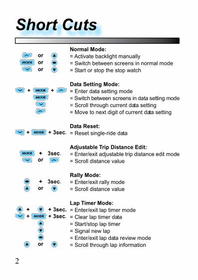
Normal Mode:= Activate backlight manually= Switch between screens in normal mode= Start or stop the stop watch
Data Setting Mode:= Enter data setting mode= Switch between screens in data setting mode= Scroll through current data setting= Move to next digit of current data setting
Data Reset:= Reset single-ride data
Adjustable Trip Distance Edit:= Enter/exit adjustable trip distance edit mode= Scroll distance value
Rally Mode:= Enter/exit rally mode= Scroll distance value
Lap Timer Mode:= Enter/exit lap timer mode= Clear lap timer data= Start/stop lap timer= Signal new lap= Enter/exit lap data review mode= Scroll through lap information
Short Cuts
2
3
Table Of Contents
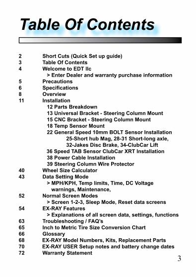
2 Short Cuts (Quick Set up guide)3 Table Of Contents4 Welcome to EDT llc > Enter Dealer and warranty purchase information5 Precautions6 Specifications8 Overview11 Installation 12 Parts Breakdown 13 Universal Bracket - Steering Column Mount 15 CNC Bracket - Steering Column Mount 18 Temp Sensor Mount 22 General Speed 10mm BOLT Sensor Installation 25-Short hub Mag, 28-31 Short-long axle, 32-Jakes Disc Brake, 34-ClubCar Lift 36 Speed TAB Sensor ClubCar XRT Installation 38 Power Cable Installation 39 Steering Column Wire Protector40 Wheel Size Calculator43 Data Setting Mode > MPH/KPH, Temp limits, Time, DC Voltage warnings, Maintenance, 52 Normal Screen Modes > Screen 1-2-3, Sleep Mode, Reset data screens54 EX-RAY Features > Explanations of all screen data, settings, functions63 Troubleshooting / FAQ’s65 Inch to Metric Tire Size Conversion Chart66 Glossary68 EX-RAY Model Numbers, Kits, Replacement Parts70 EX-RAY USER Setup notes and battery change dates72 Warranty Statement
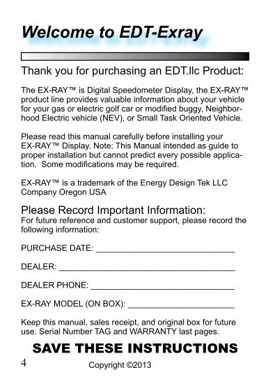
Thank you for purchasing an EDT.llc Product:
The EX-RAY™ is Digital Speedometer Display, the EX-RAY™ product line provides valuable information about your vehicle for your gas or electric golf car or modified buggy, Neighbor-hood Electric vehicle (NEV), or Small Task Oriented Vehicle.
Please read this manual carefully before installing your EX-RAY™ Display. Note: This Manual intended as guide to proper installation but cannot predict every possible applica-tion. Some modifications may be required.
EX-RAY™ is a trademark of the Energy Design Tek LLC Company Oregon USA
Please Record Important Information:For future reference and customer support, please record the following information:
PURCHASE DATE: ______________________________
DEALER: ______________________________________
DEALER PHONE: _______________________________
EX-RAY MODEL (ON BOX): _______________________
Keep this manual, sales receipt, and original box for future use. Serial Number TAG and WARRANTY last pages.
SAVE THESE INSTRUCTIONS4
Welcome to EDT-Exray
Copyright ©2013

WARNING:When using the EX-RAY™ follow basic precautions, including the following:
• Read all instructions be-fore using the EX-RAY™
• When installing the DC Motor temperature Sensor, be careful removing the bolt and not to damage the motors internal field coil. EDT llc is not responsible for damage done during this process.
• Use EX-RAY™ only for its intended purpose.
• To reduce rick or injury, do not disassemble EX-RAY™ or its accessories.
• EX-RAY™ can be used in the rain but should not be used under water.
• Do not leave the main unit in direct sunlight when not being used.
• Check magnetic sensor gap and magnet mounting periodically.
• Do not bend, twist, kink, or otherwise abuse the sensor cables. A damaged cable may produce incorrect read-ings.
• When installing EX-RAY™, turn the vehicle power off (or ignition switch off); the wires carry power from the vehicles battery.
• Avoid contact with gaso-line, de-greasers or other chemical cleaners as they may damage the EX-RAY™.
• Do not exceed 60VDC at any time as this may dam-age the EX-RAY™.
Precautions
5Copyright ©2013
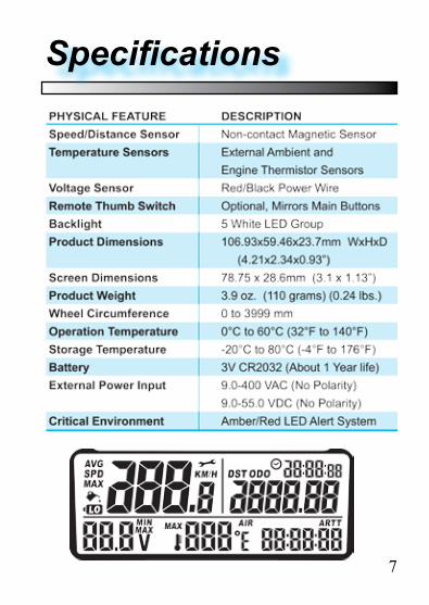
Specifications
6
7
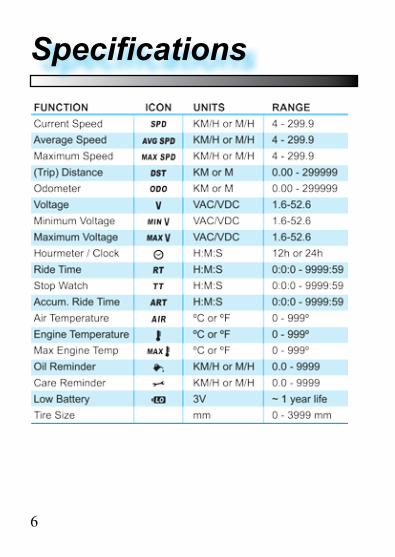
Specifications
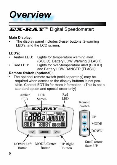
OverviewEX-RAY™ Digital Speedometer:
Main Display:• The display panel includes 3-user buttons, 2-warning
LED’s, and the LCD screen.
LED’s:• Amber LED: Lights for temperature warning alert
(SOLID), Battery LOW Warning (FLASH).• Red LED: Lights for over-temperature alert (SOLID)
and Battery LOW DANGER (FLASH).Remote Switch (optional):• The optional remote switch (sold separately) may be
required when access to the display buttons is not pos-sible. Contact EDT llc for more information. (This is not a standard option and special order only)
8
UP
MODE
DOWN
Small arrow faces UP
Remote Switch
Amber LED
Red LED
LCD Screen
DOWN Left Button
UP Right Button
MODE Center Button
Parts and Features
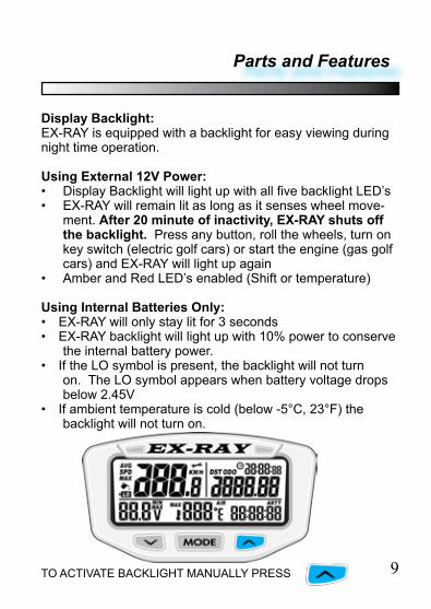
9TO ACTIVATE BACKLIGHT MANUALLY PRESS
Display Backlight:EX-RAY is equipped with a backlight for easy viewing during night time operation.
Using External 12V Power:• Display Backlight will light up with all five backlight LED’s• EX-RAY will remain lit as long as it senses wheel move-
ment. After 20 minute of inactivity, EX-RAY shuts off the backlight. Press any button, roll the wheels, turn on key switch (electric golf cars) or start the engine (gas golf cars) and EX-RAY will light up again
• Amber and Red LED’s enabled (Shift or temperature)
Using Internal Batteries Only:• EX-RAY will only stay lit for 3 seconds• EX-RAY backlight will light up with 10% power to conserve
the internal battery power.• If the LO symbol is present, the backlight will not turn
on. The LO symbol appears when battery voltage drops below 2.45V
• If ambient temperature is cold (below -5°C, 23°F) the backlight will not turn on.
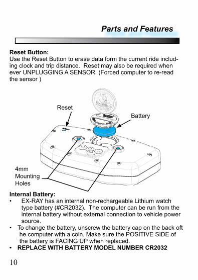
BatteryReset
4mm Mounting Holes
Reset Button:Use the Reset Button to erase data form the current ride includ-ing clock and trip distance. Reset may also be required when ever UNPLUGGING A SENSOR. (Forced computer to re-read the sensor )
Internal Battery:• EX-RAY has an internal non-rechargeable Lithium watch
type battery (#CR2032). The computer can be run from the internal battery without external connection to vehicle power source.
• To change the battery, unscrew the battery cap on the back oft he computer with a coin. Make sure the POSITIVE SIDE of the battery is FACING UP when replaced.
• REPLACE WITH BATTERY MODEL NUMBER CR2032
10
Parts and Features
Installation
11
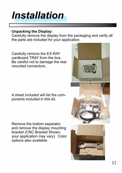
Unpacking the Display:Carefully remove the display from the packaging and verify all the parts are included for your application.
Carefully remove the EX-RAY cardboard TRAY from the box. Be careful not to damage the rear mounted connectors.
A sheet included will list the com-ponents included in this kit.
Remove the bottom separator and remove the display mounting bracket (CNC Bracket Shown, your application may vary). Color options also available.
12
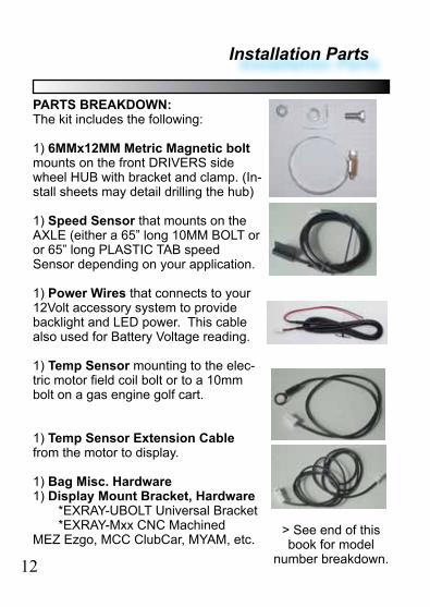
PARTS BREAKDOWN:The kit includes the following:
1) 6MMx12MM Metric Magnetic bolt mounts on the front DRIVERS side wheel HUB with bracket and clamp. (In-stall sheets may detail drilling the hub)
1) Speed Sensor that mounts on the AXLE (either a 65” long 10MM BOLT or or 65” long PLASTIC TAB speed Sensor depending on your application.
1) Power Wires that connects to your 12Volt accessory system to provide backlight and LED power. This cable also used for Battery Voltage reading.
1) Temp Sensor mounting to the elec-tric motor field coil bolt or to a 10mm bolt on a gas engine golf cart.
1) Temp Sensor Extension Cable from the motor to display.
1) Bag Misc. Hardware1) Display Mount Bracket, Hardware *EXRAY-UBOLT Universal Bracket *EXRAY-Mxx CNC MachinedMEZ Ezgo, MCC ClubCar, MYAM, etc.
Installation Parts
> See end of this book for model
number breakdown.
STEERING COLUMN MOUNTS:Most installations will be on the Golf Cart Steering column using the either the universal mount EXRAY-UBOLT, or optional CNC 6061-T6 Aluminum bracket EXRAY-MEZ. (Optional dashboard mounting will include separate installation instructions).
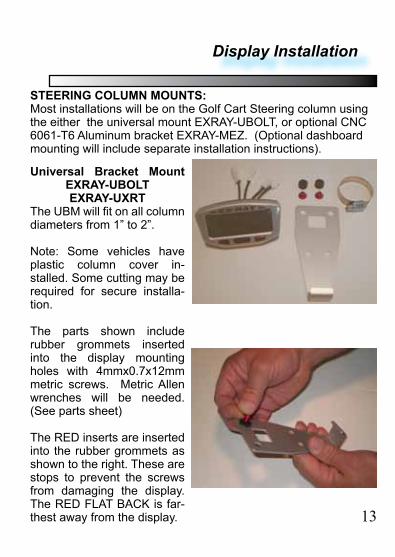
Universal Bracket Mount EXRAY-UBOLTEXRAY-UXRT
The UBM will fit on all column diameters from 1” to 2”.
Note: Some vehicles have plastic column cover in-stalled. Some cutting may be required for secure installa-tion.
The parts shown include rubber grommets inserted into the display mounting holes with 4mmx0.7x12mm metric screws. Metric Allen wrenches will be needed. (See parts sheet)
The RED inserts are inserted into the rubber grommets as shown to the right. These are stops to prevent the screws from damaging the display. The RED FLAT BACK is far-thest away from the display. 13
Display Installation
Display Installation
14
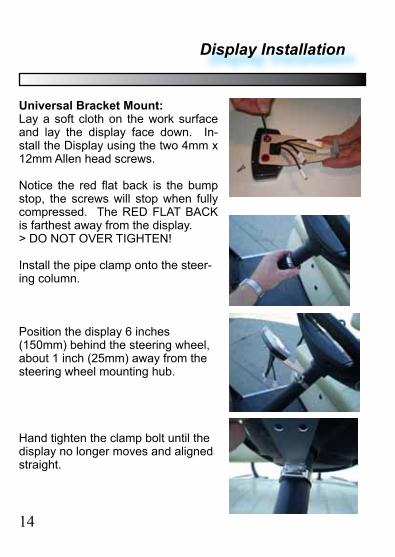
Universal Bracket Mount:Lay a soft cloth on the work surface and lay the display face down. In-stall the Display using the two 4mm x 12mm Allen head screws.
Notice the red flat back is the bump stop, the screws will stop when fully compressed. The RED FLAT BACK is farthest away from the display.> DO NOT OVER TIGHTEN!
Install the pipe clamp onto the steer-ing column.
Position the display 6 inches (150mm) behind the steering wheel, about 1 inch (25mm) away from the steering wheel mounting hub.
Hand tighten the clamp bolt until the display no longer moves and aligned straight.
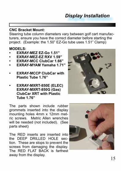
CNC Bracket Mount:Steering tube column diameters vary between golf cart manufac-turers, ensure you have the correct diameter before starting the project. (Example: the 1.50” EZ-Go tube uses 1.51” Clamp)
MODELS:• EXRAY-MEZ EZ-Go 1.51”• EXRAY-MEZ-EZ RXV 1.59”• EXRAY-MCC ClubCar 1.66”• EXRAY-MYAM Yamaha 1.71”
• EXRAY-MCCP ClubCar with Plastic Tube 1.76”
• EXRAY-MXRT-850E (ELEC)EXRAY-MXRT-850G (Gas)ClubCar XRT with Plastic Tube 1.76”
The parts shown include rubber grommets inserted into the display mounting holes 4mm x 12mm met-ric screws. Metric Allen wrenches will be needed (not included). (See parts sheet)
The RED inserts are inserted into the DEEP DRILLED HOLE sec-tion. These are stops to prevent the screws from damaging the display. The RED FLAT BACK is farthest away from the display.
15
Display Installation
Display Installation
16
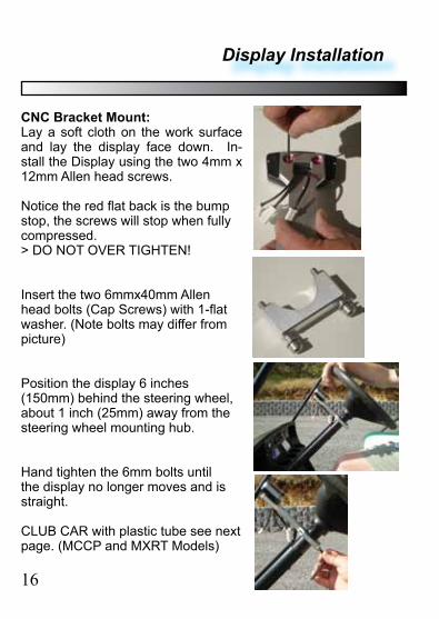
CNC Bracket Mount:Lay a soft cloth on the work surface and lay the display face down. In-stall the Display using the two 4mm x 12mm Allen head screws.
Notice the red flat back is the bump stop, the screws will stop when fully compressed. > DO NOT OVER TIGHTEN!
Insert the two 6mmx40mm Allen head bolts (Cap Screws) with 1-flat washer. (Note bolts may differ from picture)
Position the display 6 inches (150mm) behind the steering wheel, about 1 inch (25mm) away from the steering wheel mounting hub.
Hand tighten the 6mm bolts until the display no longer moves and is straight.
CLUB CAR with plastic tube see next page. (MCCP and MXRT Models)
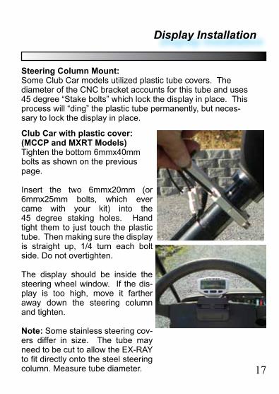
Club Car with plastic cover:(MCCP and MXRT Models)Tighten the bottom 6mmx40mm bolts as shown on the previous page.
Insert the two 6mmx20mm (or 6mmx25mm bolts, which ever came with your kit) into the 45 degree staking holes. Hand tight them to just touch the plastic tube. Then making sure the display is straight up, 1/4 turn each bolt side. Do not overtighten.
The display should be inside the steering wheel window. If the dis-play is too high, move it farther away down the steering column and tighten.
Note: Some stainless steering cov-ers differ in size. The tube may need to be cut to allow the EX-RAY to fit directly onto the steel steering column. Measure tube diameter.
Steering Column Mount:Some Club Car models utilized plastic tube covers. The diameter of the CNC bracket accounts for this tube and uses 45 degree “Stake bolts” which lock the display in place. This process will “ding” the plastic tube permanently, but neces-sary to lock the display in place.
Display Installation
17
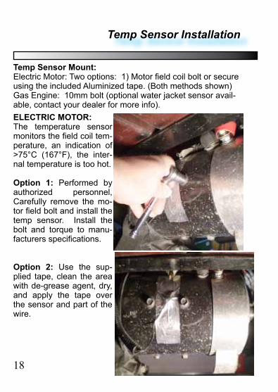
ELECTRIC MOTOR:The temperature sensor monitors the field coil tem-perature, an indication of >75°C (167°F), the inter-nal temperature is too hot.
Option 1: Performed by authorized personnel, Carefully remove the mo-tor field bolt and install the temp sensor. Install the bolt and torque to manu-facturers specifications.
Option 2: Use the sup-plied tape, clean the area with de-grease agent, dry, and apply the tape over the sensor and part of the wire.
Temp Sensor Mount:Electric Motor: Two options: 1) Motor field coil bolt or secure using the included Aluminized tape. (Both methods shown)Gas Engine: 10mm bolt (optional water jacket sensor avail-able, contact your dealer for more info).
Temp Sensor Installation
18
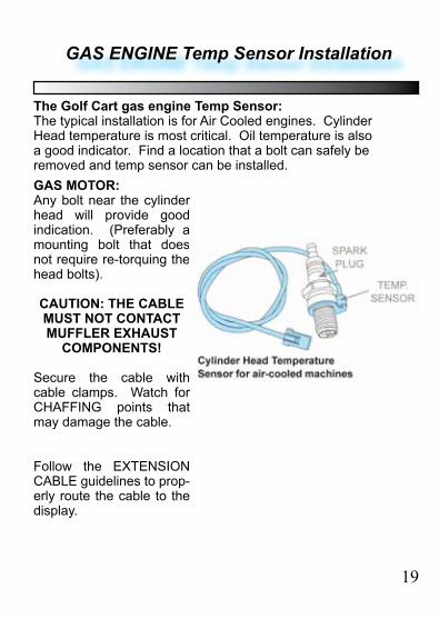
GAS ENGINE Temp Sensor Installation
GAS MOTOR:Any bolt near the cylinder head will provide good indication. (Preferably a mounting bolt that does not require re-torquing the head bolts).
CAUTION: THE CABLE MUST NOT CONTACT MUFFLER EXHAUST
COMPONENTS!
Secure the cable with cable clamps. Watch for CHAFFING points that may damage the cable.
Follow the EXTENSION CABLE guidelines to prop-erly route the cable to the display.
The Golf Cart gas engine Temp Sensor:The typical installation is for Air Cooled engines. Cylinder Head temperature is most critical. Oil temperature is also a good indicator. Find a location that a bolt can safely be removed and temp sensor can be installed.
19
Temp Sensor EXTENSION Installation
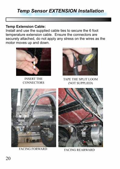
Temp Extension Cable:Install and use the supplied cable ties to secure the 6 foot temperature extension cable. Ensure the connectors are securely attached, do not apply any stress on the wires as the motor moves up and down.
20
FACING FORWARD FACING REARWARD
TAPE THE SPLIT LOOM (NOT SUPPLIED)
INSERT THE CONNECTORS
Temp Sensor EXTENSION Installation
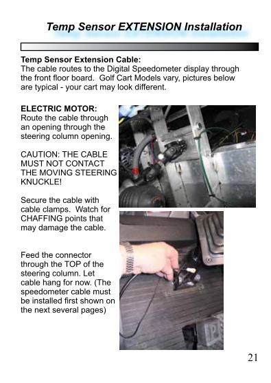
ELECTRIC MOTOR:Route the cable through an opening through the steering column opening.
CAUTION: THE CABLE MUST NOT CONTACT THE MOVING STEERING KNUCKLE!
Secure the cable with cable clamps. Watch for CHAFFING points that may damage the cable.
Feed the connector through the TOP of the steering column. Let cable hang for now. (The speedometer cable must be installed first shown on the next several pages)
Temp Sensor Extension Cable:The cable routes to the Digital Speedometer display through the front floor board. Golf Cart Models vary, pictures below are typical - your cart may look different.
21
SPEED Sensor BOLT Installation
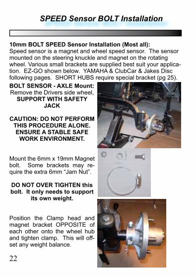
BOLT SENSOR - AXLE Mount:Remove the Drivers side wheel,
SUPPORT WITH SAFETY JACK
CAUTION: DO NOT PERFORM THIS PROCEDURE ALONE. ENSURE A STABLE SAFE
WORK ENVIRONMENT.
Mount the 6mm x 19mm Magnet bolt. Some brackets may re-quire the extra 6mm “Jam Nut”.
DO NOT OVER TIGHTEN this bolt. It only needs to support
its own weight.
Position the Clamp head and magnet bracket OPPOSITE of each other onto the wheel hub and tighten clamp. This will off-set any weight balance.
10mm BOLT SPEED Sensor Installation (Most all):Speed sensor is a magnet and wheel speed sensor. The sensor mounted on the steering knuckle and magnet on the rotating wheel. Various small brackets are supplied best suit your applica-tion. EZ-GO shown below. YAMAHA & ClubCar & Jakes Disc following pages. SHORT HUBS require special bracket (pg 25).
22
SPEED Sensor BOLT Installation
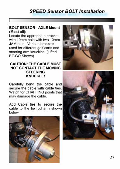
BOLT SENSOR - AXLE Mount (Most all):Locate the appropriate bracket with 10mm hole with two 10mm JAM nuts. Various brackets used for different golf carts and steering arm knuckles. (Lifted EZ-GO Shown)
CAUTION: THE CABLE MUST NOT CONTACT THE MOVING
STEERING KNUCKLE!
Carefully bend the cable and secure the cable with cable ties. Watch for CHAFFING points that may damage the cable.
Add Cable ties to secure the cable to the tie rod arm shown below.
23
SPEED Sensor BOLT Installation
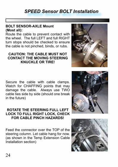
BOLT SENSOR-AXLE Mount (Most all):Route the cable to prevent contact with the wheel. The full LEFT and full RIGHT turn stops should be checked to ensure the cable is not pinched, binds, or rubs.
CAUTION: THE CABLE MUST NOT CONTACT THE MOVING STEERING
KNUCKLE OR TIRE!
Secure the cable with cable clamps. Watch for CHAFFING points that may damage the cable. Always use TWO cable ties side by side (should one break in the future)
ROTATE THE STEERING FULL LEFT LOCK TO FULL RIGHT LOCK, CHECK
FOR CABLE PINCH HAZARDS!
Feed the connector over the TOP of the steering column. Let cable hang for now. (as shown in the Temp Extension Cable Installation section)
24
SPEED Sensor BOLT Installation
BOLT SENSOR - YAMAHA G2-G22-DRIVE, EZGO SHORT HUB AXLE Mount:
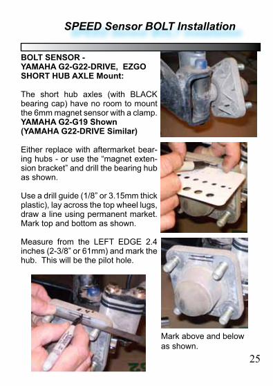
The short hub axles (with BLACK bearing cap) have no room to mount the 6mm magnet sensor with a clamp. YAMAHA G2-G19 Shown (YAMAHA G22-DRIVE Similar)
Either replace with aftermarket bear-ing hubs - or use the “magnet exten-sion bracket” and drill the bearing hub as shown.
Use a drill guide (1/8” or 3.15mm thick plastic), lay across the top wheel lugs, draw a line using permanent market. Mark top and bottom as shown.
Measure from the LEFT EDGE 2.4 inches (2-3/8” or 61mm) and mark the hub. This will be the pilot hole.
25
Mark above and below as shown.
SPEED BOLT Sensor Installation
BOLT SENSOR - YAMAHA G2-G22-DRIVE, EZGO SHORT HUB AXLE Mount:
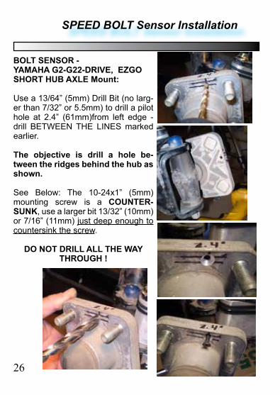
Use a 13/64” (5mm) Drill Bit (no larg-er than 7/32” or 5.5mm) to drill a pilot hole at 2.4” (61mm)from left edge - drill BETWEEN THE LINES marked earlier.
The objective is drill a hole be-tween the ridges behind the hub as shown.
See Below: The 10-24x1” (5mm) mounting screw is a COUNTER-SUNK, use a larger bit 13/32” (10mm) or 7/16” (11mm) just deep enough to countersink the screw.
DO NOT DRILL ALL THE WAY THROUGH !
26
SPEED BOLT Sensor Installation
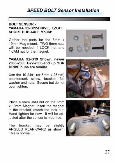
BOLT SENSOR - YAMAHA G2-G22-DRIVE, EZGO SHORT HUB AXLE Mount:
Gather the parts for the 6mm x 19mm Mag mount. TWO 6mm nuts will be needed, 1-LOCK nut and 1-JAM nut for the magnet.
YAMAHA G2-G19 Shown, newer 2003-2008 G22-2008-and up YDR DRIVE hubs are similar.
Use the 10-24x1 (or 5mm x 25mm) countersunk screw, bracket, flat washer and nuts. Secure but do not over tighten.
Place a 6mm JAM nut on the 6mm x 19mm Magnet, insert the magnet in the bracket, attach the lock nut. Hand tighten for now. It will be ad-justed after the sensor is mounted.
The bracket may be slightly ANGLED REAR-WARD as shown. This is normal.
27
28
SPEED Sensor BOLT Installation
BOLT SENSOR - CABLE INSTALL
YAMAHA G2-G19, G22, Drive, and EZGO “SHORT HUB”:
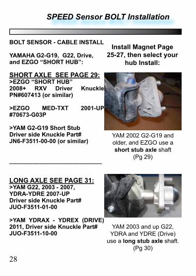
SHORT AXLE SEE PAGE 29:>EZGO “SHORT HUB” 2008+ RXV Driver Knuckle PN#607413 (or similar)
>EZGO MED-TXT 2001-UP #70673-G03P
>YAM G2-G19 Short StubDriver side Knuckle Part#JN6-F3511-00-00 (or similar)
____________________________
LONG AXLE SEE PAGE 31:>YAM G22, 2003 - 2007, YDRA-YDRE 2007-UPDriver side Knuckle Part#JUO-F3511-01-00
>YAM YDRAX - YDREX (DRIVE) 2011, Driver side Knuckle Part#JUO-F3511-10-00
YAM 2003 and up G22, YDRA and YDRE (Drive)
use a long stub axle shaft. (Pg 30)
YAM 2002 G2-G19 and older, and EZGO use a short stub axle shaft
(Pg 29)
Install Magnet Page 25-27, then select your
hub Install:
SPEED Sensor BOLT Installation
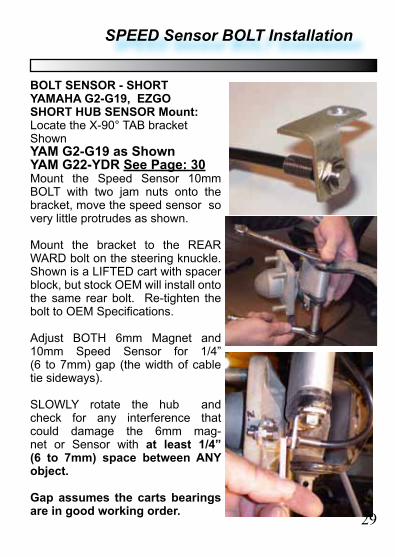
BOLT SENSOR - SHORTYAMAHA G2-G19, EZGO SHORT HUB SENSOR Mount:Locate the X-90° TAB bracket ShownYAM G2-G19 as ShownYAM G22-YDR See Page: 30Mount the Speed Sensor 10mm BOLT with two jam nuts onto the bracket, move the speed sensor so very little protrudes as shown.
Mount the bracket to the REAR WARD bolt on the steering knuckle. Shown is a LIFTED cart with spacer block, but stock OEM will install onto the same rear bolt. Re-tighten the bolt to OEM Specifications.
Adjust BOTH 6mm Magnet and 10mm Speed Sensor for 1/4” (6 to 7mm) gap (the width of cable tie sideways).
SLOWLY rotate the hub and check for any interference that could damage the 6mm mag-net or Sensor with at least 1/4” (6 to 7mm) space between ANY object.
Gap assumes the carts bearings are in good working order. 29
SPEED Sensor BOLT Installation
30
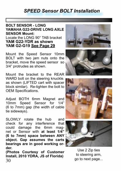
BOLT SENSOR - LONGYAMAHA G22-DRIVE LONG AXLE SENSOR Mount:Locate the LONG 90° TAB bracketYAM G22-YDR as shownYAM G2-G19 See Page 29
Mount the Speed Sensor 10mm BOLT with two jam nuts onto the bracket, move the speed sensor so 3/4” protrudes as shown.
Mount the bracket to the REAR WARD bolt on the steering knuckle. as shown (LIFTED cart with spacer block similar). Re-tighten the bolt to OEM Specifications.
Adjust BOTH 6mm Magnet and 10mm Speed Sensor for 1/4” (6 to 7mm) gap (the width of cable tie sideways).
SLOWLY rotate the hub and check for any interference that could damage the 6mm mag-net or Sensor with at least 1/4” (6 to 7mm) space between ANY object. Gap assumes the carts bearings are in good working or-der.(Photos Courtesy of Customer Install, 2010 YDRA, JS of Florida)
Use 2 Zip ties to steering arm,
go to next page...
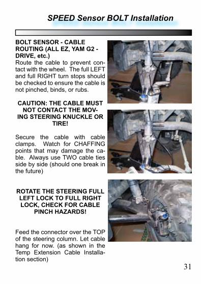
BOLT SENSOR - CABLE ROUTING (ALL EZ, YAM G2 - DRIVE, etc.)Route the cable to prevent con-tact with the wheel. The full LEFT and full RIGHT turn stops should be checked to ensure the cable is not pinched, binds, or rubs.
CAUTION: THE CABLE MUST NOT CONTACT THE MOV-
ING STEERING KNUCKLE OR TIRE!
Secure the cable with cable clamps. Watch for CHAFFING points that may damage the ca-ble. Always use TWO cable ties side by side (should one break in the future)
ROTATE THE STEERING FULL LEFT LOCK TO FULL RIGHT LOCK, CHECK FOR CABLE
PINCH HAZARDS!
Feed the connector over the TOP of the steering column. Let cable hang for now. (as shown in the Temp Extension Cable Installa-tion section)
31
SPEED Sensor BOLT Installation
SPEED Sensor BOLT Installation
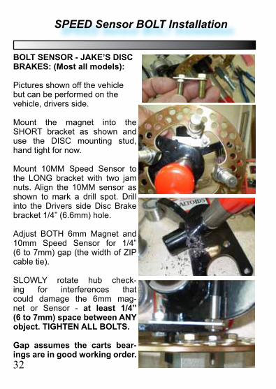
BOLT SENSOR - JAKE’S DISC BRAKES: (Most all models):
Pictures shown off the vehicle but can be performed on the vehicle, drivers side.
Mount the magnet into the SHORT bracket as shown and use the DISC mounting stud, hand tight for now.
Mount 10MM Speed Sensor to the LONG bracket with two jam nuts. Align the 10MM sensor as shown to mark a drill spot. Drill into the Drivers side Disc Brake bracket 1/4” (6.6mm) hole.
Adjust BOTH 6mm Magnet and 10mm Speed Sensor for 1/4” (6 to 7mm) gap (the width of ZIP cable tie).
SLOWLY rotate hub check-ing for interferences that could damage the 6mm mag-net or Sensor - at least 1/4” (6 to 7mm) space between ANY object. TIGHTEN ALL BOLTS.
Gap assumes the carts bear-ings are in good working order.32
33
SPEED Sensor BOLT Installation
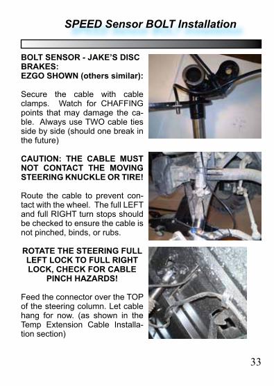
BOLT SENSOR - JAKE’S DISC BRAKES:EZGO SHOWN (others similar):
Secure the cable with cable clamps. Watch for CHAFFING points that may damage the ca-ble. Always use TWO cable ties side by side (should one break in the future)
CAUTION: THE CABLE MUST NOT CONTACT THE MOVING STEERING KNUCKLE OR TIRE!
Route the cable to prevent con-tact with the wheel. The full LEFT and full RIGHT turn stops should be checked to ensure the cable is not pinched, binds, or rubs.
ROTATE THE STEERING FULL LEFT LOCK TO FULL RIGHT LOCK, CHECK FOR CABLE
PINCH HAZARDS!
Feed the connector over the TOP of the steering column. Let cable hang for now. (as shown in the Temp Extension Cable Installa-tion section)
SPEED Sensor BOLT Installation
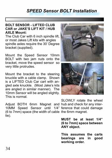
BOLT SENSOR - LIFTED CLUB CAR or JAKE’S LIFT KIT / HUB AXLE Mount:The Club Car with 6 inch spindle lift, or most Jakes Lift kits with angles spindle axles require the 30’ Degree bracket (supplied).
Mount the Speed Sensor 10mm BOLT with two jam nuts onto the bracket, move the speed sensor so very little protrudes.
Mount the bracket to the steering knuckle with a cable clamp. Shown is a LIFTED Club Car cart with an-gled axle knuckle. (Most Jake’s kits are angled in similar manner). The 10mm Sensor will be angled slightly. This is normal.
Adjust BOTH 6mm Magnet and 10MM Speed Sensor until 1/4” (6 to 7mm) space (the width of cable tie).
SLOWLY rotate the wheel hub and check for any inter-ference that could damage the 6mm magnet.
MUST be at least 1/4” (6 to 7mm) space between ANY object.
This assumes the carts bearings are in good working order.
34

BOLT SENSOR - LIFTED CLUB CAR or JAKE’S LIFT KIT / HUB AXLE Mount:
Attach cable ties to the steering arm. Rotate the steering wheel FULL LEFT and FULL RIGHT and check for binding.
Route the cable as described earlier.
CAUTION: THE CABLE MUST NOT CONTACT THE
MOVING STEERING KNUCKLE OR TIRE!
Secure the cable with cable clamps. Watch for CHAFFING points that may damage the cable. Always use TWO cable ties side by side (should one break in the future).
Mount the wheel and recheck for rubbing or any damage that may occur to the cable.
Feed the connector through the TOP of the steering column. Let cable hang for now. (as shown in the Temp Extension Cable Installa-tion section)
SPEED Sensor BOLT Installation
35
XRT-850E SPEED Sensor TAB Installation
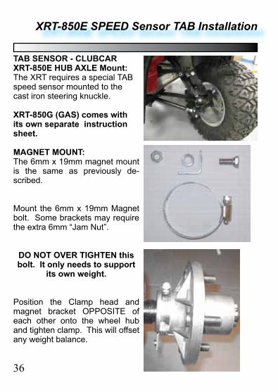
TAB SENSOR - CLUBCAR XRT-850E HUB AXLE Mount:The XRT requires a special TAB speed sensor mounted to the cast iron steering knuckle.
XRT-850G (GAS) comes with its own separate instruction sheet.
MAGNET MOUNT:The 6mm x 19mm magnet mount is the same as previously de-scribed.
Mount the 6mm x 19mm Magnet bolt. Some brackets may require the extra 6mm “Jam Nut”.
DO NOT OVER TIGHTEN this bolt. It only needs to support
its own weight.
Position the Clamp head and magnet bracket OPPOSITE of each other onto the wheel hub and tighten clamp. This will offset any weight balance.
36
XRT-850E SPEED Sensor TAB Installation
37
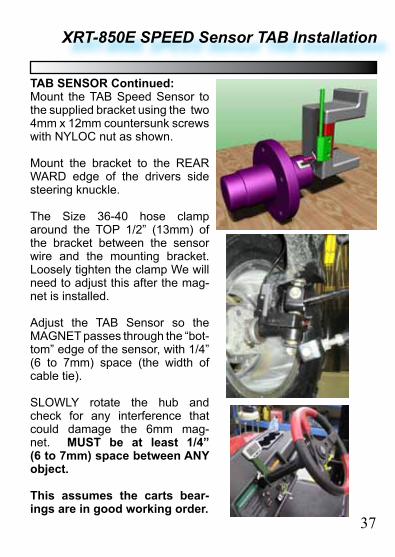
TAB SENSOR Continued:Mount the TAB Speed Sensor to the supplied bracket using the two 4mm x 12mm countersunk screws with NYLOC nut as shown.
Mount the bracket to the REAR WARD edge of the drivers side steering knuckle.
The Size 36-40 hose clamp around the TOP 1/2” (13mm) of the bracket between the sensor wire and the mounting bracket. Loosely tighten the clamp We will need to adjust this after the mag-net is installed.
Adjust the TAB Sensor so the MAGNET passes through the “bot-tom” edge of the sensor, with 1/4” (6 to 7mm) space (the width of cable tie).
SLOWLY rotate the hub and check for any interference that could damage the 6mm mag-net. MUST be at least 1/4” (6 to 7mm) space between ANY object.
This assumes the carts bear-ings are in good working order.
Power Wire (Optional) Installation
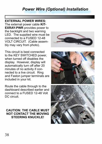
EXTERNAL POWER WIRES:The external power cable KIT-EXRAY-PWR provides power to the backlight and two warning LED. The supplied wire must be connected to a FUSED 12-48 VOLT CIRCUIT. (Cable assem-bly may vary from photo).
This circuit is best connected to the KEY SWITCHED power, when turned off disables the display. However, display will automatically turn off after 20 minutes of no activity if con-nected to a live circuit. Ring and Faston jumper terminals are included in your kit.
Route the cable through to the dashboard described earlier and connect to a FUSED 12-48 Volt DC circuit.
CAUTION: THE CABLE MUST NOT CONTACT THE MOVING
STEERING KNUCKLE!
38

Wire Harness Protection:The wires are routed along the TOP of the steering column. A optional protection tube cov-ers the wires and offers a clean installation look. EDT llc MODEL: HDW800-006-CPT
Carefully attached all the con-nectors. Make sure the fragile wires are NOT STRESSED. Leave a little slack. ** Use cable ties to secure the wires to the steering column.
Snap the optional column protec-tor in place, careful not to pinch any wires. (Display removed for clarity in this picture.
Installation Complete. (Optional CNC machined bracket Model EXRAY-MEZ shown)
Proceed to the SETUP PROCE-DURE.
Wiring Column Protector Installation
39
Tire Wheel Size Calculation
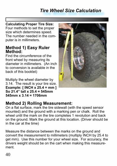
Calculating Proper Tire Size:Four methods to set the proper size which determines speed. The number needed in the com-puter is in millimeters.
Method 1) Easy Ruler Method:Find the circumference of the front wheel by measuring its diameter in millimeters. (An inch to conversion is available in the back of this booklet)
Multiply the wheel diameter by 3.14. The result is your tire size.Example: [ INCH x 25.4 = mm ]So 21.4” tall x 25.4 = 545mm545mm x 3.14 = 1706mm
Method 2) Rolling Measurement:On a flat surface, mark the tire sidewall (with the speed sensor mounted) and the ground with a marking pen or chalk. Roll the wheel until the mark on the tire completes 1 revolution and back on the ground. Mark the ground at this location. (Driver should be in the car at the time)
Measure the distance between the marks on the ground and convert the measurement to millimeters (multiply INCH by 25.4 to get mm). Use this number for your wheel size. For accuracy, the drivers weight should be on the cart when making this measure-ment.
40
Tire Wheel Size Calculation
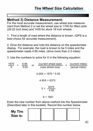
Method 3) Distance Measurement:For the most accurate measurement, use wheel size measure-ment from Method 2 or set the wheel size to 1700 for lifted carts (20-22 inch tires) and 1435 for stock 18 inch wheels.
1. Find a length of road where the distance is known. (GPS is a best choice for accurate measurement).
2. Drive the distance and note the distance on the speedometer display. For example, the road is known to be 5 miles and the speedometer reads 4.95 miles. (drive more than 2-3 miles)
3. Use the numbers to solve for X in the following equation:
Enter the new number from above method into the Speedometer (Described later in this booklet) Record this number below.
My Tire Size is:
41
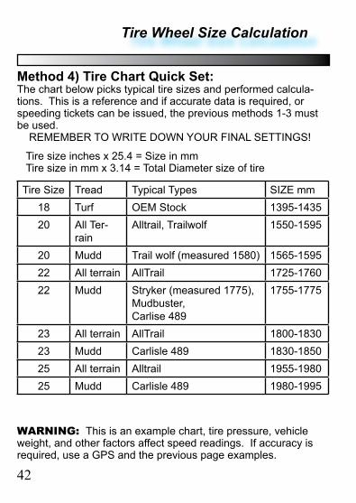
Tire size inches x 25.4 = Size in mm Tire size in mm x 3.14 = Total Diameter size of tire
Tire Size Tread Typical Types SIZE mm18 Turf OEM Stock 1395-143520 All Ter-
rainAlltrail, Trailwolf 1550-1595
20 Mudd Trail wolf (measured 1580) 1565-159522 All terrain AllTrail 1725-176022 Mudd Stryker (measured 1775),
Mudbuster, Carlise 489
1755-1775
23 All terrain AllTrail 1800-183023 Mudd Carlisle 489 1830-185025 All terrain Alltrail 1955-198025 Mudd Carlisle 489 1980-1995
WARNING: This is an example chart, tire pressure, vehicle weight, and other factors affect speed readings. If accuracy is required, use a GPS and the previous page examples.
42
Tire Wheel Size Calculation
Method 4) Tire Chart Quick Set:The chart below picks typical tire sizes and performed calcula-tions. This is a reference and if accurate data is required, or speeding tickets can be issued, the previous methods 1-3 must be used. REMEMBER TO WRITE DOWN YOUR FINAL SETTINGS!
DATA SETTING MODE
43
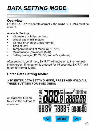
Overview:For the EX-RAY to operate correctly, the DATA SETTING must be correct.
Available Settings:• Kilometers or Miles per Hour• Wheel size in millimeters• 12 hour or 24 hour Clock Format• Time of Day• Temperature unit of Measure, °F or °C• Maintenance Reminders (M/K)• Battery Voltage (12, 24, 36, and 48V systems)
After setting is confirmed, EX-RAY will move on to the next set-ting in order. If no button is pressed for 15 seconds, EX-RAY will return to Normal Mode.
Enter Data Setting Mode:
> TO ENTER DATA SETTING MODE, PRESS AND HOLD ALL THREE BUTTONS FOR 3-SECONDS:
All digits will turn on. Release the buttons to continue.
Data Setting
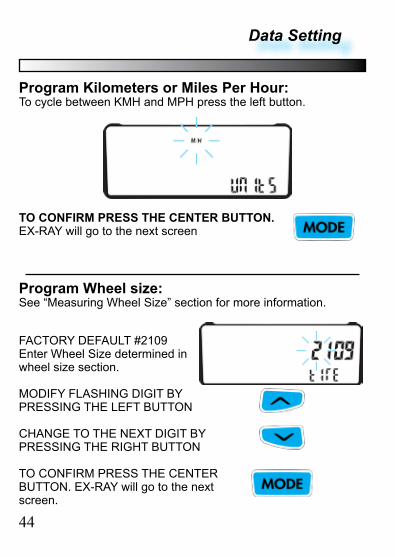
Program Kilometers or Miles Per Hour:To cycle between KMH and MPH press the left button.
TO CONFIRM PRESS THE CENTER BUTTON. EX-RAY will go to the next screen
44
Program Wheel size:See “Measuring Wheel Size” section for more information.
FACTORY DEFAULT #2109Enter Wheel Size determined in wheel size section.
MODIFY FLASHING DIGIT BY PRESSING THE LEFT BUTTON
CHANGE TO THE NEXT DIGIT BY PRESSING THE RIGHT BUTTON
TO CONFIRM PRESS THE CENTER BUTTON. EX-RAY will go to the next screen.

Data Setting
Program 12 or 24 Hour Clock:EX-RAY factory default is 12 hour format..
TO CYCLE BETWEEN 12 AND 24 HOURS, PRESS THE LEFT BUTTON
TO CONFIRM PRESS THE CENTER BUTTON. EX-RAY will go to the next screen
Program Time of Day:
MODIFY FLASHING DIGIT BY PRESSING THE LEFT BUTTON
CHANGE TO THE NEXT DIGIT BY PRESSING THE RIGHT BUTTON
TO CONFIRM PRESS THE CEN-TER BUTTON. EX-RAY will go to the next screen.
45
Data Setting
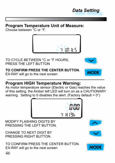
Program Temperature Unit of Measure:Choose between °C or °F.
TO CYCLE BETWEEN °C or °F HOURS, PRESS THE LEFT BUTTON
TO CONFIRM PRESS THE CENTER BUTTON. EX-RAY will go to the next screen
Program HIGH Temperature Warning:As motor temperature sensor (Electric or Gas) reaches the value of this setting, the Amber left LED will turn on as a CAUTIONARY warning. Setting to 0 disables the alert. (Factory default = 0°)
MODIFY FLASHING DIGITS BY PRESSING THE LEFT BUTTON.
TO CONFIRM PRESS THE CENTER BUTTON. EX-RAY will go to the next screen46
CHANGE TO NEXT DIGIT BY PRESSING RIGHT BUTTON.
Data Setting
47
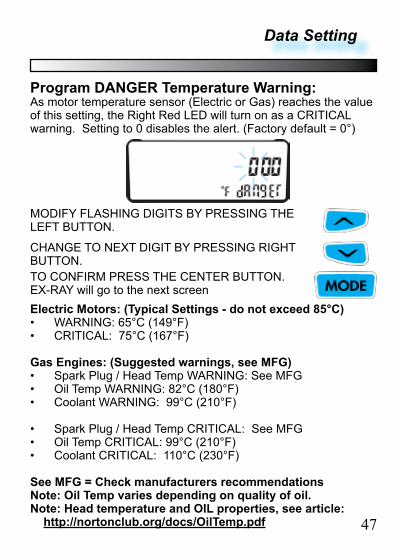
Program DANGER Temperature Warning:As motor temperature sensor (Electric or Gas) reaches the value of this setting, the Right Red LED will turn on as a CRITICAL warning. Setting to 0 disables the alert. (Factory default = 0°)
MODIFY FLASHING DIGITS BY PRESSING THE LEFT BUTTON.
TO CONFIRM PRESS THE CENTER BUTTON. EX-RAY will go to the next screen
CHANGE TO NEXT DIGIT BY PRESSING RIGHT BUTTON.
Electric Motors: (Typical Settings - do not exceed 85°C)• WARNING: 65°C (149°F)• CRITICAL: 75°C (167°F)
Gas Engines: (Suggested warnings, see MFG)• Spark Plug / Head Temp WARNING: See MFG• Oil Temp WARNING: 82°C (180°F)• Coolant WARNING: 99°C (210°F)
• Spark Plug / Head Temp CRITICAL: See MFG• Oil Temp CRITICAL: 99°C (210°F)• Coolant CRITICAL: 110°C (230°F)
See MFG = Check manufacturers recommendationsNote: Oil Temp varies depending on quality of oil.Note: Head temperature and OIL properties, see article: http://nortonclub.org/docs/OilTemp.pdf
48
Data Setting
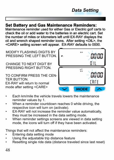
Set Battery and Gas Maintenance Reminders:Maintenance reminder used for either Gas or Electric golf carts to check the oil or add water to the batteries in an electric cart. Set the number of miles or kilometers left until EX-RAY displays the oil and wrench shaped reminder icons. After setting <OIL>, the <CARE> setting screen will appear. EX-RAY defaults to 0000.
MODIFY FLASHING DIGITS BY PRESSING THE LEFT BUTTON.
TO CONFIRM PRESS THE CEN-TER BUTTON. EX-RAY will return to normal mode after setting <CARE>
CHANGE TO NEXT DIGIT BY PRESSING RIGHT BUTTON.
Set Battery and Gas Maintenance Reminders:Maintenance reminder used for either Gas or Electric golf carts to check the oil or add water to the batteries in an electric cart. Set the number of miles or kilometers left until EX-RAY displays the oil and wrench shaped reminder icons. After setting <OIL>, the <CARE> setting screen will appear. EX-RAY defaults to 0000.
• Each km/mile the vehicle travels lowers the maintenance reminder values by 1.
• When a reminder countdown reaches 0 while driving, the respective icon will turn on (activate).
• EX-RAY will not increase the reminder value automatically, they must be increased in the data setting mode.
• When reminder settings screens are viewed in data setting mode, the icons will turn off if they have been activated.
Things that will not affect the maintenance reminders:• Entering data setting mode• Using the adjustable trip distance feature• Resetting single ride data (distance traveled since last reset)
Data Setting
49
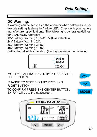
DC Warning:A warning can be set to alert the operator when batteries are be-low this setting flashing the Yellow LED. Check with your battery manufacturer specifications. The following is general guidelines for LEAD ACID batteries:12V Battery: Warning 10.5-11.0V (Gas vehicles)24V Battery: Warning 21V36V Battery: Warning 31.5V48V Battery: Warning 42.0VSetting to 0 disables the alert. (Factory default = 0 no warning)
MODIFY FLASHING DIGITS BY PRESSING THE LEFT BUTTON.
TO CONFIRM PRESS THE CENTER BUTTON. EX-RAY will go to the next screen.
CHANGE TO NEXT DIGIT BY PRESSING RIGHT BUTTON.
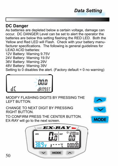
DC DangerAs batteries are depleted below a certain voltage, damage can occur. DC DANGER Level can be set to alert the operator the batteries are below this setting flashing the RED LED. Both the Yellow and Red LED will Flash. Check with your battery manu-facturer specifications. The following is general guidelines for LEAD ACID batteries:12V Battery: Warning 9.75V24V Battery: Warning 19.5V36V Battery: Warning 29V48V Battery: Warning 39VSetting to 0 disables the alert. (Factory default = 0 no warning)
50
Data Setting
MODIFY FLASHING DIGITS BY PRESSING THE LEFT BUTTON.
TO CONFIRM PRESS THE CENTER BUTTON. EX-RAY will go to the next screen.
CHANGE TO NEXT DIGIT BY PRESSING RIGHT BUTTON.
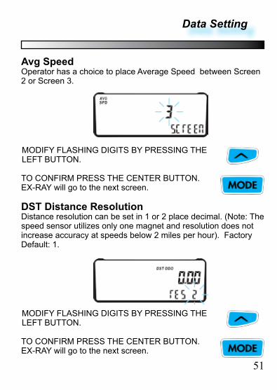
DST Distance ResolutionDistance resolution can be set in 1 or 2 place decimal. (Note: The speed sensor utilizes only one magnet and resolution does not increase accuracy at speeds below 2 miles per hour). Factory Default: 1.
Data Setting
MODIFY FLASHING DIGITS BY PRESSING THE LEFT BUTTON.
TO CONFIRM PRESS THE CENTER BUTTON. EX-RAY will go to the next screen.
51
Avg SpeedOperator has a choice to place Average Speed between Screen 2 or Screen 3.
MODIFY FLASHING DIGITS BY PRESSING THE LEFT BUTTON.
TO CONFIRM PRESS THE CENTER BUTTON. EX-RAY will go to the next screen.

NORMAL MODE SCREENS
Switch between 3 Normal Mode Screens:All of the information the EX-RAY provides is on one of these 3 screens.
When driving, the user has the choice of staying on screen 1 or screen 2. Screen 3 will default back to screen 1 after 5 seconds.
TO SWITCH BETWEEN SCREENS, PRESS THE CENTER BUTTON
SCREEN 1:Screen 1 displays:• Speed (SPD)• Distance (DST)• Battery Voltage• Ride Time (RT)• Time of Day• Engine Tempera-
ture (above 100°F)
52
53
Normal Screen Modes
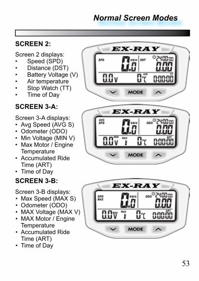
SCREEN 2:Screen 2 displays:• Speed (SPD)• Distance (DST)• Battery Voltage (V)• Air temperature• Stop Watch (TT)• Time of Day
SCREEN 3-A:Screen 3-A displays:• Avg Speed (AVG S)• Odometer (ODO)• Min Voltage (MIN V)• Max Motor / Engine
Temperature• Accumulated Ride
Time (ART)• Time of DaySCREEN 3-B:Screen 3-B displays:• Max Speed (MAX S)• Odometer (ODO)• MAX Voltage (MAX V)• MAX Motor / Engine
Temperature• Accumulated Ride
Time (ART)• Time of Day
EX-RAY FEATURES
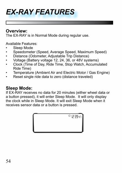
Overview:The EX-RAY is in Normal Mode during regular use.
Available Features:• Sleep Mode• Speedometer (Speed, Average Speed, Maximum Speed)• Distance (Odometer, Adjustable Trip Distance)• Voltage (Battery voltage 12, 24, 36, or 48V systems)• Clock (Time of Day, Ride Time, Stop Watch, Accumulated
Ride Time)• Temperature (Ambient Air and Electric Motor / Gas Engine)• Reset single ride data to zero (distance traveled)
Sleep Mode:If EX-RAY receives no data for 20 minutes (either wheel data or a button pressed), it will enter Sleep Mode. It will only display the clock while in Sleep Mode. It will exit Sleep Mode when it receives sensor data or a button is pressed.
54
55
EX-RAY Features
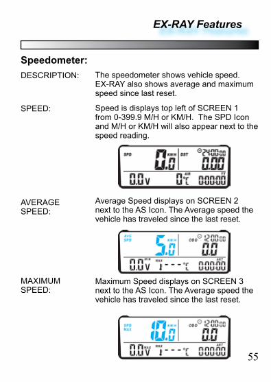
Speedometer:The speedometer shows vehicle speed. EX-RAY also shows average and maximum speed since last reset.
DESCRIPTION:
SPEED:
AVERAGE SPEED:
MAXIMUM SPEED:
Speed is displays top left of SCREEN 1 from 0-399.9 M/H or KM/H. The SPD Icon and M/H or KM/H will also appear next to the speed reading.
Average Speed displays on SCREEN 2 next to the AS Icon. The Average speed the vehicle has traveled since the last reset.
Maximum Speed displays on SCREEN 3 next to the AS Icon. The Average speed the vehicle has traveled since the last reset.
EX-RAY Features
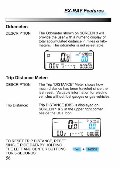
Odometer:The Odometer shown on SCREEN 3 will provide the user with a numeric display of total accumulated distance in miles or kilo-meters. The odometer is not re-set able.
DESCRIPTION:
Trip Distance Meter:The Trip “DISTANCE” Meter shows how much distance has been traveled since the last reset. Valuable information for electric vehicles without fuel gauges or gas vehicles.
DESCRIPTION:
Trip DISTANCE (DIS) is displayed on SCREEN 1 & 2 in the upper right corner beside the DST Icon.
Trip Distance:
TO RESET TRIP DISTANCE, RESET SINGLE RIDE DATA BY HOLDING THE LEFT AND CENTER BUTTONS FOR 3-SECONDS56
EX-RAY Features
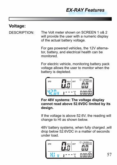
Voltage:The Volt meter shown on SCREEN 1 o& 2 will provide the user with a numeric display of the actual battery voltage.
For gas powered vehicles, the 12V alterna-tor, battery, and electrical health can be monitored.
For electric vehicle, monitoring battery pack voltage allows the user to monitor when the battery is depleted.
DESCRIPTION:
For 48V systems: The voltage display cannot read above 52.6VDC limited by its design.
If the voltage is above 52.6V, the reading will change to HI as shown below.
48V battery systems, when fully charged ,will drop below 52.6VDC in a matter of seconds under load.
57
EX-RAY Features
58
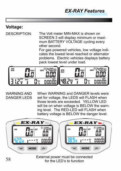
Voltage:The Volt meter MIN-MAX is shown on SCREEN 3 will display minimum or maxi-mum BATTERY VOLTAGE cycling every other second. For gas powered vehicles, low voltage indi-cates the lowest level reached or alternator problems. Electric vehicles displays battery pack lowest level under load.
DESCRIPTION:
WARNING AND DANGER LEDS
When WARNING and DANGER levels were set for voltage, the LEDS will FLASH when those levels are exceeded. YELLOW LED will be on when voltage is BELOW the warn-ing level. The RED-LED will FLASH when battery voltage is BELOW the danger level.
External power must be connected for the LED’s to function
EX-RAY Features
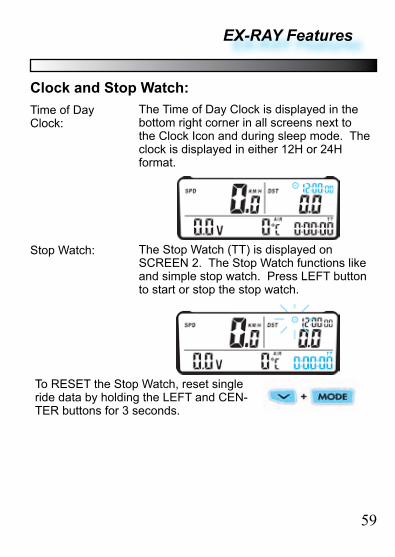
Clock and Stop Watch:The Time of Day Clock is displayed in the bottom right corner in all screens next to the Clock Icon and during sleep mode. The clock is displayed in either 12H or 24H format.
Time of Day Clock:
The Stop Watch (TT) is displayed on SCREEN 2. The Stop Watch functions like and simple stop watch. Press LEFT button to start or stop the stop watch.
Stop Watch:
To RESET the Stop Watch, reset single ride data by holding the LEFT and CEN-TER buttons for 3 seconds.
59
EX-RAY Features
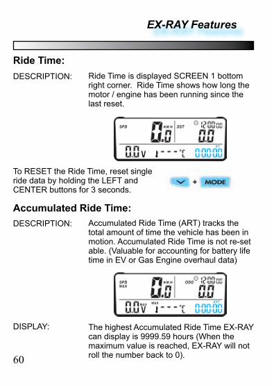
Ride Time:Ride Time is displayed SCREEN 1 bottom right corner. Ride Time shows how long the motor / engine has been running since the last reset.
DESCRIPTION:
Accumulated Ride Time (ART) tracks the total amount of time the vehicle has been in motion. Accumulated Ride Time is not re-set able. (Valuable for accounting for battery life time in EV or Gas Engine overhaul data)
DESCRIPTION:
To RESET the Ride Time, reset single ride data by holding the LEFT and CENTER buttons for 3 seconds.
60
Accumulated Ride Time:
The highest Accumulated Ride Time EX-RAY can display is 9999.59 hours (When the maximum value is reached, EX-RAY will not roll the number back to 0).
DISPLAY:
EX-RAY Features
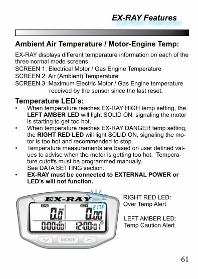
Ambient Air Temperature / Motor-Engine Temp:EX-RAY displays different temperature information on each of the three normal mode screens.SCREEN 1: Electrical Motor / Gas Engine TemperatureSCREEN 2: Air (Ambient) TemperatureSCREEN 3: Maximum Electric Motor / Gas Engine temperature received by the sensor since the last reset.
Temperature LED’s:• When temperature reaches EX-RAY HIGH temp setting, the
LEFT AMBER LED will light SOLID ON, signaling the motor is starting to get too hot.
• When temperature reaches EX-RAY DANGER temp setting, the RIGHT RED LED will light SOLID ON, signaling the mo-tor is too hot and recommended to stop.
• Temperature measurements are based on user defined val-ues to advise when the motor is getting too hot. Tempera-ture cutoffs must be programmed manually. See DATA SETTING section.
• EX-RAY must be connected to EXTERNAL POWER or LED’s will not function.
61
RIGHT RED LED: Over Temp Alert
LEFT AMBER LED: Temp Caution Alert
EX-RAY Features
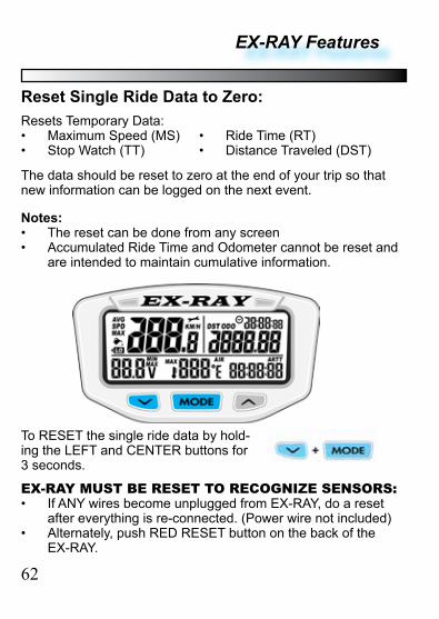
Reset Single Ride Data to Zero:
The data should be reset to zero at the end of your trip so that new information can be logged on the next event.
Resets Temporary Data:• Maximum Speed (MS)• Stop Watch (TT)
• Ride Time (RT)• Distance Traveled (DST)
Notes:• The reset can be done from any screen• Accumulated Ride Time and Odometer cannot be reset and
are intended to maintain cumulative information.
To RESET the single ride data by hold-ing the LEFT and CENTER buttons for 3 seconds.
62
EX-RAY MUST BE RESET TO RECOGNIZE SENSORS:• If ANY wires become unplugged from EX-RAY, do a reset
after everything is re-connected. (Power wire not included)• Alternately, push RED RESET button on the back of the
EX-RAY.
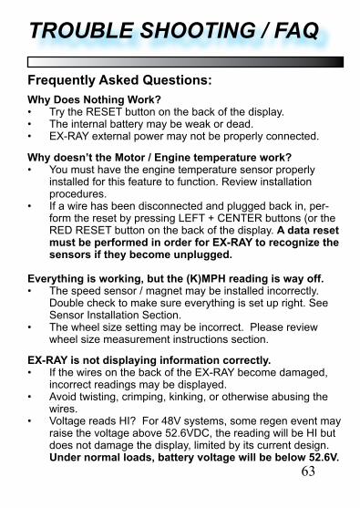
Frequently Asked Questions:Why Does Nothing Work?• Try the RESET button on the back of the display.• The internal battery may be weak or dead. • EX-RAY external power may not be properly connected.
63
TROUBLE SHOOTING / FAQ
Why doesn’t the Motor / Engine temperature work?• You must have the engine temperature sensor properly
installed for this feature to function. Review installation procedures.
• If a wire has been disconnected and plugged back in, per-form the reset by pressing LEFT + CENTER buttons (or the RED RESET button on the back of the display. A data reset must be performed in order for EX-RAY to recognize the sensors if they become unplugged.
Everything is working, but the (K)MPH reading is way off.• The speed sensor / magnet may be installed incorrectly.
Double check to make sure everything is set up right. See Sensor Installation Section.
• The wheel size setting may be incorrect. Please review wheel size measurement instructions section.
EX-RAY is not displaying information correctly.• If the wires on the back of the EX-RAY become damaged,
incorrect readings may be displayed.• Avoid twisting, crimping, kinking, or otherwise abusing the
wires.• Voltage reads HI? For 48V systems, some regen event may
raise the voltage above 52.6VDC, the reading will be HI but does not damage the display, limited by its current design. Under normal loads, battery voltage will be below 52.6V.
Trouble Shooting / FAQ
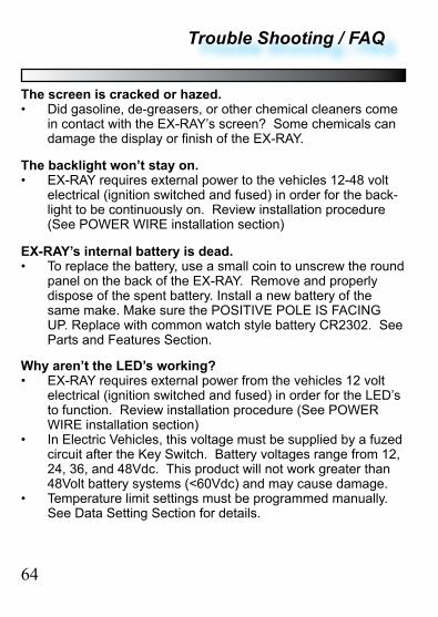
The screen is cracked or hazed.• Did gasoline, de-greasers, or other chemical cleaners come
in contact with the EX-RAY’s screen? Some chemicals can damage the display or finish of the EX-RAY.
The backlight won’t stay on.• EX-RAY requires external power to the vehicles 12-48 volt
electrical (ignition switched and fused) in order for the back-light to be continuously on. Review installation procedure (See POWER WIRE installation section)
EX-RAY’s internal battery is dead.• To replace the battery, use a small coin to unscrew the round
panel on the back of the EX-RAY. Remove and properly dispose of the spent battery. Install a new battery of the same make. Make sure the POSITIVE POLE IS FACING UP. Replace with common watch style battery CR2302. See Parts and Features Section.
Why aren’t the LED’s working?• EX-RAY requires external power from the vehicles 12 volt
electrical (ignition switched and fused) in order for the LED’s to function. Review installation procedure (See POWER WIRE installation section)
• In Electric Vehicles, this voltage must be supplied by a fuzed circuit after the Key Switch. Battery voltages range from 12, 24, 36, and 48Vdc. This product will not work greater than 48Volt battery systems (<60Vdc) and may cause damage.
• Temperature limit settings must be programmed manually. See Data Setting Section for details.
64
Inch to Metric Tire Size:
65
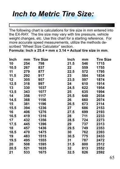
Inch mm Tire Size Inch mm Tire Size 10 254 798 21.5 546 171510.5 267 837 22 559 175511 279 877 22.5 572 179511.5 292 917 23 584 183412 305 957 23.5 597 187412.5 318 997 24 610 191413 330 1037 24.5 622 195413.5 343 1077 25 635 199414 356 1117 25.5 648 203414.5 368 1156 26 660 207415 381 1196 26.5 673 211415.5 394 1236 27 686 215316 406 1276 27.5 699 219316.5 419 1316 28 711 223317 432 1356 28.5 724 227317.5 445 1396 29 737 231318 457 1436 29.5 749 235318.5 470 1475 30 762 239319 483 1515 30.5 775 243319.5 495 1555 31 787 247220 508 1595 31.5 800 251220.5 521 1635 32 813 255221 533 1675 32.5 826 2592
The following chart is calculations for tire size in mm entered into the EX-RAY. The tire size may vary with tire pressure, vehicle weight changes, etc. Use this chart for a starting reference. For more accurate speed measurements, utilize the methods de-scribed “Wheel Size Calculator” section. Formula: Inch x 25.4 = mm x 3.14 = Actual tire size in mm.
GLOSSARY:
ACCUMULATED RIDE TIME (ART): The long term amount of time spent driving (all ride times added together). Cannot be reset.
ADJUSTABLE DISTANCE EDIT (ADST): Edit the distance trav-eled since the last trip data reset. For electric powered vehicles this can be very important data. For Gas powered golf carts without fuel gases, this can provide a known distance before refueling is required.
AVERAGE SPEED (AS): The Median (average) speed the ve-hicle has been traveling since the last trip data reset.
BACKLIGHT: The light brightens the LCD display for night time driving. Automatically comes on when power is applied to POWER input and speed sensor data is received.
BATTERY VOLTAGE: The LCD displays voltage is based oninput to the external power cable. 12, 24, 36, and 48Volt dc battery systems. Do not exceed 60VDC at any time.
DATA SETTING MODE: The place to set EX-RAY’s settings. Includes distance units, wheel size, clock format, time, tempera-ture units, high temp setting, over temp setting, and oil/battery maintenance reminders.
DISTANCE (DST): The amount of distance covered since the last reset.
HIGH/OVER TEMP INDICATORS: The LED indicators will turn on when the electric motor or gas engine gets to hot or danger-ously hot.
66
67
GLOSSARY:
MAINTENANCE REMINDERS ( ): User programmable countdown in miles or kilometers for oil, care, or battery mainte-nance in electric vehicles.
MAXIMUM SPEED (MS): Highest speed achieved since the last reset.
NORMAL MODE: EX-RAY’s standard mode of operation.
ODOMETER (ODO): The total accumulated distance EX-RAY has traveled. The odometer is permanent and cannot be reset.
RIDE TIME (RT): Shows how long the electric motor or gas engine has been running since last reset.
SENSORS: The speed sensor works with the magnet to provide EX-RAY wheel data. A second temperature sensor provides criti-cal motor temperature information to the driver.
SLEEP MODE: If EX-RAY does not receive any sensory infor-mation, it will go into sleep mode and only display to the clock.
SPEED (SPD): The current speed the vehicle is traveling.
STOP WATCH (TT): A short term regular stop watch.
WHEEL SIZE: Very important. Used to determine speed and distance, Refer to the Wheel Measurement Data Setting section for an accurate measurement.
68
EXRAY MODEL NUMBERS:
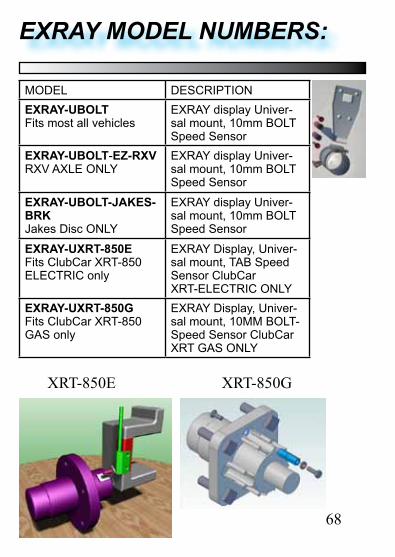
MODEL DESCRIPTIONEXRAY-UBOLTFits most all vehicles
EXRAY display Univer-sal mount, 10mm BOLT Speed Sensor
EXRAY-UBOLT-EZ-RXVRXV AXLE ONLY
EXRAY display Univer-sal mount, 10mm BOLT Speed Sensor
EXRAY-UBOLT-JAKES-BRKJakes Disc ONLY
EXRAY display Univer-sal mount, 10mm BOLT Speed Sensor
EXRAY-UXRT-850EFits ClubCar XRT-850 ELECTRIC only
EXRAY Display, Univer-sal mount, TAB Speed Sensor ClubCar XRT-ELECTRIC ONLY
EXRAY-UXRT-850GFits ClubCar XRT-850 GAS only
EXRAY Display, Univer-sal mount, 10MM BOLT-Speed Sensor ClubCar XRT GAS ONLY
XRT-850E XRT-850G
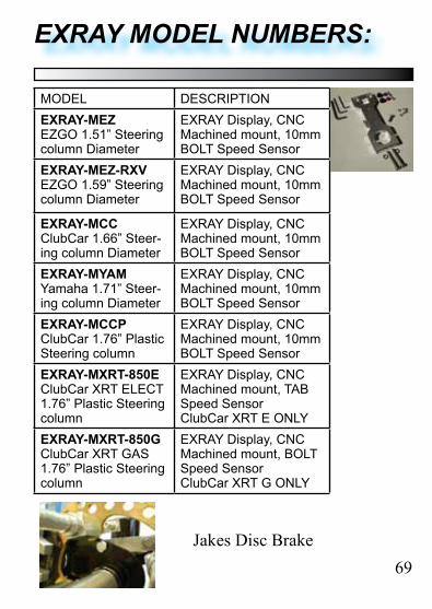
MODEL DESCRIPTIONEXRAY-MEZEZGO 1.51” Steering column Diameter
EXRAY Display, CNC Machined mount, 10mm BOLT Speed Sensor
EXRAY-MEZ-RXVEZGO 1.59” Steering column Diameter
EXRAY Display, CNC Machined mount, 10mm BOLT Speed Sensor
EXRAY-MCCClubCar 1.66” Steer-ing column Diameter
EXRAY Display, CNC Machined mount, 10mm BOLT Speed Sensor
EXRAY-MYAMYamaha 1.71” Steer-ing column Diameter
EXRAY Display, CNC Machined mount, 10mm BOLT Speed Sensor
EXRAY-MCCPClubCar 1.76” Plastic Steering column
EXRAY Display, CNC Machined mount, 10mm BOLT Speed Sensor
EXRAY-MXRT-850EClubCar XRT ELECT1.76” Plastic Steering column
EXRAY Display, CNC Machined mount, TAB Speed Sensor ClubCar XRT E ONLY
EXRAY-MXRT-850GClubCar XRT GAS1.76” Plastic Steering column
EXRAY Display, CNC Machined mount, BOLT Speed Sensor ClubCar XRT G ONLY
69
EXRAY MODEL NUMBERS:
Jakes Disc Brake

70
EXRAY MODEL NUMBERS:
MODEL DESCRIPTIONEXRAY DISPLAY Replacement digital display headKIT-EXRAY TEMP ASY200-003-CHT, 10mm Temp sensor,
ASY200-005-TMP, 72” extension cableKIT-EXRAY PWR Cable Power kit, 48”KIT-SPD BOLT Speed BOLT Sensor Kit, 65” cable 10mmKIT-SPD TAB Speed TAB Sensor Kit, 65” cable, XRTKIT-EX-RXV BKT RXV-Axle 10MM BOLT Bracket & HDWRKIT-JAKES-BRK Jakes disc bracket BRACKETS ONLYKIT-CC XRT-850G CRT-850G (Gas) Hub Mount HardwareKIT-UNIV BKT Universal Bracket mount w/hardwareKIT-MEZ EZ 1.51” CNC Machined mount w/HDWRKIT-MEX-RXV EZ 1.59” CNC Machined mount w/HDWRKIT-MCC CC 1.66” CNC Machined mount, HDWRKIT-MYAM YAM 1.71” CNC Machined mount, HDWRKIT-MCCP CC 1.76” CNC Machined mount, HDWR
for 1.76” PLASTIC TUBE, and CC-XRTASY200-003-CHT 10mm Temp sensor, 21” w/JST ConnASY200-005-TMP Replacement 72” Temperature Sensor
extension cable, w/JST ConnMET350-009-BCK Simple Universal display bkt no/hardwareEXRAY OP MAN Operators manual, EXRAYBATT-2032 Replacement CR2032 Lithium Battery
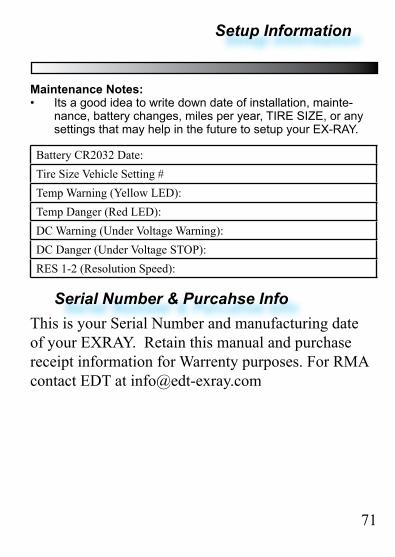
Maintenance Notes:• Its a good idea to write down date of installation, mainte-
nance, battery changes, miles per year, TIRE SIZE, or any settings that may help in the future to setup your EX-RAY.
Battery CR2032 Date:Tire Size Vehicle Setting #Temp Warning (Yellow LED): Temp Danger (Red LED):DC Warning (Under Voltage Warning):DC Danger (Under Voltage STOP):RES 1-2 (Resolution Speed):
71
Serial Number & Purcahse InfoThis is your Serial Number and manufacturing date of your EXRAY. Retain this manual and purchase receipt information for Warrenty purposes. For RMA contact EDT at [email protected]
Setup Information

EX-RAY
LIMITED WARRANTY Within 1 year from the date of purchase, EDT LLC, Will repair or replace, at it’s option, any EX-RAY™ which is deemed defective in workmanship or materials.
Please contact the dealer where the EX-RAY™ was purchased for assistance. Retain Proof Of Purchase.
DISCLAIMER OF IMPLIED WARRANTIES: EDT LLC SHALL IN NO EVENT BE LIABLE FOR DEATH, INJU-RIES TO PERSONS OR PROPERTY, OR FOR INCIDENTAL, CONTIN-GENT, OR CONSEQUENTIAL DAMAGES ARISING FROM THE USE OR MISUSE OF OUR PRODUCTS. EXCEPT SPECIFICALLY PROVIDED HEREIN, THERE ARE NO OTHER WARRANTIES, EXPRESS OR IMPLIED, INCLUDING, BUT NOT LIMITED TO, ANY IMPLIED WARRANTIES OF MERCHANTABIL-ITY OR FITNESS FOR A PARTICULAR PURPOSE. HOWEVER, SOME STATES DO NOT ALLOW LIMITATIONS ON HOW LONG AN IMPLIED WARRANTY LASTS, SO THE PRECEDING EXCLUSION MAY NOT APPLY TO YOU.
MADE IN AMERICA
EX-RAY™is a trademark of Energy Design Tek, LLC PO Box 190, Merlin, Oregon, 97532. USA
www.edt-exray.comPh: 541-441-6123 / FAX: 541-479-4605
File: Doc140-011-B_OP-EXRAY2-Operators Manual.pdfRevision B, 3-10-2013, Copyright ©2013