DIGITAL SERIES - Wibramet.pl
10
® CONTROLLER MCP12 DIGITAL SERIES MANUAL INSTRUCTIONS USE AND MAINTENANCE
Transcript of DIGITAL SERIES - Wibramet.pl
®
CONTROLLER MCP12
DIGITALSERIES
MAN
UAL
INST
RUCT
ION
S U
SE A
ND
MAI
NTE
NAN
CE
®
Code: MUMMCP12 Rev..: 03 Edit: E.Pedrazzi Date: 09/16 Sheet: 2
MODULE FOR ELECTROMAGNETIC VIBRATORS LINEAR - CIRCULAR - HOPPER MCP12
Vibrator Linear-Bowl-HopperSpeedInvert EnableStart RampStop RampMax LimitVibrating Frequency Half/Full Wave50/100 Hz(60/120Hz)
Sensor PNP 1 LinearInvert Sensor 1Delay ONDelay OFFTime Out (Empty warning)
Sensor PNP 2 Bowl FeederInvert Sensor 2Delay ONDelay OFFTime Out (Empty warning)
Sensor PNP 3-2° Air Flow/Present SignalInvert Sensore 3Delay ONDelay OFF
Output ValveOutput1: ON with bowl feeder delayed OFF bowl feederOutput2: Sensor 3 Airjet or “Present” signal Delay ON Delay OFF
LogicSensor 1/Sensor 3MIN-MAX Vibration levelsANDORTwin Track/Air
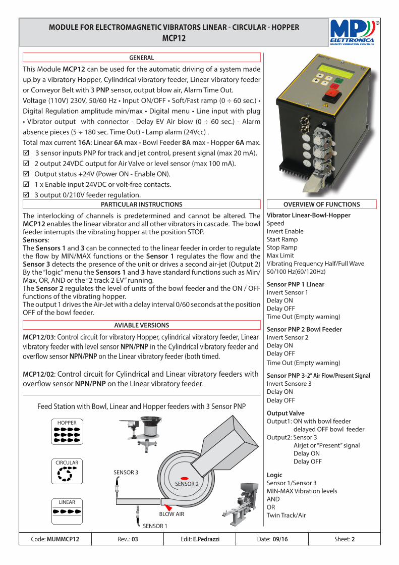
This Module MCP12 can be used for the automatic driving of a system made up by a vibratory Hopper, Cylindrical vibratory feeder, Linear vibratory feeder or Conveyor Belt with 3 PNP sensor, output blow air, Alarm Time Out.Voltage (110V) 230V, 50/60 Hz • Input ON/OFF • Soft/Fast ramp (0 ÷ 60 sec.) • Digital Regulation amplitude min/max • Digital menu • Line input with plug • Vibrator output with connector - Delay EV Air blow (0 ÷ 60 sec.) - Alarm absence pieces (5 ÷ 180 sec. Time Out) - Lamp alarm (24Vcc) .Total max current 16A: Linear 6A max - Bowl Feeder 8A max - Hopper 6A max.þ 3 sensor inputs PNP for track and jet control, present signal (max 20 mA).þ 2 output 24VDC output for Air Valve or level sensor (max 100 mA).þ Output status +24V (Power ON - Enable ON).þ 1 x Enable input 24VDC or volt-free contacts.þ 3 output 0/210V feeder regulation.
GENERAL
The interlocking of channels is predetermined and cannot be altered. The MCP12 enables the linear vibrator and all other vibrators in cascade. The bowl feeder interrupts the vibrating hopper at the position STOP.Sensors:The Sensors 1 and 3 can be connected to the linear feeder in order to regulate the flow by MIN/MAX functions or the Sensor 1 regulates the flow and the Sensor 3 detects the presence of the unit or drives a second air-jet (Output 2) By the “logic” menu the Sensors 1 and 3 have standard functions such as Min/Max, OR, AND or the “2 track 2 EV” running.The Sensor 2 regulates the level of units of the bowl feeder and the ON / OFF functions of the vibrating hopper.The output 1 drives the Air-Jet with a delay interval 0/60 seconds at the position OFF of the bowl feeder.
PARTICULAR INSTRUCTIONS OVERVIEW OF FUNCTIONS
HOPPER
CIRCULAR
LINEAR
BLOW AIR
SENSOR 1
SENSOR 2
SENSOR 3
MCP12/03: Control circuit for vibratory Hopper, cylindrical vibratory feeder, Linear vibratory feeder with level sensor NPN/PNP in the Cylindrical vibratory feeder and overflow sensor NPN/PNP on the Linear vibratory feeder (both timed.
MCP12/02: Control circuit for Cylindrical and Linear vibratory feeders with overflow sensor NPN/PNP on the Linear vibratory feeder.
AVIABLE VERSIONS
Feed Station with Bowl, Linear and Hopper feeders with 3 Sensor PNP
®
1 2 3 4 5 6 7 8 9 10 11 12 13 14 15 16
17
FUSE 10A
18 19 20 21 22 23 24 25 26 27 28 29 30 31 32
-24V
-24V
-24V
OU
T3
OU
T4
STAT
US
TOH
TOB
OU
T2-
OU
T1
FC4
FC3
FC1
FC2
Abi
lit.
+24V
+24V
+24V
Line
ar -
GN
D
Bow
l
Line
ar
GN
D
Hopp
er
Bow
l
GN
D
Hopp
er
GN
D
230V
230V
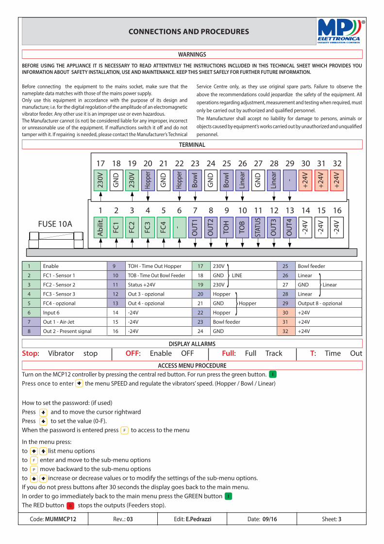
1 Enable 9 TOH - Time Out Hopper 17 230V 25 Bowl feeder
2 FC1 - Sensor 1 10 TOB - Time Out Bowl Feeder 18 GND LINE 26 Linear
3 FC2 - Sensor 2 11 Status +24V 19 230V 27 GND Linear
4 FC3 - Sensor 3 12 Out 3 - opzional 20 Hopper 28 Linear
5 FC4 - opzional 13 Out 4 - opzional 21 GND Hopper 29 Output 8 - opzional
6 Input 6 14 -24V 22 Hopper 30 +24V
7 Out 1 - Air-Jet 15 -24V 23 Bowl feeder 31 +24V
8 Out 2 - Present signal 16 -24V 24 GND 32 +24V
In the menu press:to list menu optionsto enter and move to the sub-menu optionsto move backward to the sub-menu optionsto increase or decrease values or to modify the settings of the sub-menu options.If you do not press buttons after 30 seconds the display goes back to the main menu.In order to go immediately back to the main menu press the GREEN buttonThe RED button stops the outputs (Feeders stop).
How to set the password: (if used)Press and to move the cursor rightwardPress to set the value (0-F).When the password is entered press to access to the menu
CONNECTIONS AND PROCEDURES
TERMINAL
DISPLAY ALLARMS
ACCESS MENU PROCEDURE
I
0
Stop: Vibrator stop OFF: Enable OFF Full: Full Track T: Time Out
Turn on the MCP12 controller by pressing the central red button. For run press the green button.Press once to enter the menu SPEED and regulate the vibrators’ speed. (Hopper / Bowl / Linear)
WARNINGS
BEFORE USING THE APPLIANCE IT IS NECESSARY TO READ ATTENTIVELY THE INSTRUCTIONS INCLUDED IN THIS TECHNICAL SHEET WHICH PROVIDES YOU INFORMATION ABOUT SAFETY INSTALLATION, USE AND MAINTENANCE. KEEP THIS SHEET SAFELY FOR FURTHER FUTURE INFORMATION.
Before connecting the equipment to the mains socket, make sure that the nameplate data matches with those of the mains power supply. Only use this equipment in accordance with the purpose of its design and manufacture; i.e. for the digital regolation of the amplitude of an electromagnetic vibrator feeder. Any other use it is an improper use or even hazardous. The Manufacturer cannot (is not) be considered liable for any improper, incorrect or unreasonable use of the equipment. If malfunctions switch it off and do not tamper with it. If repairing is needed, please contact the Manufacturer’s Technical
Service Centre only, as they use original spare parts. Failure to observe the above the recommendations could jeopardize the safety of the equipment. All operations regarding adjustment, measurement and testing when required, must only be carried out by authorized and qualified personnel. The Manufacturer shall accept no liability for damage to persons, animals or objects caused by equipment’s works carried out by unauthorized and unqualified personnel.
Code: MUMMCP12 Edit: E.Pedrazzi Sheet: 3
I
Rev..: 03 Date: 09/16
®
I
0
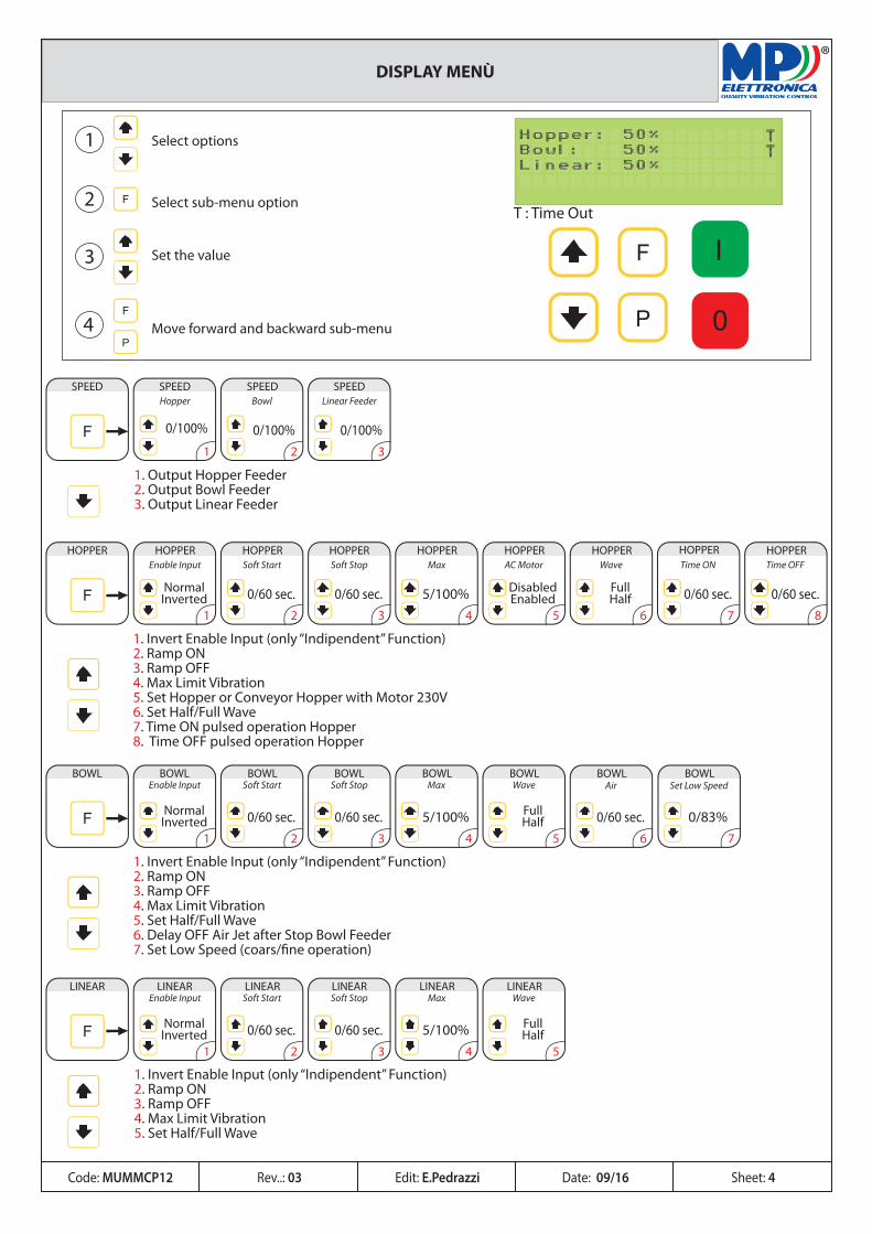
Select options
Select sub-menu option
Set the value
Move forward and backward sub-menu
SPEED
1
SPEED SPEED SPEED
0/100% 0/100% 0/100%2 3
1. Output Hopper Feeder2. Output Bowl Feeder3. Output Linear Feeder
Hopper Bowl Linear Feeder
BOWL
1
BOWL BOWL BOWL BOWL BOWL BOWLEnable Input Soft Start
0/60 sec.
Soft Stop
0/60 sec.
Max
5/100%
Wave
0/60 sec. 0/83%2 3 4 5 6
1. Invert Enable Input (only “Indipendent” Function)2. Ramp ON3. Ramp OFF4. Max Limit Vibration5. Set Half/Full Wave6. Delay OFF Air Jet after Stop Bowl Feeder7. Set Low Speed (coars/�ne operation)
NormalInverted
FullHalf
AirBOWL
7
Set Low Speed
HOPPER
1
HOPPER HOPPER HOPPER HOPPER HOPPERHOPPER HOPPER HOPPER
NormalInverted
DisabledEnabled
FullHalf0/60 sec. 0/60 sec. 5/100% 0/60 sec. 0/60 sec.
2 3 4 5 6 7 8
1. Invert Enable Input (only “Indipendent” Function)2. Ramp ON3. Ramp OFF4. Max Limit Vibration5. Set Hopper or Conveyor Hopper with Motor 230V6. Set Half/Full Wave7. Time ON pulsed operation Hopper8. Time OFF pulsed operation Hopper
Enable Input Soft Start Soft Stop Max AC Motor Wave Time ON Time OFF
NormalInverted
FullHalf
LINEAR
1
LINEAR LINEAR LINEAR LINEAR LINEAR
0/60 sec. 0/60 sec. 5/100%2 3 4 5
1. Invert Enable Input (only “Indipendent” Function)2. Ramp ON3. Ramp OFF4. Max Limit Vibration5. Set Half/Full Wave
Enable Input Soft Start Soft Stop Max Wave
T : Time Out
Code: MUMMCP12 Edit: E.Pedrazzi Sheet: 4
DISPLAY MENÙ
Rev..: 03 Date: 09/16
®
1
NormalInverted 0/60 sec. 0/60 sec. Enable
Disable 30/180 sec.2 3 4 5
Input ON Delay OFF Delay Enable Time out Time outHOPPER SENSOR HOPPER SENSORHOPPER SENSOR HOPPER SENSOR HOPPER SENSOR HOPPER SENSOR
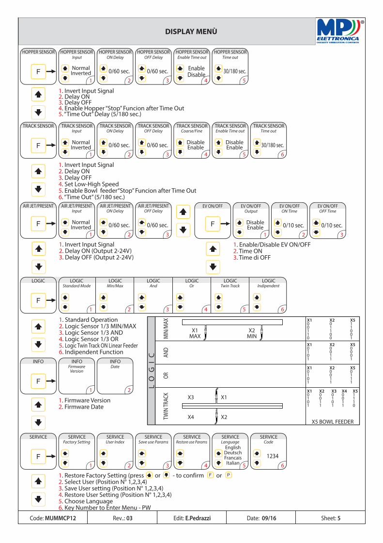
1. Invert Input Signal2. Delay ON 3. Delay OFF4. Enable Hopper “Stop” Funcion after Time Out5. “Time Out” Delay (5/180 sec.)
TRACK SENSOR
1
TRACK SENSOR TRACK SENSOR TRACK SENSOR TRACK SENSOR TRACK SENSOR TRACK SENSORInput ON Delay
0/60 sec.
OFF Delay
0/60 sec.
Coarse/Fine Enable Time out Time out
30/180 sec.2 3 4 5 6
NormalInverted
DisableEnable
DisableEnable
1. Invert Input Signal2. Delay ON 3. Delay OFF4. Set Low-High Speed5. Enable Bowl feeder“Stop” Funcion after Time Out6. “Time Out” (5/180 sec.)
AIR JET/PRESENT
1
AIR JET/PRESENT AIR JET/PRESENT AIR JET/PRESENTInput ON Delay
0/60 sec.
OFF Delay
0/60 sec.2 3
NormalInverted
1. Invert Input Signal 2. Delay ON (Output 2-24V)3. Delay OFF (Output 2-24V)
INFO
1
INFO INFOFirmware
VersionDate
2
1. Firmware Version2. Firmware Date
SERVICE
1
SERVICE SERVICE SERVICE SERVICE SERVICE SERVICEFactory Setting User Index Save use Params Restore use Params Language
EnglishDeutschFrancaisItalian
Code
12342 3 4 5 6
LOGIC
1
LOGIC LOGIC LOGIC LOGIC LOGICStandard Mode Min/Max And Or Twin Track
2 3 4 5
LOGICIndipendent
6
1. Standard Operation2. Logic Sensor 1/3 MIN/MAX3. Logic Sensor 1/3 AND4. Logic Sensor 1/3 OR5. Logic Twin Track ON Linear Feeder6. Indipendent Function
1. Restore Factory Setting (press or - to confirm or 2. Select User (Position N° 1,2,3,4)3. Save User setting (Position N° 1,2,3,4)4. Restore User Setting (Position N° 1,2,3,4)5. Choose Language6. Key Number to Enter Menu - PW
EV ON/OFF
1
EV ON/OFF EV ON/OFF EV ON/OFFOutput ON Time
0/10 sec.
OFF Time
0/10 sec.2 3
DisableEnable
1. Enable/Disable EV ON/OFF2. Time ON3. Time di OFF
Code: MUMMCP12 Edit: E.Pedrazzi Sheet: 5
DISPLAY MENÙ
Rev..: 03 Date: 09/16
LO
GI
C
MIN
/MAX
AND
ORTW
IN TR
ACK
X1MAX
X1
X2X5 BOWL FEEDER
X3
X4
X2MIN
X1 X2 X50 0 10 1 11 1 01 0 00 0 1X1 X2 X50 0 01 0 00 1 01 1 1
X1 X2 X50 0 01 0 10 1 11 1 1
X1 X2 X3 X4 X50 0 0 0 11 0 1 0 10 1 0 1 11 1 1 1 0
BOWL
0/60 sec.6
Air
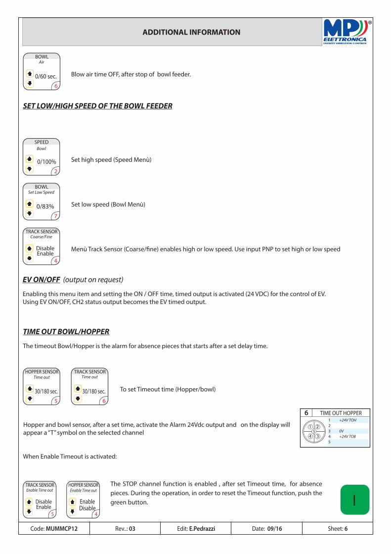
Blow air time OFF, after stop of bowl feeder.
SET LOW/HIGH SPEED OF THE BOWL FEEDER
SPEED
0/100%2
Bowl
Set high speed (Speed Menù)
0/83%
BOWL
7
Set Low Speed
Set low speed (Bowl Menù)
TRACK SENSORCoarse/Fine
4
DisableEnable
Menù Track Sensor (Coarse/fine) enables high or low speed. Use input PNP to set high or low speed
TIME OUT BOWL/HOPPER
The timeout Bowl/Hopper is the alarm for absence pieces that starts after a set delay time.
30/180 sec.5
Time outHOPPER SENSOR TRACK SENSOR
Time out
30/180 sec.6
To set Timeout time (Hopper/bowl)
When Enable Timeout is activated:
® ADDITIONAL INFORMATION
Hopper and bowl sensor, after a set time, activate the Alarm 24Vdc output and on the display will appear a “T” symbol on the selected channel
TRACK SENSOREnable Time out
5
DisableEnable
EnableDisable
4
Enable Time outHOPPER SENSOR The STOP channel function is enabled , after set Timeout time, for absence
pieces. During the operation, in order to reset the Timeout function, push the green button. I
Code: MUMMCP12 Edit: E.Pedrazzi Sheet: 6Rev..: 03 Date: 09/16
51 2
34
61 +24V TOH23 0V4 +24V TOB5
TIME OUT HOPPER
EV ON/OFF (output on request)
Enabling this menu item and setting the ON / OFF time, timed output is activated (24 VDC) for the control of EV.Using EV ON/OFF, CH2 status output becomes the EV timed output.
51 2
34
512 3 0V4 24V5
51 2
34
612 3 0V4 24V5
LOGIC
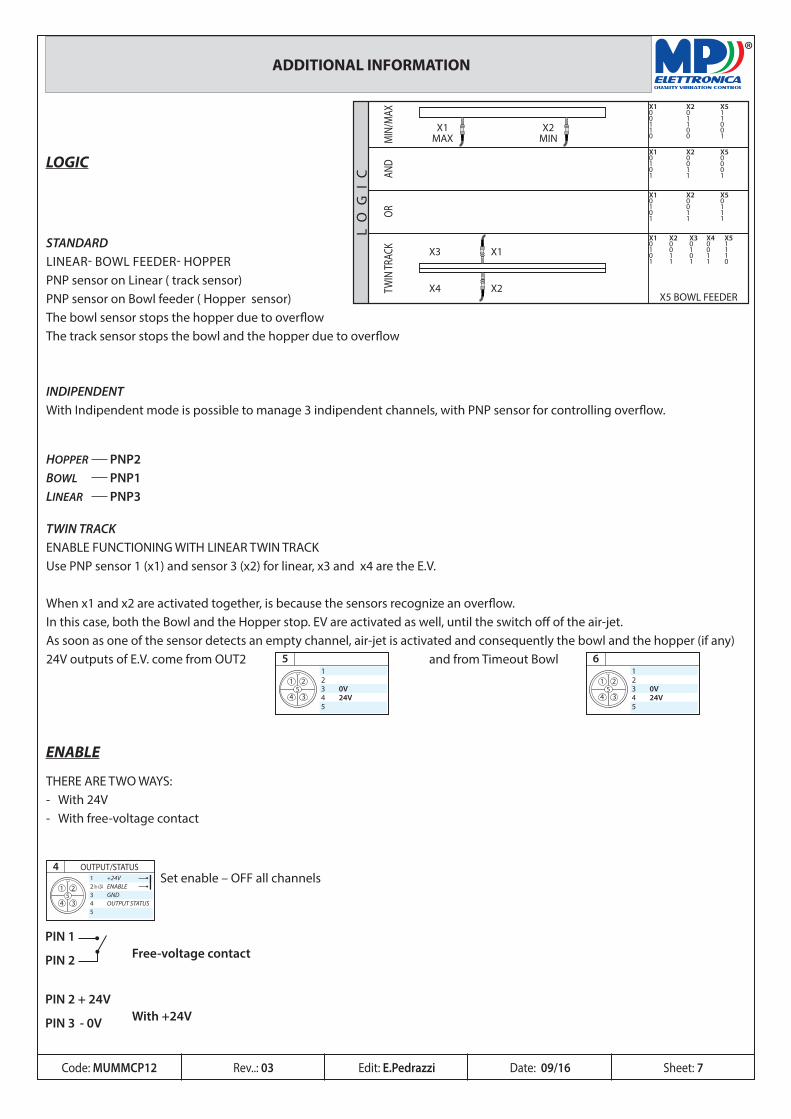
STANDARDLINEAR- BOWL FEEDER- HOPPERPNP sensor on Linear ( track sensor)PNP sensor on Bowl feeder ( Hopper sensor)The bowl sensor stops the hopper due to overflowThe track sensor stops the bowl and the hopper due to overflow
TWIN TRACKENABLE FUNCTIONING WITH LINEAR TWIN TRACKUse PNP sensor 1 (x1) and sensor 3 (x2) for linear, x3 and x4 are the E.V.
When x1 and x2 are activated together, is because the sensors recognize an overflow.In this case, both the Bowl and the Hopper stop. EV are activated as well, until the switch off of the air-jet. As soon as one of the sensor detects an empty channel, air-jet is activated and consequently the bowl and the hopper (if any)24V outputs of E.V. come from OUT2 and from Timeout Bowl
ENABLE
THERE ARE TWO WAYS:- With 24V- With free-voltage contact
PIN 2 + 24V
PIN 3 - 0V With +24V
® ADDITIONAL INFORMATION
Set enable – OFF all channels5
1 2
34
41 +24V2 In +24 ENABLE 3 GND4 OUTPUT STATUS5
OUTPUT/STATUS
PIN 1
PIN 2 Free-voltage contact
INDIPENDENTWith Indipendent mode is possible to manage 3 indipendent channels, with PNP sensor for controlling overflow.
HOPPER PNP2BOWL PNP1LINEAR PNP3
LO
GI
C
MIN
/MAX
AND
ORTW
IN TR
ACK
X1MAX
X1
X2X5 BOWL FEEDER
X3
X4
X2MIN
X1 X2 X50 0 10 1 11 1 01 0 00 0 1
X1 X2 X50 0 01 0 00 1 01 1 1
X1 X2 X50 0 01 0 10 1 11 1 1
X1 X2 X3 X4 X50 0 0 0 11 0 1 0 10 1 0 1 11 1 1 1 0
Code: MUMMCP12 Edit: E.Pedrazzi Sheet: 7Rev..: 03 Date: 09/16
®
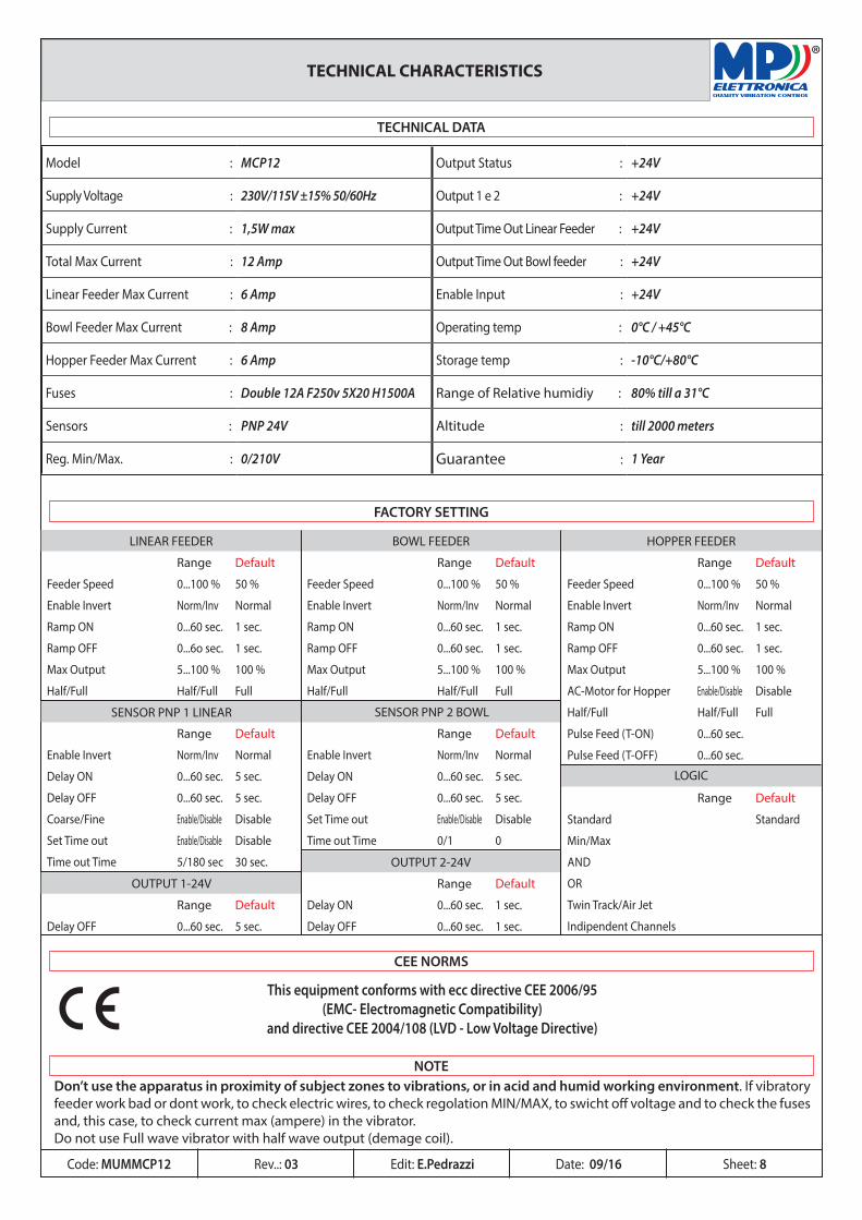
Range Default
Enable Invert Norm/Inv Normal
Delay ON 0...60 sec. 5 sec.
Delay OFF 0...60 sec. 5 sec.
Coarse/Fine Enable/Disable Disable
Set Time out Enable/Disable Disable
Time out Time 5/180 sec 30 sec.
Range Default
Feeder Speed 0...100 % 50 %
Enable Invert Norm/Inv Normal
Ramp ON 0...60 sec. 1 sec.
Ramp OFF 0...6o sec. 1 sec.
Max Output 5...100 % 100 %
Half/Full Half/Full Full
Range Default
Delay OFF 0...60 sec. 5 sec.
Range Default
Delay ON 0...60 sec. 1 sec.
Delay OFF 0...60 sec. 1 sec.
Range Default
Enable Invert Norm/Inv Normal
Delay ON 0...60 sec. 5 sec.
Delay OFF 0...60 sec. 5 sec.
Set Time out Enable/Disable Disable
Time out Time 0/1 0
Range Default
Standard Standard
Min/Max
AND
OR
Twin Track/Air Jet
Indipendent Channels
Range Default
Feeder Speed 0...100 % 50 %
Enable Invert Norm/Inv Normal
Ramp ON 0...60 sec. 1 sec.
Ramp OFF 0...60 sec. 1 sec.
Max Output 5...100 % 100 %
Half/Full Half/Full Full
Range Default
Feeder Speed 0...100 % 50 %
Enable Invert Norm/Inv Normal
Ramp ON 0...60 sec. 1 sec.
Ramp OFF 0...60 sec. 1 sec.
Max Output 5...100 % 100 %
AC-Motor for Hopper Enable/Disable Disable
Half/Full Half/Full Full
Pulse Feed (T-ON) 0...60 sec.
Pulse Feed (T-OFF) 0...60 sec.
OUTPUT 1-24V
OUTPUT 2-24V
LOGIC
SENSOR PNP 1 LINEAR SENSOR PNP 2 BOWL
HOPPER FEEDERBOWL FEEDERLINEAR FEEDER
TECHNICAL CHARACTERISTICS
Model : MCP12 Output Status : +24V
Supply Voltage : 230V/115V ±15% 50/60Hz Output 1 e 2 : +24V
Supply Current : 1,5W max Output Time Out Linear Feeder : +24V
Total Max Current : 12 Amp Output Time Out Bowl feeder : +24V
Linear Feeder Max Current : 6 Amp Enable Input : +24V
Bowl Feeder Max Current : 8 Amp Operating temp : 0°C / +45°C
Hopper Feeder Max Current : 6 Amp Storage temp : -10°C/+80°C
Fuses : Double 12A F250v 5X20 H1500A Range of Relative humidiy : 80% till a 31°C
Sensors : PNP 24V Altitude : till 2000 meters
Reg. Min/Max. : 0/210V Guarantee : 1 Year
This equipment conforms with ecc directive CEE 2006/95(EMC- Electromagnetic Compatibility)
and directive CEE 2004/108 (LVD - Low Voltage Directive)
CEE NORMS
Don’t use the apparatus in proximity of subject zones to vibrations, or in acid and humid working environment. If vibratory feeder work bad or dont work, to check electric wires, to check regolation MIN/MAX, to swicht off voltage and to check the fuses and, this case, to check current max (ampere) in the vibrator.Do not use Full wave vibrator with half wave output (demage coil).
NOTE
TECHNICAL DATA
FACTORY SETTING
Code: MUMMCP12 Edit: E.Pedrazzi Sheet: 8Rev..: 03 Date: 09/16
®
= =ø 5 mm
= =ø 5 mm
MCP 12
I
0 193
1
4
2
3
1
4
2
3
1
4
2
3
1
4
2
3
1
4
2
3
1
4
2
3
5
6
7
8
9
10
2
1
3
4
130205
200
1PE
23
1PE
23
1PE
23
1PE
23
AC
HT
UN
G!
WA
RN
ING
!
TO
GL
IER
E L
A T
EN
SIO
NE
PR
IMA
DI
AP
RIR
EC
OU
PE
R
LE
C
OU
RA
NT
A
VA
NT
D
'OU
VR
IRS
PA
NN
UN
G U
NT
ER
BR
EC
HE
N B
EV
OR
OE
FF
NE
NT
UR
N O
FF
TH
E P
OW
ER
BE
FO
RE
OP
EN
ING
PE
RIC
OL
O!
DA
NG
ER
!
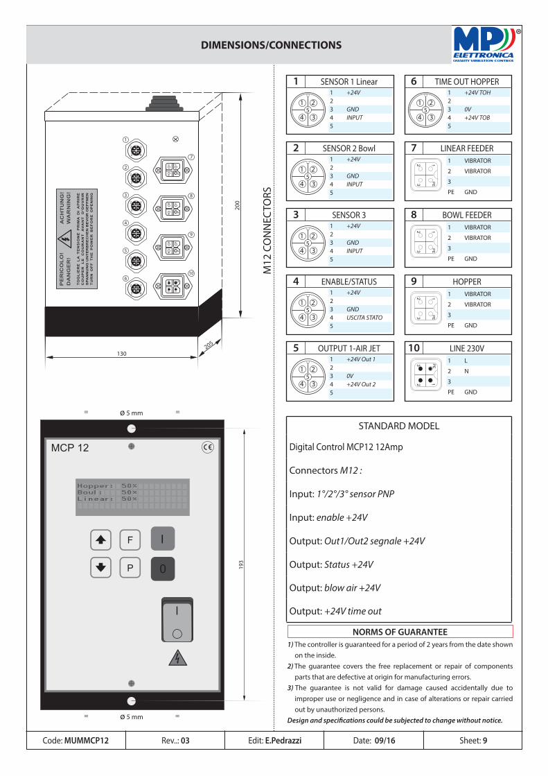
DIMENSIONS/CONNECTIONS
STANDARD MODEL
Digital Control MCP12 12Amp
Connectors M12 :
Input: 1°/2°/3° sensor PNP
Input: enable +24V
Output: Out1/Out2 segnale +24V
Output: Status +24V
Output: blow air +24V
Output: +24V time out
51 2
34
11 +24V23 GND4 INPUT5
SENSOR 1 Linear
51 2
34
61 +24V TOH23 0V4 +24V TOB5
TIME OUT HOPPER
51 2
34
21 +24V23 GND4 INPUT5
SENSOR 2 Bowl
51 2
34
31 +24V23 GND4 INPUT5
SENSOR 3
51 2
34
41 +24V23 GND4 USCITA STATO5
ENABLE/STATUS
PE3
2 1
91 VIBRATOR
2 VIBRATOR
3
PE GND
HOPPER
51 2
34
51 +24V Out 123 0V4 +24V Out 25
OUTPUT 1-AIR JET
M12
CO
NN
ECTO
RS
PE
23
1
101 L
2 N
3
PE GND
LINE 230V
PE3
2 1
81 VIBRATOR
2 VIBRATOR
3
PE GND
BOWL FEEDER
PE3
2 1
71 VIBRATOR
2 VIBRATOR
3
PE GND
LINEAR FEEDER
Code: MUMMCP12 Edit: E.Pedrazzi Sheet: 9
1) The controller is guaranteed for a period of 2 years from the date shown on the inside. 2) The guarantee covers the free replacement or repair of components parts that are defective at origin for manufacturing errors. 3) The guarantee is not valid for damage caused accidentally due to improper use or negligence and in case of alterations or repair carried out by unauthorized persons. Design and specifications could be subjected to change without notice.
NORMS OF GUARANTEE
Rev..: 03 Date: 09/16
®
MP Elettronica srlvia Torino 6220099 Sesto San Giovanni -MI - ITALYtel.: +39 (02) 24 03 864Fax: +39 (02) 24 00 [email protected]
HEADQUARTERS
MP Elettronica srlvia Campagna 1021041 Albizzate (VA) - ITALYtel.: +39 (0331) 98 52 10Fax: +39 (0331) 98 52 [email protected]
PRODUCTION UNIT 1 - WAREHOUSE
MP Elettronica srlvia Torino 8020099 Sesto San Giovanni -MI - ITALYtel.: +39 (02) 39 66 23 68Fax: +39 (02) 24 00 [email protected]
PRODUCTION UNIT2
CUSTOMER SERVICE 24/24HOT LINE : VOICE - WHATSAPP
+39 393 925 6076
+39 339 449 4940
+39 339 449 4940
+39 393 958 2535