Digital Scanned Laser Light Sheet Fluorescence Microscopy Lab/Keller...Digital Scanned Laser Light...
13
Digital Scanned Laser Light Sheet Fluorescence Microscopy Philipp J. Keller and Ernst H.K. Stelzer INTRODUCTION Modern applications in the life sciences are frequently based on in vivo imaging of biological speci- mens, a domain for which light microscopy approaches are typically best suited. Often, quantitative information must be obtained from large multicellular organisms on the cellular or even subcellular level and with a good temporal resolution. However, this usually requires a combination of conflicting features: high imaging speed, low photobleaching, and low phototoxicity in the specimen, good three-dimensional (3D) resolution, an excellent signal-to-noise ratio, and multiple-view imaging capa- bility. The latter feature refers to the capability of recording a specimen along multiple directions, which is crucial for the imaging of large specimens with strong light-scattering or light-absorbing tissue properties. An imaging technique that fulfills these requirements is essential for many key applications: For example, studying fast cellular processes over long periods of time, imaging entire embryos throughout development, or reconstructing the formation of morphological defects in mutants. Here, we discuss digital scanned laser light sheet fluorescence microscopy (DSLM) as a novel tool for quantitative in vivo imaging in the post-genomic era and show how this emerging technique relates to the currently most widely applied 3D microscopy techniques in biology: confocal fluores- cence microscopy and two-photon microscopy. RELATED INFORMATION The power of advanced in vivo imaging technology is illustrated by the use of fast fluorescence microscopy to study the dynamics of embryonic development (Vermot et al. 2008). Techniques that facilitate the imaging of large specimens with strong light-scattering or light-absorbing tissue properties are described by Huisken et al. (2004), Swoger et al. (2007), and Keller et al. (2008a). OVERVIEW DSLM belongs to the family of light-sheet-based fluorescence microscopy (LSFM). In contrast to conventional and confocal epifluorescence microscopes, which employ the same lens for fluorescence excitation and detection, LSFM relies on the principle of sample illumination with a planar light sheet perpendicular to the axis of fluorescence detection (Siedentopf and Zsigmondy 1903; Voie et al. 1993). Optical sectioning arises from the overlap between the focal plane of the fluorescence detection system and the excitation light sheet (Fig. 1). Conventional, as well as confocal epifluorescence, microscopes excite fluorophores along the entire common illumination/detection axis. Hence, when recording a single plane, they cause photo- bleaching and photodamage everywhere in the specimen (Pawley 2006). The 3D resolution of con- focal fluorescence microscopes is achieved by discriminating against the light that is emitted outside the focal plane. In contrast, LSFM provides optical sectioning directly: Fluorophores are only excited in the illuminated plane, and thus photobleaching and other photoinduced damages are completely avoided outside the thin volume of interest (Fig. 1). Thereby, LSFM greatly reduces phototoxic effects (Keller et al. 2007), which actually cause problems in all experiments that rely on imaging. This circumstance provides LSFM with a decisive advantage in the fast imaging of sensitive biological © 2010 Cold Spring Harbor Laboratory Press 1 Vol. 2010, Issue 5, May Adapted from Live Cell Imaging, 2nd edition (ed. Goldman et al.). CSHL Press, Cold Spring Harbor, NY, USA, 2010. Cite as: Cold Spring Harb Protoc; 2010; doi:10.1101/pdb.top78 www.cshprotocols.org Topic Introduction Cold Spring Harbor Laboratory Press at JANELIA FARM RESEARCH CAMPUS on July 11, 2012 - Published by http://cshprotocols.cshlp.org/ Downloaded from
Transcript of Digital Scanned Laser Light Sheet Fluorescence Microscopy Lab/Keller...Digital Scanned Laser Light...
Digital Scanned Laser Light Sheet Fluorescence Microscopy
Philipp J. Keller and Ernst H.K. Stelzer
INTRODUCTION
Modern applications in the life sciences are frequently based on in vivo imaging of biological speci-mens, a domain for which light microscopy approaches are typically best suited. Often, quantitativeinformation must be obtained from large multicellular organisms on the cellular or even subcellularlevel and with a good temporal resolution. However, this usually requires a combination of conflictingfeatures: high imaging speed, low photobleaching, and low phototoxicity in the specimen, goodthree-dimensional (3D) resolution, an excellent signal-to-noise ratio, and multiple-view imaging capa-bility. The latter feature refers to the capability of recording a specimen along multiple directions,which is crucial for the imaging of large specimens with strong light-scattering or light-absorbing tissue properties. An imaging technique that fulfills these requirements is essential for many key applications: For example, studying fast cellular processes over long periods of time, imaging entireembryos throughout development, or reconstructing the formation of morphological defects inmutants. Here, we discuss digital scanned laser light sheet fluorescence microscopy (DSLM) as a noveltool for quantitative in vivo imaging in the post-genomic era and show how this emerging techniquerelates to the currently most widely applied 3D microscopy techniques in biology: confocal fluores-cence microscopy and two-photon microscopy.
RELATED INFORMATION
The power of advanced in vivo imaging technology is illustrated by the use of fast fluorescencemicroscopy to study the dynamics of embryonic development (Vermot et al. 2008). Techniques that facilitate the imaging of large specimens with strong light-scattering or light-absorbing tissueproperties are described by Huisken et al. (2004), Swoger et al. (2007), and Keller et al. (2008a).
OVERVIEW
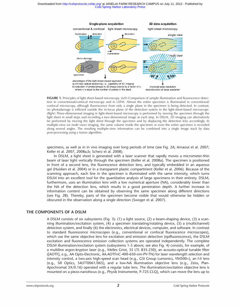
DSLM belongs to the family of light-sheet-based fluorescence microscopy (LSFM). In contrast to conventional and confocal epifluorescence microscopes, which employ the same lens for fluorescenceexcitation and detection, LSFM relies on the principle of sample illumination with a planar light sheetperpendicular to the axis of fluorescence detection (Siedentopf and Zsigmondy 1903; Voie et al.1993). Optical sectioning arises from the overlap between the focal plane of the fluorescence detection system and the excitation light sheet (Fig. 1).
Conventional, as well as confocal epifluorescence, microscopes excite fluorophores along theentire common illumination/detection axis. Hence, when recording a single plane, they cause photo-bleaching and photodamage everywhere in the specimen (Pawley 2006). The 3D resolution of con-focal fluorescence microscopes is achieved by discriminating against the light that is emitted outsidethe focal plane. In contrast, LSFM provides optical sectioning directly: Fluorophores are only excitedin the illuminated plane, and thus photobleaching and other photoinduced damages are completelyavoided outside the thin volume of interest (Fig. 1). Thereby, LSFM greatly reduces phototoxic effects(Keller et al. 2007), which actually cause problems in all experiments that rely on imaging. This circumstance provides LSFM with a decisive advantage in the fast imaging of sensitive biological
© 2010 Cold Spring Harbor Laboratory Press 1 Vol. 2010, Issue 5, May
Adapted from Live Cell Imaging, 2nd edition (ed. Goldman et al.).CSHL Press, Cold Spring Harbor, NY, USA, 2010.Cite as: Cold Spring Harb Protoc; 2010; doi:10.1101/pdb.top78 www.cshprotocols.org
Topic Introduction
Cold Spring Harbor Laboratory Press at JANELIA FARM RESEARCH CAMPUS on July 11, 2012 - Published by http://cshprotocols.cshlp.org/Downloaded from
www.cshprotocols.org 2 Cold Spring Harbor Protocols
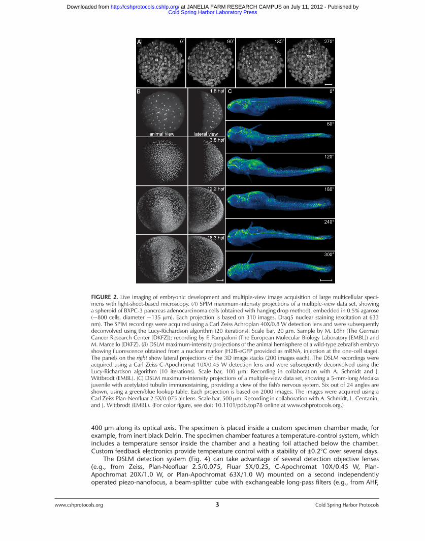
specimens, as well as in in vivo imaging over long periods of time (see Fig. 2A; Arnaout et al. 2007;Keller et al. 2007, 2008a,b; Scherz et al. 2008).
In DSLM, a light sheet is generated with a laser scanner that rapidly moves a micrometer-thinbeam of laser light vertically through the specimen (Keller et al. 2008a). The specimen is positionedin front of a second lens, the fluorescence detection lens, and typically embedded in an aqueous gel (Huisken et al. 2004) or in a transparent plastic compartment (Keller et al. 2006). Because of thescanning approach, each line in the specimen is illuminated with the same intensity, which turnsDSLM into an excellent tool for the quantitative analysis of large specimens in their entirety. DSLM,furthermore, uses an illumination lens with a low numerical aperture (NA), considerably lower thanthe NA of the detection lens, which results in a good penetration depth. A further increase in information content can be obtained by observing the same specimen along different directions (see Fig. 2B). Thereby, parts of the specimen become visible that would otherwise be hidden orobscured in the observation along a single direction (Swoger et al. 2007).
THE COMPONENTS OF A DSLM
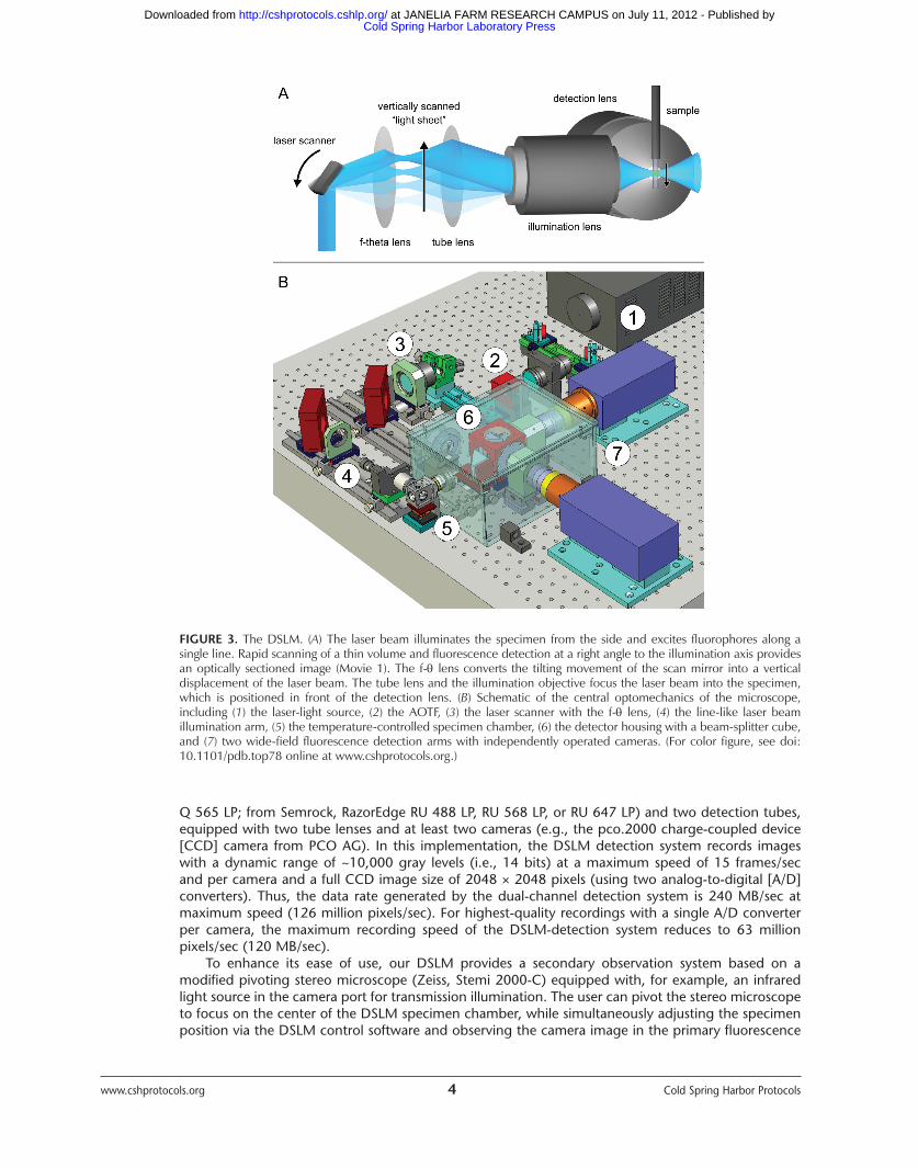
A DSLM consists of six subsystems (Fig. 3): (1) a light source, (2) a beam-shaping device, (3) a scan-ning illumination/excitation system, (4) a specimen translating/rotating device, (5) a (multichannel)detection system, and finally (6) the electronics, electrical devices, computer, and software. In contrastto standard fluorescence microscopes (e.g., conventional or confocal fluorescence microscopes),which use the same objective lens for excitation and emission detection (epifluorescence), the DSLMexcitation and fluorescence emission collection systems are operated independently. The completeDSLM illumination/excitation system (subsystems 1-3 above; see also Fig. 4) consists, for example, ofa multiline argon-krypton laser (e.g., Melles Griot, 35 LTL 835-230), an acousto-optical tunable filter([AOTF], e.g., AA Opto-Electronic, AA.AOTFnC-400-650-nm-PV-TN) for laser wavelength selection andintensity control, a two-axis high-speed scan head (e.g., GSI Group Lumonics, VM500+), an f- lens(e.g., Sill Optics, S4LFT0061/065), and a low-NA illumination objective lens (e.g., Zeiss, Plan-Apochromat 5X/0.16) operated with a regular tube lens. The illumination/excitation objective lens ismounted on a piezo-nanofocus (e.g., Physik Instrumente, P-725.CLQ), which can move the lens up to
FIGURE 1. Principles of light sheet-based microscopy. (Left) Comparison of sample illumination and fluorescence detec-tion in conventional/confocal microscopy and in LSFM. Almost the entire specimen is illuminated in conventional/confocal microscopy, although fluorescence from only a single plane in the specimen is being detected. In contrast, no photodamage is inflicted outside the in-focus plane of the detection system in the light-sheet-based microscope.(Right) Three-dimensional imaging in light-sheet-based microscopy is performed by moving the specimen through thelight sheet in small steps and recording a two-dimensional image at each step. In DSLM, 3D imaging can alternativelybe performed by moving the light sheet through the specimen and by displacing the detection lens accordingly. In multiple-view (or multi view) imaging, the same volume inside the specimen or even the entire specimen is recordedalong several angles. The resulting multiple-view information can be combined into a single image stack by data post-processing using a fusion algorithm.
Cold Spring Harbor Laboratory Press at JANELIA FARM RESEARCH CAMPUS on July 11, 2012 - Published by http://cshprotocols.cshlp.org/Downloaded from
400 µm along its optical axis. The specimen is placed inside a custom specimen chamber made, forexample, from inert black Delrin. The specimen chamber features a temperature-control system, whichincludes a temperature sensor inside the chamber and a heating foil attached below the chamber.Custom feedback electronics provide temperature control with a stability of ±0.2°C over several days.
The DSLM detection system (Fig. 4) can take advantage of several detection objective lenses (e.g., from Zeiss, Plan-Neofluar 2.5/0.075, Fluar 5X/0.25, C-Apochromat 10X/0.45 W, Plan-Apochromat 20X/1.0 W, or Plan-Apochromat 63X/1.0 W) mounted on a second independently operated piezo-nanofocus, a beam-splitter cube with exchangeable long-pass filters (e.g., from AHF,
www.cshprotocols.org 3 Cold Spring Harbor Protocols
FIGURE 2. Live imaging of embryonic development and multiple-view image acquisition of large multicellular speci-mens with light-sheet-based microscopy. (A) SPIM maximum-intensity projections of a multiple-view data set, showinga spheroid of BXPC-3 pancreas adenocarcinoma cells (obtained with hanging drop method), embedded in 0.5% agarose(~800 cells, diameter ~135 m). Each projection is based on 310 images. Draq5 nuclear staining (excitation at 633nm). The SPIM recordings were acquired using a Carl Zeiss Achroplan 40X/0.8 W detection lens and were subsequentlydeconvolved using the Lucy-Richardson algorithm (20 iterations). Scale bar, 20 m. Sample by M. Löhr (The GermanCancer Research Center [DKFZ]); recording by F. Pampaloni (The European Molecular Biology Laboratory [EMBL]) andM. Marcello (DKFZ). (B) DSLM maximum-intensity projections of the animal hemisphere of a wild-type zebrafish embryoshowing fluorescence obtained from a nuclear marker (H2B-eGFP provided as mRNA, injection at the one-cell stage).The panels on the right show lateral projections of the 3D image stacks (200 images each). The DSLM recordings wereacquired using a Carl Zeiss C-Apochromat 10X/0.45 W detection lens and were subsequently deconvolved using theLucy-Richardson algorithm (10 iterations). Scale bar, 100 m. Recording in collaboration with A. Schmidt and J.Wittbrodt (EMBL). (C) DSLM maximum-intensity projections of a multiple-view data set, showing a 5-mm-long Medakajuvenile with acetylated tubulin immunostaining, providing a view of the fish’s nervous system. Six out of 24 angles areshown, using a green/blue lookup table. Each projection is based on 2000 images. The images were acquired using aCarl Zeiss Plan-Neofluar 2.5X/0.075 air lens. Scale bar, 500 m. Recording in collaboration with A. Schmidt, L. Centanin,and J. Wittbrodt (EMBL). (For color figure, see doi: 10.1101/pdb.top78 online at www.cshprotocols.org.)
Cold Spring Harbor Laboratory Press at JANELIA FARM RESEARCH CAMPUS on July 11, 2012 - Published by http://cshprotocols.cshlp.org/Downloaded from
www.cshprotocols.org 4 Cold Spring Harbor Protocols
FIGURE 3. The DSLM. (A) The laser beam illuminates the specimen from the side and excites fluorophores along a single line. Rapid scanning of a thin volume and fluorescence detection at a right angle to the illumination axis providesan optically sectioned image (Movie 1). The f- lens converts the tilting movement of the scan mirror into a vertical displacement of the laser beam. The tube lens and the illumination objective focus the laser beam into the specimen,which is positioned in front of the detection lens. (B) Schematic of the central optomechanics of the microscope, including (1) the laser-light source, (2) the AOTF, (3) the laser scanner with the f- lens, (4) the line-like laser beam illumination arm, (5) the temperature-controlled specimen chamber, (6) the detector housing with a beam-splitter cube,and (7) two wide-field fluorescence detection arms with independently operated cameras. (For color figure, see doi:10.1101/pdb.top78 online at www.cshprotocols.org.)
Q 565 LP; from Semrock, RazorEdge RU 488 LP, RU 568 LP, or RU 647 LP) and two detection tubes,equipped with two tube lenses and at least two cameras (e.g., the pco.2000 charge-coupled device[CCD] camera from PCO AG). In this implementation, the DSLM detection system records imageswith a dynamic range of ~10,000 gray levels (i.e., 14 bits) at a maximum speed of 15 frames/sec and per camera and a full CCD image size of 2048 × 2048 pixels (using two analog-to-digital [A/D]converters). Thus, the data rate generated by the dual-channel detection system is 240 MB/sec atmaximum speed (126 million pixels/sec). For highest-quality recordings with a single A/D converterper camera, the maximum recording speed of the DSLM-detection system reduces to 63 million pixels/sec (120 MB/sec).
To enhance its ease of use, our DSLM provides a secondary observation system based on a modified pivoting stereo microscope (Zeiss, Stemi 2000-C) equipped with, for example, an infraredlight source in the camera port for transmission illumination. The user can pivot the stereo microscopeto focus on the center of the DSLM specimen chamber, while simultaneously adjusting the specimenposition via the DSLM control software and observing the camera image in the primary fluorescence
Cold Spring Harbor Laboratory Press at JANELIA FARM RESEARCH CAMPUS on July 11, 2012 - Published by http://cshprotocols.cshlp.org/Downloaded from
and/or transmission detection system. The direct observation using the stereomicroscope simplifiesand speeds up specimen positioning and specimen orientation for optimal DSLM-imaging conditionsin the primary detection system (thereby also minimizing the energy load on the specimen).
The illumination and detection subsystems are complemented by a specimen-positioning system,composed of a set of three linear translation stages (Physik Instrumente, M-111K028) and one micro-rotation stage (Physik Instrumente, M-116.DG). The rotation stage with its customized port providesconnectors for anodized aluminum specimen holders that hold glass capillaries and plastic syringes.
The operating computer for our DSLM implementation provides four central processing units(CPUs, Intel, Core 2 Quad Q6600 2.4 GHz). The operating software uses two physical CPUs exclusivelyfor the communication with the two camera pipelines, while the remaining two CPUs handle thegraphical user interface, subroutines for real-time image processing, and the communication with themain electronics hub. The mass storage device is a high-performance hardware RAID (redundant arrayof independent disks) controller (Promise, SuperTrak EX8350) with two RAID-0 dual-disk arrays (one per camera), each with 1.5 terabyte (TB) of disk space. The recorded images are written in analternating manner for the independent RAID systems, thereby doubling the maximum manageabledata rate and allowing for operation of the dual-camera detection system at the speed limit of thecameras’ A/D converters. Dual-camera data transfer is facilitated via a dual Camera Link controller card (National Instruments, PCIe-1430), installed in the acquisition computer. The other electronicscontroller cards are located in the DSLM electronics hub, which is attached to the computer via an Ethernet-linked bus extender (Hartmann Elektronik, StarFabric Bridge). The electronics hubincludes the scan controller (GSI Group, Lumonics, HC/3), a four-channel stage controller (PhysikInstrumente, C-843.41), two multichannel input/output controllers (National Instruments, PCI-6733),and the custom mainframe relay system. The AOTF beam control unit (AA Opto-Electronic,AA.MOD.8C-C**-75.158.24VDC) with an independent linear power supply (Kniel, CA 24.2,5), thedual-channel scanner drivers (GSI Group, Lumonics, MiniSAX) with dedicated linear power supplies(Kniel, CA 15.4), and the custom environmental control system for the specimen chamber are in aseparate crate.
We developed custom control software for microscope operation. The programming language C#was used for the user interface and the high-level control layers, and the programming language C++was used for lower-level hardware communication.
THE DSLM ILLUMINATION SYSTEM
One of the fundamental novel ideas of the DSLM concept is the use of laser scanners to create a two-dimensional sample illumination profile perpendicular to the detection axis. In the standard mode ofDSLM operation, one of the scan mirrors of the scan head moves at a constant speed within a prede-fined angular range. An f- lens converts the angular scan range of the laser beam into a vertical setof parallel beams. Because of the scanning approach, a single diffraction-limited beam of light
www.cshprotocols.org 5 Cold Spring Harbor Protocols
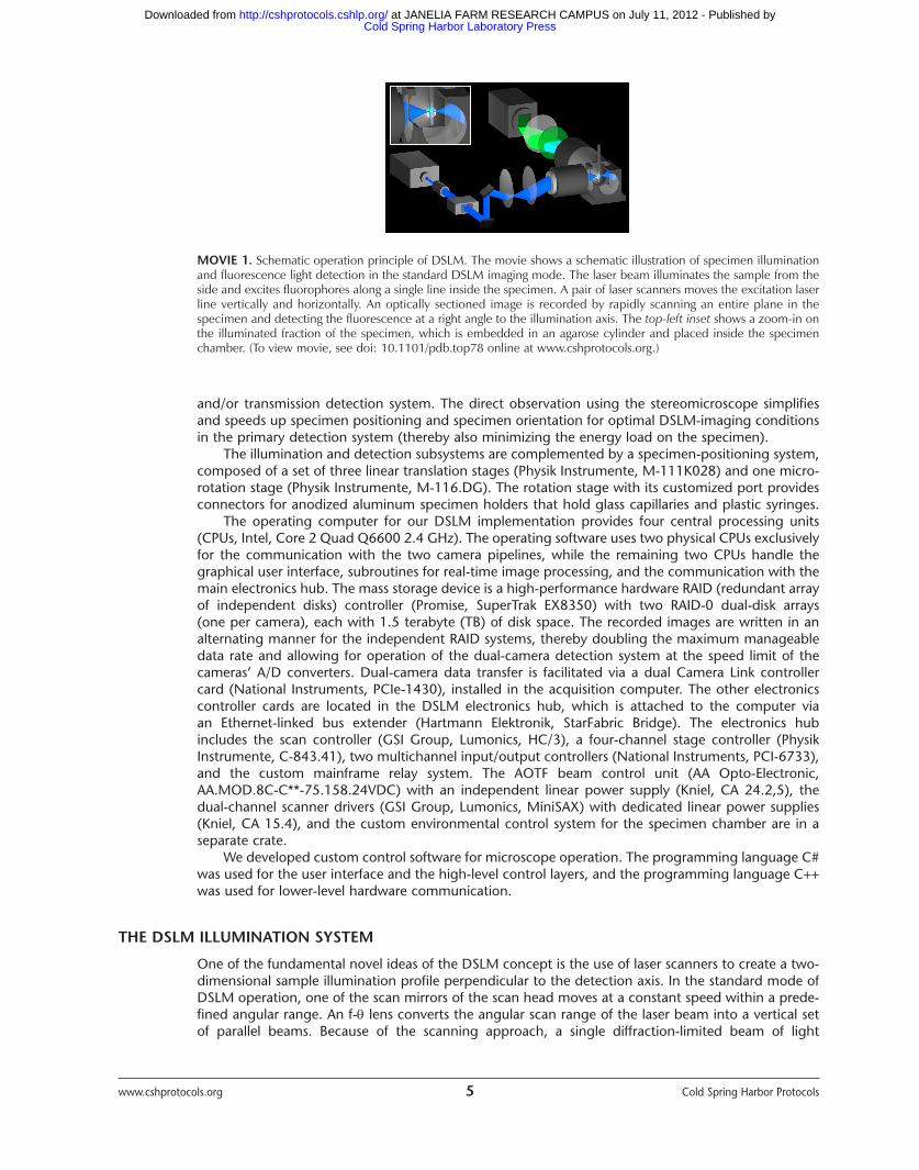
MOVIE 1. Schematic operation principle of DSLM. The movie shows a schematic illustration of specimen illuminationand fluorescence light detection in the standard DSLM imaging mode. The laser beam illuminates the sample from theside and excites fluorophores along a single line inside the specimen. A pair of laser scanners moves the excitation laserline vertically and horizontally. An optically sectioned image is recorded by rapidly scanning an entire plane in thespecimen and detecting the fluorescence at a right angle to the illumination axis. The top-left inset shows a zoom-in onthe illuminated fraction of the specimen, which is embedded in an agarose cylinder and placed inside the specimenchamber. (To view movie, see doi: 10.1101/pdb.top78 online at www.cshprotocols.org.)
Cold Spring Harbor Laboratory Press at JANELIA FARM RESEARCH CAMPUS on July 11, 2012 - Published by http://cshprotocols.cshlp.org/Downloaded from
www.cshprotocols.org 6 Cold Spring Harbor Protocols
illuminates the sample at any time point along a well-defined line in space. Integration over time andspace results in the illumination of an entire plane. Thus, to obtain a two-dimensional image, the camera integrates the signal while the laser scanners illuminate the respective plane in the detectionsystem’s field of view. By using a constant scan speed, a homogeneous light-sheet-like profile is generated (i.e., all horizontal lines are illuminated with the same light intensity). Because of the highscan speed, the entire two-dimensional profile can be created within <1 msec, irrespective of theextent of the field of view.
At any time point during the illumination process, the entire laser intensity (as determined by thesetting of the AOTF) is focused into a single diffraction-limited line. In previous light sheet microscopeimplementations (e.g., single plane illumination microscopy [SPIM]), apertures are necessary to shapethe intensity profile (resulting in an average illumination efficiency of 3%). In contrast, the DSLM illumination efficiency of 95% is only limited by the losses at the mirrors and lenses, which amount toconsiderably <1% per surface (and <5% in total). In addition to the high illumination efficiency, thescanning approach provides a precise control over the vertical extent of the illumination profile.
THE DSLM DETECTION SYSTEM
The main features of the DSLM detection system are (1) a quasi-parallelized detection concept thatuses two cameras simultaneously, (2) the possibility of avoiding moving elements such as shutters orfilter wheels, (3) cameras with a very large field of view, (4) a minimal number of optical elements,and (5) an electronics concept that allows us to independently address all components digitally andin parallel. In combination, these features maximize the imaging speed.
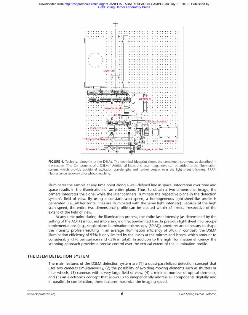
FIGURE 4. Technical blueprint of the DSLM. The technical blueprint shows the complete instrument, as described inthe section “The Components of a DSLM.” Additional lasers and beam expanders can be added to the illumination system, which provide additional excitation wavelengths and further control over the light sheet thickness. FRAP:Fluorescence recovery after photobleaching.
Cold Spring Harbor Laboratory Press at JANELIA FARM RESEARCH CAMPUS on July 11, 2012 - Published by http://cshprotocols.cshlp.org/Downloaded from
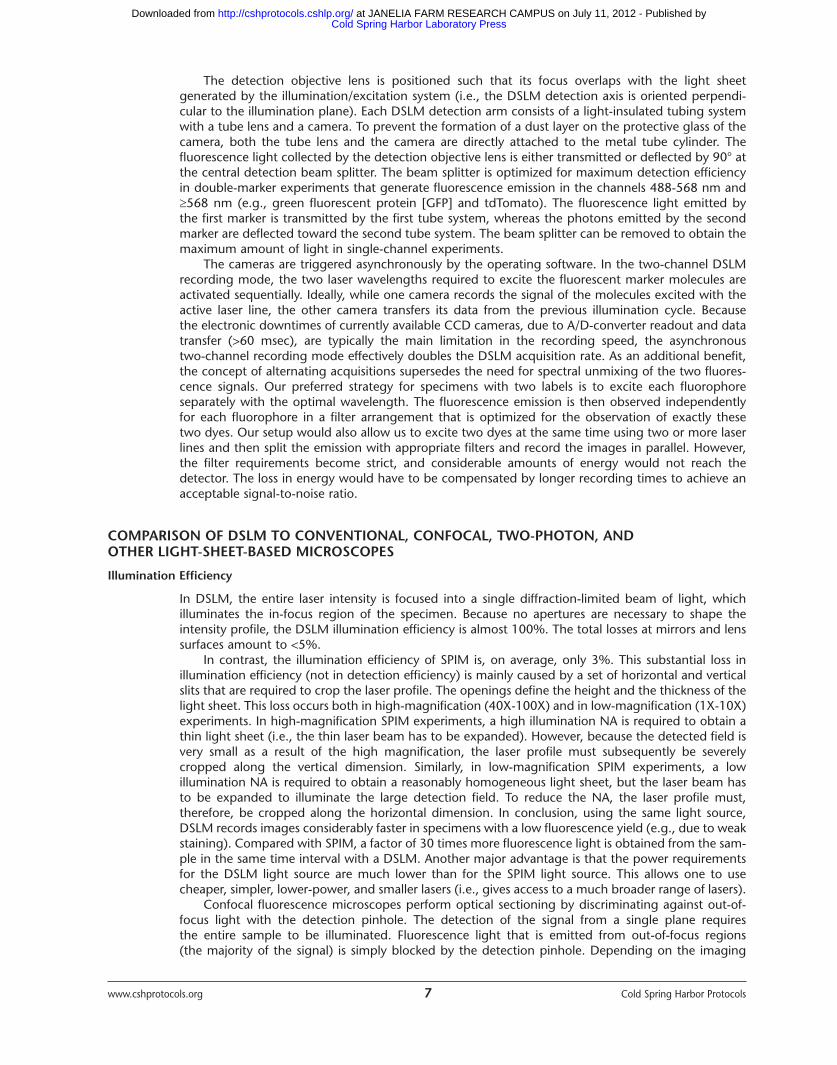
The detection objective lens is positioned such that its focus overlaps with the light sheet generated by the illumination/excitation system (i.e., the DSLM detection axis is oriented perpendi-cular to the illumination plane). Each DSLM detection arm consists of a light-insulated tubing systemwith a tube lens and a camera. To prevent the formation of a dust layer on the protective glass of thecamera, both the tube lens and the camera are directly attached to the metal tube cylinder. The fluorescence light collected by the detection objective lens is either transmitted or deflected by 90° atthe central detection beam splitter. The beam splitter is optimized for maximum detection efficiencyin double-marker experiments that generate fluorescence emission in the channels 488-568 nm and568 nm (e.g., green fluorescent protein [GFP] and tdTomato). The fluorescence light emitted by the first marker is transmitted by the first tube system, whereas the photons emitted by the secondmarker are deflected toward the second tube system. The beam splitter can be removed to obtain themaximum amount of light in single-channel experiments.
The cameras are triggered asynchronously by the operating software. In the two-channel DSLMrecording mode, the two laser wavelengths required to excite the fluorescent marker molecules areactivated sequentially. Ideally, while one camera records the signal of the molecules excited with theactive laser line, the other camera transfers its data from the previous illumination cycle. Because the electronic downtimes of currently available CCD cameras, due to A/D-converter readout and datatransfer (>60 msec), are typically the main limitation in the recording speed, the asynchronous two-channel recording mode effectively doubles the DSLM acquisition rate. As an additional benefit,the concept of alternating acquisitions supersedes the need for spectral unmixing of the two fluores-cence signals. Our preferred strategy for specimens with two labels is to excite each fluorophore separately with the optimal wavelength. The fluorescence emission is then observed independently for each fluorophore in a filter arrangement that is optimized for the observation of exactly these two dyes. Our setup would also allow us to excite two dyes at the same time using two or more laserlines and then split the emission with appropriate filters and record the images in parallel. However,the filter requirements become strict, and considerable amounts of energy would not reach the detector. The loss in energy would have to be compensated by longer recording times to achieve anacceptable signal-to-noise ratio.
COMPARISON OF DSLM TO CONVENTIONAL, CONFOCAL, TWO-PHOTON, AND OTHER LIGHT-SHEET-BASED MICROSCOPES
Illumination Efficiency
In DSLM, the entire laser intensity is focused into a single diffraction-limited beam of light, which illuminates the in-focus region of the specimen. Because no apertures are necessary to shape the intensity profile, the DSLM illumination efficiency is almost 100%. The total losses at mirrors and lenssurfaces amount to <5%.
In contrast, the illumination efficiency of SPIM is, on average, only 3%. This substantial loss in illumination efficiency (not in detection efficiency) is mainly caused by a set of horizontal and verticalslits that are required to crop the laser profile. The openings define the height and the thickness of thelight sheet. This loss occurs both in high-magnification (40X-100X) and in low-magnification (1X-10X)experiments. In high-magnification SPIM experiments, a high illumination NA is required to obtain athin light sheet (i.e., the thin laser beam has to be expanded). However, because the detected field isvery small as a result of the high magnification, the laser profile must subsequently be severelycropped along the vertical dimension. Similarly, in low-magnification SPIM experiments, a low illumination NA is required to obtain a reasonably homogeneous light sheet, but the laser beam hasto be expanded to illuminate the large detection field. To reduce the NA, the laser profile must, therefore, be cropped along the horizontal dimension. In conclusion, using the same light source,DSLM records images considerably faster in specimens with a low fluorescence yield (e.g., due to weakstaining). Compared with SPIM, a factor of 30 times more fluorescence light is obtained from the sam-ple in the same time interval with a DSLM. Another major advantage is that the power requirementsfor the DSLM light source are much lower than for the SPIM light source. This allows one to usecheaper, simpler, lower-power, and smaller lasers (i.e., gives access to a much broader range of lasers).
Confocal fluorescence microscopes perform optical sectioning by discriminating against out-of-focus light with the detection pinhole. The detection of the signal from a single plane requires the entire sample to be illuminated. Fluorescence light that is emitted from out-of-focus regions (the majority of the signal) is simply blocked by the detection pinhole. Depending on the imaging
www.cshprotocols.org 7 Cold Spring Harbor Protocols
Cold Spring Harbor Laboratory Press at JANELIA FARM RESEARCH CAMPUS on July 11, 2012 - Published by http://cshprotocols.cshlp.org/Downloaded from
www.cshprotocols.org 8 Cold Spring Harbor Protocols
depth within the sample, the confocal fluorescence microscope’s illumination efficiency is relativelylow. Two-photon fluorescence microscopes are more efficient than confocal fluorescence microscopesbecause a selection criterion is introduced by the probability density function of the two-photon exci-tation process. Only the specimen’s fluorophores close to the focal region are excited (Denk et al. 1990).
Photobleaching
To achieve the same integrated intensity on the camera chip, DSLM and SPIM deposit the sameamount of electromagnetic energy in the specimen. Both microscopy techniques perform optical sectioning by illuminating single planes in the sample at a right angle to the detection system.Whereas SPIM illuminates the entire plane with a constant illumination power, DSLM illuminates theplane section by section. It should be noted that the thickness of the illumination beam spans severallines in the camera and does not necessarily correspond to a single line or less in a camera. For exam-ple, at 10X magnification and a CCD pixel pitch of 7.4 µm, a DSLM section corresponds to six complete lines on the camera chip (covering a 4-µm stripe of the object plane). The illuminating laserbeams have the same power in SPIM and in DSLM. In DSLM, however, the beam is focused into a line(as compared with the sheet in SPIM). The peak illumination power in the specimen is therefore higherin DSLM (e.g., a factor of 170 at 10X magnification or a factor of 40 at 100X, when using aHamamatsu ORCA camera). The required range of laser powers in the DSLM is typically between 10 µW and 1 mW. At the upper end of this range, we measured a maximum DSLM irradiance level of2 kW/cm2 in the focus region of the illumination profile, which is <20% of the semisaturation level ofGFP (11 kW/cm2) (Kubitscheck et al. 2000). In conclusion, even under the least favorable conditions,DSLM still operates in a linear photobleaching regime, and thus the photobleaching rates in SPIM andDSLM are identical.
Because DSLM performs one-dimensional scanning, the time that is available for the light exposure of a single pixel in the image is several orders of magnitude longer than in confocal and two-photon fluorescence microscopes, which employ two-dimensional scanning. For example, during the50 msec exposure time per image that is applied in our zebrafish experiments, each pixel in a DSLMimage is exposed for ~500 µsec. In contrast, confocal and two-photon fluorescence microscopesrequire pixel dwell times of 5 µsec and less. Therefore, DSLM can afford, at least, a factor of 100 less laser power in the illumination process compared with confocal and two-photon fluorescencemicroscopes.
A distinct advantage of DSLM and SPIM is that both implementations only illuminate the planethat is also observed. This advantage can be expressed as a factor n, which is the total depth of theimage stack required by an experiment divided by the light sheet thickness. Because confocal and conventional fluorescence microscopes illuminate the entire specimen when recording single planes,photobleaching rates in conventional fluorescence microscopes are at least a factor of n higher thanin DSLM. For example, in a typical DSLM recording of zebrafish development, the light sheet thickness is 4-6 µm, and the image stacks are 600 µm deep. Therefore, DSLM photobleaching is a factor of 100-150 lower than in a conventional fluorescence microscope. Compared with confocal fluorescence microscopes, which operate in nonlinear photobleaching regimes (caused by the highlaser power), this factor is usually even larger than n.
Two-photon fluorescence microscopes require ultrashort high-energy light pulses in the illumina-tion process because of the low two-photon excitation cross section, and therefore they operate in anonlinear photobleaching regime. In addition, two-photon optical sections exhibit a large overlap,which results in incremental photodamage in 3D imaging. Therefore, DSLM photobleaching rates arealso lower than those found in two-photon fluorescence microscopes.
A detailed side-by-side comparison in the context of zebrafish live imaging revealed that theenergy load is a factor of 5600 higher in the confocal fluorescence microscope and a factor of 106
higher in the two-photon fluorescence microscope, if compared with the DSLM (Keller et al. 2008a).
Lateral and Axial Extents of the Point-Spread Function
The lateral and axial extents of the point-spread functions of confocal-, two-photon, and light-sheet-based fluorescence microscopes are defined by the wavelengths of the excitation/fluorescence light,the NAs of the objective lenses, and, of course, by the signal-to-noise ratio in the image. Because thesame objective lenses can be used in all four techniques, the advantage of one technique over anotherwith respect to the lateral resolution in the recorded data is minor. The lateral performance of the
Cold Spring Harbor Laboratory Press at JANELIA FARM RESEARCH CAMPUS on July 11, 2012 - Published by http://cshprotocols.cshlp.org/Downloaded from
conventional and the light-sheet-based fluorescence microscopes is identical. The confocal fluores-cence microscope will perform 1/ better, and the two-photon fluorescence microscope will perform
worse; that is, the latter will perform even worse than a conventional fluorescence microscope(Stelzer et al. 1994). It is also well known that the confocal fluorescence microscope cannot takeadvantage of this improved lateral performance because it generally does not provide a sufficientsignal-to-noise ratio (Stelzer 1998).
The situation is different for the axial extents of the point-spread functions. The axial extent of thepoint-spread function of a conventional microscope is simply determined by the depth of focus of thedetection objective lens. The axial extent of any optically sectioning fluorescence microscope is relatedto the depth of focus of the excitation and detection objective lenses. LSFMs perform optical section-ing with a diffraction-limited illumination profile and provide multiple-view capability (i.e., the optionto record multiple data sets of a sample along different angles, see above). In single-view experimentswith lenses with relatively low NAs, the LSFMs’ axial extents of their point-spread functions are mainlydetermined by the thickness of the illumination profile. However, it is important to note that the illumination and detection systems in LSFM are decoupled. In contrast to conventional and confocalfluorescence microscopies, the lateral and axial extents of the point-spread functions can, in fact, bedefined independently. Usually, the NAs of the LSFM illumination profiles are defined such that theprofile thickness at the edge of the field is larger than the central thickness, which ensures reasonably homogeneous imaging conditions across the full field of view. Hence, axial resolutions arequite similar in SPIM and DSLM. In multiple-view experiments, the axial resolution can be furtherimproved by fusing the information obtained along different recording angles. For some specimens,the fusion of a few angles already leads to an almost isotropic 3D resolution; that is, the considerablylower axial resolution becomes equal to the much better lateral resolution.
In summary, DSLM and SPIM outperform confocal and two-photon fluorescence microscopes forthe entire range of detection NAs in multiple-view experiments. In single-view experiments and forNAs up to ~0.6-0.8 (depending on the field of view of the camera), DSLM and SPIM provide an atleast 50% better axial extent of the point-spread functions. At higher NAs, DSLM and SPIM still outperform two-photon microscopes, whereas confocal fluorescence microscopes perform better thanLSFMs with NAs >0.8 (Engelbrecht and Stelzer 2006).
It is also important to note that the high signal-to-noise ratio in LSFM (see below) renders LSFMimages particularly amenable to image deconvolution, providing a further increase in lateral and axialresolutions (Verveer et al. 2007).
Quality and Flexibility of the Illumination Pattern
This comparison concerns DSLM and SPIM microscopes, which realize optical sectioning with thin diffraction-limited illumination profiles. The illumination profile of SPIM is generated by a set of beam-shaping apertures, a cylindrical lens, and an illumination objective lens. In contrast, DSLM illuminationemploys laser scanners instead of a cylindrical lens. Thus, beam-shaping apertures are not required inDSLM. In fact, the optical components used in a DSLM are identical to those used in a commercialconfocal fluorescence microscope. Hence, the quality of the optical components is excellent.
In the standard DSLM illumination mode, a uniform illumination pattern is generated. The laserintensities are identical for all lines of the recorded plane. The quality of the DSLM profile is only influenced by the field properties of the illumination optics. This is in contrast to SPIM, in which alight-sheet profile is created by focusing an initially collimated Gaussian laser beam profile along onedimension with a cylindrical lens. The unfocused dimension retains the collimated beam properties,and thus, for example, the SPIM illumination intensity is different in the periphery of the field than inits center. DSLM is, therefore, better suited for quantitative imaging and the imaging of large specimens. Our current implementation of DSLM ensures a uniform illumination for samples up to 5 mm in height.
The beam-shaping apertures also affect the quality of the illumination beam. In DSLM, the uncon-strained laser beam provides a diffraction-limited focal region. In SPIM, slits constrain the vertical andhorizontal extents of the light sheet to obtain the desired light sheet thickness and the required lightsheet height at the same time (see above). When imaging large specimens in SPIM (>200 µm), thelaser beam must be expanded to achieve an acceptable level of homogeneity along the verticaldimension of the field and subsequently must be cropped along the horizontal dimension to reducethe illumination NA. The constraints imposed on the laser profile usually result in side lobes of theSPIM light sheet and increase the diffraction-limited light sheet thickness.
2
2
2
www.cshprotocols.org 9 Cold Spring Harbor Protocols
Cold Spring Harbor Laboratory Press at JANELIA FARM RESEARCH CAMPUS on July 11, 2012 - Published by http://cshprotocols.cshlp.org/Downloaded from
www.cshprotocols.org 10 Cold Spring Harbor Protocols
As an additional benefit of the laser-scanning principle, DSLM provides the intrinsic capability ofstructured illumination and contrast enhancement. The scanning approach provides flexibility in theillumination system and, for example, allows modulating the intensity profile of the illuminating lightsheet. An almost arbitrary intensity function can be realized by AOTF modulation and/or modulationof the scanner acceleration profile.
Imaging Speed
DSLM currently provides two independent camera channels. The cameras are triggered in an alternating scheme and acquire images during the electronic downtime periods of the other camera.While one camera processes and transfers an image to the computer, the other camera is exposed. At low exposure times (<50 msec), DSLM records data at essentially twice the frame rate of a singlecamera. At an exposure time of 200 msec, there is still a 60% increase in the acquisition rate, whenoperating, for example, the pco.2000 camera with its full-chip area. Importantly, the scanningapproach does not introduce a limitation on the acquisition speed because even an object plane of 5 × 5 mm can be illuminated within 1 msec. Even the currently fastest electron-multiplying CCD cameras that are capable of transferring the image data to the operating computer during imagingrequire at least a few milliseconds for data readout and data transfer of a well-sampled image (512 × 512 pixels), and thus the camera speed is the limiting factor in the DSLM acquisition. In fact,for weakly stained samples, the DSLM scanning illumination actually increases the acquisition ratebecause the laser light is focused into the sample at almost 100% efficiency, and thus, a larger amountof fluorescence light can be generated and collected from the sample during a short time interval.
The DSLM scanning approach provides another intrinsic imaging-speed advantage over SPIM:The two-axis laser scanner in DSLM allows one to create, as well as to displace, the illumination lightsheet. Therefore, a specimen can simply be kept at a fixed position while 3D imaging is performed byrapidly moving the light sheet through the specimen and simultaneously displacing the piezo-mounted detection objective. In this manner, the time-consuming acceleration/deceleration cycles ofspecimen-positioning stages are completely avoided, and high-speed 3D imaging can be performedeven with the most fragile specimens.
Confocal and two-photon fluorescence microscopes use two-dimensional scanning for sampleillumination and photomultipliers in the detection; that is, the intensity level in the image is deter-mined one pixel at a time. In a typical 512 × 512 confocal or two-photon scan field, the 262,144 pix-els of each image are illuminated sequentially. In contrast, the camera-based DSLM detection systemcollects intensity data in parallel for six to eight entire lines on the camera chip, constituting ~16,000pixels of the final image. The parallelized data acquisition provides DSLM with a dramatic speedadvantage over confocal and two-photon fluorescence microscopes. At maximum speed, DSLMrecords 30 images/sec (using two A/D converters per camera), each 2048 × 2048 pixels in size, cor-responding to an acquisition rate of 126 million pixels/sec. State-of-the-art confocal and two-photonfluorescence microscopes record images at a rate of five frames per second (fps) (and at 120 fps forthe Zeiss LSM 5 LIVE) at an image size of 512 × 512 pixels, corresponding to an acquisition rate of 1.3 million pixels/sec (31 million pixels/sec for the Zeiss LSM 5 LIVE). In conclusion, DSLM is a factorof >90 faster than standard confocal and two-photon fluorescence microscopes and still a factor of 4 faster than the LSM 5 LIVE.
As in DSLM, spinning-disk confocal fluorescence microscopes are able to take advantage of thehigh imaging speed and high quantum efficiency provided by CCD cameras. Unlike in DSLM, however, the high imaging speed in the spinning-disk confocal fluorescence microscope comes at theexpense of the signal-to-noise ratio and is furthermore accompanied by imaging artifacts due to lightscattering and the loss of incoherence arising from the simultaneous use of multiple pinholes.
Finally, it should be noted that each sample provides a limited photon budget; that is, faster scanning will also inevitably lead to an accordingly increased photobleaching rate. Thus, line-scanningor resonant-scanner confocal microscopy implementations are particularly unsuited for long-termhigh-speed imaging because of the extremely high photobleaching rates.
Dynamic Range
Both DSLM and SPIM feature camera-based detection and thereby benefit from the high dynamicrange of CCDs and other semiconductor-based cameras. The DSLM detection system provides imageswith a dynamic range of 10,000 gray levels. Confocal and two-photon fluorescence microscopes typically provide data with a dynamic range of at most 6-8 bits (64-256 gray levels). One advantage
Cold Spring Harbor Laboratory Press at JANELIA FARM RESEARCH CAMPUS on July 11, 2012 - Published by http://cshprotocols.cshlp.org/Downloaded from
of a high dynamic range is the possibility to perform image deconvolution to increase the resolution(Verveer et al. 2007). More importantly, the high dynamic range is very helpful in time-lapse imagingof vertebrate development: For example, in experiments with nuclei-labeled zebrafish embryos, thehigh dynamic range facilitates a precise quantification of changes in nuclear intensity levels. This infor-mation yields the level of DNA compaction and thereby reveals the cell-cycle state, without a need foradditional markers.
Cost Efficiency
Our design of DSLM is optimized with respect to the number of components and optical interfaces inthe illumination system. Taking into account the number of degrees of freedom that are required tooperate the elements in our instrument, we are probably, at most, two elements short of using theminimal number of optical parts. In this sense, DSLM provides an almost optimal solution. We alsotook particular care to ensure a very compact implementation. The microscope currently has a foot-print of 0.3 m2 on the optical table (excluding the light source). The total price tag for our imple-mentation of DSLM is 80,000 € (excluding the development of software and customized electronics).Using a single camera and reducing the amount of optional optical components, a DSLM can be builtfor as little as 50,000 €.
www.cshprotocols.org 11 Cold Spring Harbor Protocols
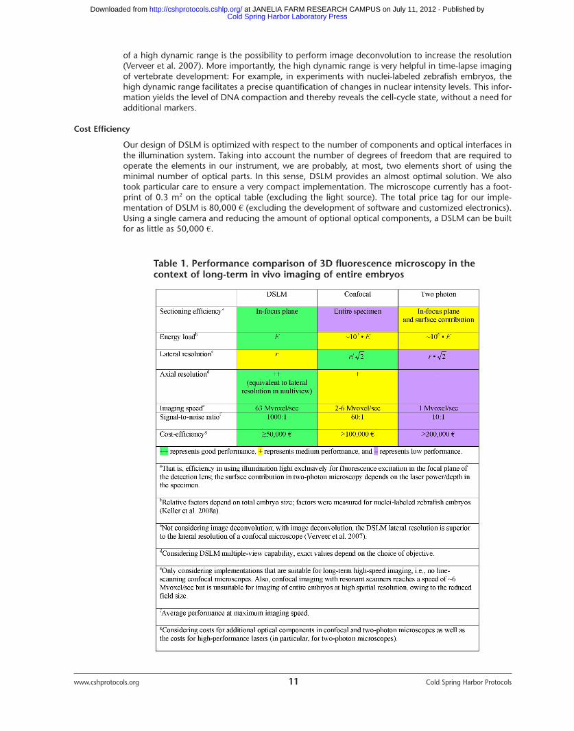
Table 1. Performance comparison of 3D fluorescence microscopy in thecontext of long-term in vivo imaging of entire embryos
Cold Spring Harbor Laboratory Press at JANELIA FARM RESEARCH CAMPUS on July 11, 2012 - Published by http://cshprotocols.cshlp.org/Downloaded from
Arnaout R, Ferrer T, Huisken J, Spitzer K, Stainier DY, Tristani-FirouziM, Chi NC. 2007. Zebrafish model for human long QT syndrome.Proc Natl Acad Sci 104: 11316–11321.
Denk W, Strickler JH, Webb WW. 1990. Two-photon laser scanningfluorescence microscopy. Science 248: 73–76.
Engelbrecht CJ, Stelzer EH. 2006. Resolution enhancement in a light-sheet-based microscope (SPIM). Opt Lett 31: 1477–1479.
Huisken J, Stainier DY. 2007. Even fluorescence excitation by multidirectional selective plane illumination microscopy (mSPIM).Opt Lett 32: 2608–2610.
Huisken J, Swoger J, Del Bene F, Wittbrodt J, Stelzer EH. 2004. Optical sectioning deep inside live embryos by selective plane
illumination microscopy. Science 305: 1007–1009.Keller PJ, Pampaloni F, Stelzer EH. 2006. Life sciences require the third
dimension. Curr Opin Cell Biol 18: 117–124.Keller PJ, Pampaloni F, Stelzer EH. 2007. Three-dimensional
preparation and imaging reveal intrinsic microtubule properties.Nat Methods 4: 843–846.
Keller PJ, Schmidt AD, Wittbrodt J, Stelzer EH. 2008a. Reconstructionof zebrafish early embryonic development by scanned light sheetmicroscopy. Science 322: 1065–1069.
Keller PJ, Pampaloni F, Lattanzi G, Stelzer EH. 2008b. Three-dimen-sional microtubule behavior in Xenopus egg extracts reveals fourdynamic states and state-dependent elastic properties. Biophys
www.cshprotocols.org 12 Cold Spring Harbor Protocols
CONCLUSIONS
DSLM is particularly well suited to address the issues encountered in in vivo imaging of large multi-cellular organisms. DSLM provides up to 50 times higher imaging speeds and a 10-100 times highersignal-to-noise ratio, while exposing the specimens to at least three orders of magnitude less lightenergy than confocal and two-photon fluorescence microscopes (Table 1; for color table, see doi:10.1101/pdb.top78 online at www.cshprotocols.org.).
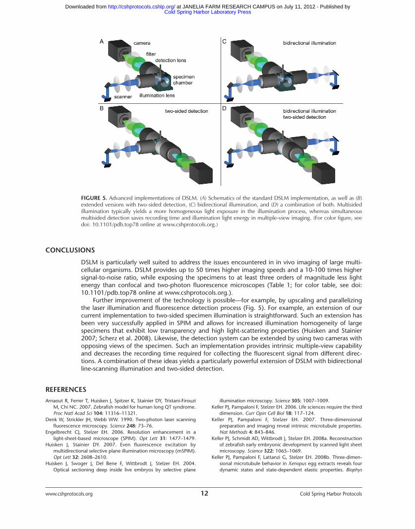
Further improvement of the technology is possible—for example, by upscaling and parallelizingthe laser illumination and fluorescence detection process (Fig. 5). For example, an extension of ourcurrent implementation to two-sided specimen illumination is straightforward. Such an extension hasbeen very successfully applied in SPIM and allows for increased illumination homogeneity of largespecimens that exhibit low transparency and high light-scattering properties (Huisken and Stainier2007; Scherz et al. 2008). Likewise, the detection system can be extended by using two cameras withopposing views of the specimen. Such an implementation provides intrinsic multiple-view capabilityand decreases the recording time required for collecting the fluorescent signal from different direc-tions. A combination of these ideas yields a particularly powerful extension of DSLM with bidirectionalline-scanning illumination and two-sided detection.
REFERENCES
FIGURE 5. Advanced implementations of DSLM. (A) Schematics of the standard DSLM implementation, as well as (B)extended versions with two-sided detection, (C) bidirectional illumination, and (D) a combination of both. Multisidedillumination typically yields a more homogeneous light exposure in the illumination process, whereas simultaneous multisided detection saves recording time and illumination light energy in multiple-view imaging. (For color figure, seedoi: 10.1101/pdb.top78 online at www.cshprotocols.org.)
Cold Spring Harbor Laboratory Press at JANELIA FARM RESEARCH CAMPUS on July 11, 2012 - Published by http://cshprotocols.cshlp.org/Downloaded from
J 95: 1474–1486.Kubitscheck U, Kuckmann O, Kues T, Peters R. 2000. Imaging
and tracking of single GFP molecules in solution. Biophys J 78:2170–2179.
Pawley J. 2006. Handbook of confocal microscopy. Springer, New York.Scherz PJ, Huisken J, Sahai-Hernandez P, Stainier DY. 2008. High-
speed imaging of developing heart valves reveals interplay ofmorphogenesis and function. Development 135: 1179–1187.
Siedentopf H, Zsigmondy R. 1903. Über Sichtbarmachung undGrößenbestimmung ultramikroskopischer Teilchen, mit beson-derer Anwendung auf Goldrubingläser. Ann Phys 315: 1–39.
Stelzer EHK. 1998. Contrast, resolution and the signal to noise ratioin fluorescence microscopy. J Microsc 1: 15–24.
Stelzer EHK, Hell SW, Lindek S, Stricker R, Pick R, Storz C, Ritter G,Salmon N. 1994. Nonlinear absorption extends confocal fluores-
cence microscopy into the ultra-violet regime and confines theillumination volume. Opt Commun 104: 223–228.
Swoger J, Verveer P, Greger K, Huisken J, Stelzer EHK. 2007. Multi-view image fusion improves resolution in three-dimensionalmicroscopy. Opt Express 15: 8029–8042.
Vermot J, Fraser SE, Liebling M. 2008. Fast fluorescence microscopyfor imaging the dynamics of embryonic development. HFSP J 2:143–155.
Verveer PJ, Swoger J, Pampaloni F, Greger K, Marcello M, Stelzer EH.2007. High-resolution three-dimensional imaging of large specimens with light-sheet-based microscopy. Nat Methods4: 311–313.
Voie AH, Burns DH, Spelman FA. 1993. Orthogonal-plane fluores-cence optical sectioning: Three-dimensional imaging of macro-scopic biological specimens. J Microsc 170: 229–236.
www.cshprotocols.org 13 Cold Spring Harbor Protocols
Cold Spring Harbor Laboratory Press at JANELIA FARM RESEARCH CAMPUS on July 11, 2012 - Published by http://cshprotocols.cshlp.org/Downloaded from