digital Power Monitor Installation And Operation · HPL110 Digital Power Monitor Installation and...
20
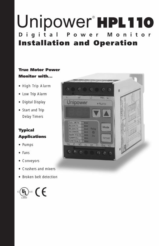
HPL110 Digital Power Monitor Installation and Operation True Motor Power Monitor with... • High Trip Alarm • Low Trip Alarm • Digital Display • Start and Trip Delay Timers Typical Applications • Pumps • Fans • Conveyors • Crushers and mixers • Broken belt detection Unipower Listed ®
Transcript of digital Power Monitor Installation And Operation · HPL110 Digital Power Monitor Installation and...
HPL110D i g i t a l P o w e r M o n i t o r
Installation and Operation
True Motor Power
Monitor with...
• High Trip Alarm
• Low Trip Alarm
• Digital Display
• Start and Trip
Delay Timers
Typical
Applications
• Pumps
• Fans
• Conveyors
• Crushers and mixers
• Broken belt detection
Unipower
Listed
®

▲
▲
2
Contents
1 System Overview 3
2 Functional Description 4
3 Typical Applications 7
4 System Configuration 8
5 Electrical Installation: 10
3-Phase Power Connection1-Phase Power ConnectionAlarm Relay StatesAlarm Integration Reset Function
6 Specifications: 13Technical SpecificationsDIP Switches
7 Mechanical Installation 14HPL110Current TransformerOptional Mounting Accessories and Enclosures
8 Programming 16
9 Troubleshooting 19
10 Set-Up Log Sheet 20
! WARNING: Dangerous voltages are present in motor control panels; INSTALLATION MUST BE CARRIED OUT BY QUALIFIED PERSONNEL.
! WARNING: Improper installation or programming can cause damage to the unit and/or result in ineffective protection and/or nuisance tripping.

System Overview
The Unipower HPL 110 advanced digital power monitor is a member of the Unipower family of “Intelligent Power-Control Units” designed for protection and control of motor driven mechanical systems.
The HPL 110 measures true power consumption of 3-phase AC motors (single phase versions also available) and displays consumption as a percentage of selected power range. Power consumption (kW) is calculated from the formula:
P = Ö3 x U x I x cos j
The display shows power in units of %kW which represent the percentage of full load power range for the unit.
Control functions comprise two independent and programmable trip functions:
Low Power Alarm - for example, to stop a pump in the event of dry-running, and
High Power Alarm - for example, to stop a feeder when blocked.
The alarm functions activate a single alarm relay which may be used to control the motorbeing monitored; i.e. to trip a shut-down in the event of either a high or low power alarm.
The HPL 110 may be configured to monitor any size motor either with the internal currenttransformer for applications up to 8A or with an external CT for applications above 8A.
The HPL 110 provides consistent sensitivity across the complete motor load range making itideal for low trip applications where amp meters are ineffective. In addition, the HPL 110measurement principle allows it to be used on non-sine shaped loads such as VariableFrequency Drives.
The digital design of the HPL 110 including 3-key programming, 3 digit display, Max/MinPeak Hold, Program Lock and Power Down Alarm Block functions make it very easy to use.
3
1

Functional Description
The Unipower HPL 110 may be used either for monitoring applications - to protectprocess equipment - or for control applications - to control secondary process functions.
Monitoring Example for Machinery ProtectionA typical Power vs. Time graph for the HPL 110 is shown in Figure 2.1 with the Y-axisshowing power P in units of %kW and the X-axis showing time.
At time 0, mains power is turned on, the HPL 110 unit is energized and the alarm relaychanges state to the “on” condition.
At time 1, the motor is turned on and the load immediately surges due to the startingcurrent inrush before settling to a steady value at time 4.5.
At time 8, this example shows power rising above the L1 Max. Limit which triggers analarm resulting in the motor being switched off at time 9.5.
A continuation is shown starting at time 20 where the motor load drops such that it falls below the L2 Min Limit at time 22. An alarm is again triggered after the delay timer expires resulting in the motor again being shut down at time 23.
0%
Max. LimitL1
100%
P (%)
Ts
t
Tr1
Power On
Relay On
5%
Motor On
0 1 2 3 4 5 6 7 8 9 2 0 2 1 2 2 2 3
P = f (t)
Min. LimitL2
Tr2
4
2
Figure 2.1

The HPL110 functions in these examples are as follows:
P - Power %kW: The display shows true power in units of % of full scale for the HPL 110 as installed.
Ts - Start Delay Timer: Ts is used to delay the start of active monitoring until after the start surge is completed.
The HPL 110 assumes that the motor is OFF when measured load - %kW - is below5% full scale. The Ts timer starts when the load reaches 5% and monitoring is disabled for the duration of the Ts period. Ts is programmable in the range 0.1 to 99.9 seconds.
On conclusion of the Ts period, monitoring becomes active.
If P drops below 5%, monitoring is immediately disabled and a new Ts period will start as soon as load again reaches 5%.
L1 - Max. Limit: Max. alarm limit programmable in the range 5% to 100% / OFF and used in conjunction with the Tr1 Reaction Timer. A Max. Limit alarm is tripped if P exceeds L1 for a period Tr1.
Tr1 - Reaction Timer: Used in conjunction with the L1 Max. Limit and programmable in the range 0.0 to 99.9 seconds. Tr1 is time for which the P must remain above the L1 Max. Limit before an alarm is declared. If P falls below the L1 during the Tr1 timer period, the timer is re-set to zero.
Note: if Tr1 is set to 0.0 seconds, actual reaction time will be one cycle or approx. 16 msec. at 60Hz and 20 msec. at 50Hz
L2 - Min. Limit: Min. alarm limit programmable in the range OFF / 5% to 100% and used in conjunction with the Tr2 Reaction Timer. A Min. Limit alarm is tripped when P remains below the L2 Min. Limit for a period of time Tr2.
Tr2 - Reaction Timer: Used in conjunction with the L2 Min. Limit and programmable in the range 0.0 to 99.9 seconds. Tr2 is time for which the P must remain below the L2 Min. Limit before an alarm is declared.
D - Max. Level: If the D up arrow key is depressed while the HPL 110 is in monitor mode, the display will show the maximum load - in %kW - experienced since the last Ts.
Ñ - Min. Level: If the — down arrow key is depressed while the HPL 110 is in monitor mode, the display will show the minimum load - in %kW - experienced since the last Ts.
5

Control ExampleWhile monitoring for machinery protection is the primary application for the HPL 110, it is also suitable for simple two-point control regulation applications by using the Hysteresisfunction included in the unit.
A possible control example might be where the HPL 110 is monitoring the power consumed to mix a slurry and the relay output is used to add liquid if the slurry becomestoo viscous.
This is shown graphically in Figure 2.2. Power surges when the motor is switched on and the Ts function inhibits monitoring until the motor settles at time 2.5.
Once Ts is completed, the high power alarm becomes active and a hysteresis band (programmable) is shown under this alarm level. At time 5, the mixing power rises above the L1 Max. Limit and, after the Tr1 trip delay times out, the alarm is activatedand the relay switches.
In this example, the relay controls the addition of liquid to the slurry and the power gradually drops as liquid is added until at time 7, it has fallen below the hysteresis band for the L1 Max. Limit. At this point, the alarm relay is automatically reset and the addition of liquid is stopped.
Typical applications include the continuous control of mixing, crushing and grindingprocesses. Hysteresis is also available on the L2 Min. limit in the same manner (not shown).
Max. LimitL1
100%
P (%)
Ts
t
Tr1
Power On
Relay On
0 1 2 3 4 5 6 7
P = f (t)
5%
6 Figure 2.2

Typical Applications
Centrifugal PumpsThese “positive pressure” pumps have a power curve which is proportional to flow rate.Power monitoring using the HPL 110, therefore, is very effective at ensuring the pump isrunning within the design minimum and maximum flow limits.
This is particularly true of seal-less pumps where dry-running can quickly result in damageor failure of the pump and containment system.
These situations are very effectively detected by the HPL 110 as “low power” alarms(being a true power monitor, the HPL 110 is far more effective at detecting under-powersituations than a current sensing relay).
Positive Displacement PumpsIn the case of positive displacement pumps, flow rate is constant but excessive outletrestriction results in high pressure and high power. The HPL 110 provides a simple, non-intrusive monitoring function which can be effectively used to protect against dead-heading.
Again, dry-running is detrimental to the pump and results in a low power condition which is also effectively monitored for with the HPL 110.
Belt BreakageThe HPL 110 can be used to immediately detect a low power conditions resulting fromtransmission chain or belt breakage and is far more sensitive to such "low power" conditions than a simple current sensor.
The HPL 110 helps avoid the damage which is easily generated when part of a productionline is malfunctioning.
Feeder BlockageThe HPL 110 can be used to immediately generate a max. kW alarm when a feeder mechanism is jammed or overloaded. Such applications would include belt or screw feeders, conveyors, etc. In many cases, the HPL 110 can replace mechanical shear pinsand are easier to set.
Many Other Applications exist including: Fans, Mixers, Crushers, Grinders, etc.
7
3

System Configuration
The Unipower HPL 110 measures voltage in all three legs of the 3-phase supply (or oneleg and neutral for single phase versions) and current in one leg. The HPL 110 has aninternal current transformer with a measurement range of 8 Amps.
In configuring the HPL 110 for a particular application, the voltage rating of the unit mustmatch the mains supply being used and the effective current measured by the unit mustbe within its internal 8 Amp capacity.
4.1 VOLTAGE MATCHING:From Table 4.1, ensure that the rated voltage for the HPL 110 unit matches the mainsvoltage being used.
For single phase applications, an isolation transformer must always be used with a secondary voltage of 24V.
Note: The display full scale for the HPL 110 is based on the nominal voltage of the unit;e.g. when using a nominal 220V unit at 208V, the display range will read 95% at full load(208/220 in %).
4.2 CURRENT MATCHING:From the motor name plate, note the full load current in Amps. If full load amperage for the motor is 8 amps or less, an external current transformer is not required.
If the full load current is greater than 8 amps, then an external N/1 or N/5 current transformer must be used.
Refer to Table 4.2 for the appropriate selection of current transformer and current rangesetting for the HPL 110.
The HF3A current transformers specified in this table are low voltage, through-primarydevices offered as accessories for the HPL 110 product line; equivalent devices from other manufacturers may be substituted at user’s discretion.
8
Catalog Number Phase Use for 50/60 Hz Mains Voltages
HPL110/220 3-Phase 208/220/230/240 VAC
HPL110/380 3-Phase 380/415 VAC
HPL110/460 3-Phase 460/480 VAC
HPL110/575 3-Phase 575/600 VAC
HPL110/S24 1-Phase 110/120 and 208/220/230/240 VAC
Figure 4.1
4

Note: The two ranges given for full load ratings of 15 and 25 Amps require two primarywraps of the current transformer whereas all other ranges require a single through primary.
Figure 4.3 shows the HF3A current transformers with a single through primary hook-up and with two primary wraps. When taking multiple primary wraps on the HF3A currenttransformers, ensure that the wraps are wound to the sides and not across the top or bottom of the current transformer.
9
Figure 4.2
Full Load Current Ratio Primary HPL110 Range Effective RangeAmps Transformer Primary : Secondary Turns Setting Amps
1 Internal 1 : 1 1 1 1
3 Internal 1 : 1 1 3 3
5 Internal 1 : 1 1 5 5
8 Internal 1 : 1 1 8 8
10 HF3A,050/5 50 : 5 1 1 10
15 HF3A,050/5 50 : 5 2 3 15
25 HF3A,050/5 50 : 5 2 5 25
30 HF3A,050/5 50 : 5 1 3 30
50 HF3A,050/5 50 : 5 1 5 50
75 HF3A,075/5 75 : 5 1 5 75
100 HF3A,100/5 100 : 5 1 5 100
150 HF3A,150/5 150 : 5 1 5 150
Figure 4.3

Installation - Electrical
5.1 3-PHASE HOOK-UPThe HPL 110 should be connected directly in front of the motor starter unit and down-stream of the motor fuses and/or isolation breaker as shown in Figure 5.1.
An external current transformer with a secondary rating of 1 or 5 amps must be used if the rated full load motor current is in excess of 8 amps. Figure 5.1 shows correct installation using the internal current transformer (<8A), and using an external currenttransformer (>8A).
For correct readings, the current measurement must always be made on the L3 leg of the3-phase supply. The direction of the current measurement, however, is not important.
Power-Down Alarm Blocking: When the motor is turned off, power drops to zero anda Min. Limit Alarm will be triggered if L2 is active. Figure 5.1 shows an auxiliary normallyclosed contact on the motor starter being used to short S2 to Gnd when the motor is off.This activates the S2 inhibit function which inhibits alarm functions and prevents a Min.Limit alarm on power down.
An alternative method of achieving the same result is available using the Min. Alarm Block function explained in Section 8.8; the S2 Inhibit solution described above is preferred and safer.
Soft Starts and Frequency Inverters: Driven by a frequency inverter, the HPL 110 connections must be made directly in front of these devices.
10
5
L1L2L3
M3~ In < 8 Amp.
Example internal converter
Only if min. limit used
K
1110
NC
MotorFuses
MotorFuses
Aut. ResetExt. Reset
Aut. ResetExt. Reset
1 L1
5 L3
7 k8 l S2 16
Gnd 15S1 14X2 13X1 12
9C
NO
HPL110
1 L1
5 L3
7 k8 l S2 16
Gnd 15S1 14X2 13X1 12
9C
NO
M3~
In > 8 Amp.
Only if min. limit used
NC
1110
Example external converter
3 L2
K
3 L2
S1
S2
P1
P2
HPL110
Figure 5.1

5.2 SINGLE PHASE HOOK-UPFigure 5.2 shows correct connection for single phase mains units. The single phase versionof the HPL 110 requires a 24V secondary isolation transformer (supplied) with the L2 -Neutral side of the secondary grounded.
5.3 ALARM RELAY STATESFigure 5.3 shows the states for the alarm relay. The relay is energized when the HPL 110 ispowered and is de-energized when an alarm state exists - fail safe operation. The Relay LEDon the front panel is illuminated when the Relay is energized; this Relay LED, therefore, is onduring normal operation and is switched off when an alarm occurs.
11
Power Off On On
Alarm Condition No No Yes
Relay LED Off On Off
Limit LED Off Off Flashing
NC 9
COM 10
NO 11
Figure 5.3
M1~
24V SecondaryIsolation
Transformer
HPL1101 L1
3 L2
5 L3
7 k
8 l S2 16Gnd 15S1 14X2 13X1 12
9C
NO
NC
1110
L1
L2
K
Only if min. limit used
MotorFuses
Figure 5.2
Note: The HPL110 has a single alarm relay which is tripped by both a max. and/or a min. limit alarm.

5.4 ALARM INTEGRATIONIn order for the HPL 110 to stop the motor in the event of an alarm, the alarm relay (terminals 9, 10 and 11) must be integrated into the motor starter circuit such that itduplicates the effect of activating the STOP button.
One possibility is shown in Figure 5.4 where the NC relay contacts (terminals 9 and 10)are connected in series with the STOP button. When an alarm occurs, Terminals 9 and 10 change from closed to open which is equivalent to pressing the STOP button.
If an Alarm enunciation light is required, it can be connected between Terminal 11 andneutral to illuminate when an alarm state exists.
5.5 RESET FUNCTIONThe HPL 110 may be reset by any one of three methods:
Manual Reset: Depress the Reset key on the front panel.
Remote Reset: By wiring an Auxiliary reset button across contacts S1 to GND (pins 14 to 15) on the HPL 110, a remote reset may be achieved.
Automatic Reset: By wiring a jumper across contacts S1 to GND, the HPL 110 operatesin automatic reset mode with the Hysteresis function active; this is typically only used for two-point control applications and not for protection applications.
12
L1
L2
L3M
START
15 16
STOP
HPL110
1 L1
5 L3
7 k8 l S2 16
Gnd 15S1 14X2 13X1 12
9C
NO
NC
1110
3 L2
Figure 5.4

Listing:
6.2 DIP SWITCHESThe front cover plate is easily removed with a small screwdriver—snap-out.
13
Specifications
6.1. TECHNICAL SPECIFICATIONS
6
Figure 6 .1
ElectricalVoltage Range: See unit for rangeStandard ranges—3 x 220, 380, 460, and 575VAlso available— 1 x 24V for 110/220V single phaseCurrent Range:Internal - max. 8AExternal - N/1 or N/5 converterCos j Range: 0 ® 1Frequency Range: 45 ® 65 HzConsumption:Supply voltage = measurement voltage, 2 VARelay Output: 250VAC/5Amp
MechanicalHousing:Polycarbonate (30%GFR),UL94V-1(house)Polycarbonate, UP94V-2 (connector + front)Mounting: Snap on for 35mm DIN railmounting or panel mountingProtection Class: IP40 (house), IP20 (connector)Terminals: 12 AWG max., 20AOperating Temperature Range:+5 ® +122
0F (-15 ® +50
0C)
Weight: ~1lb (0.5 kg)Dimensions:D 3.0” x B 2.1” x H 4.3”(D 75 x B 56 x H 110 mm)
Listed
Functions:DIP Sw. 1 “OFF” = Programming Enabled
DIP Sw. 1 “ON” = Programming Disabled(Protected)
DIP Sw. 2 “OFF” = Alarms Normal
DIP Sw. 2 “ON” = Special Min. Alarm Block Function Enabled, see 8.8, page 18
CE mark to EN50081-1, 50082-2, 61010-1UL certified to UL508 (USA) and C22.2 No.14-M91 (Canada) standards for Industrial Control Equipment

Installation - Mechanical
HPL110 Module
The HPL110 unit is typically mounted inside the motor starter enclosure or existing electrical cabinet. The unit is configured to snap directly onto 35mm DIN rail or may be attached to a panel using 2 x M4 or #8 screws.The HPL110 housing is not sealed and must be protected inside an appropriate environmental enclosure. The terminal connections are rated for 12 AWG (4mm2) wires max.
Current Transformers
The optional HF3Axxx/x series current
transformers may be mounted either
directly to standard 35mm DIN rail,
as shown on Page 9, using
accessory 741B0231—not included—
or screwed directly to a panel using
two M5 or #10 cap screws with accessory
741B0230/6—not included—as shown in Fig. 7.2
Rail Mounting Kit - UPR.14K50
Optional installation kit for the HPL110 comprises a section of 35mm DIN rail, a set of terminal blocks for through wiring of mains supply and a wiring harness to complete connection to HPL110. Rail space is provided for mounting both HPL110 unit and HF3A current transformer. Terminal blocks accommodate 8 AWG (10mm2) max. wires, 50 Amp.
14
7
55
170
75
110
35
37
61
56
60
54
40
Æ17
40
2852
27
Figure 7.3
Figure 7.2
Figure 7.1

15
NEMA4X Enclosure Kit - UPE.14CH50
Optional enclosure kit for HPL110 which provides a stand-alone mounting solution for applications up to 50 Amps. The kit comprises a NEMA4X enclosure with clear hinged door. The UPR.14K50 rail mounting kit detailed above is pre-installed inside. Mounting is either with 4 x M6 SHCS’s through the captive corner mounting holes or 4 x M6 SHCS’s using the optional external mounting feet, accessory MB10674 - not included.Mains power lines must be run into and out of the
enclosure using standard practice, fittings not included.
NEMA4X MINI-Enclosure Kit - UPE.14MINI
Compact, sealed mounting solution for HPL110. Kit comprises a NEMA4X enclosure with clear, screw-down door into which the HPL110 is mounted (screws included). A 3’ length 12-conductor cable is installed and prepared for hook-up. PG9 compression feed-through fittings are also included for routing the cable into an existing enclosure. External current transformer, if used, must be installed in the motor starter enclosure.An external RESET button is recommended (not included). Mounting is either with 4 x M4 SHCS’s through the captive corner mounting holes or 2 x M6 SHCS’s using the optional external mounting feet (148 lengthwise pattern - shown - or 98 widthwise pattern - not shown).
125
75
125
148
3’ Cable
107
57
HPL
7
Figure 7.5
188
164
130
204
1647
Figure 7.4

Programming
The Modes and Programming ranges for the HPL 110 are given in the Function Table below:
The HPL 110 is programmed using only three keys - MODE, D, Ñ. The MODE key is used toselect the variable to be programmed and the values are adjusted using the D, Ñ keys. Thedefault state for the HPL 110 on power up is kW[%] mode. If any key is continuouslydepressed, its action is repeated. When no key has been depressed for about 5 seconds, the mode reverts to kW[%] mode.
The HPL110 is programmed in the following sequence:
8.1 CURRENT RANGEDepress the MODE key to select Current Range [A] mode. From Table 4.2, find the correctCurrent Range value for the unit as installed and enter this value using the D, Ñ keys.
8.2 CHOOSING LIMITSThe HPL 110 may be programmed while running and it is useful to observe normal conditions in order to set the remaining parameters - Ts, L1, Tr1, L2 and Tr2.
To run the HPL 110 before the limits have been set, first de-activate the high and low alarmsby programming the L1 Max Limit to 101% and the L2 Min Limit to 0%. When a limit is de-activated, “OFF” is written in the display.
Then start the motor and:- note time delay between pressing start button and stable display reading,- load the system to max. normal operating load and press the D key to note the max.
allowable %kW value, - load the system to min. normal operating load and press the Ñ key to note the min.
allowable %kW value.
16
8
Mode Function Variable ▼ ▲ Display Default
Power=kW(%) kW display - Min.Peak Max.Peak kW (%) -
Max. Limit Max.kW Limit 5-100%/off Decrease Increase Off/Max.Limit (%) 80%
Min.Limit (%) Min.kW Limit Off/5-100% Decrease Increase Off/Min.Limit (%) 20%
Start Timer(S) Start Timer 0.1-99.9 Sec. Decrease Increase Ts (Sec.) 2.0 Sec.
Reaction Timer(S) Max.Alarm Delay 0.0-99.9 Sec Decrease Increase Max. Tr (Sec.) 0.1 Sec.
Reaction Timer(S) Min.Alarm Delay 0.0-99.9 Sec Decrease Increase Min. Tr (Sec.) 0.1 Sec.
Hysteresis(%) 2 points regulation 2-50% Decrease Increase Hysteresis (%) 10%.
Current Range(A) Current Range 1,3,5,8 Amp. Decrease Increase 1,3,5,8 5 Amp.

17
Use the values noted to set the remaining program parameters as described below.
8.3 TS: START TIMERThe Ts Start Delay Timer is used to inhibit monitoring during the motor start-up surge. To determine the appropriate value for Ts, start the motor and observe how long - seconds - it takes for the HPL 110 kW[%] display value to stabilize.
Depress the MODE key to select Start Timer [s] and then use the D, Ñ keys to adjust Ts value to a duration which is slightly longer than the settling time observed.
Since monitoring is inhibited while Ts is active, always try to set this parameter as low as possible without generating false alarms.
8.4 MAX. LIMIT TRIP POINTUsing the Peak Detect function, run the system at its minimum load condition andobserve the max. normal reading by depressing the Ñ key.
Set the Max. Limit value a few units higher than this value by depressing the MODE key to select Max. Limit [%] and then use the D, Ñ keys to adjust.
8.5 MIN. LIMIT TRIP POINTAgain using the Peak Detect function, run the system at its minimum load condition andobserve the min. normal reading by depressing the Ñ key.
Set the Min. Limit value a few units lower than this value by depressing the MODE key to select Min. Limit [%] and then use the D, Ñ keys to adjust.
8.6 REACTION TIMER SETTINGThe HPL 110 has independent Reaction Timers for both the Max. Limit alarm and Min.Limit alarm which delay the alarm response when running outside the programmed limits.Their purpose is to reduce false alarms due to normal process fluctuations.
Both Reaction Timers should be set to the lowest value which does not result in false tripping. The default values of 0.1 sec. will be good starting points for applications requir-ing rapid response, e.g. blockage detection on conveyors. For process applications suchas pumps and mixing, longer Tr values - 1 to 2 sec. - will probably be more appropriate.
To set Reaction Time, depress the MODE key to select Reaction Timer [s] and Max. Limit[%] and then use the D, Ñ keys to adjust for Max. Limit Reaction Time.
Depress the MODE key again to select Reaction Timer [s] and Min. Limit [%] and then usethe D, Ñ keys to adjust for Min. Limit Reaction Time.

8.7 RESPONSE TESTA system response test should now be carried out to ensure that the HPL 110 correctlystops the motor in the event of an alarm. To do this, run the system under normal conditions – no alarm should occur – and then depress the MODE key to select Max.Alarm [%] mode.
While in Max. Alarm [%] mode, use the D, Ñ keys to adjust the alarm limit to a valuewhich is lower than normal running.
Use the MODE key to return to Power = kW [%] mode and wait. The Reaction TimerLED should illuminate and, once the reaction time has expired, a Max. Limit alarmshould be triggered.
When the Max. Limit alarm triggers, the motor should stop.
8.8 DIP SWITCH FUNCTIONSProgram Lock: Once the HPL 110 has been programmed, accidental changes may beprevented by turning the PROGRAM LOCK function on. To do this, switch DIP Switch 1to the “ON” position, see section 6.2 for access. When Program Lock is "ON", all setting values may be viewed but not changed. The Reset button, however, remainsfunctional.
Power-Down Alarm Block: If using the HPL 110 with an active L2 Min. Alarm, thenit is advised to use the S2-GND inhibit function described in Section 5.1 to prevent falseMin. Alarms when the motor is switched off.
If this is impractical, then the Power-Down Alarm Block function will prevent a minalarm from being declared if measured power falls below 5% of full load within the Tr2 trip delay value.
To select Power-Down Block function, set DIP Switch 2 to the “ON” position.
8.9 CONVERTING %KW TO ENGINEERING UNITS.If it is necessary to set alarm limits in units of HP or kW or Torque, please refer to yoursupplier or directly to WEN Technology for assistance. All set-up information on theSet-Up Log Sheet - see back cover - will be required with the Max. and Min. Limit values required given in the desired units.
18
19
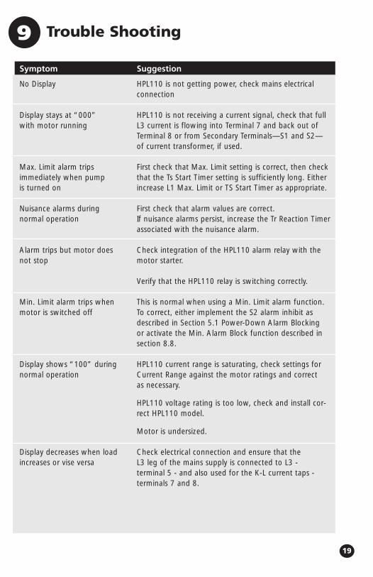
Trouble Shooting9
Symptom
No Display
Display stays at “000”with motor running
Max. Limit alarm trips immediately when pumpis turned on
Nuisance alarms during normal operation
Alarm trips but motor doesnot stop
Min. Limit alarm trips whenmotor is switched off
Display shows “100” duringnormal operation
Display decreases when loadincreases or vise versa
Suggestion
HPL110 is not getting power, check mains electrical connection
HPL110 is not receiving a current signal, check that full L3 current is flowing into Terminal 7 and back out ofTerminal 8 or from Secondary Terminals—S1 and S2—of current transformer, if used.
First check that Max. Limit setting is correct, then checkthat the Ts Start Timer setting is sufficiently long. Eitherincrease L1 Max. Limit or TS Start Timer as appropriate.
First check that alarm values are correct.If nuisance alarms persist, increase the Tr Reaction Timerassociated with the nuisance alarm.
Check integration of the HPL110 alarm relay with themotor starter.
Verify that the HPL110 relay is switching correctly.
This is normal when using a Min. Limit alarm function.To correct, either implement the S2 alarm inhibit asdescribed in Section 5.1 Power-Down Alarm Blockingor activate the Min. Alarm Block function described insection 8.8.
HPL110 current range is saturating, check settings forCurrent Range against the motor ratings and correct as necessary.
HPL110 voltage rating is too low, check and install cor-rect HPL110 model.
Motor is undersized.
Check electrical connection and ensure that the L3 leg of the mains supply is connected to L3 - terminal 5 - and also used for the K-L current taps - terminals 7 and 8.

Set-Up Log Sheet
Application
Description
Motor
Model
Full Load Power ❏ kW ❏ HP
Rated Full Load Current A
Rated Mains Voltage V
Mains Frequency ❏ 60 Hz ❏ 50 Hz
Phase ❏ 3-Phase ❏ 1-Phase
Rated Efficiency %
UnipowerHPL110 Model HPL110/xxx ❏ 220 ❏ 380 ❏ 460 ❏ 575 ❏ S24
Current Transformer ❏ None ❏ 50/5 ❏ 75/5 ❏ 100/5 ❏ 150/5
Turns through CT ❏ 1x ❏ 2x
Program
Current Range (A) ❏ 1 ❏ 3 ❏ 5 ❏ 8
Start Time (S) S
Max. Limit (%) %
Reaction Timer (S) - Max S
Min. Limit (%) %
Reaction Timer (S) - Min S
Program Lock ❏ On ❏ Off
Min. Alarm Block ❏ On ❏ Off
10
®
8411 Garvey Drive / Suite 117Raleigh, North Carolina 27616(919) 954-1004 / Fax (919) 954-1009www.wentec.com
Software Version: 3.0Document Number: WT99H001
© 1999 Wen Technology, Inc., Raleigh, NC USA