Digital Phosphor Oscilloscopes - DPO7000 Series · moved among all your DPO/DSA70000B, MSO70000,...
20
Digital Phosphor Oscilloscopes DPO7000 Series Data Sheet Features & Benefits 3.5 GHz Bandwidth Model for Serial and Digital Applications 2.5 GHz, 1 GHz, and 500 MHz Bandwidth Models for All Applications Up to 40 GS/s Real-time Sample Rate on One Channel and up to 10 GS/s on All Four Channels Up to 500 Megasamples Record Length with MultiView Zoom™ Feature for Quick Navigation >250,000 wfms/s Maximum Waveform Capture Rate Up to 310,000 Waveforms per Second with FastFrame™ Segmented Memory Acquisition Mode User-selectable Bandwidth Limit Filters for Better Low-frequency Measurement Accuracy MyScope ® Custom Windows and Right Mouse Click Menus for Exceptional Efficiency Event Search and Mark to Find Specific Events in the Entire Waveform Pinpoint ® Triggering provides the Most Flexible and Highest Performance Triggering, with Over 1400 Combinations to Address Virtually Any Triggering Situation. 12.1” XGA Display with Touch Screen Communications Mask Testing Clock Recovery from Serial Data Streams 64-bit NRZ Serial Pattern Trigger for Isolation of Pattern-dependent Effects up to 1.25 Gb/s Low-speed Serial Protocol Triggering and Decode (I 2 C, SPI, RS-232, CAN, LIN, and FlexRay) Technology-specific Software Solutions provide Built-in Domain Expertise for MIPI ® D-PHY, Ethernet, USB 2.0 Compliance Testing, Jitter, Timing, Eye Diagram, Power, DDR Memory Bus Analysis, CAN, LIN, and FlexRay Network Design OpenChoice ® Software with Microsoft Windows XP OS enables Built-in Networking and Extended Analysis Applications Signal Integrity, Jitter, and Timing Analysis Verification, Debug, and Characterization of Sophisticated Designs Debugging and Compliance Testing of Serial Data Streams for Telecom and Datacom Industry Standards Low-speed Serial Bus Design (I 2 C, SPI, RS-232, CAN, LIN, and FlexRay) Investigation of Transient Phenomena Power Measurements and Analysis Spectral Analysis Advanced Test Equipment Rentals www.atecorp.com 800-404-ATEC (2832) ® E s t a blishe d 1 9 8 1
Transcript of Digital Phosphor Oscilloscopes - DPO7000 Series · moved among all your DPO/DSA70000B, MSO70000,...

Digital Phosphor OscilloscopesDPO7000 Series Data Sheet
Features & Benefits3.5 GHz Bandwidth Model for Serial and Digital Applications
2.5 GHz, 1 GHz, and 500 MHz Bandwidth Models for All Applications
Up to 40 GS/s Real-time Sample Rate on One Channel and up to10 GS/s on All Four Channels
Up to 500 Megasamples Record Length with MultiView Zoom™ Featurefor Quick Navigation
>250,000 wfms/s Maximum Waveform Capture Rate
Up to 310,000 Waveforms per Second with FastFrame™ SegmentedMemory Acquisition Mode
User-selectable Bandwidth Limit Filters for Better Low-frequencyMeasurement Accuracy
MyScope® Custom Windows and Right Mouse Click Menus forExceptional Efficiency
Event Search and Mark to Find Specific Events in the Entire Waveform
Pinpoint® Triggering provides the Most Flexible and HighestPerformance Triggering, with Over 1400 Combinations to AddressVirtually Any Triggering Situation.
12.1” XGA Display with Touch Screen
Communications Mask Testing
Clock Recovery from Serial Data Streams
64-bit NRZ Serial Pattern Trigger for Isolation of Pattern-dependentEffects up to 1.25 Gb/s
Low-speed Serial Protocol Triggering and Decode (I2C, SPI, RS-232,CAN, LIN, and FlexRay)
Technology-specific Software Solutions provide Built-in DomainExpertise for MIPI® D-PHY, Ethernet, USB 2.0 Compliance Testing, Jitter,Timing, Eye Diagram, Power, DDR Memory Bus Analysis, CAN, LIN, andFlexRay Network Design
OpenChoice® Software with Microsoft Windows XP OS enables Built-inNetworking and Extended Analysis
ApplicationsSignal Integrity, Jitter, and Timing Analysis
Verification, Debug, and Characterization of Sophisticated Designs
Debugging and Compliance Testing of Serial Data Streams for Telecomand Datacom Industry Standards
Low-speed Serial Bus Design (I2C, SPI, RS-232, CAN, LIN, andFlexRay)
Investigation of Transient Phenomena
Power Measurements and Analysis
Spectral Analysis
Advanced Test Equipment Rentalswww.atecorp.com 800-404-ATEC (2832)
®
Established 1981

Data Sheet
Unmatched Performance for Greater InsightInto Your Design to Get Your Work DoneFasterThe DPO7000 Series are the new generation of real-time digital phosphoroscilloscopes and are the industry’s best solution to the challenging signalintegrity issues faced by designers verifying, characterizing, debugging, andtesting sophisticated electronic designs.
The family features exceptional performance in signal acquisition andanalysis, operational simplicity, and unmatched debugging tools toaccelerate your day-to-day tasks. The largest screen in the industry andthe intuitive user interface provide easy access to the maximum amount ofinformation.
Unmatched Acquisition Performance
Signal Fidelity of Tektronix Oscilloscopes EnsuresConfidence in Your Measurement Results
High sample rate on all models, on all channels, to capture more signaldetails (transients, imperfections, fast edges)
40 GS/s on one channel on the 2.5 GHz and 3.5 GHz modelsOption 2SR to double the maximum real-time sample rate for the1 GHz model
High bandwidth up to 3.5 GHz, matched across 2, 3, or 4 channelsand enabled by Tektronix proprietary DSP enhancement. Theuser-selectable DSP filter on each channel provides magnitude andphase correction plus extension to 3.5 GHz for more accurate signalfidelity for complex measurements. The DSP filter on each channel canalso be switched off to take advantage of true 2.5 GHz analog bandwidthfor applications needing the highest available raw data capture.
The DPO7000 Series oscilloscopes include as a standard feature aseries of user-selectable bandwidth limit filters. These filters preservethe instrument’s bandwidth roll-off characteristics, flatness, and phaselinearity within the new frequency range, thereby reducing the effects ofout-of-band noise on measurements. Now, designers can purchase oneinstrument for their highest bandwidth needs and easily optimize it tohandle lower-frequency measurements as well.
Very low jitter noise floor and vertical accuracy for very accuratemeasurements
Long acquisition to provide more resolution and longer time sequenceStandard 10 million data points per channel on the DPO7000 SeriesOptional up to 500 million total data points on 2.5 GHz and 3.5 GHzmodelsOptional up to 250 million total data points on the 500 MHz and 1 GHzmodelsEasily manage this deep record length, provide detailed comparisonand analysis of multiple waveform segments with the MultiViewZoom™ feature. Automatically scroll through deep records visually, orcreate a math expression to instantly highlight differences
Highest-performance probing solutions for differential and single-endedvoltage signals as well as current measurement, because accuratedesign verification depends on high-bandwidth access to critical signalsand high-fidelity signal capture
User-selectable bandwidth limiting choices.
Zoom in on four areas of interest simultaneously to compare them.
Unmatched Versatility
Get the Most of Your Oscilloscope by Fully Controllingits Waveform Acquisition and Display ParametersYou have the choice of three horizontal time base modes of operation. If youare simply doing signal exploration and want to interact with a lively signal,you will use the Automatic or interactive default mode that provides you withthe liveliest display update rate. If you want a precise measurement andthe highest real-time sample rate that will give you the most measurementaccuracy, then the Constant Sample Rate mode is for you. It will maintainthe highest sample rate and provide the best real-time resolution. The lastmode is called the Manual mode because it ensures direct and independentcontrol of the sample rate and record length.
With the MyScope® Feature, Create Your Own ControlWindows with Only the Controls, Features, andCapabilities that You Care AboutEasily create your own personalized "toolbox" of oscilloscope featuresin a matter of minutes using a simple, visual, drag-and-drop process.
2 www.tektronix.com

Digital Phosphor Oscilloscopes — DPO7000 Series
Tektronix active probes achieve high-speed signal acquisition and measurement fidelity.
Once created, these custom control windows are easily accessed througha dedicated MyScope button and menu selection on the oscilloscopebutton/menu bar, just like any other control window. You can make anunlimited number of custom control windows, enabling each person whouses the oscilloscope in a shared environment to have their own uniquecontrol window. MyScope control windows will benefit all oscilloscopeusers, eliminating the ramp-up time that many face when returning to the labafter not using an oscilloscope for a while, and enables the power user tobe far more efficient. Everything you need is found in one control windowrather than having to constantly navigate through menu after menu to repeatsimilar tasks.
3 modes of operation of the horizontal time base.
Drag and drop menu items of interest to create the MyScope control window.
www.tektronix.com 3

Data Sheet
Capture data into Microsoft Excel using the unique Excel toolbar, and create customreports using the Word toolbar.
With OpenChoice® Software, Customize Your Test andMeasurement Systemwith Familiar Analysis ToolsThe analysis and networking features of OpenChoice software add flexibilityto Windows XP Tektronix oscilloscopes: The Windows XP Remote Desktopfunctionality enables remote monitoring of the instrument over the internet.Using the fast embedded bus, waveform data can be moved directly fromacquisition to analysis applications on the Windows desktop at much fasterspeeds than conventional GPIB transfers. Implementation by Tektronixof industry-standard protocols, such as TekVISA™ interface and ActiveXcontrols, are included for using and enhancing Windows applicationsfor data analysis and documentation. Support for the DPO7000 Seriesis also available with NI LabVIEW SignalExpress™ Tektronix Edition.IVI-COM instrument drivers are included to enable easy communicationwith the oscilloscope using GPIB, serial data, and LAN connections fromprograms running on the instrument or an external PC. Or, use the SoftwareDeveloper’s Kit (SDK) to help create custom software to automate multistepprocesses in waveform collection and analysis with Visual BASIC, C, C++,MATLAB, LabVIEW, LabWindows/CVI, and other common ApplicationDevelopment Environments (ADE). Integration of the oscilloscope withexternal PCs and non-Windows hosts is also supported by the DPO7000Series software solutions. In addition, the OpenChoice architectureprovides a comprehensive software infrastructure for faster, more versatileoperations. Data transfer programs, such as the Excel or Word toolbar,are used to simplify analysis and documentation on the Windows desktopor on an external PC.
Maximize the probability of capturing elusive glitches and other infrequent events withFastAcq acquisition mode.
Accelerate the Debug of Complex ElectricalDesignsFastAcq Acquisition Mode Expedites Debugging byClearly Showing ImperfectionsMore than just color grading, FastAcq enabled by Tektronix proprietaryDPX® acquisition technology captures signals up to more than 250,000waveforms per second on all 4 channels simultaneously, dramaticallyincreasing the probability of discovering infrequent fault events. And with asimple turn of the intensity knob you can clearly see “a world others don’tsee,” because frequency of occurrence is color coded. Some oscilloscopevendors claim high waveform capture rates for short bursts of time, but onlythe DPO7000 Series, enabled by DPX technology, can deliver these fastwaveform capture rates on a sustained basis – saving minutes, hours, oreven days by quickly revealing the nature of faults so sophisticated triggermodes can be applied to isolate them.
4 www.tektronix.com

Digital Phosphor Oscilloscopes — DPO7000 Series
Isolate glitches down to 200 ps wide.
Isolate Setup and Hold violations down to 360 ps.
The Ability to Trigger an Oscilloscope on Events ofInterest is Paramount in Complex Signal Debug andValidationWhether you’re trying to find a system error or need to isolate a sectionof a complex signal for further analysis, like a DDR Read or Write burst,Tektronix Pinpoint® triggering provides the solution. The Pinpoint triggersystem uses Silicon Germanium (SiGe) technology to provide triggersensitivity of up to the bandwidth of the instrument, and allows selectionof most trigger types on both A and B trigger circuits. It can capture verynarrow glitches with very little trigger jitter. Other trigger systems offer
Easily trigger on a specific I2C address.
multiple trigger types only on a single event (A event), with delayed trigger(B event) selection limited to edge-type triggering and often do not provide away to reset the trigger sequence if the B event doesn’t occur. But Pinpointtriggering provides a full suite of advance trigger types on both A and Btriggers with Reset triggering to begin the trigger sequence again after aspecified time, state, or transition so that even events in the most complexsignals can be captured. Other oscilloscopes typically offer less than 20trigger combinations; Pinpoint triggering offers over 1400 combinations,all at full performance.With Enhanced Triggering, you can choose to compensate for the differencein time there is between the trigger path and the display path and eliminatevirtually any trigger jitter at the trigger point. In this mode, the trigger pointcan be used as a measurement reference.
Trigger on the Most Relevant Bit Sequence of theIndustry-standard Serial BusI2C (Inter-Integrated Circuit) triggering is a standard feature and includesStart Condition, Missing Acknowledge, Restart, Data Read, Address, and/orData Frame, in a 10 bit or 7 bit format with a specific selection to choosewhether or not to include the R/W bit.SPI (Serial Peripheral Interface) triggering is a standard feature andincludes triggering on a data pattern within a user-definable frame.RS-232 triggering is a standard feature.CAN (Controller Area Network) triggering is an optional feature (Opt. LSA)and includes synchronization to the Start or End of a CAN frame on anyCAN high or CAN low signal, triggering on Type of Frame (Data, Remote,Overload), Identifier, Data, Missing Acknowledge, and Bit Stuffing error.
www.tektronix.com 5
Data Sheet
Triggering on an analog HDTV tri-level sync signal and examining horizontal blankinginterval.
Analog HDTV/EDTV Triggering for emerging standards like 1080i, 1080p,720p, and 480p as well as standard video triggering on any line within afield, all lines, all fields, odd or even fields for NTSC, SECAM, and PALvideo signals. In addition, IRE and mV graticules can be selected for easiermeasurements and visual inspection. This is a standard feature.Serial Pattern Triggering for NRZ serial data streams with built-in clockrecovery (available on models DPO7254 and DPO7354 only) to debugserial architectures. The instrument can recover the clock signal, identifythe transitions, and decode characters and other protocol data. With thecombination of the Serial Trigger and Protocol Decode software, you cansee the captured bit sequences decoded into their words for convenientanalysis (for 8b/10b and other encoded serial data streams), or you can setthe desired encoded words for the serial pattern trigger to capture. Thisserial trigger option covers NRZ serial standards up to 1.25 Gb/s.Pattern Lock Triggering adds a new dimension to NRZ serial patterntriggering by enabling the oscilloscope to take synchronized acquisitions
Serial pattern triggering to debug pattern-dependent issues.
of a long serial test pattern with outstanding time base accuracy. Patternlock triggering can be used to remove random jitter from long serialdata patterns. Effects of specific bit transitions can be investigated, andaveraging can be used with mask testing. This feature is included as part ofOption PTM on the DPO7254 and 7354 models.
Unmatched UsabilityThe TekVPI™ probe interface provides versatility and ease of use enabledby intelligent bidirectional oscilloscope-to-probe communication.
The DPO7000 Series are fast-responding instruments and contain acomprehensive suite of features such as a touch screen, shallow menustructures, intuitive graphical icons, knob-per-channel vertical controls,support for right mouse clicks, mouse wheel improvements, savingof waveforms and measurements available in Preview mode, andExport/Save/Recall menu improvements.
6 www.tektronix.com

Digital Phosphor Oscilloscopes — DPO7000 Series
An integrated toolset for digital design and troubleshooting.
Interoperability with Logic Analyzers for Digital Designand DebugThe Tektronix Integrated View (iView™) data display enables digitaldesigners to solve signal integrity challenges and effectively debug andverify their systems more quickly and easily. This integration allowsdesigners to view time-correlated digital and analog data in the samedisplay window, and isolate the analog characteristics of the digital signalsthat are causing systems failures. No user calibration is required. And, onceset up, the iView feature is completely automated.
More Insight into Your Complex ElectricalDesign for Characterization and ComplianceTestingThe DPO7000 Series oscilloscopes offer the industry’s most comprehensiveset of analysis and compliance tools, such as a simple math expression,waveform mask testing, a pass/fail compliance test, event searching, eventmarking, or a custom application that you develop yourself.
Basic spectral UI control window.
AWide Range of Built-in AdvancedWaveform AnalysisToolsWaveform cursors make it easy to measure trace-to-trace timingcharacteristics, while cursors that link between YT and XY display modesmake it easy to investigate phase relationships and Safe Operating Areaviolations. Select from 53 automatic measurements using a graphicalpalette that logically organizes measurements into Amplitude, Time,Combination, Histogram, and Communications categories. Gather furtherinsight into your measurement results with statistical data such as mean,min, max, standard deviation, and population.Define and apply math expressions to waveform data for on-screen resultsin terms that you can use. Access common waveform math functionswith the touch of a button. Or, for advanced applications, create algebraicexpressions consisting of live waveforms, reference waveforms, mathfunctions, measurement values, scalars, and user-adjustable variables withan easy-to-use calculator-style editor.FFT – To analyze your signal in the spectral domain, use the basic spectral(provides you with the best parameter), or use advanced spectral with themanual time base horizontal mode (to directly control the frequency span,center frequency, and resolution bandwidth).Filtering – Enhance your ability to isolate or remove some importantcomponent of your signal (noise or specific harmonics of the signal) bycreating your own filters, or using the filters provided as standard with theinstrument.
www.tektronix.com 7

Data Sheet
Advanced Analysis, Jitter, Timing, and Eye Diagram Measurements
Advanced Analysis, Jitter, Timing, and Eye DiagramMeasurementsTight timing margins associated with today’s serial buses demand stable,low-jitter designs. DPO7000 models include an Essentials version of theDPOJET software package that extends the oscilloscope’s measurementcapabilities by making measurements over contiguous clock and datacycles in a single-shot real-time acquisition. DPOJET Essentials addsmultiple measurements, including Time Interval Error, Phase Noise, Skew,Setup and Hold timing, Duty Cycle, Period, Positive/Negative Width, andothers, and provides the ability to measure key jitter and timing parametersto help characterize possible system timing issues. Analysis tools such asplots for time trends and histograms quickly show how timing parameterschange over time, like frequency drift, PLL startup transients, or a circuit’sresponse to power supply changes. Spectrum analysis quickly shows theprecise frequency and amplitude of jitter and modulation sources.Further analysis can be added with DPOJET Advanced (Option DJA) thatoffers extended capabilities, providing a complete suite of analysis tools forinsight into jitter and timing as well as other signal quality issues. To thebasic jitter and timing measurements described above, DJA adds advancedtools such as Rj/Dj separation, eye diagram masks, and Pass/Fail limits forconformance testing. DPOJET Advanced is the measurement frameworkthat underlies several other Tektronix standards-specific compliance testpackages for applications such as DDR memory and USB.Advanced Event Search and Mark – Event Search and Mark will relievethe user from the tedious task of examining data by highlighting importantevents, skipping the unimportant ones, and enhancing the comprehensionof event relationships. You can navigate between the events of interesteffortlessly. Basic event (edge only) search and mark plus support for moreadvanced event types like transition, setup and hold, or logic pattern areavailable.
Accelerating the research of specific events in an acquired waveform.
Waveform Limit Testing – This feature consists of comparing an acquiredwaveform to boundaries. These boundaries are defined by the user tospecify a tolerance band around a reference waveform. If any part of theacquired waveform falls outside of the limit, the software returns a failuremessage and the location of the failure is shown on the waveform.Communications Mask Testing (Opt. MTM) – This feature providesa complete portfolio of masks for verifying compliance to serialcommunications standards. It supports 156 Standard Masks:
ITU-T (64 Kb/s to 155 Mb/s)ANSI T1.102 (1.544 Mb/s to 155 Mb/s)Ethernet IEEE 902.3, ANSI X3.263 (125 Mb/s to 1.25 Gb/s)Sonet/SDH (51.84 Mb/s to 622 Mb/s)Fibre Channel (133 Mb/s to 2.125 Gb/s)USB (12 Mb/s to 480 Mb/s)IEEE 1394 (491.5 Mb/s to 1.966 Gb/s)RapidI/O (up to 2 Gb/s)OIF Standards (1.244 Gb/s)Video (143.18 Mb/s to 1.485 Gb/s)
8 www.tektronix.com

Digital Phosphor Oscilloscopes — DPO7000 Series
CAN and LIN Timing and Protocol Decode
Power Measurement and Analysis
CAN and LIN Timing and Protocol Decode Software (Opt. LSA) – When youneed to ensure seamless and reliable operation of a CAN or LIN network,this option enables CAN bus triggering and provides the solution to measureoscillator tolerance, propagation delay, and simultaneously decode CANand LIN messages, with the protocol leveraging the trigger capabilities.The optional ATM-1 module adds LIN and advanced CAN triggering.Power Measurement and Analysis (Opt. PWR) – Analyze power dissipationin power supply switching devices and magnetic components, andgenerate detailed reports in customizable formats. The Hi-Res acquisitionmode delivers greater than 8 bits of vertical resolution on single-shot orrepetitive signals at bandwidth up to 125 MHz. The powerful and flexiblemeasurements, math, and math-on-math capabilities make it an idealsolution for performing power measurements, such as voltage, current,instantaneous power, and energy, for power device designers. TheTekVPI™ interface provides smart communication between the oscilloscopeand the probe. TekVPI probe interface also provides more power to theprobe interface, allowing direct connection of current probes to the front ofthe oscilloscope.
Ethernet Compliance Testing
USB Compliance Testing
Ethernet Compliance Testing (Opt. ET3) – Receive full physical layersupport for Ethernet variants 10BASE-T, 100BASE-TX, and 1000BASE-Twith the comprehensive, integrated Tektronix Ethernet tool set. Analogverification, automated compliance software, and device characterizationsolutions are all included.USB Compliance Testing (Opt. USB) – Provides compliance testing forUSB 2.0 signals. A DPO7254 or DPO7354 is required for compliancetesting of high-speed (480 Mb/s) USB signals.
www.tektronix.com 9

Data Sheet
DDR Memory Bus Analysis
Optional MIPI® D-PHY Characterization and Compliance Testing
DDR Memory Bus Analysis (Opt. DDRA) – Automatically identify DDR1,LP-DDR1 DDR2, DDR3, and GDDR3 Reads and Writes and make JEDECconformance measurements with pass/fail results on all edges in everyRead and Write burst. DDRA also provides capabilities for measurementsof clock, address, and control signals. In addition to enabling conformancetesting, DDRA with DPOJET is the fastest way to debug complex memorysignaling issues.
UWB WiMedia Analysis and Measurements
MIPI® D-PHY Characterization and Compliance Testing (Opt. D-PHY) –Verify to the D-PHY specification, rapidly characterize and discover sourcesof jitter and signal integrity concerns. Perform high-speed data-clock timingmeasurements, along with other electrical characteristics in high-speed orlow-power modes. This option is available on the DPO7254 and DPO7354models.Ultra-Wideband Spectral Analysis (Opt. UWB) and Ultra-WidebandSpectral Analysis Essentials (Opt. UWBE) – UWBE: Ultra-Widebandmicrowave, optical, and electrical signals require more real-time bandwidththan is possible with spectrum analyzer based solutions. SpectralAnalysis and Digital Down Conversion of RF data is fast and easy and thedown-converted frequency span of interest may be exported for furtheranalysis in tools such as RSAVu and MATLAB.UWB goes beyond the Essentials version and adds: WiMedia PHY1.2 analysis with automatic packet, TFC, and data rate detection,support for all band groups, and Time Frequency Codes and data rates.Rapid visualization, debug, and report generation of the Spectrograms,Power Spectral Density, QPSK/DCM Constellations, EVM-vs-Symbol,EVM-vs-Subcarrier, Common-Phase-Error-vs-Symbol, and Voltage-vs-Timeplots and complete measurements are captured and documented for eachtest condition.
10 www.tektronix.com

Digital Phosphor Oscilloscopes — DPO7000 Series
SignalVu™ Vector Signal Analysis (Opt. SVE, SVP, SVM) – Easilyvalidate wideband designs and characterize wideband spectral events.By combining the signal analysis engine of the RSA6100A Real-TimeSpectrum Analyzer with that of the industry’s widest-bandwidth digitaloscilloscopes, you can now evaluate complex signals up to 20 GHz withoutthe need of an external down converter. You get the functionality of a vectorsignal analyzer, a spectrum analyzer, and the powerful trigger capabilitiesof a digital oscilloscope – all in a single package. Whether your designvalidation needs include wideband radar, high data-rate satellite links, orfrequency-hopping communications, SignalVu™ vector signal analysissoftware can speed your time-to-insight by showing you time-variantbehavior of these wideband signals.
Floating LicensesFloating licenses offer an alternative method to manage your Tektronixasset. Floating licenses allow license-key enabled options to be easilymoved among all your DPO/DSA70000B, MSO70000, and DPO7000Tektronix oscilloscopes. Floating licenses are available for many
SignalVu™ enables detailed analysis in multiple domains.
license-key enabled options. To order a floating version of an option licenseadd “DPOFL-“ prefix to the option name. (e.g. DPOFL-ET3)Check www.tek.com/products/oscilloscopes/floatinglicenses for additionalinformation about floating license options.
Characteristics
Vertical SystemCharacteristic DPO7054 DPO7104 DPO7254 DPO7354Input Channels 4Bandwidth(DSP Bandwidth Enhance)
500 MHz 1 GHz 2.5 GHz 3.5 GHz*1
Rise Time(DSP Bandwidth Enhance)
460 ps 300 ps 160 ps 115 ps
Hardware AnalogBandwidth (–3 dB)
500 MHz 1 GHz 2.5 GHz 2.5 GHz
Rise Time 10% to 90% (Typical) 460 ps 300 ps 160 ps 145 psRise Time 20% to 80% (Typical) 310 ps 200 ps 100 ps 95 psDC Gain Accuracy ±1% with offset/position set to 0Bandwidth Limits Depending on instrument model: 3.0 GHz, 2.5 GHz, 2 GHz, 1 GHz, 500 MHz, 250 MHz, and 20 MHzInput Coupling AC, DC, GNDInput Impedance (Softwareselectable)
1 MΩ ±1% with 13 pF ±2 pF or50 Ω ±1%
Input Sensitivity 1 MΩ: 1 mV/div to 10 V/div50 Ω: 1 mV/div to 1 V/div
Vertical Resolution 8 bit (>11 bit with Hi Res)Max Input Voltage, 1 MΩ ±150 V CAT I, derate at 20 dB/decade to 9 VRMS above 200 kHzMax Input Voltage, 50 Ω 5 VRMS, with peaks less than ±24 VPosition Range ±5 divisionsOffset Range 1 mV/div to 50 mV/div: ±1 V
50.5 mV/div to 99.5 mV/div: ±(1.5 V – 10 divisions)100 mV/div to 500 mV/div: ±10 V
505 mV/div to 995 mV/div: ±(15 V – 10 divisions)1 V/div to 5 V/div: ±100 V
5.05 V/div to 10 V/div: ±(150 V – 10 divisions)Offset Accuracy 1 mV/div to 9.95 mV/div: ±0.2% (offset value-position) ±0.1 div ±1.5 mV
10 mV/div to 99.5 mV/div: ±0.35% (offset value-position) ±0.1 div ±1.5 mV100 mV/div to 1 V/div: ±0.35% (offset value-position) ±0.1 div ±15 mV1.01 V/div to 10 V/div: ±0.25% (offset value-position) ±0.1 div ±150 mV
Delay between any TwoChannels (Typical)
≤100 ps (50 Ω, DC coupling and equal V/div at or above 10 mV/div)
Channel-to-Channel Isolation(Any two channels at equalVertical Scale settings) (Typical)
≥100:1 at ≤100 MHz;≥30:1 between 100 MHz and 2.5 GHz
> 20:1 between 2.5 and 3.5 GHz*1 3 GHz for sine wave of more than 4 div amplitude (typically).
www.tektronix.com 11

Data Sheet
Time Base SystemCharacteristic DPO7054 DPO7104 DPO7254 / DPO7354Time Base Range 50 ps/div to 1000 s/div 50 ps/div to 1000 s/div 25 ps/div to 1000 s/div
with Opt. 2SR — 25 ps/div to 1000 s/div —Time Resolution (in ET/IT mode) 500 fs 500 fs 250 fs
with Opt. 2SR — 250 fs —Time Base Delay Time Range 5 ns to 250 sChannel-to-Channel Deskew Range ±75 nsDelta Time Measurement Accuracy ((0.06 / sample rate) + (2.5 ppm × Reading)) RMSTrigger Jitter (RMS) 1.5 psRMS (typical) with enhanced triggering OFF
<100 fsRMS with enhanced triggering ONJitter Noise Floor <1 psRMS (<2 ps peak) for record duration <10 μs (typical)
<2.5 psRMS for record duration <30 ms<65 parts/trillion for record durations <10 s
Time Base Accuracy ±2.5 ppm + Aging <1 ppm per year
Acquisition SystemCharacteristic DPO7054 DPO7104 DPO7254 / DPO7354Real-time Sample Rates1 Channel (Max) 20 GS/s 20 GS/s 40 GS/s
with Opt. 2SR — 40 GS/s —2 Channels (Max) 10 GS/s 10 GS/s 20 GS/s
with Opt. 2SR — 20 GS/s —3-4 Channels (Max) 5 GS/s 5 GS/s 10 GS/s
with Opt. 2SR — 10 GS/s —Equivalent Time Sample Rate (Max) 4 TS/s (for repetitive signals)Maximum Record Length per ChannelStandard Configuration 50 M (1-CH), 25 M (2-CH), 12.5 M (4-CH)Record Length Opt. 2RL 125 M (1-CH), 50 M (2-CH), 25 M (4-CH)Record Length Opt. 5RL 250 M (1-CH), 125 M (2-CH), 50 M (4-CH)Record Length Opt. 10RL — — 500 M (1-CH)
250 M (2-CH)125 M (4-CH)
Maximum Duration at Highest Real-time Resolution (1-CH)Characteristic DPO7054 DPO7104 DPO7254 / DPO7354Resolution 50 ps (20 GS/s) 50 ps (20 GS/s) 25 ps (40 GS/s)
with Opt. 2SR — 25 ps (40 GS/s) —Max Duration with Standard RecordLength and Sample Rate
2 ms 2 ms 1 ms
with Opt. 2SR — 1 ms —Max Duration with Opt. 2RL 4 ms 4 ms 2 ms
with Opt. 2SR — 2 ms —Max Duration with Opt. 5RL 10 ms 10 ms 5 ms
with Opt. 2SR — 5 ms —Max Duration with Opt. 10RL — — 10 ms
12 www.tektronix.com

Digital Phosphor Oscilloscopes — DPO7000 Series
Acquisition ModesMode DPO7054 / DPO7104 / DPO7254 / DPO7354FastAcq Acquisition Mode FastAcq optimizes the instrument for analysis of
dynamic signals and capture of infrequent eventsMaximum FastAcqWaveform Capture Rate
>250,000 wfms/s on all 4 channels simultaneously
Waveform Database Accumulate waveform database providingthree-dimensional array of amplitude, time, and counts
Sample Acquire sampled valuesPeak Detect Captures narrow glitches at all real-time sampling rates:
1/sample rate at ≤10 GS/sAveraging From 2 to 10,000 waveforms included in averageEnvelope From 1 to 2×10⁹ waveforms included in min-max
envelopeHi-Res Real-time boxcar averaging reduces random noise and
increases resolutionFastFrame™ Acquisition Acquisition memory divided into segments; maximum
trigger rate >310,000 waveforms per second. Timeof arrival recorded with each event. Frame finder toolhelps to visually identify transients
Roll Mode Scrolls sequential waveform points across the displayin a right-to-left rolling motion. Up to 10 MS/s with amaximum record length of 40 M
Pinpoint® Trigger SystemCharacteristic DPO7054 / DPO7104 / DPO7254 / DPO7354SensitivityInternal DC Coupled 0.7 div DC to 50 MHz increasing to 1.2 div at rated
analog bandwidth (typical); 2.5 div at 3.5 GHz with DSPbandwidth enhance
External (Auxiliary Input)1 MΩ
250 mV from DC to 50 MHz increasing to 350 mV at250 MHz (typical)
Trigger CharacteristicsA Event and Delayed BEvent Trigger Types
Edge, Glitch, Runt, Width, Transition Time, Time-out,Pattern, State, Setup/Hold, Window – all except Edge,Pattern, and State can be Logic State qualified by upto two channels
Low-speed SerialProtocol Trigger Type(A event only)
I2C, SPI, and RS-232 (standard). CAN bus availableas Opt. LSA.Trigger on address, data, and special handshakingstates and other conditions
Main Trigger Modes Auto, Normal, and SingleEnhanced Triggering User-selectable; it corrects the difference in timing
between the trigger path and the acquired data path(it supports all Pinpoint trigger types on both A andB events except pattern trigger and not available inFastAcq)
Trigger Sequences Main, Delayed by Time, Delayed by Events, Resetby Time, Reset by State, Reset by Transition. Allsequences can include separate horizontal delay afterthe trigger event to position the acquisition window intime
Communications-relatedTriggers
Requires Opt. MTM.Support for AMI, HDB3, BnZS, CMI, MLT3, and NRZencoded communications signals. Select amongisolated positive or negative one, zero pulse form, oreye patterns as applicable to the standard
Serial Pattern Trigger On DPO7254 or DPO7354 only, and requires Opt.PTM.Up to 64 bit serial word recognizer, bits specified inbinary (high, low, don't care) or hex format. Trigger onNRZ-encoded data up to 1.25 Gb/s
Video-type TriggerFormats and Field Rates
Triggers from negative sync composite video, field 1,or field 2 for interlaced systems, any field, specific line,or any line for interlaced or noninterlaced systems.Supported systems include NTSC, PAL, SECAM,and HDTV 1080/24sF, 1080p/25, 1080i/50, 1080i/60,1080p/24, 720p/60, 480p/60
Clock Recovery System On DPO7254 or DPO7354 only and requires Opt. PTMor MTM
Clock Recovery PhaseLocked Loop Bandwidth
Fixed at FBaud/500
Frequency Range 1.5 MBaud to 1.25 GBaudClock Recovery Jitter(RMS)
20 psRMS + 1.25% Unit Interval RMS for PRBS datapatterns.20 psRMS + 1.25% Unit Interval RMS for repeating"0011” data pattern.
Tracking/AcquisitionRange
±5% of requested baud (typical)
Minimum SignalAmplitude Needed forClock Recovery
1 divp-p up to 1.25 GBaud (typical)
Trigger Level RangeInternal
±12 divisions from center of screen
Aux Trigger TekVPI interface; ±5 V (50 Ω); 150 V CAT I, derate at20 dB/decade to 9 VRMS above 200 kHz (1 MΩ)
Line Fixed at 0 V trigger levelTrigger Coupling DC, AC (attenuates <60 Hz), HF Rej (attenuates
>30 kHz), LF Rej (attenuates <80 kHz), Noise Reject(reduces sensitivity)
Trigger Holdoff Range 250 ns min to 12 s max
www.tektronix.com 13
Data Sheet
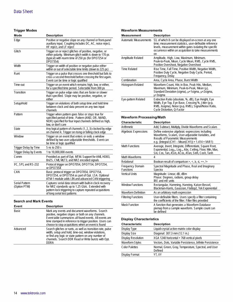
Trigger ModesMode DescriptionEdge Positive or negative slope on any channel or front-panel
auxiliary input. Coupling includes DC, AC, noise reject,HF reject, and LF reject
Glitch Trigger on or reject glitches of positive, negative, oreither polarity. Minimum glitch width is down to 170 ps(typical) with rearm time of 250 ps (for DPO7254 orDPO7354)
Width Trigger on width of positive or negative pulse eitherwithin or out of selectable time limits (down to 225 ps)
Runt Trigger on a pulse that crosses one threshold but fails tocross a second threshold before crossing the first again.Event can be time or logic qualified
Time-out Trigger on an event which remains high, low, or either,for a specified time period. Selectable from 300 ps
Transition Trigger on pulse edge rates that are faster or slowerthan specified. Slope may be positive, negative, oreither
Setup/Hold Trigger on violations of both setup time and hold timebetween clock and data present on any two inputchannels
Pattern Trigger when pattern goes false or stays true forspecified period of time. Pattern (AND, OR, NAND,NOR) specified for four input channels defined as high,low, or don't care
State Any logical pattern of channels (1, 2, 3) clocked by edgeon channel 4. Trigger on rising or falling clock edge
Window Trigger on an event that enters or exits a windowdefined by two user-adjustable thresholds. Event canbe time or logic qualified
Trigger Delay by Time 5 ns to 250 sTrigger Delay by Events 1 to 10,000,000 eventsComm Provided as part of Opt. MTM. Support for AMI, HDB3,
BnZS, CMI, MLT3, and NRZ encoded signalsI2C, SPI, and RS-232 Protocol trigger on DPO7054, DPO7154, DPO7254,
or DPO7354CAN Basic protocol trigger on DPO7054, DPO7154,
DPO7254, or DPO7354 as part of Opt. LSA. OptionalATM-1 module adds LIN and advanced CAN triggering
Serial Pattern(Option PTM)
Captures serial data stream with built-in clock recoveryfor NRZ standards up to 1.25 Gb/s. Extended withpattern lock triggering to capture repeated acquisitionsof long serial test patterns
Search and Mark EventsEvent DescriptionBasic Mark any events and document waveforms. Search
positive, negative slopes or both on any channels.Event table summarizes all found events. All events aretime stamped in reference to trigger position. Users canchoose to stop acquisitions when an event is found
Advanced Search glitches or runts, as well as transition rate, pulsewidth, setup and hold, time-out, window violations,or find any logic or state pattern on any number ofchannels. Search DDR Read or Write bursts with Opt.DDRA
Waveform MeasurementsMeasurement DescriptionAutomatic Measurements 53, of which 8 can be displayed on-screen at any one
time; measurement statistics, user-definable referencelevels, measurement within gates isolating the specificoccurrence within an acquisition to take measurementson
Amplitude Related Amplitude, High, Low, Maximum, Minimum,Peak-to-Peak, Mean, Cycle Mean, RMS, Cycle RMS,Positive Overshoot, Negative Overshoot
Time Related Rise Time, Fall Time, Positive Width, Negative Width,Positive Duty Cycle, Negative Duty Cycle, Period,Frequency, Delay
Combination Area, Cycle Area, Phase, Burst WidthHistogram Related Waveform Count, Hits in Box, Peak Hits, Median,
Maximum, Minimum, Peak-to-Peak, Mean (μ),Standard Deviation (sigma), μ+1sigma, μ+2sigma,μ+3sigma
Eye-pattern Related Extinction Ratio (absolute, %, dB), Eye Height, EyeWidth, Eye Top, Eye Base, Crossing %, Jitter (p-p,RMS, 6sigma), Noise (p-p, RMS), Signal/Noise Ratio,Cycle Distortion, Q-Factor
Waveform Processing/MathCharacteristic DescriptionArithmetic Add, Subtract, Multiply, Divide Waveforms and ScalarsAlgebraic Expressions Define extensive algebraic expressions including
Waveforms, Scalars, User-adjustable Variables, andResults of Parametric Measurementse.g. (Integral (CH1 – Mean(CH1)) × 1.414 × VAR1)
Math Functions Average, Invert, Integrate, Differentiate, Square Root,Exponential, Log10, Log e, Abs, Ceiling, Floor, Min, Max,Sin, Cos, Tan, ASin, ACos, ATan, Sinh, Cosh, Tanh
Math Waveforms 4Relational Boolean result of comparison >, <, ≥, ≤, ==, !=Frequency DomainFunctions
Spectral Magnitude and Phase, Real and ImaginarySpectra
Vertical Units Magnitude: Linear, dB, dBmPhase: Degrees, radians, group delayIRE and mV units
Window Functions Rectangular, Hamming, Hanning, Kaiser-Bessel,Blackman-Harris, Gaussian, Flattop2, Tek Exponential
Waveform Definition As an arbitrary math expressionFiltering Functions User-definable filters. Users specify a filter containing
the coefficients of the filter. Filter files providedMask Function A function that generates a Waveform Database
pixmap from a sample waveform. Sample count canbe defined
Display CharacteristicsCharacteristic DescriptionDisplay Type Liquid-crystal active-matrix color displayDisplay Size Diagonal: 307.3 mm (12.1 in.)Display Resolution XGA 1240 horizontal × 768 vertical pixelsWaveform Styles Vectors, Dots, Variable Persistence, Infinite PersistenceColor Palettes Normal, Green, Gray, Temperature, Spectral, and User
DefinedDisplay Format YT, XY
14 www.tektronix.com

Digital Phosphor Oscilloscopes — DPO7000 Series
Computer System and PeripheralsCharacteristic DescriptionOperating System Windows XPCPU Intel Pentium 4, 3.4 GHz processorPC System Memory 2 GBHard Disk Drive Rear-panel, removable hard disk drive, 80 GB capacityCD/DVD Drive Front-panel CD-R/W, DVD-R driveMouse Optical wheel mouse, USB interface
Input/Output PortsPort DescriptionFront PanelProbe CompensatorOutput
Front-panel pins. Amplitude 1 V ±20% into a ≥50 Ωload; 500 mV from base to top into a 50 Ω load,frequency 1 kHz ±5%
Recovered Clock(for DPO7254 orDPO7354 only)
BNC connector, ≤1.25 Gb/s, Output swing ≥130 mVp-pinto 50 Ω. Requires Option MTM to enable
Recovered Data (forDPO7254 or DPO7354only)
BNC connector, ≤1.25 Gb/s, Output swing 200 mV into50 Ω. Requires Option MTM to enable
USB 2.0 Port One USB 2.0 host connectorAux Trigger Input See trigger specificationSide PanelParallel Port IEEE 1284, DB-25 connectorAudio Ports Miniature phone jacksKeyboard Port PS-2 compatibleMouse Port PS-2 compatibleUSB Ports Four USB 2.0 host connectorsLAN Port RJ-45 connector, supports 10BASE-T, 100BASE-T, and
Gigabit EthernetSerial Port DB-9 COM1 portVGA Video Port DB-15 female connector; connect a second monitor
to use dual-monitor display mode. Supports basicrequirements of PC99 specifications
Oscilloscope VGA VideoPort
DB-15 female connector, 31.6 kHz sync, EIA RS-343Acompliant, connect to show the oscilloscope display,including live waveforms on an external monitor orprojector
Rear PanelPower 100 to 240 VRMS ±10%, 47 to 63 Hz, <550 W
115 VRMS ±10%, 360 to 440 HzCAT I, <500 VA
Analog Signal Output BNC connector provides a buffered version of the signalthat is attached to the CH3 input
Amplitude 50 mV/div ±20% into a 1 MΩ load, 25 mV/div ±20%into a 50 Ω load
Bandwidth 100 MHz into a 50 Ω loadExternal Time BaseReference In
BNC connector, time base system can phase lock toexternal 10 MHz reference
Aux Out (Software switchable)Time base referenceout
BNC connector, provides TTL-compatible output ofinternal 10 MHz reference oscillator
Trigger output BNC connector provides a TTL-compatible, polarityswitchable pulse when the oscilloscope triggers
GPIB Port IEEE 488.2 standard
Physical CharacteristicsBenchtop ConfigurationDimension mm in.Height 292 11.48Width 451 17.75Depth 265 10.44Weight kg lb.Net 15 32Shipping 28.9 63.75Rackmount ConfigurationDimension mm in.Height 331 12.25Width 479 18.85Depth (from rackmountingear to back of instrument)
231.75 9.12
Weight kg lb.Net 17.4 37.5Rackmount Kit 2.5 5.5
Mechanical
Cooling – Required ClearanceDimension mm in.Top 0 0Bottom 0 0Left Side 76 3Right Side 0 0Front 0 0Rear 0 0
www.tektronix.com 15
Data Sheet
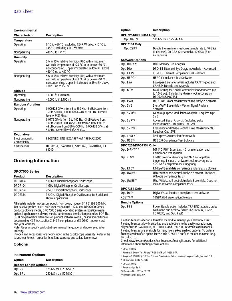
EnvironmentalCharacteristic DescriptionTemperatureOperating 0 °C to +50 °C, excluding CD-R/W drive; +10 °C to
+45 °C, including CD-R/W driveNonoperating –40 °C to +71 °CHumidityOperating 5% to 95% relative humidity (RH) with a maximum
wet bulb temperature of +29 °C at or below +50 °C,noncondensing. Upper limit derated to 45% RH above+30 °C up to +50 °C
Nonoperating 5% to 95% relative humidity (RH) with a maximumwet bulb temperature of +29 °C at or below +60 °C,noncondensing. Upper limit derated to 45% RH above+30 °C up to +50 °C
AltitudeOperating 10,000 ft. (3,048 m)Nonoperating 40,000 ft. (12,190 m)Random VibrationOperating 0.000125 G2/Hz from 5 to 350 Hz, –3 dB/octave from
350 to 500 Hz, 0.0000876 G2/Hz at 500 Hz. Overalllevel of 0.27 GRMS
Nonoperating 0.0175 G2/Hz from 5 to 100 Hz, –3 dB/octave from100 to 200 Hz, 0.00875 G2/Hz from 200 to 350 Hz,–3 dB/octave from 350 to 500 Hz, 0.006132 G2/Hz at500 Hz. Overall level of 2.28 GRMS
RegulatoryElectromagneticCompatibility
93/68/EEC; EN61326:1997 +A1 1998+A2:2000
Certifications UL 3111-1, CSA1010.1, ISO11469, EN61010-1, IEC61010-1
Ordering Information
DPO7000 SeriesProduct DescriptionDPO7054 500 MHz Digital Phosphor OscilloscopeDPO7104 1 GHz Digital Phosphor OscilloscopeDPO7254 2.5 GHz Digital Phosphor OscilloscopeDPO7354 3.5 GHz Digital Phosphor Oscilloscope for Serial and
Digital applicationsAll Models Include: Accessory pouch, front cover, mouse, (4) P6139B 500 MHz,10x passive probes, quick-start user manual (071-173x-xx), DPO7000 Seriesproduct software media, DPO7000 Series operating system restoration media,optional applications software media, performance verification procedure PDF file,GPIB programmer's reference (on product software media), calibration certificatedocumenting NIST traceability, Z 540-1 compliance and ISO9001, power cord,one-year warranty.Note: User to specify quick-start user manual language, and power plug whenordering.(Probes and accessories are not included in the oscilloscope warranty. Refer to thedata sheet for each probe for its unique warranty and calibration terms.)
Options
Instrument OptionsOption DescriptionRecord Length OptionsOpt. 2RL 125 MS max, 25 MS/ChOpt. 5RL 250 MS max, 50 MS/Ch
Option DescriptionDPO7254/DPO7354 Only
Opt. 10RL*5 500 MS max, 125 MS/ChDPO7104 Only
Opt. 2SR*2 Double the maximum real-time sample rate to 40 GS/s(1 channel), 20 GS/s (2 channels), 10 GS/s (3 or4 channels)
Software OptionsOpt. DDRA*9 DDR Memory Bus AnalysisOpt. DJA DPOJET Jitter and Eye Diagram Analysis – AdvancedOpt. ET3*3 TDSET3 Ethernet Compliance Test SoftwareOpt. HEAC*11 HEAC Compliance Test SoftwareOpt. LSA Low-speed Serial Analysis includes CAN Trigger, and
CAN/LIN Decode and AnalysisOpt. MTM Mask Testing for Serial Communication Standards (up
to 1.5 Gb/s). Includes hardware clock recovery onDPO7254/DPO7354
Opt. PWR DPOPWR Power Measurement and Analysis SoftwareOpt. SVE SignalVu™ Essentials – Vector Signal Analysis
SoftwareOpt. SVM*10 General-purpose Modulation Analysis. Requires Opt.
SVEOpt. SVP*10 Advanced Signal Analysis (including pulse
measurements). Requires Opt. SVEOpt. SVT*10 Frequency and Phase Settling Time Measurements.
Requires Opt. SVEOpt. TEKEXP TekExpress Automation FrameworkOpt. USB*4 USB 2.0 Compliance Test SoftwareDPO7254/DPO7354 OnlyOpt. D-PHY*5, 9 MIPI® D-PHY Essentials – Characterization and
Compliance test solutionOpt. PTM*5 8b/10b protocol decoding and NRZ serial pattern
triggering. Includes hardware clock recovery up to1.25 Gb/s and pattern lock triggering
Opt. RTE*5 RT-Eye® Serial data compliance and analysis softwareOpt. UWB*5 Ultra-Wideband Spectral Analysis Software. Includes
WiMedia compliance testsOpt. UWBE*5 Ultra-Wideband Spectral Analysis Essentials. Does not
include WiMedia compliance testsDPO7354 OnlyOpt. DVI*8 Digital Visual Interface compliance test softwareXGBT*8, 11 10GBASE-T Automation SolutionBundle OptionsOpt. PS1 Power Bundle option includes TPA-BNC adapter, probe
calibration and deskew fixture 067-1686-xx, P5205,TCP0030, and Opt. PWR
Floating licenses offer an alternative method to manage your Tektronix asset.Floating licenses allow license-key enabled options to be easily moved amongall your DPO/DSA70000B, MSO70000, and DPO7000 Tektronix oscilloscopes.Floating licenses are available for many license-key enabled options. To order afloating version of an option license add “DPOFL-“ prefix to the option name. (e.g.DPOFL-ET3)Check www.tek.com/products/oscilloscopes/floatinglicenses for additionalinformation about floating license options.*2 DPO7104 only.*3 Requires Ethernet Test Fixture TF-GBE-ATP or TF-GBE-BTP.*4 Requires TDSUSBF (USB Test Fixture). Greater than 2 GHz bandwidth required for high-speed USB.*5 DPO7254 or DPO7354 only.*8 DPO7354 only.*9 Requires Opt. DJA.*10 Requires Opt. SVE or SVEM.*11 Requires Opt. TEKEXP.
16 www.tektronix.com

Digital Phosphor Oscilloscopes — DPO7000 Series
User Manual OptionsOption DescriptionOpt. L0 English manualOpt. L1 French manualOpt. L3 German manualOpt. L5 Japanese manualOpt. L7 Simple Chinese manualOpt. L8 Standard Chinese manualOpt. L9 Korean manualOpt. L10 Russian manual
Power Plug OptionsOption DescriptionOpt. A0 North AmericaOpt. A1 Universal European UnionOpt. A2 UKOpt. A3 AustraliaOpt. A5 SwitzerlandOpt. A6 JapanOpt. A10 ChinaOpt. A11 IndiaOpt. A99 No power cord
Service Options(Probes and accessories are not included in the oscilloscope warranty. Refer to thedata sheet for each probe for its unique warranty and calibration terms.)Option DescriptionOpt. C3 Calibration Service 3 YearsOpt. C5 Calibration Service 5 YearsOpt. D1 Calibration Data ReportOpt. D3 Calibration Data Report 3 Years (with Opt. C3)Opt. D5 Calibration Data Report 5 Years (with Opt. C5)Opt. G3 Complete Care 3 Years (includes loaner, scheduled
calibration and more)Opt. G5 Complete Care 5 Years (includes loaner, scheduled
calibration and more)Opt. R3 Repair Service 3 YearsOpt. R5 Repair Service 5 Years
Recommended Accessories
ProbesProbe DescriptionTCP0150 20 MHz TekVPI™ AC/DC 150 A current probeTCP202*6 DC coupled current probeTDP0500 500 MHz TekVPI high-voltage differential probeTDP1000 1 GHz TekVPI high-voltage differential probeTDP1500 1.5 GHz TekVPI high-voltage differential probeTDP3500 3.5 GHz TekVPI high-voltage differential probeTAP3500 3.5 GHz TekVPI active single-ended probeTAP2500 2.5 GHz TekVPI active single-ended probeTAP1500 1.5 GHz TekVPI active single-ended probeTCP0030 >120 MHz TekVPI AC/DC 30 A current probeTPA-BNC TekProbe-BNC Level 2 to TekVPI adapterP6139B 500 MHz, passive probe (four included with each
model)P6158 3 GHz, 20x low C probeP6247*6 1 GHz differential probeP6243*6 1 GHz active probeP6245*6 1.5 GHz active probeP6248*6 1.5 GHz differential probeP6251*6 1 GHz high-voltage differential probeP6330*6 3 GHz differential probeP6246*6 400 MHz differential probeP6101B 1x passive probe 15 MHzTCPA300/TCPA400*6 Series current measurement systemsP5200/P5205/P5210*6 High-voltage differential probesP5100/P6015A High-voltage probes*6 Probe requires TPA-BNC adapter.
CablesCable DescriptionGPIB Cable (1 m) Order 012-0991-01GPIB Cable (2 m) Order 012-0991-00Centronics Cable Order 012-1214-xx
AccessoriesAccessory DescriptionMini Keyboard (USBinterface)
Order 119-7083-xx (fits in accessory pouch)
Keyboard (USB interface) Full-size keyboard with 4 port USB hub. Order119-6633-00
Transit Case Order 016-1970-xxRackmount Kit Order 016-1985-xxFront Hard-drive Optionfor Rackmount Kit
Order 016-1979-xx
Removable HD Spare Order 065-0744-xxOscilloscope Cart Order K420 (requires 407-5192-xx bracket set)WSTRO WaveStar™ Windows application for remote access
www.tektronix.com 17

Data Sheet
Test FixturesFixture DescriptionTDSUSBF Test fixture for use with Opt. USBProbe Calibration/PowerDeskew Fixture
Order 067-1686-xx
TF-GBE-ATP 1000/100/10BASE-T Advanced Ethernet Test Package,includes test fixture, RJ-45 interconnect cable, and1000BASE-T jitter test channel cable
TF-GBE-BTP 1000/100/10BASE-T Basic Ethernet Test Package,includes test fixture and RJ-45 interconnect cable
ATM-1 Advanced CAN and LIN triggering module
AdaptersAdapter DescriptionP6701B*6 Optical/Electrical converter (Multi Mode)P6703B*6 Optical/Electrical converter (Single Mode)*6 Probe requires TPA-BNC adapter.
Optional SoftwareSoftware DescriptionPDU-R Prodigy RS-232/UART decode applicationPDI-R Prodigy I2C decode applicationPDS-R Prodigy SPI decode applicationPDF-R Prodigy FlexRay decode applicationSIGEXPTE NI LabVIEW SignalExpress™ Tektronix Edition
Software (Full Version)
Instrument UpgradesTo upgrade your DPO7000 Series oscilloscope, order DPO7UP with option asnoted:
Option DescriptionTo upgrade record length:RL02 From Standard Configuration to Opt. 2RL ConfigurationRL05 From Standard Configuration to Opt. 5RL ConfigurationRL010*5 On DPO7254 or DPO7354 from Standard Configuration
to Opt. 10RL ConfigurationRL25 From Opt. 2RL Configuration to Opt. 5RL ConfigurationRL210*5 On DPO7254 or DPO7354 from Opt. 2RL Configuration
to Opt. 10RL ConfigurationRL510*5 On DPO7254 or DPO7354 from Opt. 5RL Configuration
to Opt. 10RL ConfigurationTo upgrade DPO7000 Series with:ASM*12 Advanced Search and MarkCP2*7 TDSCPM2 ANSI/ITU Telecom pulse compliance testing
softwareD-PHY*5, 9 MIPI® D-PHY EssentialsDDRA*9 Opt. DDRADJAM Opt. DJADJEM*12 DPOJET Jitter and Eye Diagram Analysis – EssentialsDVI*8 Opt. DVIET3*3 Opt. ET3J2 TDSDDM2 disk drive analysis softwareLSA Opt. LSALT*12 Waveform Limit TestMTM Opt. MTMPTM*5 To upgrade DPO7254 or DPO7354 with Opt. PTMPWR Opt. PWRRTE*5 Opt. RTE or TDSRT eye softwareSVEM Opt. SVESVM*10 Opt. SVMSVP*10 Opt. SVPSVT*10 Opt. SVTUSB*4 Opt. USBUWB*5 Opt. UWBUWBE*5 Opt. UWBE*3 Requires Ethernet Test Fixture TF-GBE-ATP or TF-GBE-BTP.*4 Requires TDSUSBF (USB Test Fixture). Greater than 2 GHz bandwidth required for high-speed USB.*5 DPO7254 or DPO7354 only.*7 Requires Opt. MTM.*8 DPO7354 only.*9 Requires Opt. DJA.*10 Requires Opt. SVE or SVEM.*12 Included as standard feature on units with serial number above B070000 and C010100.
Product(s) are manufactured in ISO registered facilities.
18 www.tektronix.com

Digital Phosphor Oscilloscopes — DPO7000 Series
www.tektronix.com 19

Data Sheet Contact Tektronix:ASEAN / Australasia (65) 6356 3900
Austria 00800 2255 4835*
Balkans, Israel, South Africa and other ISE Countries +41 52 675 3777
Belgium 00800 2255 4835*
Brazil +55 (11) 3759 7600
Canada 1 800 833 9200
Central East Europe, Ukraine, and the Baltics +41 52 675 3777
Central Europe & Greece +41 52 675 3777
Denmark +45 80 88 1401
Finland +41 52 675 3777
France 00800 2255 4835*
Germany 00800 2255 4835*
Hong Kong 400 820 5835
India 000 800 650 1835
Italy 00800 2255 4835*
Japan 81 (3) 6714 3010
Luxembourg +41 52 675 3777
Mexico, Central/South America & Caribbean (52) 56 04 50 90
Middle East, Asia, and North Africa +41 52 675 3777
The Netherlands 00800 2255 4835*
Norway 800 16098
People’s Republic of China 400 820 5835
Poland +41 52 675 3777
Portugal 80 08 12370
Republic of Korea 001 800 8255 2835
Russia & CIS +7 (495) 7484900
South Africa +41 52 675 3777
Spain 00800 2255 4835*
Sweden 00800 2255 4835*
Switzerland 00800 2255 4835*
Taiwan 886 (2) 2722 9622
United Kingdom & Ireland 00800 2255 4835*
USA 1 800 833 9200
* European toll-free number. If not accessible, call: +41 52 675 3777
Updated 25 May 2010
For Further Information. Tektronix maintains a comprehensive, constantly expandingcollection of application notes, technical briefs and other resources to help engineers workingon the cutting edge of technology. Please visit www.tektronix.com
Copyright © Tektronix, Inc. All rights reserved. Tektronix products are covered by U.S. and foreign patents,issued and pending. Information in this publication supersedes that in all previously published material.Specification and price change privileges reserved. TEKTRONIX and TEK are registered trademarks ofTektronix, Inc. All other trade names referenced are the service marks, trademarks, or registered trademarksof their respective companies.
28 Oct 2010 4MW-19046-19
www.tektronix.com