Digital Monochrome and Color Megapixel Progressive … · Digital Monochrome and Color Megapixel...
36
Digital Monochrome and Color Megapixel Progressive Scan Cameras CV-M4 + /M4 + CL CV-M7 + /M7 + CL Operation Manual Camera: Revision C Manual: Version 1.4 M4plusBmanJune01.doc JPT 01-06-21
Transcript of Digital Monochrome and Color Megapixel Progressive … · Digital Monochrome and Color Megapixel...
Digital Monochrome and Color
Megapixel Progressive Scan Cameras
CV-M4+/M4+CL CV-M7+/M7+CL
Operation Manual
Camera: Revision C Manual: Version 1.4
M4plusBmanJune01.doc JPT 01-06-21
CV-M4+/M4+CL, CV-M7+/M7+CL
- 1 -
Table of contents 1. General......................................................................................................... 2 2. Standard Composition ....................................................................................... 2 3. Main Features ................................................................................................. 2 4. Locations and Functions..................................................................................... 3 5. Pin Assignment................................................................................................ 4
5.1. 12-pin Multi-connector (DC-IN/RS232C)............................................................ 4 5.2. Digital Output Connector for EIA-644 (LVDS)...................................................... 4 5.3. Digital Output Connector for Camera Link ........................................................ 5 5.4. Input and Output Circuits ............................................................................ 6
5.4.1. Video output ..................................................................................... 6 5.4.2. Trigger input Multi Shutter input ............................................................. 6 5.4.3. Composite Sync output......................................................................... 6 5.4.4. LVDS interface................................................................................... 6 5.4.5. Camera Link interface.......................................................................... 7
5.5. CV-M4+ Block Diagram................................................................................. 8 6. Functions and Operations ................................................................................... 8
6.1. Basic functions ......................................................................................... 8 6.2. Output of Timing Signals ........................................................................... 11 6.3. Continuous Operation (Non triggered) ........................................................... 12 6.4. External Trigger Modes ............................................................................. 15 6.5. Edge Pre-select Mode ............................................................................... 16 6.6. Pulse Width Control Mode .......................................................................... 18 6.7. Frame-delay read out Mode........................................................................ 19 6.8. Frame-delay read out Mode with multiple exposure........................................... 20 6.9. Other Functions. ..................................................................................... 21
7. Configuring the Camera ................................................................................... 22 7.1. Mode setting SW1 on rear .......................................................................... 22 7.2. Mode setting SW301 inside ......................................................................... 22 7.3. Internal Switch and Jumper Settings ............................................................. 22 7.4. RS-232C control ...................................................................................... 23 7.5. CV-M4+ command list................................................................................ 24 7.6. Camera Control Tool for CV-M4+ .................................................................. 25
7.6.1. Control Tool Windows ........................................................................ 25 7.6.2. Camera Control Tool Software.............................................................. 26 7.6.3. Using the Camera Control Tool ............................................................. 28
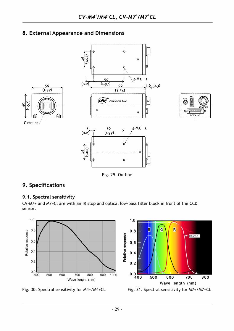
8. External Appearance and Dimensions ................................................................... 29 9. Specifications ............................................................................................... 29
9.1. Spectral sensitivity .................................................................................. 29 9.2. Specification table .................................................................................. 30
10. Appendix ................................................................................................... 31 10.1. Precautions.......................................................................................... 31 10.2. Typical CCD Characteristics ...................................................................... 31 10.3. References .......................................................................................... 32 10.4. Camera Link Test points .......................................................................... 32
11. Users Record............................................................................................... 33
CV-M4+/M4+CL, CV-M7+/M7+CL
1. General This manual will cover the following 4 cameras: CV-M4+/CV-M4+CL and CV-M7+/CV-M7+CL. The revision B cameras are updated with a new function, Restart Continuous Trigger mode (RCT). The trigger can be H a-synchronous or H synchronous. Binning is now only vertical. The revision C cameras are updated with improved circuits and new boards. The cameras are based on progressive scan 2/3” CCD megapixel interline transfer sensors. CV-M4+ is a digital monochrome progressive scan CCD camera with LVDS output. CV-M4+CL is a digital monochrome progressive scan CCD camera with Camera Link output. CV-M7+ is a digital RGB color progressive scan CCD camera with LVDS output. CV-M7+CL is a digital RGB color progressive scan CCD camera with Camera Link output. The color cameras use a RGB primary color filter CCD sensor (Bayer color filter). The video output is a single data stream with the RGB signals in sequence. The RGB color decoding should be done in the host PC. The cameras are designed for automated imaging applications, featuring high resolution and high speed within a uniform and compact housing. The high-speed shutter function, asynchronous random trigger mode and partial scan mode allows the camera to capture high quality images of fast moving objects with a high frame rate. It is suitable for industrial applications such as on-line inspection and measurement. Thanks to the EIA-644 (LVDS) digital interface, crisp and clear images are achieved. The CV-M4+CL features the Camera Link standardized multiplexed signal output interface. The latest version of this manual can be downloaded from: www.jai.com The latest version of Camera Control Tool for CV-M4+/M4+CL and CV-M7+/CV-M+7CL can be downloaded from: www.jai.com For camera revision history, please contact your local JAI distributor.
2. Standard Composition The standard camera composition consists of the camera main body.
3. Main Features
• Digital 2/3” megapixel progressive scan CCD cameras • 1392 (h) x 1040 (v) 6.45µm square pixels (1380 x 1030 pixels read out) • Monochrome versions and color versions for host PC RGB color coding • 8 bit digital output as LVDS (EIA 644)(digitization via 10 bit A/D) • Camera Link versions CV-M4+CL/CV-M7+CL features full 10-bit output • Analog video output for iris control • 24 frames/second with full resolution • Increased frame rate with 1/2, 1/4 and 1/8 partial scan • Vertical binning for higher frame rates and higher sensitivity on monochrome versions • Shutter speed 1/24 to 1/10,000 second in 10 steps • H synchronous and H a-synchronous triggered shutter • Edge pre-select and pulse width controlled external trigger modes • Restart Continuous Trigger mode • Frame-delay and smearless readout modes • Multiple exposure with up to 6 exposures within a single frame • Trigger and timing signals via LVDS or Camera Link • Camera setup via switches or RS-232C/Camera Link • Windows 98/NT/Win2000/XP control software
- 2 -
CV-M4+/M4+CL, CV-M7+/M7+CL
- 3 -
4. Locations and Functions
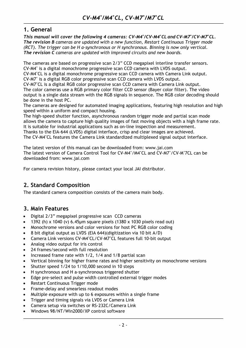
1. CCD sensor 2. Lens mount (C-mount) *) 3. Rear panel with SW1 4. Digital output connector 5. DC in/Trigger in/RS-232C connector 6. Gain potentiometer 7. Mounting holes M3
*) Note: Rear protrusion on C-mount lens must be less than 9.0mm. When IR cut filter is used, it must be less than 6.0 mm.
The IR cut filter is placed in the C-mount thread. The C-mount 25 mm IR cut filter must be ordered separately.
Fig. 1. Locations
CV-M4+/M4+CL, CV-M7+/M7+CL
- 4 -
5. Pin Assignment
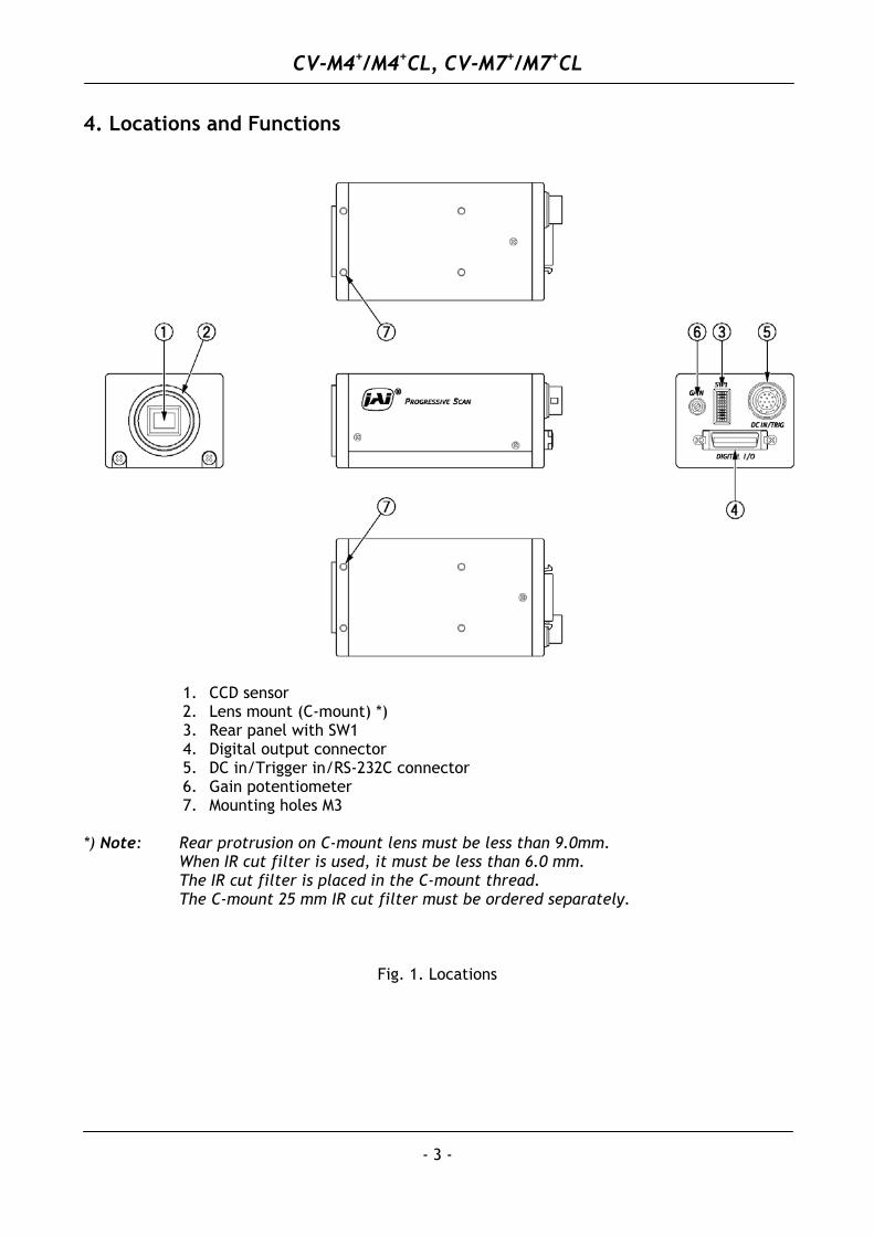
5.1. 12-pin Multi-connector (DC-IN/RS232C) Type: HR10A-10R-12PB-01 (Hirose) male. (Seen from rear of camera.)
3
45
6
7
8
9
10
11 12
1
2
*) Iris video out without sync. Refer to 5.4.1 video output
*1) EEN or c. sync out select by RS232C command SE Fig. 2. 12-pin connector. *2) input on 12-pin con. or LVDS/(CL) by command TP or int. SW301-1
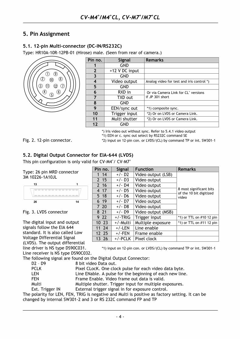
5.2. Digital Output Connector for EIA-644 (LVDS) This pin configuration is only valid for CV-M4+/ CV-M7+ Type: 26 pin MRD connector 3M 10226-1A10JL
Fig. 3. LVDS connector The digital input and output signals follow the EIA 644 standard. It is also called Low Voltage Differential Signal (LVDS). The output differential line driver is NS type DS90C031. *1) input on 12-pin con. or LVDS/(CL) by command TP or int. SW301-1
Pin no. Signal Remarks 1 GND
2 +12 V DC input
3 GND
4 Video output Analog video for test and iris control *)
5 GND
6 RXD in 7 TXD out
Or via Camera Link for CL+ versions if JP 301 short
8 GND
9 EEN/sync out *1) composite sync.
10 Trigger input *2) Or on LVDS or Camera Link.
11 Multi shutter *2) Or on LVDS or Camera Link.
12 GND
Pin no. Signal Function Remarks 1 14 +/- D2 Video output (LSB) 2 15 +/- D3 Video output 2 16 +/- D4 Video output 4 17 +/- D5 Video output 5 18 +/- D6 Video output 6 19 +/- D7 Video output 7 20 +/- D8 Video output 8 21 +/- D9 Video output (MSB)
8 most significant bits of the 10 bit digitized video
9 22 +/-TRIG Trigger input *1) or TTL on #10 12 pin
10 23 +/-Multi Multiple exposure *1) or TTL on #11 12 pin
11 24 +/-LEN Line enable
12 25 +/-FEN Frame enable
13 26 +/-PCLK Pixel clock
13
14
1
26
Line receiver is NS type DS90C032. The following signal are found on the Digital Output Connector: D2 – D9 8 bit video Data out. PCLK Pixel CLocK. One clock pulse for each video data byte. LEN Line ENable. A pulse for the beginning of each new line. FEN Frame Enable. Video frame out data is valid. Multi Multiple shutter. Trigger input for multiple exposures. Ext. Trigger IN External trigger signal in for exposure control. The polarity for LEN, FEN, TRIG is negative and Multi is positive as factory setting. It can be changed by internal SW301-2 and 3 or RS 232C command FP and TP
CV-M4+/M4+CL, CV-M7+/M7+CL
- 5 -
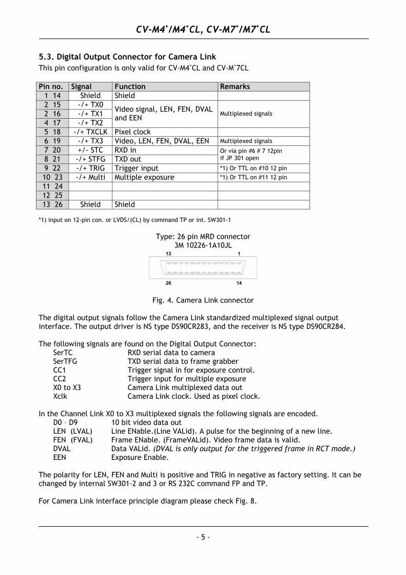
5.3. Digital Output Connector for Camera Link This pin configuration is only valid for CV-M4+CL and CV-M+7CL
Pin no. Signal Function Remarks
1 14 Shield Shield
2 15 -/+ TX0 2 16 -/+ TX1 4 17 -/+ TX2
Video signal, LEN, FEN, DVAL and EEN
Multiplexed signals
5 18 -/+ TXCLK Pixel clock
6 19 -/+ TX3 Video, LEN, FEN, DVAL, EEN Multiplexed signals
7 20 +/- STC RXD in 8 21 -/+ STFG TXD out
Or via pin #6 # 7 12pin if JP 301 open
9 22 -/+ TRIG Trigger input *1) Or TTL on #10 12 pin
10 23 -/+ Multi Multiple exposure *1) Or TTL on #11 12 pin
11 24
12 25
13 26 Shield Shield *1) input on 12-pin con. or LVDS/(CL) by command TP or int. SW301-1
Type: 26 pin MRD connector
3M 10226-1A10JL 13
14
1
26
Fig. 4. Camera Link connector The digital output signals follow the Camera Link standardized multiplexed signal output interface. The output driver is NS type DS90CR283, and the receiver is NS type DS90CR284. The following signals are found on the Digital Output Connector: SerTC RXD serial data to camera SerTFG TXD serial data to frame grabber CC1 Trigger signal in for exposure control. CC2 Trigger input for multiple exposure X0 to X3 Camera Link multiplexed data out Xclk Camera Link clock. Used as pixel clock. In the Channel Link X0 to X3 multiplexed signals the following signals are encoded. D0 – D9 10 bit video data out LEN (LVAL) Line ENable.(Line VALid). A pulse for the beginning of a new line. FEN (FVAL) Frame ENable. (FrameVALid). Video frame data is valid. DVAL Data VALid. (DVAL is only output for the triggered frame in RCT mode.) EEN Exposure Enable. The polarity for LEN, FEN and Multi is positive and TRIG in negative as factory setting. It can be changed by internal SW301-2 and 3 or RS 232C command FP and TP. For Camera Link interface principle diagram please check Fig. 8.
CV-M4+/M4+CL, CV-M7+/M7+CL
5.4. Input and Output Circuits
GND
#4/1275
VideoOutput
NC68p
1µ2L
500 mVGND
Blacklevel
GND
#4/1275
VideoOutput
NC68p
1µ2L
500 mVGND
Blacklevel
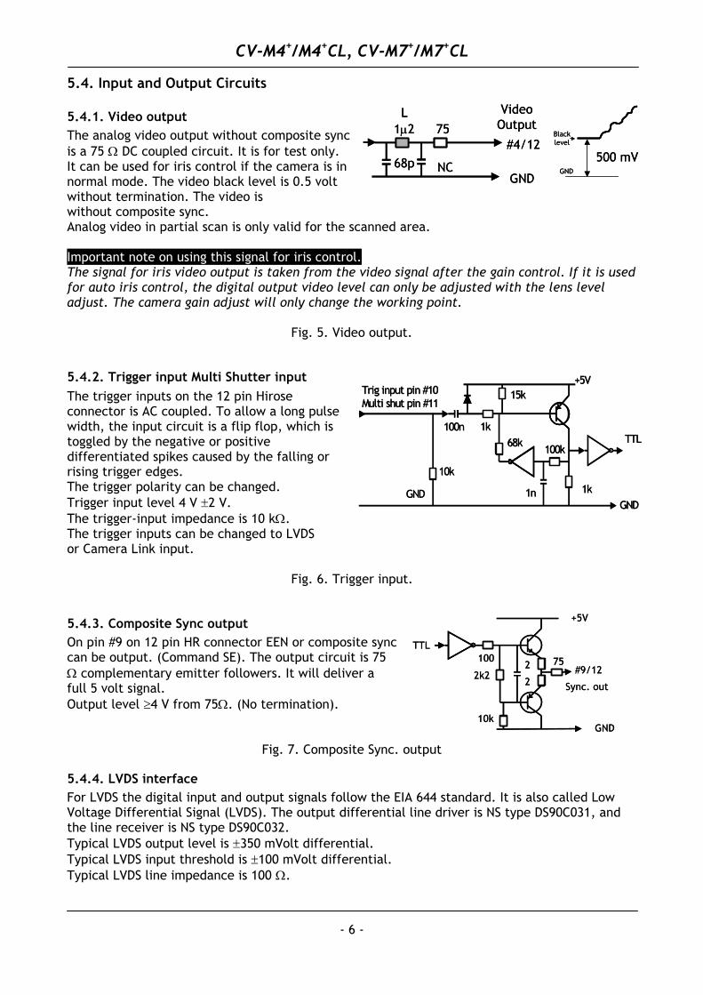
5.4.1. Video output The analog video output without composite sync is a 75 Ω DC coupled circuit. It is for test only. It can be used for iris control if the camera is in normal mode. The video black level is 0.5 volt without termination. The video is without composite sync. Analog video in partial scan is only valid for the scanned area. Important note on using this signal for iris control. The signal for iris video output is taken from the video signal after the gain control. If it is used for auto iris control, the digital output video level can only be adjusted with the lens level adjust. The camera gain adjust will only change the working point.
Fig. 5. Video output.
5.4.2. Trigger input Multi Shutter input
GND
+5V15k
TTL1k
GND
100n
1k
68k100k
1n
10k
Trig input pin #10Multi shut pin #11
GND
+5V15k
TTL1k
GND
100n
1k
68k100k
1n
10k
Trig input pin #10Multi shut pin #11
The trigger inputs on the 12 pin Hirose connector is AC coupled. To allow a long pulse width, the input circuit is a flip flop, which is toggled by the negative or positive differentiated spikes caused by the falling or rising trigger edges. The trigger polarity can be changed. Trigger input level 4 V ±2 V. The trigger-input impedance is 10 kΩ. The trigger inputs can be changed to LVDS or Camera Link input.
Fig. 6. Trigger input.
GND
+5V
2
2
10k
2k275
TTL100
#9/12
Sync. out
GND
+5V
2
2
10k
2k275
TTL100
#9/12
Sync. out
5.4.3. Composite Sync output On pin #9 on 12 pin HR connector EEN or composite sync can be output. (Command SE). The output circuit is 75 Ω complementary emitter followers. It will deliver a full 5 volt signal. Output level ≥4 V from 75Ω. (No termination).
Fig. 7. Composite Sync. output
5.4.4. LVDS interface For LVDS the digital input and output signals follow the EIA 644 standard. It is also called Low Voltage Differential Signal (LVDS). The output differential line driver is NS type DS90C031, and the line receiver is NS type DS90C032. Typical LVDS output level is ±350 mVolt differential. Typical LVDS input threshold is ±100 mVolt differential. Typical LVDS line impedance is 100 Ω.
- 6 -
CV-M4+/M4+CL, CV-M7+/M7+CL
- 7 -
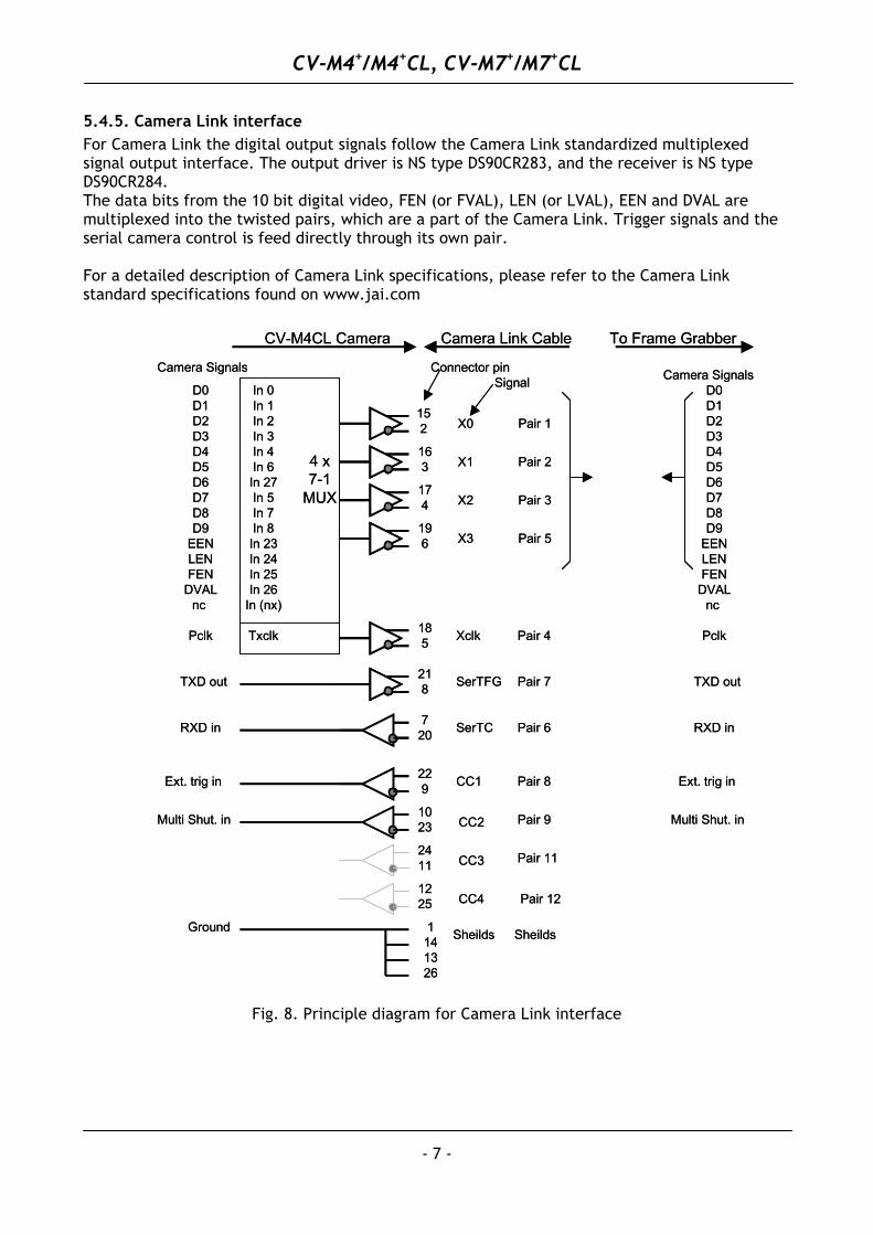
5.4.5. Camera Link interface For Camera Link the digital output signals follow the Camera Link standardized multiplexed signal output interface. The output driver is NS type DS90CR283, and the receiver is NS type DS90CR284. The data bits from the 10 bit digital video, FEN (or FVAL), LEN (or LVAL), EEN and DVAL are multiplexed into the twisted pairs, which are a part of the Camera Link. Trigger signals and the serial camera control is feed directly through its own pair. For a detailed description of Camera Link specifications, please refer to the Camera Link standard specifications found on www.jai.com
1141326
X0
X1
X2
X3
Xclk
SerTFG
SerTC
CC1
CC2
CC3
CC4
Sheilds
4 x7-1
MUX
D0D1D2D3D4D5D6D7D8D9
EENLENFEN
DVALnc
Pclk
In 0In 1In 2In 3In 4In 6In 27In 5In 7In 8In 23In 24In 25In 26
In (nx)
Txclk
152
163
174
196
185
218
720
229
1023
2411
1225
Pair 1
Pair 2
Pair 3
Pair 5
Pair 4
Pair 7
Pair 6
Pair 8
Pair 9
Pair 11
Pair 12
Sheilds
TXD out
RXD in
Ext. trig in
Ground
SignalConnector pin
CV-M4CL Camera
D0D1D2D3D4D5D6D7D8D9
EENLENFEN
DVALnc
Pclk
TXD out
RXD in
Ext. trig in
Camera Link Cable
Camera Signals Camera Signals
To Frame Grabber
Multi Shut. in Multi Shut. in
Fig. 8. Principle diagram for Camera Link interface
CV-M4+/M4+CL, CV-M7+/M7+CL
- 8 -
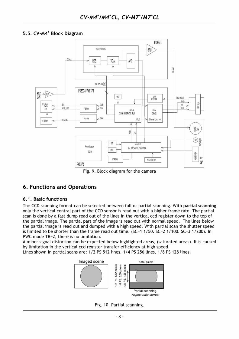
5.5. CV-M4+ Block Diagram
Fig. 9. Block diagram for the camera
6. Functions and Operations
6.1. Basic functions The CCD scanning format can be selected between full or partial scanning. With partial scanning only the vertical central part of the CCD sensor is read out with a higher frame rate. The partial scan is done by a fast dump read out of the lines in the vertical ccd register down to the top of the partial image. The partial part of the image is read out with normal speed. The lines below the partial image is read out and dumped with a high speed. With partial scan the shutter speed is limited to be shorter than the frame read out time. (SC=1 1/50. SC=2 1/100. SC=3 1/200). In PWC mode TR=2, there is no limitation. A minor signal distortion can be expected below highlighted areas, (saturated areas). It is caused by limitation in the vertical ccd register transfer efficiency at high speed. Lines shown in partial scans are: 1/2 PS 512 lines. 1/4 PS 256 lines. 1/8 PS 128 lines.
Imaged scene
Partial scanning.Aspect ratio correct
1380 pixels
1/2
PS
, 512
pix
els
1/8
PS
, 128
pix
els
1/4
PS
, 256
pix
els
Fig. 10. Partial scanning.
CV-M4+/M4+CL, CV-M7+/M7+CL
- 9 -
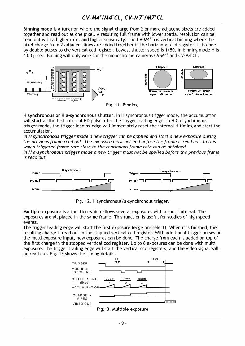
Binning mode is a function where the signal charge from 2 or more adjacent pixels are added together and read out as one pixel. A resulting full frame with lower spatial resolution can be read out with a higher rate, and higher sensitivity. The CV-M4+ has vertical binning where the pixel charge from 2 adjacent lines are added together in the horizontal ccd register. It is done by double pulses to the vertical ccd register. Lowest shutter speed is 1/50. In binning mode H is 43.3 µ sec. Binning will only work for the monochrome cameras CV-M4+ and CV-M4+CL.
1030
pix
els
Normal full scanning.Aspect ratio correct
1380 pixels
515
pixe
ls
Vertical 2:1 binnig
1380 pixels
Aspect ratio not correct
1030
pix
els
Normal full scanning.Aspect ratio correct
1380 pixels
1030
pix
els
Normal full scanning.Aspect ratio correct
1380 pixels
515
pixe
ls
Vertical 2:1 binnig
1380 pixels
Aspect ratio not correct
515
pixe
ls
Vertical 2:1 binnig
1380 pixels
Aspect ratio not correct
Xsg1
Videoout
No V binning
V binning
H
Horizontal ccd register
Ver
tical
ccd
regi
ster Xsg1
Videoout
No V binning
V binning
H
Horizontal ccd register
Ver
tical
ccd
regi
ster
Fig. 11. Binning. H synchronous or H a-synchronous shutter. In H synchronous trigger mode, the accumulation will start at the first internal HD pulse after the trigger leading edge. In HD a-synchronous trigger mode, the trigger leading edge will immediately reset the internal H timing and start the accumulation. In H synchronous trigger mode a new trigger can be applied and start a new exposure during the previous frame read out. The exposure must not end before the frame is read out. In this way a triggered frame rate close to the continuous frame rate can be obtained. In H a-synchronous trigger mode a new trigger must not be applied before the previous frame is read out.
Int. HD
Trigger
Accum
H a-synchronous
Int. HD
Trigger
Accum
Int. HD
Trigger
Accum
H a-synchronous
Int. HD
Trigger
Accum
H synchronous
Int. HD
Trigger
Accum
Int. HD
Trigger
Accum
H synchronous
Fig. 12. H synchronous/a-synchronous trigger.
Multiple exposure is a function which allows several exposures with a short interval. The exposures are all placed in the same frame. This function is useful for studies of high speed events. The trigger leading edge will start the first exposure (edge pre select). When it is finished, the resulting charge is read out in the stopped vertical ccd register. With additional trigger pulses on the multi exposure input, new exposures can be done. The charge from each is added on top of the first charge in the stopped vertical ccd register. Up to 6 exposures can be done with multi exposure. The trigger trailing edge will start the vertical ccd registers, and the video signal will be read out. Fig. 13 shows the timing details.
TRIG G ER
M ULTIPLEEXPO SURE
SHUTTER T IM E(fixed)
ACCUM ULATIO N
CHARG E INV-REG
VIDEO O UT
open openopen
>1H >2H
1 2 3
Fig.13. Multiple exposure
CV-M4+/M4+CL, CV-M7+/M7+CL
- 10 -
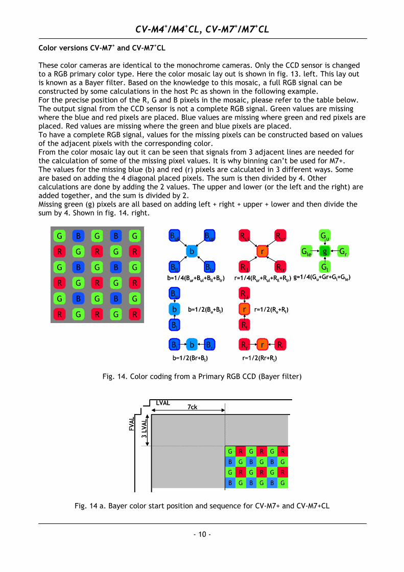
Color versions CV-M7+ and CV-M7+CL These color cameras are identical to the monochrome cameras. Only the CCD sensor is changed to a RGB primary color type. Here the color mosaic lay out is shown in fig. 13. left. This lay out is known as a Bayer filter. Based on the knowledge to this mosaic, a full RGB signal can be constructed by some calculations in the host Pc as shown in the following example. For the precise position of the R, G and B pixels in the mosaic, please refer to the table below. The output signal from the CCD sensor is not a complete RGB signal. Green values are missing where the blue and red pixels are placed. Blue values are missing where green and red pixels are placed. Red values are missing where the green and blue pixels are placed. To have a complete RGB signal, values for the missing pixels can be constructed based on values of the adjacent pixels with the corresponding color.
From the color mosaic lay out it can be seen that signals from 3 adjacent lines are needed for the calculation of some of the missing pixel values. It is why binning can’t be used for M7+.
The values for the missing blue (b) and red (r) pixels are calculated in 3 different ways. Some are based on adding the 4 diagonal placed pixels. The sum is then divided by 4. Other calculations are done by adding the 2 values. The upper and lower (or the left and the right) are added together, and the sum is divided by 2. Missing green (g) pixels are all based on adding left + right + upper + lower and then divide the sum by 4. Shown in fig. 14. right.
Bl
Bu
b b=1/2(Bu+Bl)
Rl
Ru
r r=1/2(Ru+Rl)
Bl b Br
b=1/2(Br+Bl)
Rr r Rl
r=1/2(Rr+Rl)
Bll
Bul
b
Blr
Bur
b=1/4(Bur+Bul+Bll+Blr)
Rll
Rul
r
Rlr
Rur
r=1/4(Rur+Rul+Rll+Rlr)
Gle g
Gu
Gl
Gr
g=1/4(Gu+Gr+Gl+Gle)R
R
R
G
B
G
B
B
G
G
G
G R
R
R
G
G
G
B
G
B
B
G
G R
R
R
G
G
G
Bl
Bu
b b=1/2(Bu+Bl)
Rl
Ru
r r=1/2(Ru+Rl)
Bl b Br
b=1/2(Br+Bl)
Rr r Rl
r=1/2(Rr+Rl)
Bll
Bul
b
Blr
Bur
b=1/4(Bur+Bul+Bll+Blr)
Rll
Rul
r
Rlr
Rur
r=1/4(Rur+Rul+Rll+Rlr)
Gle g
Gu
Gl
Gr
g=1/4(Gu+Gr+Gl+Gle)R
R
R
G
B
G
B
B
G
G
G
G R
R
R
G
G
G
B
G
B
B
G
G R
R
R
G
G
G
R
R
R
G
B
G
B
B
G
G
G
G R
R
R
G
G
G
B
G
B
B
G
G R
R
R
G
G
G
Fig. 14. Color coding from a Primary RGB CCD (Bayer filter)
G
G
R
B
7ckLVAL
FVAL
3 LV
AL
G
G
R
B
G
G
R
B
G
G
R
B
G
G
R
B
G
G
R
B
G
G
R
B
G
G
R
B
7ckLVAL
FVAL
3 LV
AL
G
G
R
B
G
G
R
B
G
G
R
B
G
G
R
B
G
G
R
B
G
G
R
B
G
G
R
B
G
G
R
B
G
G
R
B
G
G
R
B
Fig. 14 a. Bayer color start position and sequence for CV-M7+ and CV-M7+CL
CV-M4+/M4+CL, CV-M7+/M7+CL
- 11 -
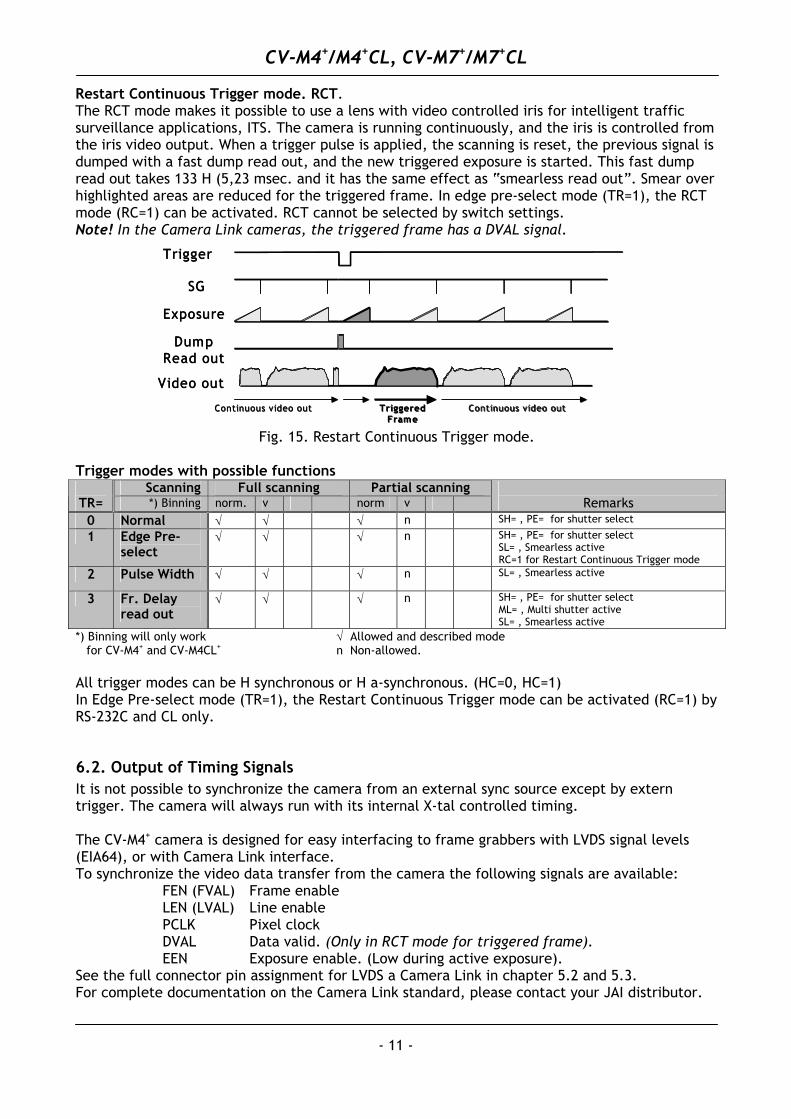
Restart Continuous Trigger mode. RCT. The RCT mode makes it possible to use a lens with video controlled iris for intelligent traffic surveillance applications, ITS. The camera is running continuously, and the iris is controlled from the iris video output. When a trigger pulse is applied, the scanning is reset, the previous signal is dumped with a fast dump read out, and the new triggered exposure is started. This fast dump read out takes 133 H (5,23 msec. and it has the same effect as “smearless read out”. Smear over highlighted areas are reduced for the triggered frame. In edge pre-select mode (TR=1), the RCT mode (RC=1) can be activated. RCT cannot be selected by switch settings. Note! In the Camera Link cameras, the triggered frame has a DVAL signal.
Trigger
SG
Exposure
Video out
DumpRead out
Continuous video out Continuous video outTriggeredFrame
Trigger
SG
Exposure
Video out
DumpRead out
Continuous video out Continuous video outTriggeredFrame
Fig. 15. Restart Continuous Trigger mode. Trigger modes with possible functions
Scanning Full scanning Partial scanning TR= *) Binning norm. v norm v
Remarks
0 Normal √ √ √ n SH= , PE= for shutter select
1 Edge Pre-select
√ √ √ n SH= , PE= for shutter select SL= , Smearless active RC=1 for Restart Continuous Trigger mode
2 Pulse Width √ √ √ n SL= , Smearless active
3 Fr. Delay read out
√ √ √ n SH= , PE= for shutter select ML= , Multi shutter active SL= , Smearless active
*) Binning will only work √ Allowed and described mode for CV-M4+ and CV-M4CL+ n Non-allowed. All trigger modes can be H synchronous or H a-synchronous. (HC=0, HC=1) In Edge Pre-select mode (TR=1), the Restart Continuous Trigger mode can be activated (RC=1) by RS-232C and CL only.
6.2. Output of Timing Signals It is not possible to synchronize the camera from an external sync source except by extern trigger. The camera will always run with its internal X-tal controlled timing. The CV-M4+ camera is designed for easy interfacing to frame grabbers with LVDS signal levels (EIA64), or with Camera Link interface. To synchronize the video data transfer from the camera the following signals are available: FEN (FVAL) Frame enable LEN (LVAL) Line enable PCLK Pixel clock DVAL Data valid. (Only in RCT mode for triggered frame). EEN Exposure enable. (Low during active exposure). See the full connector pin assignment for LVDS a Camera Link in chapter 5.2 and 5.3. For complete documentation on the Camera Link standard, please contact your JAI distributor.
CV-M4+/M4+CL, CV-M7+/M7+CL
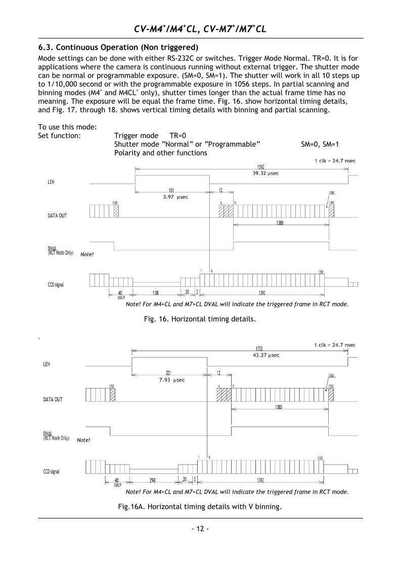
6.3. Continuous Operation (Non triggered) Mode settings can be done with either RS-232C or switches. Trigger Mode Normal. TR=0. It is for applications where the camera is continuous running without external trigger. The shutter mode can be normal or programmable exposure. (SM=0, SM=1). The shutter will work in all 10 steps up to 1/10,000 second or with the programmable exposure in 1056 steps. In partial scanning and binning modes (M4+ and M4CL+ only), shutter times longer than the actual frame time has no meaning. The exposure will be equal the frame time. Fig. 16. show horizontal timing details, and Fig. 17. through 18. shows vertical timing details with binning and partial scanning. To use this mode: Set function: Trigger mode TR=0 Shutter mode “Normal” or “Programmable” SM=0, SM=1 Polarity and other functions
.
Note!
Note! For M4+CL and M7+CL DVAL will indicate the triggered frame in RCT mode.
Fig. 16. Horizontal timing details.
Note!
Note! For M4+CL and M7+CL DVAL will indicate the triggered frame in RCT mode.
Fig.16A. Horizontal timing details with V binning.
- 12 -
CV-M4+/M4+CL, CV-M7+/M7+CL
- 13 -
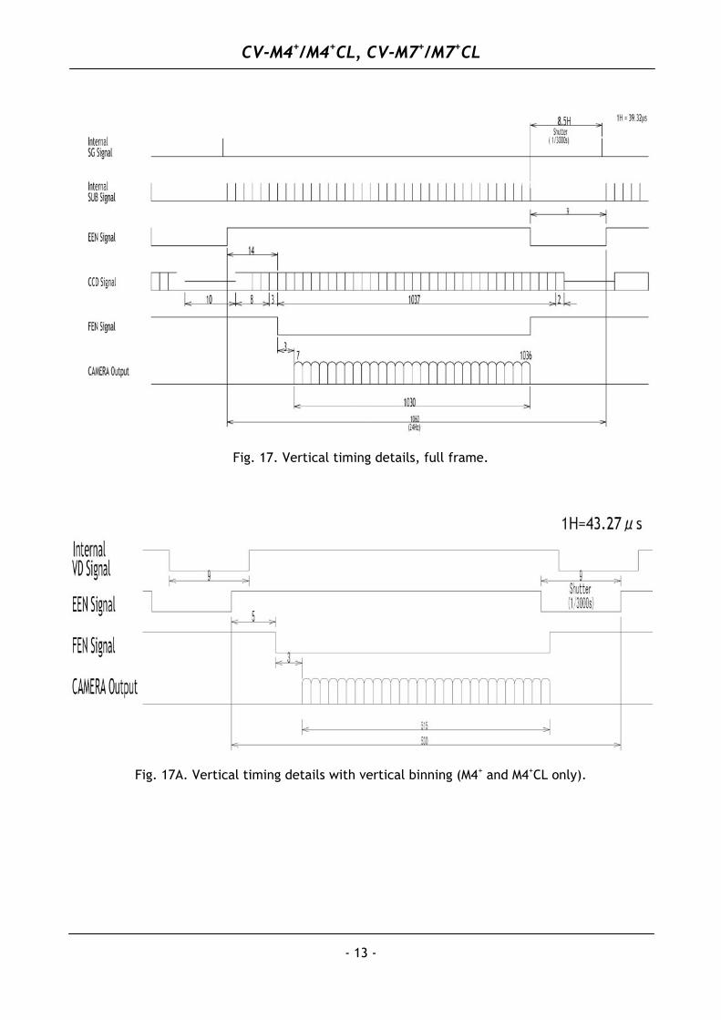
Fig. 17. Vertical timing details, full frame.
Fig. 17A. Vertical timing details with vertical binning (M4+ and M4+CL only).
CV-M4+/M4+CL, CV-M7+/M7+CL
- 14 -
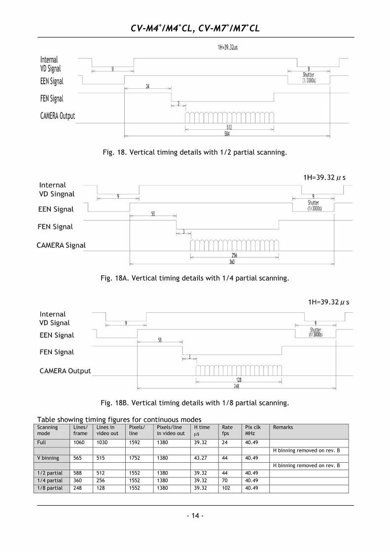
Fig. 18. Vertical timing details with 1/2 partial scanning.
Fig. 18A. Vertical timing details with 1/4 partial scanning.
Fig. 18B. Vertical timing details with 1/8 partial scanning.
Table showing timing figures for continuous modes Scanning mode
Lines/ frame
Lines in video out
Pixels/ line
Pixels/line in video out
H time µs
Rate fps
Pix clk MHz
Remarks
Full 1060 1030 1592 1380 39.32 24 40.49
H binning removed on rev. B V binning 565 515 1752 1380 43.27 44 40.49 H binning removed on rev. B 1/2 partial 588 512 1552 1380 39.32 44 40.49 1/4 partial 360 256 1552 1380 39.32 70 40.49 1/8 partial 248 128 1552 1380 39.32 102 40.49
CV-M4+/M4+CL, CV-M7+/M7+CL
- 15 -
6.4. External Trigger Modes This camera has 3 external asynchronous trigger modes, which can be set by RS-232C commands or switches.
1. Edge Pre-select Mode. TR=1 Pre-selected exposure. (SM=0, SM=1) 2. Pulse Width Control Mode. TR=2 Pulse width controlled exposure. 3. Frame Delay read out mode. TR=3 Pre-select exp. Read out by trailing trig. edge.
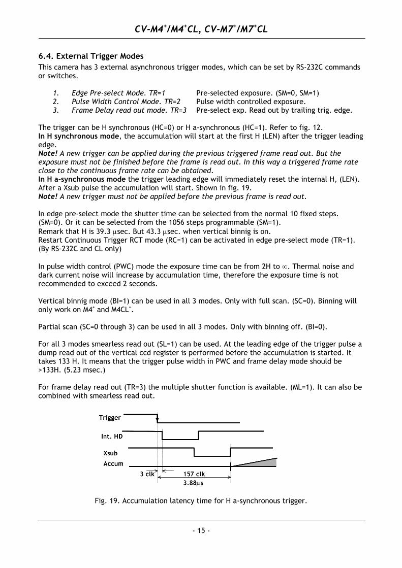
The trigger can be H synchronous (HC=0) or H a-synchronous (HC=1). Refer to fig. 12. In H synchronous mode, the accumulation will start at the first H (LEN) after the trigger leading edge. Note! A new trigger can be applied during the previous triggered frame read out. But the exposure must not be finished before the frame is read out. In this way a triggered frame rate close to the continuous frame rate can be obtained. In H a-synchronous mode the trigger leading edge will immediately reset the internal H, (LEN). After a Xsub pulse the accumulation will start. Shown in fig. 19. Note! A new trigger must not be applied before the previous frame is read out. In edge pre-select mode the shutter time can be selected from the normal 10 fixed steps. (SM=0). Or it can be selected from the 1056 steps programmable (SM=1). Remark that H is 39.3 µsec. But 43.3 µsec. when vertical binnig is on. Restart Continuous Trigger RCT mode (RC=1) can be activated in edge pre-select mode (TR=1). (By RS-232C and CL only) In pulse width control (PWC) mode the exposure time can be from 2H to ∞. Thermal noise and dark current noise will increase by accumulation time, therefore the exposure time is not recommended to exceed 2 seconds. Vertical binnig mode (BI=1) can be used in all 3 modes. Only with full scan. (SC=0). Binning will only work on M4+ and M4CL+. Partial scan (SC=0 through 3) can be used in all 3 modes. Only with binning off. (BI=0). For all 3 modes smearless read out (SL=1) can be used. At the leading edge of the trigger pulse a dump read out of the vertical ccd register is performed before the accumulation is started. It takes 133 H. It means that the trigger pulse width in PWC and frame delay mode should be >133H. (5.23 msec.) For frame delay read out (TR=3) the multiple shutter function is available. (ML=1). It can also be combined with smearless read out.
Xsub
Accum
Int. HD
Trigger
157 clk3.88µs
3 clk
Xsub
Accum
Int. HD
Trigger
Xsub
Accum
Int. HD
Trigger
157 clk3.88µs
3 clk
Fig. 19. Accumulation latency time for H a-synchronous trigger.
CV-M4+/M4+CL, CV-M7+/M7+CL
- 16 -
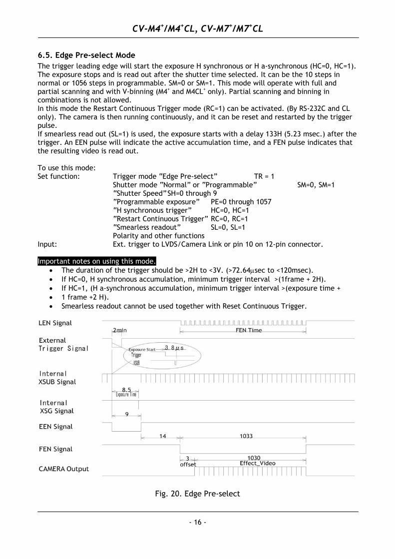
6.5. Edge Pre-select Mode The trigger leading edge will start the exposure H synchronous or H a-synchronous (HC=0, HC=1). The exposure stops and is read out after the shutter time selected. It can be the 10 steps in normal or 1056 steps in programmable. SM=0 or SM=1. This mode will operate with full and partial scanning and with V-binning (M4+ and M4CL+ only). Partial scanning and binning in combinations is not allowed. In this mode the Restart Continuous Trigger mode (RC=1) can be activated. (By RS-232C and CL only). The camera is then running continuously, and it can be reset and restarted by the trigger pulse. If smearless read out (SL=1) is used, the exposure starts with a delay 133H (5.23 msec.) after the trigger. An EEN pulse will indicate the active accumulation time, and a FEN pulse indicates that the resulting video is read out. To use this mode: Set function: Trigger mode “Edge Pre-select” TR = 1 Shutter mode “Normal” or “Programmable” SM=0, SM=1 “Shutter Speed” SH=0 through 9 “Programmable exposure” PE=0 through 1057 “H synchronous trigger” HC=0, HC=1 “Restart Continuous Trigger” RC=0, RC=1 “Smearless readout” SL=0, SL=1 Polarity and other functions Input: Ext. trigger to LVDS/Camera Link or pin 10 on 12-pin connector. Important notes on using this mode.
• The duration of the trigger should be >2H to <3V. (>72.64µsec to <120msec). • If HC=0, H synchronous accumulation, minimum trigger interval >(1frame + 2H). • If HC=1, (H a-synchronous accumulation, minimum trigger interval >(exposure time + • 1 frame +2 H). • Smearless readout cannot be used together with Reset Continuous Trigger.
Fig. 20. Edge Pre-select
CV-M4+/M4+CL, CV-M7+/M7+CL
- 17 -
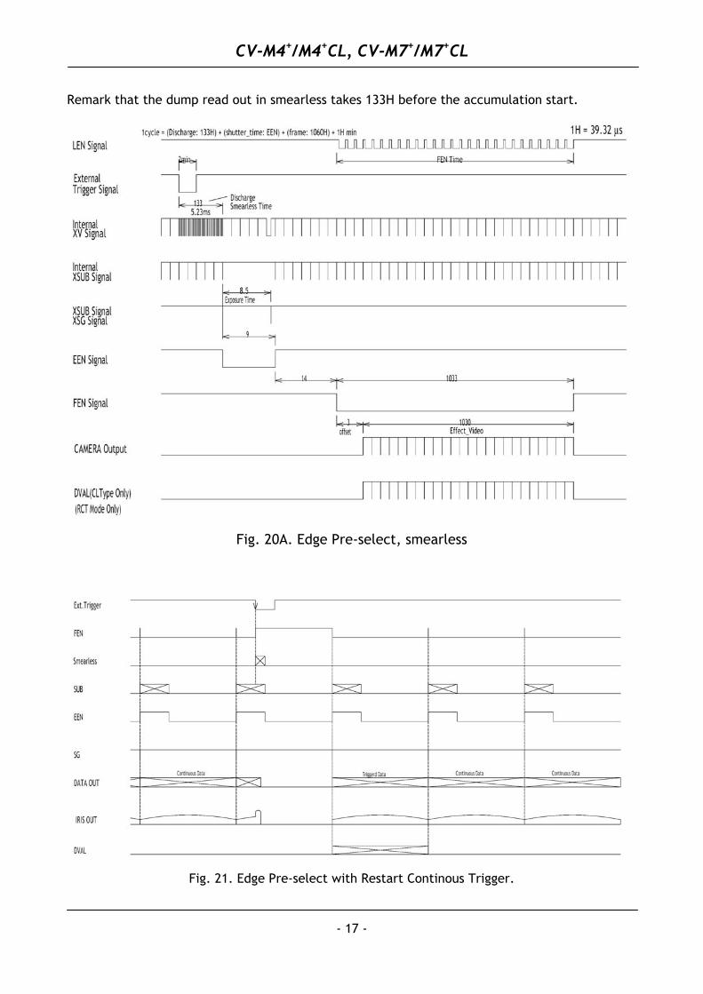
Remark that the dump read out in smearless takes 133H before the accumulation start.
Fig. 20A. Edge Pre-select, smearless
Fig. 21. Edge Pre-select with Restart Continous Trigger.
CV-M4+/M4+CL, CV-M7+/M7+CL
- 18 -
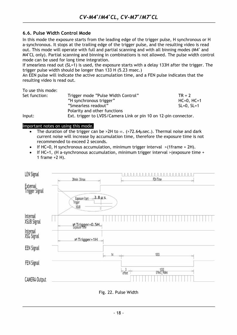
6.6. Pulse Width Control Mode In this mode the exposure starts from the leading edge of the trigger pulse, H synchronous or H a-synchronous. It stops at the trailing edge of the trigger pulse, and the resulting video is read out. This mode will operate with full and partial scanning and with all binning modes (M4+ and M4+CL only). Partial scanning and binning in combinations is not allowed. The pulse width control mode can be used for long time integration. If smearless read out (SL=1) is used, the exposure starts with a delay 133H after the trigger. The trigger pulse width should be longer than 133 H (5.23 msec.) An EEN pulse will indicate the active accumulation time, and a FEN pulse indicates that the resulting video is read out. To use this mode: Set function: Trigger mode “Pulse Width Control” TR = 2 “H synchronous trigger” HC=0, HC=1 “Smearless readout” SL=0, SL=1 Polarity and other functions Input: Ext. trigger to LVDS/Camera Link or pin 10 on 12-pin connector. Important notes on using this mode.
• The duration of the trigger can be >2H to ∞. (>72.64µsec.). Thermal noise and dark current noise will increase by accumulation time, therefore the exposure time is not recommended to exceed 2 seconds.
• If HC=0, H synchronous accumulation, minimum trigger interval >(1frame + 2H). • If HC=1, (H a-synchronous accumulation, minimum trigger interval >(exposure time +
1 frame +2 H).
Fig. 22. Pulse Width
CV-M4+/M4+CL, CV-M7+/M7+CL
- 19 -
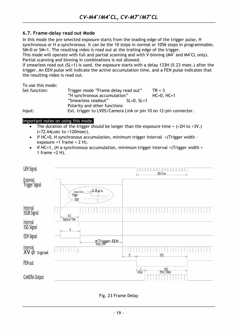
6.7. Frame-delay read out Mode In this mode the pre selected exposure starts from the leading edge of the trigger pulse, H synchronous or H a-synchronous. It can be the 10 steps in normal or 1056 steps in programmable. SM=0 or SM=1. The resulting video is read out at the trailing edge of the trigger. This mode will operate with full and partial scanning and with V binning (M4+ and M4+CL only). Partial scanning and binning in combinations is not allowed. If smearless read out (SL=1) is used, the exposure starts with a delay 133H (5.23 msec.) after the trigger. An EEN pulse will indicate the active accumulation time, and a FEN pulse indicates that the resulting video is read out. To use this mode: Set function: Trigger mode “Frame delay read out” TR = 3 “H synchronous accumulation” HC=0, HC=1 “Smearless readout” SL=0, SL=1 Polarity and other functions Input: Ext. trigger to LVDS/Camera Link or pin 10 on 12-pin connector. Important notes on using this mode.
• The duration of the trigger should be longer than the exposure time + (>2H to <3V.) (>72.64µsec to <120msec).
• If HC=0, H synchronous accumulation, minimum trigger interval >(Trigger width – exposure +1 frame + 2 H).
• If HC=1, (H a-synchronous accumulation, minimum trigger interval >(Trigger width + 1 frame +2 H).
Fig. 23 Frame Delay
CV-M4+/M4+CL, CV-M7+/M7+CL
- 20 -
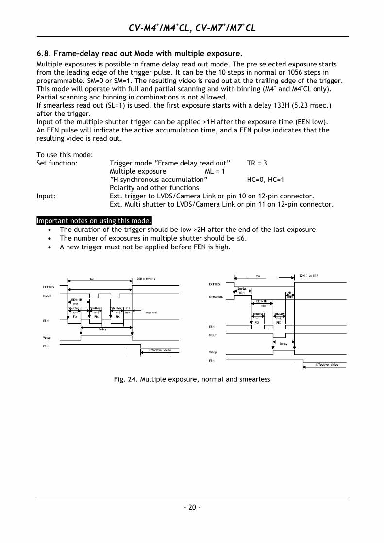
6.8. Frame-delay read out Mode with multiple exposure. Multiple exposures is possible in frame delay read out mode. The pre selected exposure starts from the leading edge of the trigger pulse. It can be the 10 steps in normal or 1056 steps in programmable. SM=0 or SM=1. The resulting video is read out at the trailing edge of the trigger. This mode will operate with full and partial scanning and with binning (M4+ and M4+CL only). Partial scanning and binning in combinations is not allowed. If smearless read out (SL=1) is used, the first exposure starts with a delay 133H (5.23 msec.) after the trigger. Input of the multiple shutter trigger can be applied >1H after the exposure time (EEN low). An EEN pulse will indicate the active accumulation time, and a FEN pulse indicates that the resulting video is read out. To use this mode: Set function: Trigger mode “Frame delay read out” TR = 3 Multiple exposure ML = 1 “H synchronous accumulation” HC=0, HC=1 Polarity and other functions Input: Ext. trigger to LVDS/Camera Link or pin 10 on 12-pin connector. Ext. Multi shutter to LVDS/Camera Link or pin 11 on 12-pin connector. Important notes on using this mode.
• The duration of the trigger should be low >2H after the end of the last exposure. • The number of exposures in multiple shutter should be ≤6. • A new trigger must not be applied before FEN is high.
Fig. 24. Multiple exposure, normal and smearless
CV-M4+/M4+CL, CV-M7+/M7+CL
- 21 -
6.9. Other Functions. Functions which can be controlled by either RS-232C or switches, or both. Gain and set-up. !! Do not adjust these settings unless you have knowledge to video adjustments!! The video gain is set to manual. In manual gain mode, either the gain level (GA) or the rear potentiometer (RP). can adjust the level. Set-up level. (SU). This setting can adjust the set-up level (or black level). Vertical Binning (BI). Only vertical binning is possible. It can be selected by the command BI=1, or by the internal switch SW301-6. (Off 0 normal, ON = V-binnig.) Binning is only for CV-M4+ and M4+CL. When binning is active, the horizontal time H is changed from 39.3 µsec. to 43.3 µsec. It will result in longer exposure times in Edge Pre-Select shutter mode PE. SYNC/EEN output. (SE). Will select SYNC or EEN signal output on pin #9 on 12-pin connector. Trigger polarity. (TP). Will invert the trigger-input signal. LEN/FEN/EEN polarity. (FP). Will invert the LEN, FEN and EEN output signal. Important notes on using this functions. • Do not attempt to adjust the set-up level without knowledge to it. • Do not attempt to use ASCII commands not shown in “7.5. CV-M4+ command list.”
CV-M4+/M4+CL, CV-M7+/M7+CL
- 22 -
7. Configuring the Camera
7.1. Mode setting SW1 on rear
seco
nds
OFF ON12345678
CONTROL
SHUTTER
SCANNING
< < > > < > < >
< >
Normal < >
Local RS232C
Smear-less
<<<
<<<
<<>
<<>
<><
<><
<>>
<>>
1/24
1/50
1/10
0
1/20
01/
400
1/80
0
1/15
001/
3000
< > < > < > < >
><<
><<
1/50
001/
10,0
00
< >
EXT.TRIGGER
Off
Edg
epr
e se
l.
Pul
sew
idth
Fram
ede
lay
109SMEAR-LESS
< < > > < > < > Fu
ll
1/2
part.
1/4
part.
1/8
part.
Rear SW
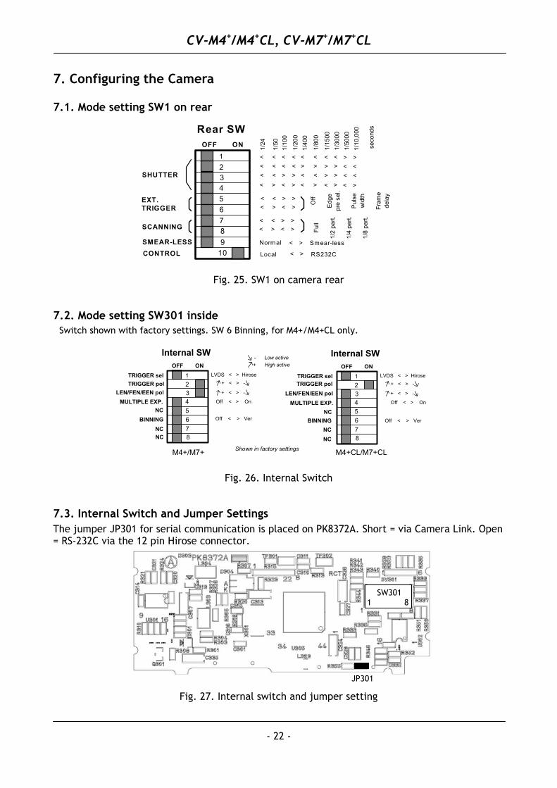
Fig. 25. SW1 on camera rear
7.2. Mode setting SW301 inside Switch shown with factory settings. SW 6 Binning, for M4+/M4+CL only.
+ High active- Low active
M4+CL/M7+CL
OFF ON12345678
LVDS < > Hirose
Internal SW
TRIGGER selTRIGGER pol
LEN/FEN/EEN polMULTIPLE EXP. Off < > On
+ < > -
BINNING
+ < > -
NC
NCNC
Off < > Ver
M4+/M7+
LEN/FEN/EEN polMULTIPLE EXP.
OFF ON12345678
Off < > Ver
LVDS < > Hirose
Internal SW
Off < > On
+ < > -
BINNING
+ < > -
NC
NC
NC
TRIGGER selTRIGGER pol
Shown in factory settings
Fig. 26. Internal Switch
7.3. Internal Switch and Jumper Settings The jumper JP301 for serial communication is placed on PK8372A. Short = via Camera Link. Open = RS-232C via the 12 pin Hirose connector.
JP301
SW301 1 8
Fig. 27. Internal switch and jumper setting
CV-M4+/M4+CL, CV-M7+/M7+CL
- 23 -
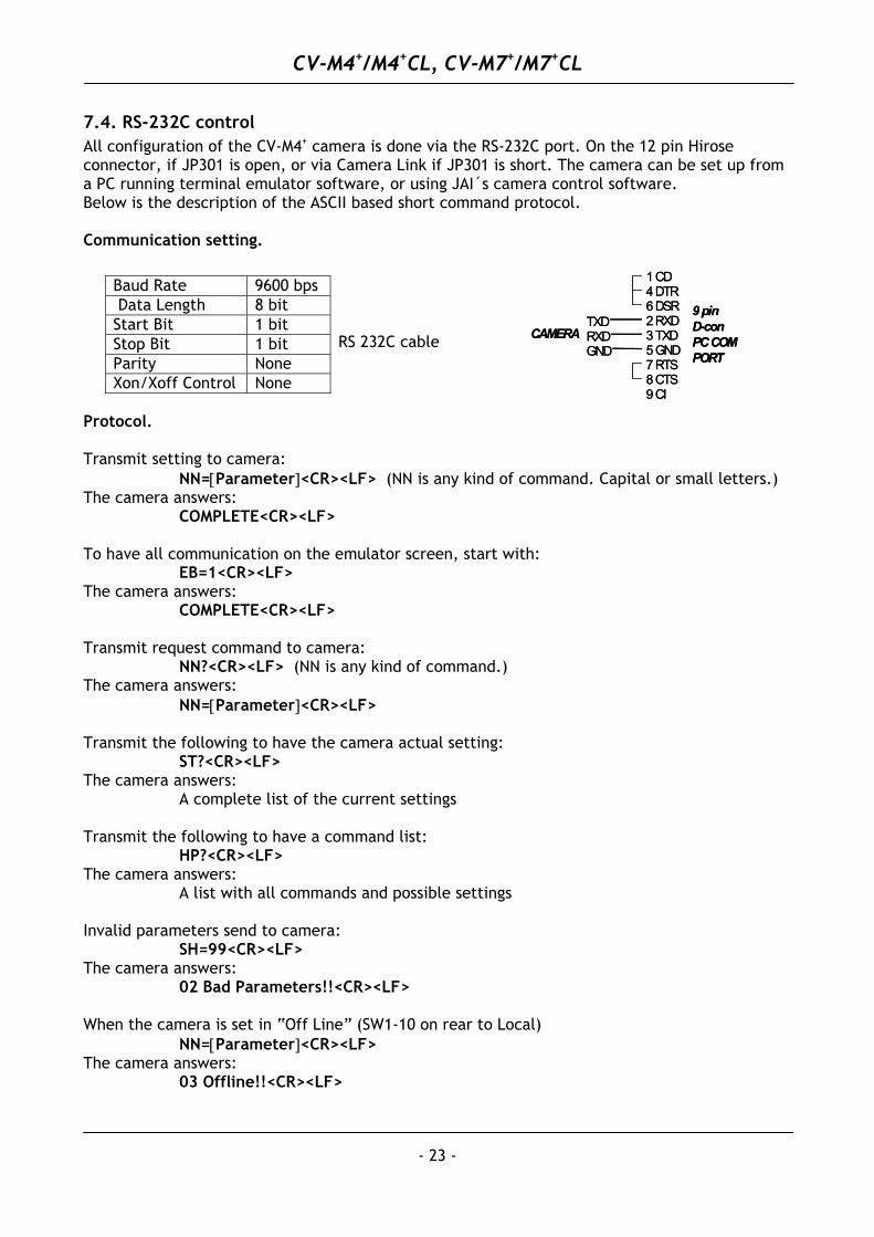
7.4. RS-232C control All configuration of the CV-M4+ camera is done via the RS-232C port. On the 12 pin Hirose connector, if JP301 is open, or via Camera Link if JP301 is short. The camera can be set up from a PC running terminal emulator software, or using JAI´s camera control software. Below is the description of the ASCII based short command protocol. Communication setting.
TXDRXDGND
1 CD4 DTR6 DSR2 RXD3 TXD5 GND7 RTS8 CTS9 CI
9 pinD-conPC COMPORT
CAMERATXDRXDGND
1 CD4 DTR6 DSR2 RXD3 TXD5 GND7 RTS8 CTS9 CI
9 pinD-conPC COMPORT
CAMERA
Baud Rate 9600 bps Data Length 8 bit Start Bit 1 bit Stop Bit 1 bit Parity None Xon/Xoff Control None
RS 232C cable
Protocol. Transmit setting to camera:
NN=[Parameter]<CR><LF> (NN is any kind of command. Capital or small letters.) The camera answers:
COMPLETE<CR><LF> To have all communication on the emulator screen, start with: EB=1<CR><LF> The camera answers:
COMPLETE<CR><LF> Transmit request command to camera:
NN?<CR><LF> (NN is any kind of command.) The camera answers:
NN=[Parameter]<CR><LF> Transmit the following to have the camera actual setting:
ST?<CR><LF> The camera answers:
A complete list of the current settings Transmit the following to have a command list:
HP?<CR><LF> The camera answers:
A list with all commands and possible settings Invalid parameters send to camera:
SH=99<CR><LF> The camera answers:
02 Bad Parameters!!<CR><LF> When the camera is set in “Off Line” (SW1-10 on rear to Local) NN=[Parameter]<CR><LF> The camera answers:
03 Offline!!<CR><LF>
CV-M4+/M4+CL, CV-M7+/M7+CL
- 24 -
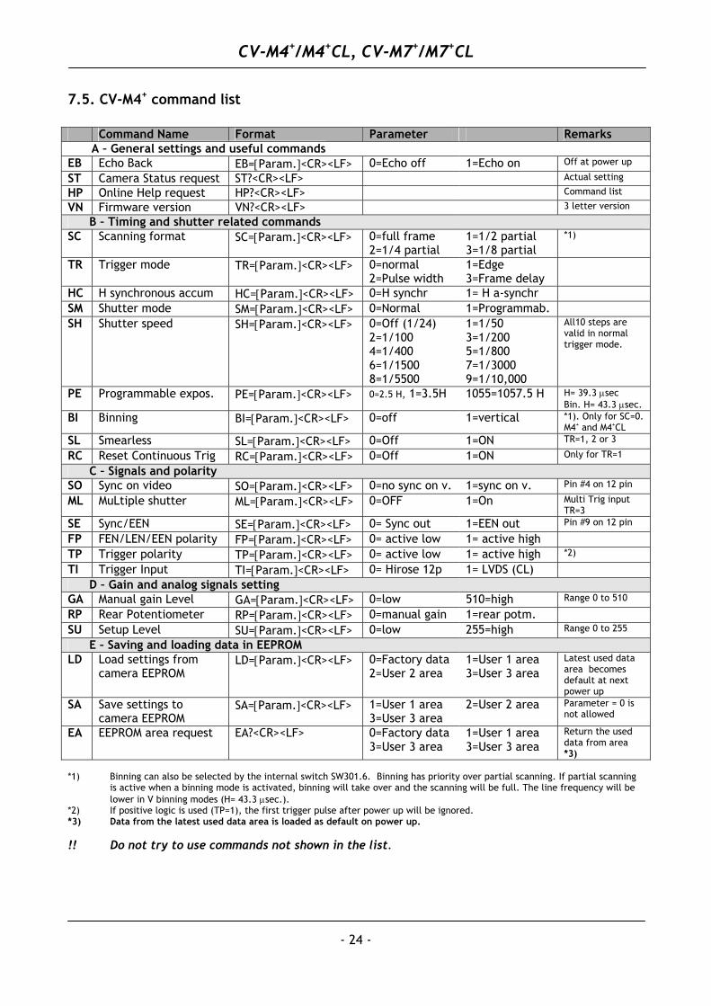
7.5. CV-M4+ command list Command Name Format Parameter Remarks A – General settings and useful commands EB Echo Back EB=[Param.]<CR><LF> 0=Echo off 1=Echo on Off at power up
ST Camera Status request ST?<CR><LF> Actual setting
HP Online Help request HP?<CR><LF> Command list
VN Firmware version VN?<CR><LF> 3 letter version
B – Timing and shutter related commands SC Scanning format SC=[Param.]<CR><LF> 0=full frame
2=1/4 partial 1=1/2 partial 3=1/8 partial
*1)
TR Trigger mode TR=[Param.]<CR><LF> 0=normal 2=Pulse width
1=Edge 3=Frame delay
HC H synchronous accum HC=[Param.]<CR><LF> 0=H synchr 1= H a-synchr SM Shutter mode SM=[Param.]<CR><LF> 0=Normal 1=Programmab. SH Shutter speed SH=[Param.]<CR><LF> 0=Off (1/24)
2=1/100 4=1/400 6=1/1500 8=1/5500
1=1/50 3=1/200 5=1/800 7=1/3000 9=1/10,000
All10 steps are valid in normal trigger mode.
PE Programmable expos. PE=[Param.]<CR><LF> 0=2.5 H, 1=3.5H 1055=1057.5 H H= 39.3 µsec Bin. H= 43.3 µsec.
BI Binning BI=[Param.]<CR><LF> 0=off 1=vertical *1). Only for SC=0. M4+ and M4+CL
SL Smearless SL=[Param.]<CR><LF> 0=Off 1=ON TR=1, 2 or 3
RC Reset Continuous Trig RC=[Param.]<CR><LF> 0=Off 1=ON Only for TR=1
C – Signals and polarity SO Sync on video SO=[Param.]<CR><LF> 0=no sync on v. 1=sync on v. Pin #4 on 12 pin ML MuLtiple shutter ML=[Param.]<CR><LF> 0=OFF 1=On Multi Trig input
TR=3 SE Sync/EEN SE=[Param.]<CR><LF> 0= Sync out 1=EEN out Pin #9 on 12 pin
FP FEN/LEN/EEN polarity FP=[Param.]<CR><LF> 0= active low 1= active high
TP Trigger polarity TP=[Param.]<CR><LF> 0= active low 1= active high *2)
TI Trigger Input TI=[Param.]<CR><LF> 0= Hirose 12p 1= LVDS (CL) D – Gain and analog signals setting GA Manual gain Level GA=[Param.]<CR><LF> 0=low 510=high Range 0 to 510
RP Rear Potentiometer RP=[Param.]<CR><LF> 0=manual gain 1=rear potm.
SU Setup Level SU=[Param.]<CR><LF> 0=low 255=high Range 0 to 255
E – Saving and loading data in EEPROM LD Load settings from
camera EEPROM LD=[Param.]<CR><LF> 0=Factory data
2=User 2 area 1=User 1 area 3=User 3 area
Latest used data area becomes default at next power up
SA Save settings to camera EEPROM
SA=[Param.]<CR><LF> 1=User 1 area 3=User 3 area
2=User 2 area Parameter = 0 is not allowed
EA EEPROM area request EA?<CR><LF> 0=Factory data 3=User 3 area
1=User 1 area 3=User 3 area
Return the used data from area *3)
*1) Binning can also be selected by the internal switch SW301.6. Binning has priority over partial scanning. If partial scanning
is active when a binning mode is activated, binning will take over and the scanning will be full. The line frequency will be lower in V binning modes (H= 43.3 µsec.).
*2) If positive logic is used (TP=1), the first trigger pulse after power up will be ignored. *3) Data from the latest used data area is loaded as default on power up. !! Do not try to use commands not shown in the list.
CV-M4+/M4+CL, CV-M7+/M7+CL
- 25 -
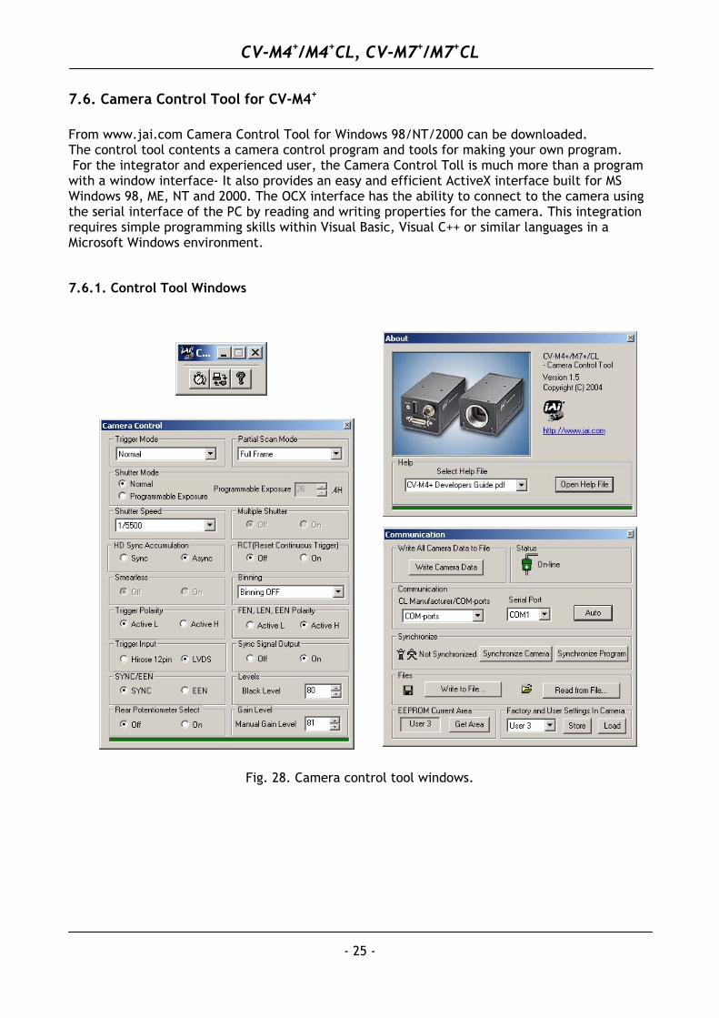
7.6. Camera Control Tool for CV-M4+
From www.jai.com Camera Control Tool for Windows 98/NT/2000 can be downloaded. The control tool contents a camera control program and tools for making your own program. For the integrator and experienced user, the Camera Control Toll is much more than a program with a window interface- It also provides an easy and efficient ActiveX interface built for MS Windows 98, ME, NT and 2000. The OCX interface has the ability to connect to the camera using the serial interface of the PC by reading and writing properties for the camera. This integration requires simple programming skills within Visual Basic, Visual C++ or similar languages in a Microsoft Windows environment.
7.6.1. Control Tool Windows
Fig. 28. Camera control tool windows.
CV-M4+/M4+CL, CV-M7+/M7+CL
- 26 -
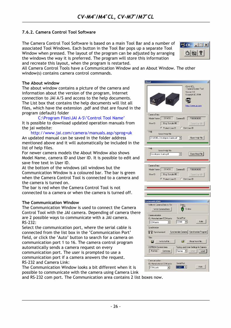
7.6.2. Camera Control Tool Software The Camera Control Tool Software is based on a main Tool Bar and a number of associated Tool Windows. Each button in the Tool Bar pops up a separate Tool Window when pressed. The layout of the program can be adjusted by arranging the windows the way it is preferred. The program will store this information and recreate this layout, when the program is restarted. All Camera Control Tools have a Communication Window and an About Window. The other window(s) contains camera control commands. The About window The about window contains a picture of the camera and information about the version of the program, Internet connection to JAI A/S and access to the help documents. The List box that contains the help documents will list all files, which have the extension .pdf and that are found in the program (default) folder
C:\Program Files\JAI A-S\’Control Tool Name’ It is possible to download updated operation manuals from the jai website:
http://www.jai.com/camera/manuals.asp/sprog=uk An updated manual can be saved in the folder address mentioned above and it will automatically be included in the list of help files. For newer camera models the About Window also shows Model Name, camera ID and User ID. It is possible to edit and save free text in User ID. At the bottom of the windows (all windows but the Communication Window is a coloured bar. The bar is green when the Camera Control Tool is connected to a camera and the camera is turned on. The bar is red when the Camera Control Tool is not connected to a camera or when the camera is turned off. The Communication Window The Communication Window is used to connect the Camera Control Tool with the JAI camera. Depending of camera there are 2 possible ways to communicate with a JAI camera. RS-232: Select the communication port, where the serial cable is connected from the list box in the ‘Communication Port’ field, or click the ‘Auto’ button to search for a camera on communication port 1 to 16. The camera control program automatically sends a camera request on every communication port. The user is prompted to use a communication port if a camera answers the request. RS-232 and Camera Link: The Communication Window looks a bit different when it is possible to communicate with the camera using Camera Link and RS-232 com port. The Communication area contains 2 list boxes now.
CV-M4+/M4+CL, CV-M7+/M7+CL
- 27 -
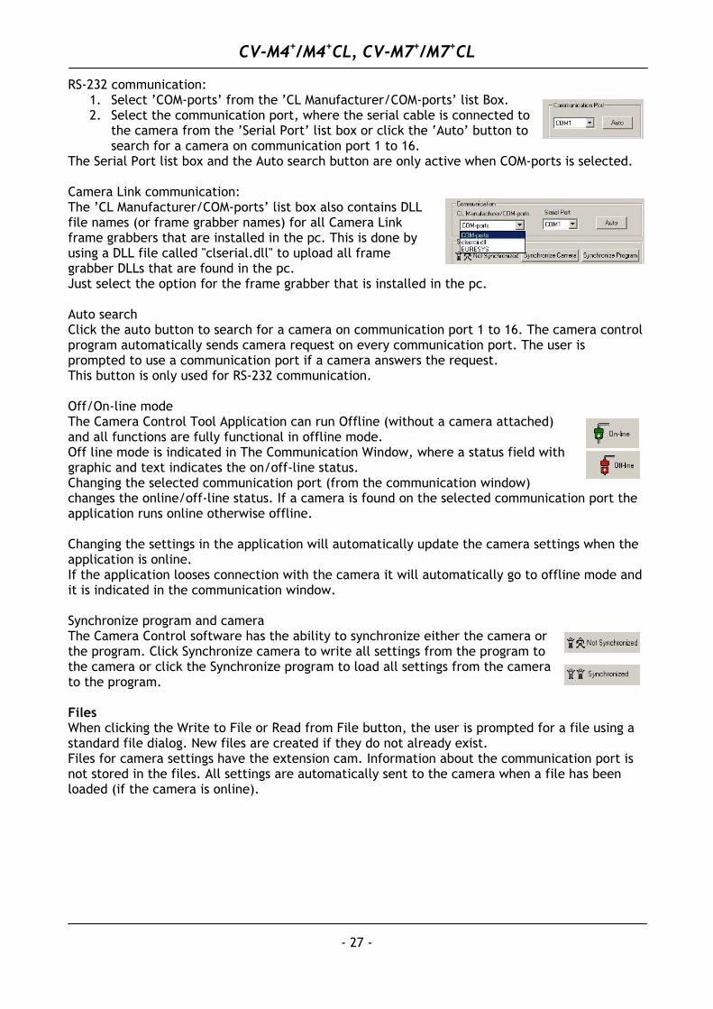
RS-232 communication:
1. Select ’COM-ports’ from the ’CL Manufacturer/COM-ports’ list Box. 2. Select the communication port, where the serial cable is connected to
the camera from the ’Serial Port’ list box or click the ‘Auto’ button to search for a camera on communication port 1 to 16.
The Serial Port list box and the Auto search button are only active when COM-ports is selected. Camera Link communication: The ’CL Manufacturer/COM-ports’ list box also contains DLL file names (or frame grabber names) for all Camera Link frame grabbers that are installed in the pc. This is done by using a DLL file called "clserial.dll" to upload all frame grabber DLLs that are found in the pc. Just select the option for the frame grabber that is installed in the pc. Auto search Click the auto button to search for a camera on communication port 1 to 16. The camera control program automatically sends camera request on every communication port. The user is prompted to use a communication port if a camera answers the request. This button is only used for RS-232 communication. Off/On-line mode The Camera Control Tool Application can run Offline (without a camera attached) and all functions are fully functional in offline mode. Off line mode is indicated in The Communication Window, where a status field with graphic and text indicates the on/off-line status. Changing the selected communication port (from the communication window) changes the online/off-line status. If a camera is found on the selected communication port the application runs online otherwise offline. Changing the settings in the application will automatically update the camera settings when the application is online. If the application looses connection with the camera it will automatically go to offline mode and it is indicated in the communication window. Synchronize program and camera The Camera Control software has the ability to synchronize either the camera or the program. Click Synchronize camera to write all settings from the program to the camera or click the Synchronize program to load all settings from the camera to the program. Files When clicking the Write to File or Read from File button, the user is prompted for a file using a standard file dialog. New files are created if they do not already exist. Files for camera settings have the extension cam. Information about the communication port is not stored in the files. All settings are automatically sent to the camera when a file has been loaded (if the camera is online).
CV-M4+/M4+CL, CV-M7+/M7+CL
- 28 -
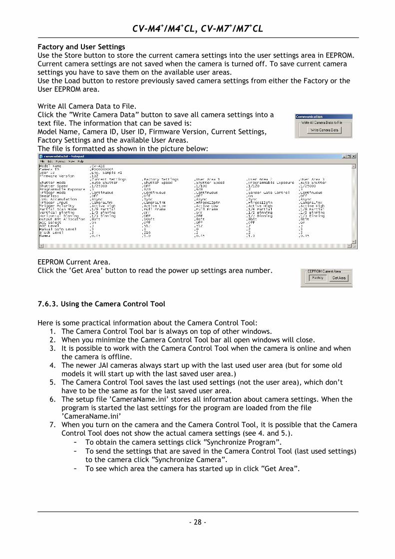
Factory and User Settings Use the Store button to store the current camera settings into the user settings area in EEPROM. Current camera settings are not saved when the camera is turned off. To save current camera settings you have to save them on the available user areas. Use the Load button to restore previously saved camera settings from either the Factory or the User EEPROM area. Write All Camera Data to File. Click the “Write Camera Data” button to save all camera settings into a text file. The information that can be saved is: Model Name, Camera ID, User ID, Firmware Version, Current Settings, Factory Settings and the available User Areas. The file is formatted as shown in the picture below:
EEPROM Current Area. Click the ‘Get Area’ button to read the power up settings area number.
7.6.3. Using the Camera Control Tool Here is some practical information about the Camera Control Tool:
1. The Camera Control Tool bar is always on top of other windows. 2. When you minimize the Camera Control Tool bar all open windows will close. 3. It is possible to work with the Camera Control Tool when the camera is online and when
the camera is offline. 4. The newer JAI cameras always start up with the last used user area (but for some old
models it will start up with the last saved user area.) 5. The Camera Control Tool saves the last used settings (not the user area), which don’t
have to be the same as for the last saved user area. 6. The setup file ’CameraName.ini’ stores all information about camera settings. When the
program is started the last settings for the program are loaded from the file ’CameraName.ini’
7. When you turn on the camera and the Camera Control Tool, it is possible that the Camera Control Tool does not show the actual camera settings (see 4. and 5.).
- To obtain the camera settings click “Synchronize Program”. - To send the settings that are saved in the Camera Control Tool (last used settings)
to the camera click “Synchronize Camera”. - To see which area the camera has started up in click “Get Area”.
CV-M4+/M4+CL, CV-M7+/M7+CL
- 29 -
8. External Appearance and Dimensions
Fig. 29. Outline
9. Specifications
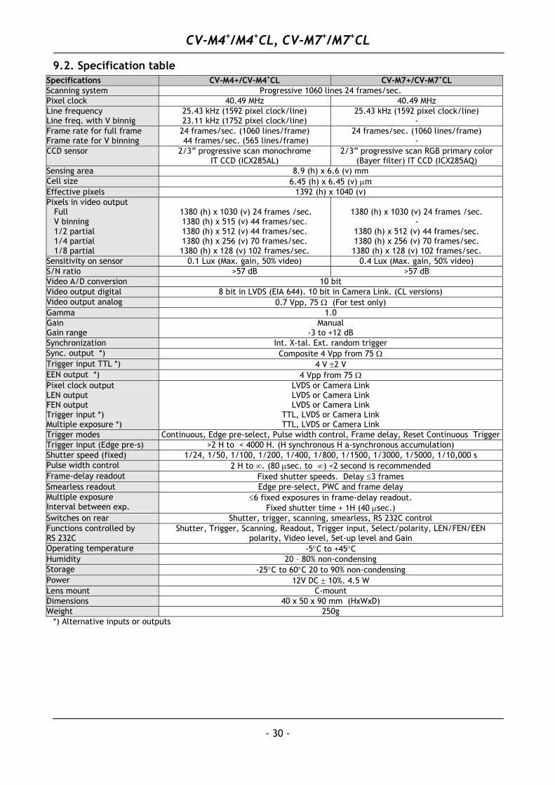
9.1. Spectral sensitivity CV-M7+ and M7+Cl are with an IR stop and optical low-pass filter block in front of the CCD sensor.
400 500 600 700 800 900Wave lenght (nm)
1.0
0.8
0.6
0.4
0.2
0.0
Rel
ativ
e re
spon
se
1000
Wave length (nm)400 500 600 700 8 00
1.0
0 .8
0 .6
0 .4
0 .2
0 .0
Rela
tive
resp
onse IR stop
B G R
Wave length (nm)400 500 600 700 8 00
1.0
0 .8
0 .6
0 .4
0 .2
0 .0
Rela
tive
resp
onse IR stop
B G R
Fig. 30. Spectral sensitivity for M4+/M4+CL Fig. 31. Spectral sensitivity for M7+/M7+CL
CV-M4+/M4+CL, CV-M7+/M7+CL
9.2. Specification table Specifications CV-M4+/CV-M4+CL CV-M7+/CV-M7+CL Scanning system Progressive 1060 lines 24 frames/sec. Pixel clock 40.49 MHz 40.49 MHz Line frequency Line freq. with V binnig
25.43 kHz (1592 pixel clock/line) 23.11 kHz (1752 pixel clock/line)
25.43 kHz (1592 pixel clock/line) -
Frame rate for full frame Frame rate for V binning
24 frames/sec. (1060 lines/frame) 44 frames/sec. (565 lines/frame)
24 frames/sec. (1060 lines/frame) -
CCD sensor 2/3” progressive scan monochrome IT CCD (ICX285AL)
2/3” progressive scan RGB primary color (Bayer filter) IT CCD (ICX285AQ)
Sensing area 8.9 (h) x 6.6 (v) mm Cell size 6.45 (h) x 6.45 (v) µm Effective pixels 1392 (h) x 1040 (v) Pixels in video output Full V binning 1/2 partial 1/4 partial 1/8 partial
1380 (h) x 1030 (v) 24 frames /sec. 1380 (h) x 515 (v) 44 frames/sec. 1380 (h) x 512 (v) 44 frames/sec. 1380 (h) x 256 (v) 70 frames/sec. 1380 (h) x 128 (v) 102 frames/sec.
1380 (h) x 1030 (v) 24 frames /sec.
- 1380 (h) x 512 (v) 44 frames/sec. 1380 (h) x 256 (v) 70 frames/sec. 1380 (h) x 128 (v) 102 frames/sec.
Sensitivity on sensor 0.1 Lux (Max. gain, 50% video) 0.4 Lux (Max. gain, 50% video) S/N ratio >57 dB >57 dB Video A/D conversion 10 bit Video output digital 8 bit in LVDS (EIA 644). 10 bit in Camera Link. (CL versions) Video output analog 0.7 Vpp, 75 Ω (For test only) Gamma 1.0 Gain Gain range
Manual -3 to +12 dB
Synchronization Int. X-tal. Ext. random trigger Sync. output *) Composite 4 Vpp from 75 Ω Trigger input TTL *) 4 V ±2 V EEN output *) 4 Vpp from 75 Ω Pixel clock output LEN output FEN output Trigger input *) Multiple exposure *)
LVDS or Camera Link LVDS or Camera Link LVDS or Camera Link
TTL, LVDS or Camera Link TTL, LVDS or Camera Link
Trigger modes Continuous, Edge pre-select, Pulse width control, Frame delay, Reset Continuous Trigger Trigger input (Edge pre-s) >2 H to < 4000 H. (H synchronous H a-synchronous accumulation) Shutter speed (fixed) 1/24, 1/50, 1/100, 1/200, 1/400, 1/800, 1/1500, 1/3000, 1/5000, 1/10,000 s Pulse width control 2 H to ∞. (80 µsec. to ∞) <2 second is recommended Frame-delay readout Fixed shutter speeds. Delay ≤3 frames Smearless readout Edge pre-select, PWC and frame delay Multiple exposure Interval between exp.
≤6 fixed exposures in frame-delay readout. Fixed shutter time + 1H (40 µsec.)
Switches on rear Shutter, trigger, scanning, smearless, RS 232C control Functions controlled by RS 232C
Shutter, Trigger, Scanning, Readout, Trigger input, Select/polarity, LEN/FEN/EEN polarity, Video level, Set-up level and Gain
Operating temperature -5°C to +45°C Humidity 20 – 80% non-condensing Storage -25°C to 60°C 20 to 90% non-condensing Power 12V DC ± 10%. 4.5 W Lens mount C-mount Dimensions 40 x 50 x 90 mm (HxWxD) Weight 250g
*) Alternative inputs or outputs
- 30 -
CV-M4+/M4+CL, CV-M7+/M7+CL
- 31 -
10. Appendix
10.1. Precautions Personnel not trained in dealing with similar electronic devices should not service this camera. The camera contains components sensitive to electrostatic discharge. The handling of these devices should follow the requirements of electrostatic sensitive components. Do not attempt to disassemble this camera. Do not expose this camera to rain or moisture. Do not face this camera towards the sun, extreme bright light or light reflecting objects. When this camera is not in use, put the supplied lens cap on the lens mount. Handle this camera with the maximum care. Operate this camera only from the type of power source indicated on the camera. Power off the camera during any modification such as changes of jumper and switch setting.
10.2. Typical CCD Characteristics The following effects may be observed on the video monitor screen. They do not indicate any fault of the CCD camera, but do associate with typical CCD characteristics. V. Smear Due to an excessive bright object such as electric lighting, sun or strong reflection, vertical smear may be visible on the video monitor screen. This phenomenon is related to the characteristics of the Interline Transfer System employed in the CCD. V. Aliasing When the CCD camera captures stripes, straight lines or similar sharp patterns, jagged image on the monitor may appear. Blemishes Some pixel defects can occur, but this does not have en effect on the practical operation. Patterned Noise When the CCD camera captures a dark object at high temperature or is used for long time integration, fixed pattern noise (shown as white dots) may appear on the video monitor screen. Disclaimer Increased dark current (white spots) over time in ExView sensors. It is known that radiation damage increases the dark current of a CCD sensor. This is also true for radiation arising from natural sources, also known as background radiation. These sources include: 1. Terrestrial radiation from naturally occurring radioactive isotopes in the soil. 2. Cosmic radiation originating in outer space. 3. Naturally occurring radioactive isotopes in the body. The ExView series of CCD sensors have greatly improved responsivity, especially in the Near IR part of the spectrum. This greatly improved performance comes at the price of accelerated degradation (increased dark current) due to natural background radiation. This degradation effect is approximately 4 times as fast as in standard sensors, such as Hyper HAD sensors. The degradation effect will manifest itself as in increasing non-uniformity of pixels when viewed in the dark (white spots). This is a natural effect, and is not eligible for warranty replacement/repair of the CCD camera. Exview HAD CCD TM is a trademark of Sony Corporation
CV-M4+/M4+CL, CV-M7+/M7+CL
- 32 -
10.3. References This manual for CV-M4+/M4+CL, M7+/M7+CL can be downloaded from www.jai.com Datasheet for CV-M4+/M4+CL, M7+/M7+CL can be downloaded from www.jai.com Camera control software for CV-M4+/M4+CL, M7+/M7+CL can be downloaded from www.jai.com A link to CCD sensors specifications Sony ICX285AL and ICX285AQ is found on www.jai.com
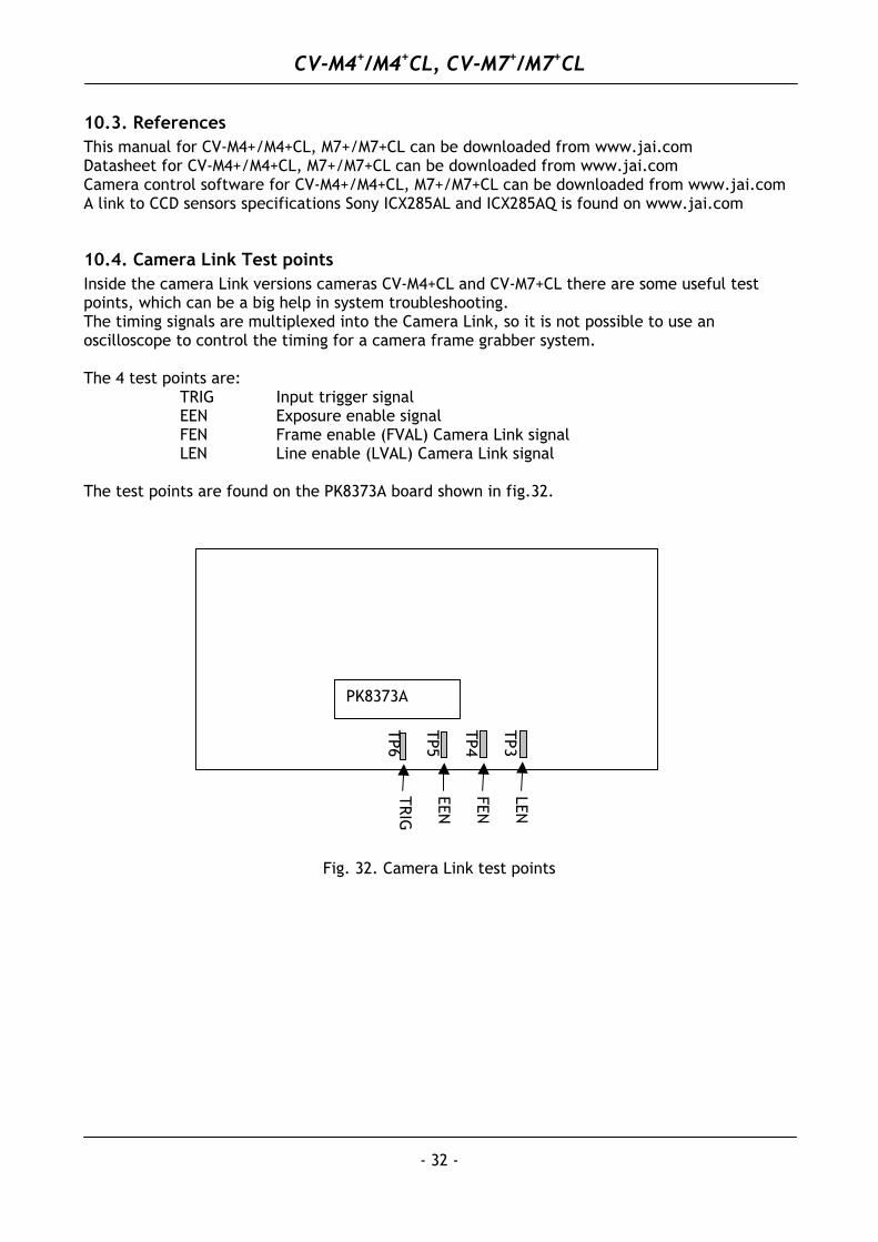
10.4. Camera Link Test points Inside the camera Link versions cameras CV-M4+CL and CV-M7+CL there are some useful test points, which can be a big help in system troubleshooting. The timing signals are multiplexed into the Camera Link, so it is not possible to use an oscilloscope to control the timing for a camera frame grabber system. The 4 test points are: TRIG Input trigger signal EEN Exposure enable signal FEN Frame enable (FVAL) Camera Link signal LEN Line enable (LVAL) Camera Link signal The test points are found on the PK8373A board shown in fig.32.
LEN
FEN
EEN
TRIG
TP3 TP4 TP5 TP6
PK8373A
Fig. 32. Camera Link test points
CV-M4+/M4+CL, CV-M7+/M7+CL
- 33 -
11. Users Record Camera type: CV-M4+ M4+CL M7+ M7+CL
Revision: (Revision C) Serial No. …………….. Software version. ……………..
For camera revision history, please contact your local JAI distributor. Users Mode Settings. Users Modifications.
DECLARATION OF CONFORMITY
AS DEFINED BY THE COUNCIL DIRECTIVE 89/336/EEC
EMC (ELECTROMAGNETIC COMPABILITY) WE HEREWITH DECLARE THAT THIS PRODUCT
COMPLIES WITH THE FOLOWING PROVISIONS APPLYING TO IT. EN-50081-1 EN-50082-1
Company and product names mentioned in this manual are trademarks or registered trademarks of their respective owners. JAI A-S cannot be held responsible for any technical or typographical errors and reserves the right to make changes to products and documentation without prior notification. JAI A-S, Denmark JAI Corporation, Japan JAI America.Inc., USA
Produktionsvej 1, 2600 Glostrup German Industry Center 800 West Cummings Park Copenhagen, Denmark 1-18-2 Hakusan, Midori-ku Woburn, MA 01801 Phone +45 4457 8888 Yokohama, Suite 1250 Fax +45 4491 8880 Kanagawa 226-0006, Japan Phone (Toll-Free) www.jai.com Phone +81 45 933 5400 +1 877 472-5909 Fax +81 45 931 6142 www.jai.com www.jai.com
CV-M4+ / M4+CL
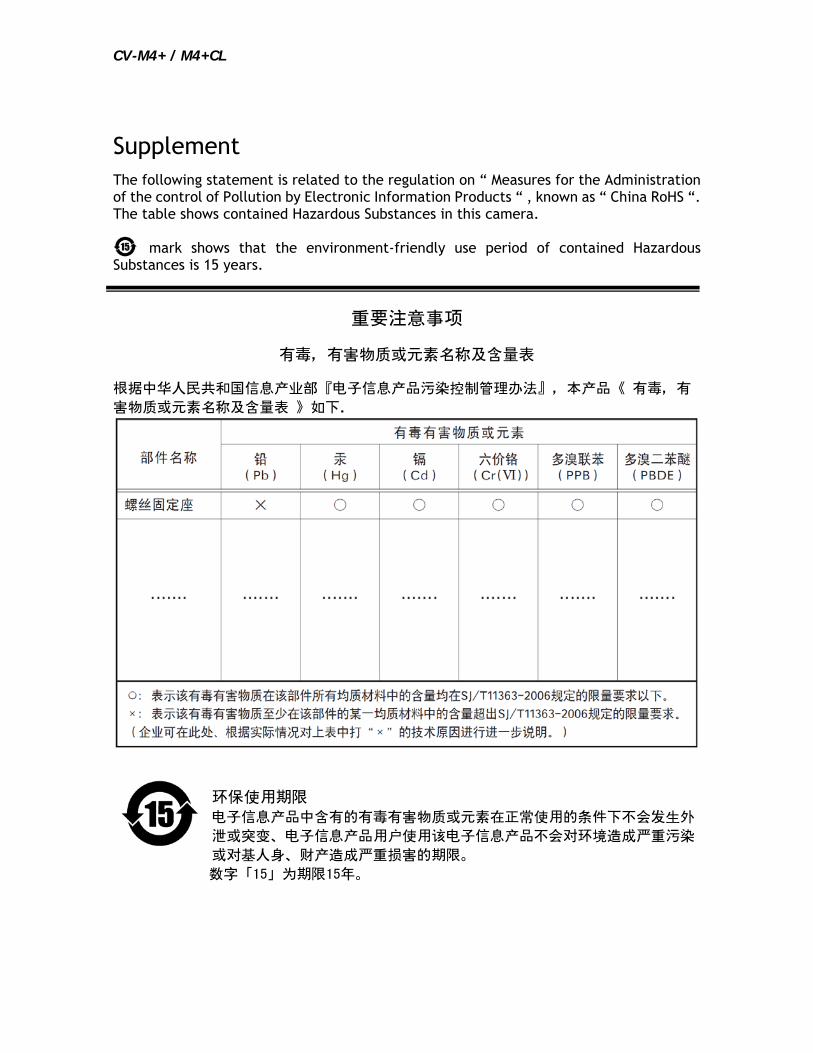
Supplement The following statement is related to the regulation on “ Measures for the Administration of the control of Pollution by Electronic Information Products “ , known as “ China RoHS “. The table shows contained Hazardous Substances in this camera.
mark shows that the environment-friendly use period of contained Hazardous Substances is 15 years.
嶷勣廣吭並
嗤蕎嗤墾麗嵎賜圷殆兆各式根楚燕
功象嶄鯖繁酎慌才忽佚連恢匍何〆窮徨佚連恢瞳麟半陣崙砿尖一隈〇云恢瞳ゞ 嗤蕎嗤
墾麗嵎賜圷殆兆各式根楚燕 〃泌和
桟隠聞喘豚 窮徨佚連恢瞳嶄根嗤議嗤蕎嗤墾麗嵎賜圷殆壓屎械聞喘議訳周和音氏窟伏翌
亶賜融延、窮徨佚連恢瞳喘薩聞喘乎窮徨佚連恢瞳音氏斤桟廠夛撹冢嶷麟半
賜斤児繁附、夏恢夛撹冢嶷鱒墾議豚。
方忖仝15々葎豚15定。
CV-M7+ / +CL / +CL-AOI
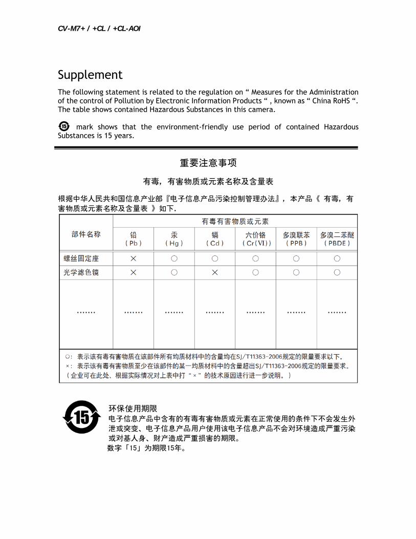
Supplement The following statement is related to the regulation on “ Measures for the Administration of the control of Pollution by Electronic Information Products “ , known as “ China RoHS “. The table shows contained Hazardous Substances in this camera.
mark shows that the environment-friendly use period of contained Hazardous Substances is 15 years.
嶷勣廣吭並
嗤蕎嗤墾麗嵎賜圷殆兆各式根楚燕
功象嶄鯖繁酎慌才忽佚連恢匍何〆窮徨佚連恢瞳麟半陣崙砿尖一隈〇云恢瞳ゞ 嗤蕎嗤
墾麗嵎賜圷殆兆各式根楚燕 〃泌和
桟隠聞喘豚 窮徨佚連恢瞳嶄根嗤議嗤蕎嗤墾麗嵎賜圷殆壓屎械聞喘議訳周和音氏窟伏翌
亶賜融延、窮徨佚連恢瞳喘薩聞喘乎窮徨佚連恢瞳音氏斤桟廠夛撹冢嶷麟半
賜斤児繁附、夏恢夛撹冢嶷鱒墾議豚。
方忖仝15々葎豚15定。