Digital Logic Design ENEE 244-010x - user.eng.umd.edudanadach/ENEE_244_Fall_15/lec_14_notes.pdf ·...
32
Digital Logic Design ENEE 244-010x Lecture 14
Transcript of Digital Logic Design ENEE 244-010x - user.eng.umd.edudanadach/ENEE_244_Fall_15/lec_14_notes.pdf ·...

Digital Logic Design ENEE 244-010x
Lecture 14

Announcements
• Homework 6 due today

Agenda
• Last time: – Binary Adders and Subtracters (5.1, 5.1.1) – Carry Lookahead Adders (5.1.2, 5.1.3)
• This time: – Decimal Adders (5.2) – Comparators (5.3) – Decoders (5.4) – Encoders (5.5) – Multiplexers (5.6)
• After introducing all the MSI components, we will go back and talk about how to use Decoders and Multiplexers for Logic Design.

Decimal Adders
8421 weighted coding scheme or BCD Code
Decimal Digit BCD
0 0000
1 0001
2 0010
3 0011
4 0100
5 0101
6 0110
7 0111
8 1000
9 1001
Forbidden codes: 1010, 1011, 1100, 1101, 1110,
1111

Decimal Adder
• Inputs: 𝐴3𝐴2𝐴1𝐴0, 𝐵3𝐵2𝐵1𝐵0, 𝐶𝑖𝑛 from previous decade.
• Output: 𝐶𝑜𝑢𝑡 (carry to next decade), 𝑍3𝑍2𝑍1𝑍0.
• Idea: Perform regular binary addition and then apply a corrective procedure.

Comparing Binary and BCD Sums Decimal Sum K 𝑷𝟑 𝑷𝟐 𝑷𝟏 𝑷𝟎 𝑪𝒐𝒖𝒕 𝒁𝟑 𝒁𝟐 𝒁𝟏 𝒁𝟎
0-9
10 0 1 0 1 0 1 0 0 0 0
11 0 1 0 1 1 1 0 0 0 1
12 0 1 1 0 0 1 0 0 1 0
13 0 1 1 0 1 1 0 0 1 1
14 0 1 1 1 0 1 0 1 0 0
15 0 1 1 1 1 1 0 1 0 1
16 1 0 0 0 0 1 0 1 1 0
17 1 0 0 0 1 1 0 1 1 1
18 1 0 0 1 0 1 1 0 0 0
19 1 0 0 1 1 1 1 0 0 1
---------Same-----------
𝐶𝑜𝑢𝑡 is set to 0

Decimal Adder
• No correction needed when the decimal sum is between 0-9.
• Must apply a correction when the sum is between 10-19.
• Case 1: – 16-19: K is set to 1. Add binary quantity 0110 to
𝑃3𝑃2𝑃1𝑃0. – 10-15: 𝐾𝑃3𝑃2𝑃1𝑃0 are set to 01010, 01011, . . ,
01111. Need to add 6. Use a K-map to obtain a Boolean expression to detect these six binary combinations.
A single-decade BCD Adder
Comparators
• Compare the magnitude of two binary numbers for the purpose of establishing whether one is greater than, equal to, or less than the other.
• A comparator makes use of a cascade connection of identical subnetworks similar to the case of the parallel adder.

Comparators
• Consider two n-bit binary numbers: 𝐴 = 𝐴𝑛−1 ⋯ 𝐴𝑖𝐴𝑖−1 ⋯ 𝐴1𝐴0 𝐵 = 𝐵𝑛−1 ⋯ 𝐵𝑖𝐵𝑖−1 ⋯ 𝐵1𝐵0
• Assume 𝐴𝑖 , 𝐵𝑖 are entering the subnetwork and that the binary numbers are analyzed from right to left.
• Subnetwork is called a 1-bit comparator.

Comparators
• 3 conditions describing the relative magnitudes of 𝐴𝑖−1 ⋯ 𝐴1𝐴0, 𝐵𝑖−1 ⋯ 𝐵1𝐵0
• 𝐺𝑖 = 1 denotes 𝐴𝑖−1 ⋯ 𝐴1𝐴0 > 𝐵𝑖−1 ⋯ 𝐵1𝐵0
• 𝐸𝑖 = 1 denotes 𝐴𝑖−1 ⋯ 𝐴1𝐴0 = 𝐵𝑖−1 ⋯ 𝐵1𝐵0
• 𝐿𝑖 = 1 denotes 𝐴𝑖−1 ⋯ 𝐴1𝐴0 < 𝐵𝑖−1 ⋯ 𝐵1𝐵0
• 1-bit comparator is a 5-input 3-output network

Comparators
• Rules:
– If 𝐴𝑖 = 0, 𝐵𝑖 = 1 then 𝐿𝑖 = 1
– If 𝐴𝑖 = 1, 𝐵𝑖 = 0 then 𝐺𝑖 = 1
– If 𝐴𝑖 = 𝐵𝑖 and 𝐿𝑖−1 = 1 then 𝐿𝑖 = 1
– If 𝐴𝑖 = 𝐵𝑖 and 𝐺𝑖−1 = 1 then 𝐺𝑖 = 1
– If 𝐴𝑖 = 𝐵𝑖 and 𝐸𝑖−1 = 1 then 𝐸𝑖 = 1
• Can use this to construct a truth table.

Comparators
• Minimal Sum Boolean Expressions:
𝐺𝑖+1 = 𝐴𝑖𝐵𝑖 + 𝐴𝑖𝐺𝑖 + 𝐵𝑖𝐺𝑖
𝐸𝑖+1 = 𝐴𝑖𝐵𝑖𝐸𝑖 + 𝐴𝑖𝐵𝑖𝐸𝑖
𝐿𝑖+1 = 𝐴𝑖𝐵𝑖 + 𝐵𝑖𝐿𝑖 + 𝐴𝑖𝐿𝑖

Comparators

Comparators

Decoder
• Digital information represented in some binary form must be converted into some alternate binary form.
• 𝑛 to 2𝑛-line decoder.
• Only one of the 2𝑛 output lines responds, with a logic-1, to a given input combination of values on its 𝑛-input lines.

Realization
Logic Diagram
Truth Table
Symbol

Decoder
• Input combinations can be regarded as binary numbers with the consequences that the j-th output line is at logic-1 for j = 0, 1, . . , 7 only when input combination j is applied.
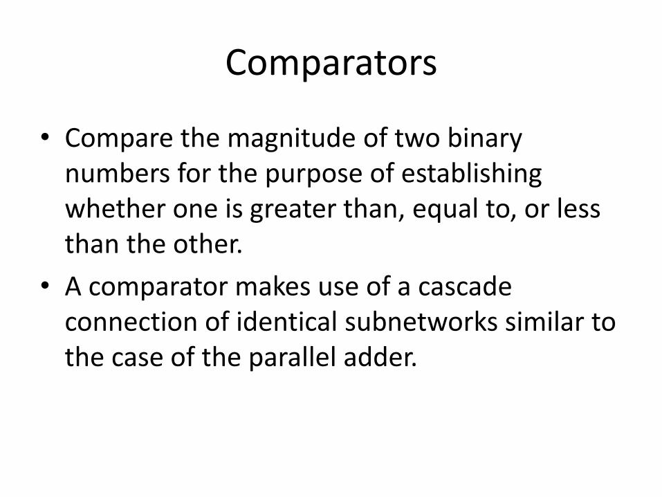
Decoders with an Enable Input
Logic Diagram
Truth Table
Symbol

Decoders with enable inputs • When disabled, all outputs of the decoder can either
be at logic-0 or logic-1. • Enable input provides the decoder with additional
flexibility. Idea: data is applied to the enable input. • Process is known as demultiplexing.
• Enable inputs are useful when constructing larger decoders from smaller decoders.
Data
𝑥0𝑥1𝐸
If 𝑥0 = 0, 𝑥1 = 0 then data appears on line 𝑧0.

Constructing Larger Decoders

Encoders • Encoders provide for the conversion of binary information from one
form to another. • Encoders are essentially the inverse of decoders. • 2𝑛-to-𝑛-line encoder in which an assertive logic value on one of its
2𝑛-input lines causes the corresponding binary code to appear at the output lines.
𝒙𝟎 𝒙𝟏 𝒙𝟐 𝒙𝟑 𝒙𝟒 𝒙𝟓 𝒙𝟔 𝒙𝟕 𝒛𝟎 𝒛𝟏 𝒛𝟐
0 0 0 0 0 0 0 1 1 1 1
0 0 0 0 0 0 1 0 1 1 0
0 0 0 0 0 1 0 0 1 0 1
0 0 0 0 1 0 0 0 1 0 0
0 0 0 1 0 0 0 0 0 1 1
0 0 1 0 0 0 0 0 0 1 0
0 1 0 0 0 0 0 0 0 0 1
1 0 0 0 0 0 0 0 0 0 0

Encoders • Equations for 8-to-3-line encoder:
𝑧0 = 𝑥1 + 𝑥3 + 𝑥5 + 𝑥7 𝑧1 = 𝑥2 + 𝑥3 + 𝑥6 + 𝑥7 𝑧2 = 𝑥4 + 𝑥5 + 𝑥6 + 𝑥7
• In general, the Boolean expression for the output 𝑧𝑖 is the sum of each input 𝑥𝑗 in which the binary representation of 𝑗 has a 1 in the 2𝑖-bit
position.

Priority Encoder
• The assumption that at most a single input to the encoder is asserted at any time is significant in its operation. – Example: Both 𝑥3 (11) and 𝑥5 (101) are asserted.
What is the output?
– 111 𝑥7
• Priority Encoder: – A priority scheme is assigned to the input lines so that
whenever more than one input line is asserted at any time, the output is determined by the input line having the highest priority.

Priority Encoder
The output is determined by the asserted input having the highest index. 𝑥𝑖 has higher priority than 𝑥𝑗 if 𝑖 > 𝑗.
“Valid” indicates that at least one input line is asserted. This distinguishes the situation that no input line is asserted from when the 𝑥0 input line is asserted, since in both cases 𝑧2𝑧1𝑧0 = 000.

Multiplexer
• Also called data selectors.
• Basic function: select one of its 2𝑛 data input lines and place the corresponding information onto a single output line.
• 𝑛 input bits needed to specify which input line is to be selected.
– Place binary code for a desired data input line onto its 𝑛 select input lines.

Realization of 4-to-1 line multiplexer
Logic Diagram
Truth Table
Symbol

Realization of 4-to-1 line multiplexer
• Alternate description:
• Algebraic description of multiplexer:
𝑓 = 𝐼0𝑆1𝑆0 + 𝐼1𝑆1𝑆0 + 𝐼2𝑆1𝑆0 + 𝐼3𝑆1𝑆2 𝐸

Building a Large Multiplexer
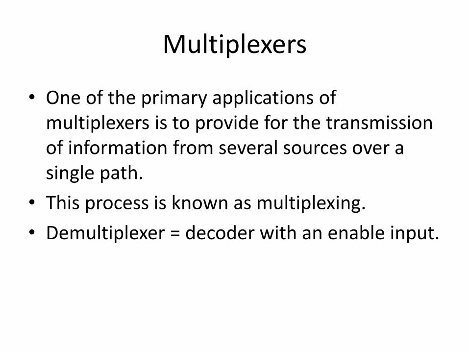
Multiplexers
• One of the primary applications of multiplexers is to provide for the transmission of information from several sources over a single path.
• This process is known as multiplexing.
• Demultiplexer = decoder with an enable input.

Multiplexer/Demultiplexer for information transmission


![Journal of Experimental Zoology Part a Ecological Genetics and Physiology Volume 275 Issue 2-3 1996 [Doi 10.1002%2F%28sici%291097-010x%2819960601%2F15%29275%3A2%2F3%3C217%3A%3Aaid-Jez13%3E3.0.Co%3B2-g]](https://static.fdocuments.net/doc/165x107/577cdf1c1a28ab9e78b08029/journal-of-experimental-zoology-part-a-ecological-genetics-and-physiology-volume.jpg)