Digital High-Speed Marking and Coding
14
Digital High-Speed Marking and Coding: Improving Quality and Throughput A GUIDE Product and packaging manufacturing are continuously evolving, but one constant remains: the need to mark items accurately and permanently. The on-going advancement in these industries drives new demands in throughput. These require that marks maintain quality to properly represent brand image or enable proper vision inspection. ©2020 Novanta Corporation. All rights reserved. This paper examines a digital approach to marking using a laser and scan head, including selection of system components and optimizing settings to achieve processing goals for throughput and quality. High Speed Marking Several components influence the final outcome of any laser application, including: the target material, the desired application or mark itself, the laser, and the beam delivery (in this case a scan head). The scan head is easily the most complex portion of this equation, requiring a balance of product specifications, optics, controller/software performance, and finally optimizing settings. To help illustrate each of these decisions, we will consider an example: high speed marking of ink-coated paperboard, a common application in the packaging industry.
Transcript of Digital High-Speed Marking and Coding

Digital High-Speed Marking and Coding:Improving Quality and Throughput
A GUIDE
Product and packaging manufacturing are continuously evolving, but one constant remains: the need to mark items accurately and permanently. The on-going advancement in these industries drives new demands in throughput. These require that marks maintain quality to properly represent brand image or enable proper vision inspection.
©2020 Novanta Corporation. All rights reserved.
This paper examines a digital approach to marking using a laser and scan head, including selection of system components and optimizing settings to achieve processing goals for throughput and quality.
High Speed Marking
Several components influence the final outcome of any laser application, including: the target material, the desired application or mark itself, the laser, and the beam delivery (in this case a scan head). The scan head is easily the most complex portion of this equation, requiring a balance of product specifications, optics, controller/software performance, and finally optimizing settings. To help illustrate each of these decisions, we will consider an example: high speed marking of ink-coated paperboard, a common application in the packaging industry.

Digital High-Speed Marking and Coding: Improving Quality and Throughput
©2020 Novanta Corporation. All rights reserved.
Target Material
Every material has a characteristic absorption spectrum, meaning that it will absorb certain wavelengths of light more readily than others. By matching the laser wavelength to high absorption in the material, we can achieve higher throughput.
Certain materials may also be more sensitive to variations in power density, making them more susceptible to inconsistent marking. Therefore, it is also important to have a stable laser and reliable beam delivery system to ensure consistent results.
We will use an ink-coated paperboard as an example, commonly known as “marking paper in the laser industry. This application is similar to one commonly found in the packaging industry, where manufacturers must ablate through an ink layer to reveal a contrasting colored layer beneath.
Absorption spectrum for marking paper
©2020 Novanta Corporation. All rights reserved.
Digital High-Speed Marking and Coding: Improving Quality and Throughput
Application
The application design will have a large impact on achievable throughput. For example, larger filled logos will necessarily require more time than a few characters in a simple vector stroke font. Other considerations include:
3 The design itself: could a smaller design or simpler font suffice? Is hatching an appropriate substitution for a filled graphic? Will the mark need to be read from a distance?
3 Quality requirements: will characters or barcodes need to be machine readable? Are there regulatory or brand requirements?
3 Throughput requirements: is there a set line or conveyor speed that needs to be met?
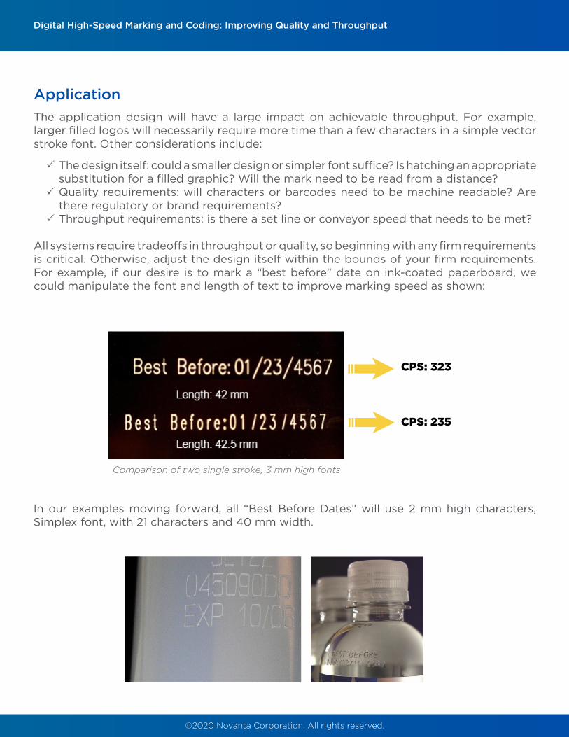
All systems require tradeoffs in throughput or quality, so beginning with any firm requirements is critical. Otherwise, adjust the design itself within the bounds of your firm requirements. For example, if our desire is to mark a “best before” date on ink-coated paperboard, we could manipulate the font and length of text to improve marking speed as shown:
In our examples moving forward, all “Best Before Dates” will use 2 mm high characters, Simplex font, with 21 characters and 40 mm width.
CPS: 323
CPS: 235
Comparison of two single stroke, 3 mm high fonts
©2020 Novanta Corporation. All rights reserved.
Digital High-Speed Marking and Coding: Improving Quality and Throughput
Laser
As previously mentioned, materials each have a unique absorption spectrum. By optimizing the laser wavelength to maximize absorption, we optimize throughput. Therefore, it is critical to choose a laser producing light that is well absorbed by your material. Generally, CO
2 laser
wavelengths are absorbed well by carbon-based materials like papers and plastics, while Fiber and UV laser wavelengths are better absorbed by metals and glass.
Laser wavelength will also impact focused spot size and Rayleigh length. A smaller focused spot size allows greater detail in a mark and greater power density for faster processing. The Rayleigh length determines the depth of focus, which controls the tolerance of the system to changes in part height. For example, a larger depth of focus may allow parts with slight variations in height or a surface curvature to still mark consistently. Generally, longer wavelengths lead to larger focused spot sizes and longer Rayleigh lengths.
Laser power—specifically average power—and throughput speed are directly related. However, there are limits imposed by the scan head and the material itself. Maximum scan head speed will be restricted by the physical limitation of mirror movement and certain materials may discolor, melt, or crack if exposed to excess energy. Balancing these factors typically results in 30-100 W of average laser power for high speed marking applications.
Finally, laser power density stability should be considered. This includes both the power stability and the consistency of the laser beam it produces. Changes in power density can appear on very sensitive materials as marks that fade in and out.
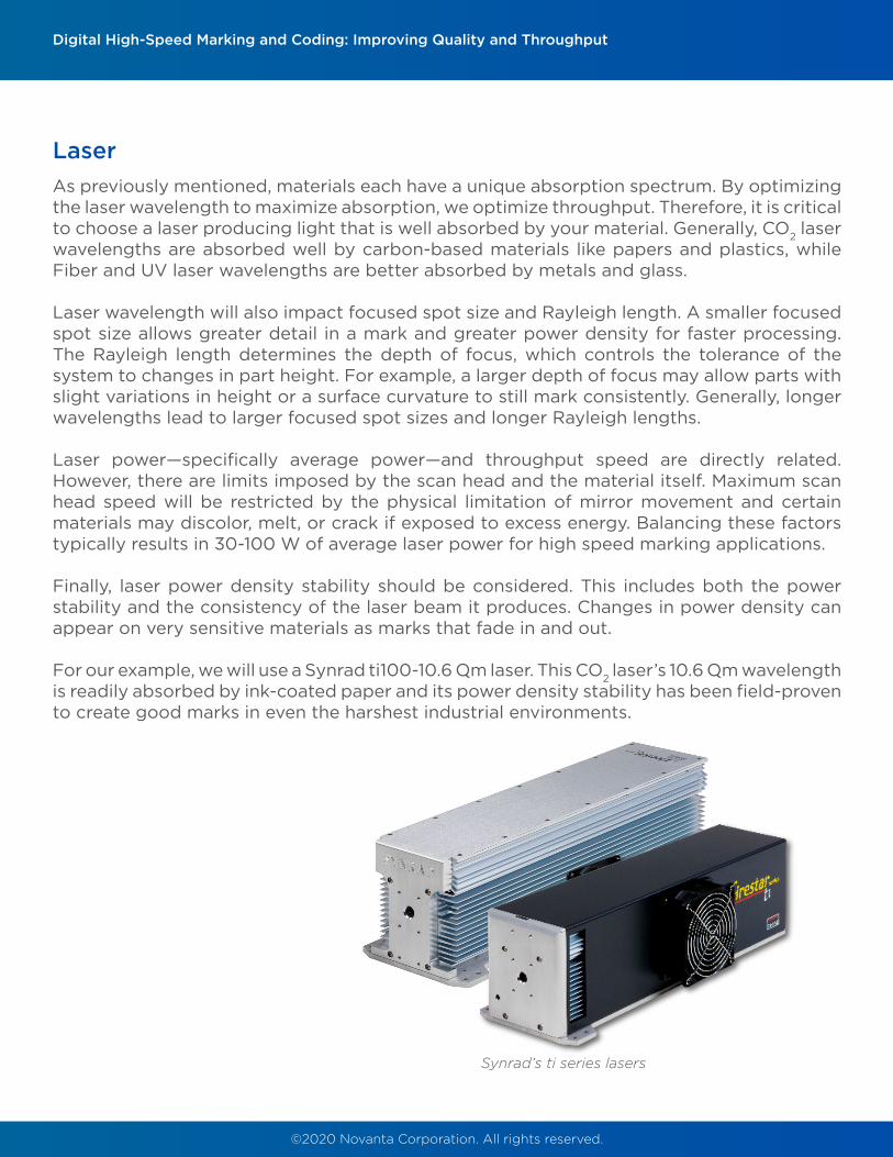
For our example, we will use a Synrad ti100-10.6 μm laser. This CO2 laser’s 10.6 μm wavelength
is readily absorbed by ink-coated paper and its power density stability has been field-proven to create good marks in even the harshest industrial environments.
Synrad’s ti series lasers

©2020 Novanta Corporation. All rights reserved.
Scan Head
Since the scan head is responsible for beam delivery, choosing one with appropriate specifications as a starting point will allow later fine-tune adjustment to achieve the desired application results.
The choice of scan head mirror size will have a direct impact on application quality and throughput. Smaller mirrors will allow greater mark acceleration, due to their lower mass. However, they can limit the input laser beam diameter and thus affect focal diameter and Rayleigh length (more on this in a moment). Selecting mirror size will therefore be a balance of providing enough acceleration for the application, while maintaining acceptable values for focal diameter and Rayleigh length. Typically, high speed coding applications use 7 mm or 10 mm mirror apertures and industrial marking applications will use a 10 mm, 14 mm, or even larger mirror aperture. 10 mm mirror apertures represent the best of both worlds, allowing the high speeds necessary for most coding applications, while offering the flexibility necessary to support industrial marking.
When reviewing scan head performance, there are a few categories to bear in mind: reliability, speed, precision, and consistency.
3 Uptime is paramount for high speed marking and coding. Consider scan heads from brands with excellent reputations, offering long warranties to help gauge reliability. IP-ratings will ensure functionality even in harsh environments.
3 To evaluate speed, consider Positioning Speed and Step Response Time. Positioning Speed reflects the system’s maximum jump speed, which is useful for allowing higher conveyor speeds for on-the-fly marking and shortening individual application times. Step Response Time indicates how quickly a scan head can execute motion (specifically: the time required for galvos to settle within 1% of final position given a certain sized step command). This is divided into two categories: small step response (0.1 mechanical degree) and large step response (20 degrees). The short step response is inversely proportional to the large step response, meaning it is impossible to have both a quick short step response (SSR) and large step response (LSR). The short step response is the critical parameter for high speed marking and coding applications since it best represents the small, fast motions used to form characters and small objects like logos or barcodes.
3 To gauge precision and consistency, consider drift and repeatability values. Low values for Long Term Offset Drift evaluated over a longer time period indicate a system that is more accurate and will remain that way. Temperature Offset Drift and Temperature Scale Drift values indicate a system’s susceptibility to temperature variations; again, low values indicate a more stable system. Repeatability, as you may suspect, is a measure of how closely a galvo can target the same commanded position time after time. Smaller values indicate better positional accuracy. Combined, these drift and repeatability values indicate how precise a scan head is over time and in varying conditions. Small values are useful for maintaining tight marking tolerances in applications.
Digital High-Speed Marking and Coding: Improving Quality and Throughput
©2020 Novanta Corporation. All rights reserved.
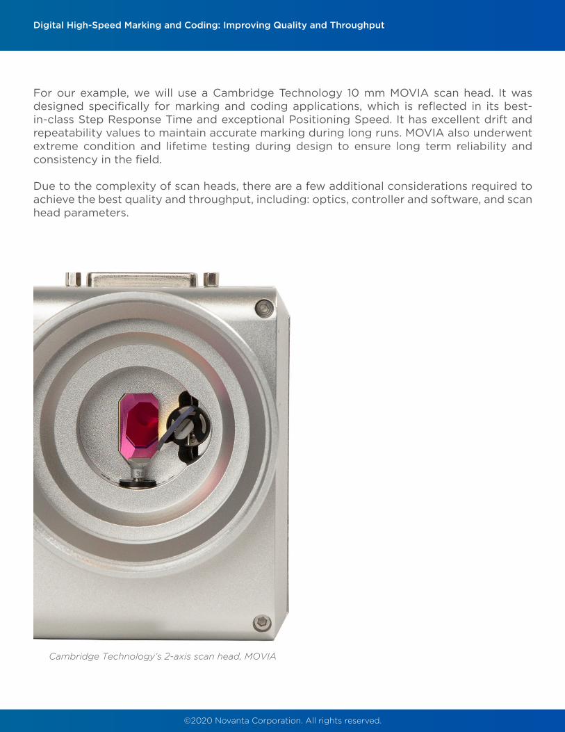
For our example, we will use a Cambridge Technology 10 mm MOVIA scan head. It was designed specifically for marking and coding applications, which is reflected in its best-in-class Step Response Time and exceptional Positioning Speed. It has excellent drift and repeatability values to maintain accurate marking during long runs. MOVIA also underwent extreme condition and lifetime testing during design to ensure long term reliability and consistency in the field.
Due to the complexity of scan heads, there are a few additional considerations required to achieve the best quality and throughput, including: optics, controller and software, and scan head parameters.
Digital High-Speed Marking and Coding: Improving Quality and Throughput
Cambridge Technology’s 2-axis scan head, MOVIA

©2020 Novanta Corporation. All rights reserved.
Focusing Optics
Focusing optics should be chosen to provide the desired focal spot size, Rayleigh Length, and field size to support the application.
3 A laser focused into a smaller focal diameter will have higher power density, allowing the same laser to process more quickly. Smaller spot sizes also provide greater detail for fine marks or images.
3 Rayleigh length determines depth of focus (this is the range above and below the focal plane in which the converging/diverging laser beam has enough power density to achieve good laser processing results). Larger depth of focus creates more flexibility in the system to achieve good mark results despite small irregularities in part height or surface flatness. This can be useful to overcome small part-to-part variance in a manufacturing environment.
3 Field sizes should be chosen to encompass the desired mark area. Larger field sizes can also be useful for allowing higher conveyor speeds, since the scan head has more time to mark each part before it moves beyond the field of view.
Digital High-Speed Marking and Coding: Improving Quality and Throughput
We have chosen a 10 mm MOVIA scan head with a 150 mm working distance for our high-speed marking application. Combined with the 10.6 μm ti100 laser, this produces a focus diameter of 300 μm, a Rayleigh length of 7 mm and a field size of 100 x 100 mm2. This will provide sufficient power density to mark the ink-coated paperboard at the speeds provided by the 10 mm mirrors.
©2020 Novanta Corporation. All rights reserved.
Controller and Software
The command structure that governs the scan head/laser system will highly influence the application results. Controlling the motion and especially the timing of marks is critical to achieving the best quality and throughput for the system. Critical parameters include: mark and jump speed, scan head and laser delay settings, and two optional settings for improving throughput and quality called Variable Poly Delay (VPD) and Velocity Compensation, respectively.
Though the combination of MOVIA and the ti100 laser could function with any controller using XY2-100 protocol, we find that pairing it with ScanMaster Controller and Designer produces consistently higher quality and better throughput. Cambridge Technology’s Application Engineers also have tools and guidelines available for this pairing to help customers quickly set up jobs and begin manufacturing runs.
Mark and Jump Speeds
As the names imply, Mark Speed refers to the speed of galvo motion while the laser is firing and Jump Speed refers to the speed while the galvos “jump” to a new location with the laser off. Jump Speed should be set high enough to maximize throughput without causing instability in the galvo motion as the mirrors decelerate to their next mark position. Incorrect values for these two speeds will cause the target material to burn, melt, or discolor if the speed is too slow or give a faded or shallow appearance if the speed is too high. The speeds chosen for our ti100 and MOVIA setup were: Mark Speed: 15,000 mm/s and Jump Speed: 30,000 mm/s. These were combined with laser settings (60% Duty Cycle and 80 kHz Frequency) to achieve consistent marking with no discoloration.
Scan Head Delay Settings
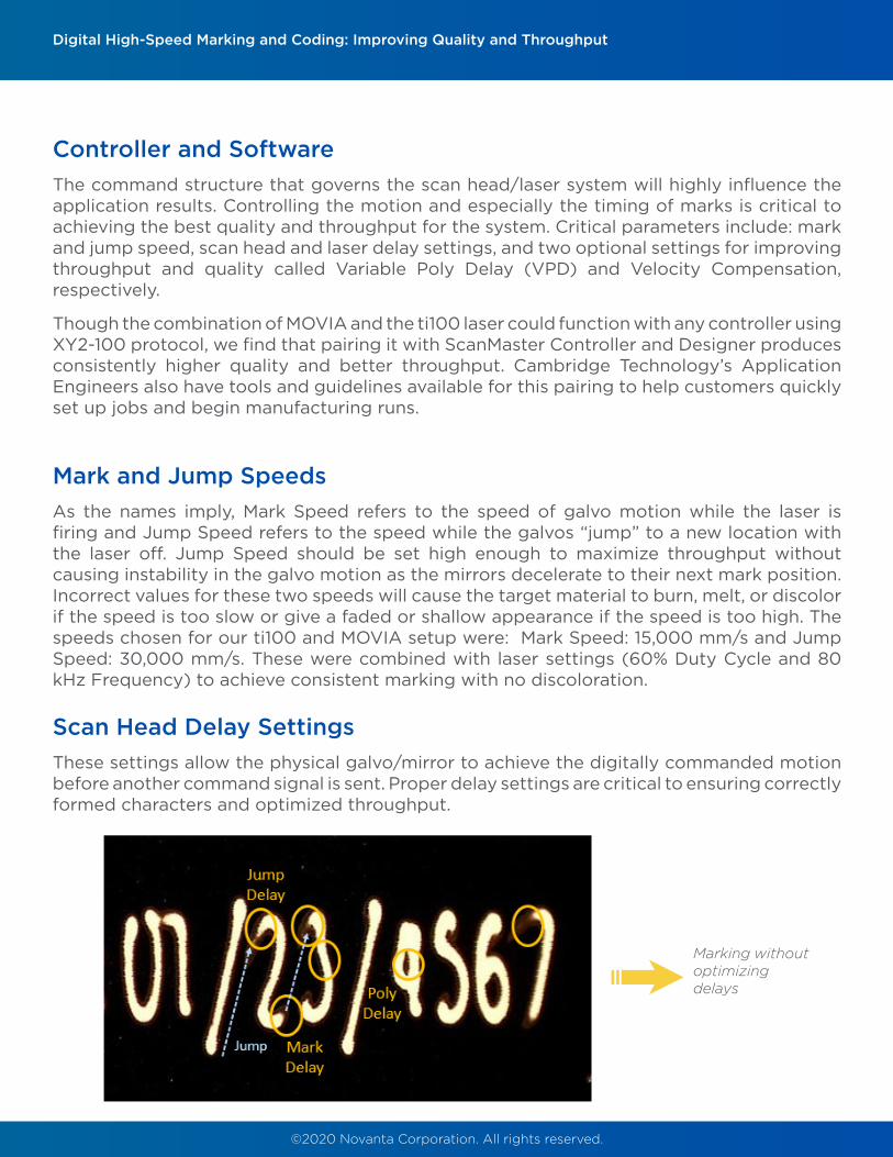
These settings allow the physical galvo/mirror to achieve the digitally commanded motion before another command signal is sent. Proper delay settings are critical to ensuring correctly formed characters and optimized throughput.
Digital High-Speed Marking and Coding: Improving Quality and Throughput
Marking without optimizing delays
©2020 Novanta Corporation. All rights reserved.
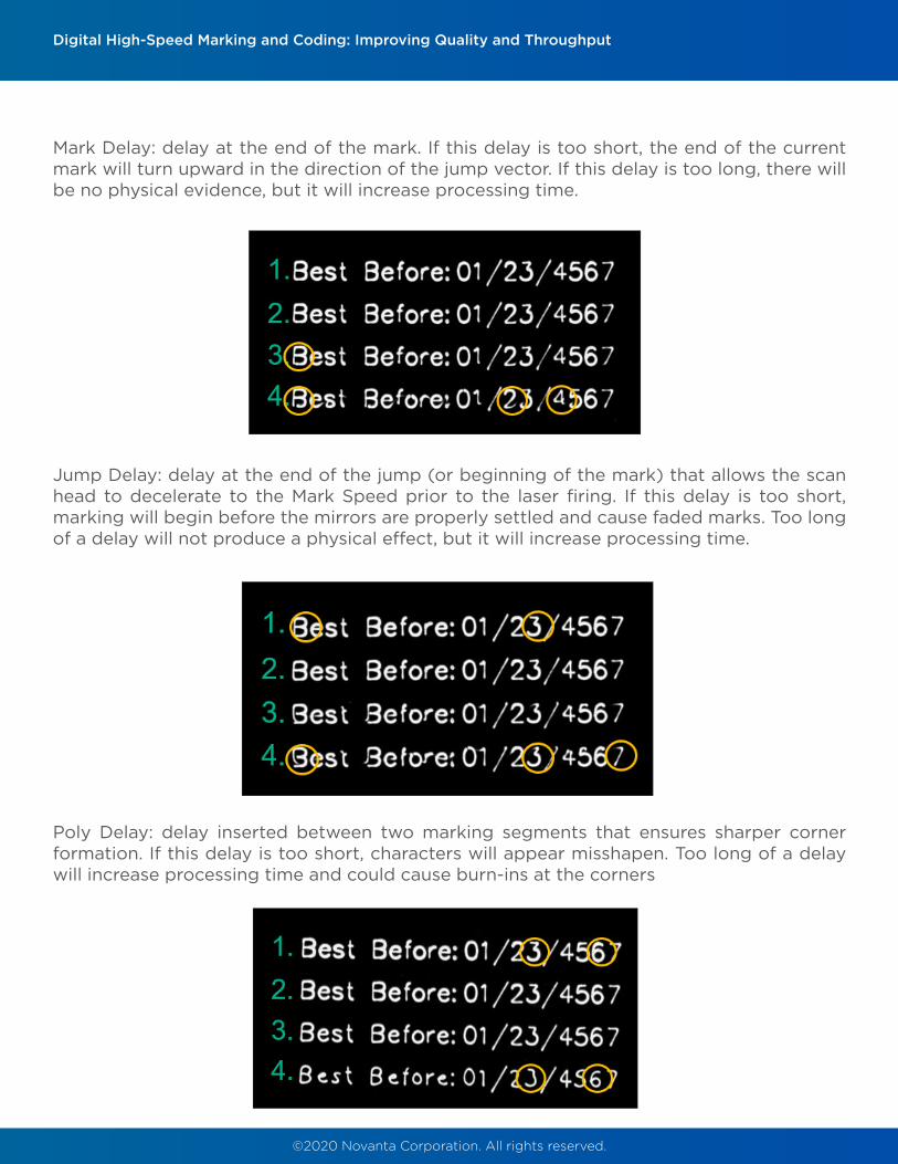
Mark Delay: delay at the end of the mark. If this delay is too short, the end of the current mark will turn upward in the direction of the jump vector. If this delay is too long, there will be no physical evidence, but it will increase processing time.
Digital High-Speed Marking and Coding: Improving Quality and Throughput
Jump Delay: delay at the end of the jump (or beginning of the mark) that allows the scan head to decelerate to the Mark Speed prior to the laser firing. If this delay is too short, marking will begin before the mirrors are properly settled and cause faded marks. Too long of a delay will not produce a physical effect, but it will increase processing time.
Poly Delay: delay inserted between two marking segments that ensures sharper corner formation. If this delay is too short, characters will appear misshapen. Too long of a delay will increase processing time and could cause burn-ins at the corners

©2020 Novanta Corporation. All rights reserved.
Delay Overview
Throughput and quality exist on opposite ends of the application spectrum, and only the end user can determine the proper tradeoff in acceptable quality verses higher throughput. Delays should therefore be used to optimize certain features according to your needs. Two examples are shown here, the first marked with the ti100 and MOVIA system from our example across various delay settings
Digital High-Speed Marking and Coding: Improving Quality and Throughput
The second is a MOVIA and fiber laser system marking coated glass to show achievable character formation at various speeds

©2020 Novanta Corporation. All rights reserved.
Optional Settings: Variable Poly Delay
This delay is a feature of our software, ScanMaster, designed to improve throughput and may sacrifice quality. Examples have exhibited up to 65% throughput increase. Variable Poly Delay (VPD) adjusts the standard Poly Delay based on the angle between vectors during marking, allowing greater delay time for more demanding deceleration/acceleration commands.
Digital High-Speed Marking and Coding: Improving Quality and Throughput
An example of this is shown with the MOVIA and ti100 setup below:
Each mark uses the same parameters: Marking Speed: 15 m/s; Jump Speed: 30 m/s; Mark Delay: 60 μs; Jump Delay: 100 μs, and Poly Delay: 60 μs. Note that with VPD enabled, corners are less sharp, but throughput was increased by 12%.
©2020 Novanta Corporation. All rights reserved.
Digital High-Speed Marking and Coding: Improving Quality and Throughput
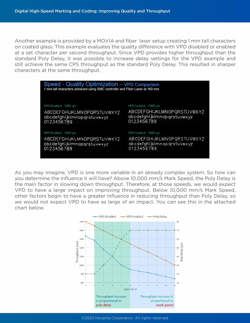
Another example is provided by a MOVIA and fiber laser setup creating 1 mm tall characters on coated glass. This example evaluates the quality difference with VPD disabled or enabled at a set character per second throughput. Since VPD provides higher throughput than the standard Poly Delay, it was possible to increase delay settings for the VPD example and still achieve the same CPS throughput as the standard Poly Delay. This resulted in sharper characters at the same throughput.
As you may imagine, VPD is one more variable in an already complex system. So how can you determine the influence it will have? Above 10,000 mm/s Mark Speed, the Poly Delay is the main factor in slowing down throughput. Therefore, at those speeds, we would expect VPD to have a large impact on improving throughput. Below 10,000 mm/s Mark Speed, other factors begin to have a greater influence in reducing throughput than Poly Delay, so we would not expect VPD to have as large of an impact. You can see this in the attached chart below.

©2020 Novanta Corporation. All rights reserved.
Digital High-Speed Marking and Coding: Improving Quality and Throughput
On the left, mark speeds exceed 10,000 mm/s and we see that the throughput increase due to VPD is proportional to the increasing poly delay— this example also displays a significant throughput increase of up to 65%. On the right, mark speeds are below 10,000 mm/s and the throughput increase due to VPD is now proportional to Mark Speed, which has a reduced effect as speeds decrease. That is the reason why this example using the MOVIA and ti100 system shows throughput increases not proportional to the Poly Delay. Both the parameters (speed and delays) as well as the font size (2 mm) also played a factor in the final throughput.
Ultimately, the best way to determine whether to use VPD or not is to run a series of marks given your particular application requirements on your material.
In this example, character formation begins to suffer as character per second throughput is increased. However, all characters are human readable, and that may be sufficient for a given application, it will remain for the end user to decide.

©2020 Novanta Corporation. All rights reserved.
Conclusion
Quality and throughput exist on a spectrum, and ultimately the end user must choose which tradeoffs are appropriate for their application. Material and application design will have a large impact on the final outcome, but smart choices in equipment (including laser, scan head, optics, controller, and software) will ensure the best quality and throughput achievable. By carefully manipulating system speed, delays, and optional settings, quality features can be optimized while maintaining acceptable throughput. Ultimately each application will be a balance of quality, throughput, and system capabilities.
Novanta Advantage
Novanta’s global system of Application Laboratories deliver solutions for the most challenging processing demands. Customers have access to regional locations with a wide variety of equipment to provide fast, in-depth responses to their application challenges. Our engineers are well-versed across Novanta’s wide range of products and will provide a complete solution to any manufacturing obstacles you face. We are happy to perform application testing on your materials to your specifications to ensure your needs are met.Contact us below to learn more.
Digital High-Speed Marking and Coding: Improving Quality and Throughput
Contact Us Here
Optional Settings: Velocity Compensation
This setting improves energy distribution to yield better mark consistency (higher quality). It does so by adjusting laser parameters—including Duty Cycle, Frequency, and Power—based on the speed of the galvo motion during marking. This creates more consistent energy deposition to the material, creating marks with uniform appearance for a higher quality result