Digital Fiber Sensors E3X-DA-S - Farnell element14 · E3X-DA-S Digital Fiber Sensors 1 Digital...
32
E3X-DA-S Digital Fiber Sensors 1 Digital Fiber Sensors E3X-DA-S The next-generation platform for a wide range of sensing • The industry's first Power Tuning function in a digital amplifier. • Large, easy-to-read displays that are clear even from a distance. Seven convenient display formats. • Stable long-term performance achieved with OMRON's APC function. • A wide array of advanced functions for even more ap- plications. • The same ease-of-use as the E3X-DA-N Amplifiers. • Environmentally friendly design. • Improved Mobile Console. Ordering Information ■ Amplifier Units Amplifier Units with Cables Amplifier Units with Connectors ■ Amplifier Unit Connectors (Order Separately) Item Appearance Functions Model NPN output PNP output Standard models --- E3X-DA11-S E3X-DA41-S Mark-detecting models Green LED --- E3X-DAG11-S E3X-DAG41-S Blue LED --- E3X-DAB11-S E3X-DAB41-S Advanced models Twin-output models Area output, self-diagnosis, differential operation E3X-DA11TW-S E3X-DA41TW-S External-input models Remote setting, counter, dif- ferential operation E3X-DA11RM-S E3X-DA41RM-S Item Appearance Functions Model NPN output PNP output Standard models --- E3X-DA6-S E3X-DA8-S Mark-detecting models Green LED --- E3X-DAG6-S E3X-DAG8-S Blue LED --- E3X-DAB6-S E3X-DAB8-S Advanced models Twin-output models Area output, self-diagnosis, differential operation E3X-DA6TW-S E3X-DA8TW-S External-input models Remote setting, counter, dif- ferential operation E3X-DA6RM-S E3X-DA8RM-S Item Appearance Cable length No. of conductors Model Master Connector 2 m 3 E3X-CN11 4 E3X-CN21 Slave Connector 1 E3X-CN12 2 E3X-CN22
Transcript of Digital Fiber Sensors E3X-DA-S - Farnell element14 · E3X-DA-S Digital Fiber Sensors 1 Digital...

E3X-DA-S Digital Fiber Sensors 1
Digital Fiber Sensors
E3X-DA-SThe next-generation platform for a wide range of sensing• The industry's first Power Tuning function in a digital
amplifier.• Large, easy-to-read displays that are clear even from
a distance. Seven convenient display formats.• Stable long-term performance achieved with
OMRON's APC function.• A wide array of advanced functions for even more ap-
plications.• The same ease-of-use as the E3X-DA-N Amplifiers.• Environmentally friendly design.• Improved Mobile Console.
Ordering Information
■ Amplifier Units
Amplifier Units with Cables
Amplifier Units with Connectors
■ Amplifier Unit Connectors (Order Separately)
Item Appearance Functions Model
NPN output PNP output
Standard models --- E3X-DA11-S E3X-DA41-S
Mark-detecting models
Green LED --- E3X-DAG11-S E3X-DAG41-S
Blue LED --- E3X-DAB11-S E3X-DAB41-S
Advanced models
Twin-output models
Area output, self-diagnosis, differential operation
E3X-DA11TW-S E3X-DA41TW-S
External-input models
Remote setting, counter, dif-ferential operation
E3X-DA11RM-S E3X-DA41RM-S
Item Appearance Functions Model
NPN output PNP output
Standard models --- E3X-DA6-S E3X-DA8-S
Mark-detecting models
Green LED --- E3X-DAG6-S E3X-DAG8-S
Blue LED --- E3X-DAB6-S E3X-DAB8-S
Advanced models
Twin-output models
Area output, self-diagnosis, differential operation
E3X-DA6TW-S E3X-DA8TW-S
External-input models
Remote setting, counter, dif-ferential operation
E3X-DA6RM-S E3X-DA8RM-S
Item Appearance Cable length No. of conductors Model
Master Connector 2 m 3 E3X-CN11
4 E3X-CN21
Slave Connector 1 E3X-CN12
2 E3X-CN22

2 E3X-DA-S Digital Fiber Sensors
Combining Amplifier Units and ConnectorsAmplifier Units and Connectors are sold separately. Refer to the following tables when placing an order.
When Using 5 Amplifier Units
■ Mobile Console (Order Separately)
Note:Use the E3X-MC11-S Mobile Console for the E3X-DA-S-series Amplifier Units. Other Mobile Consoles cannot be used.
■ Accessories (Order Separately)
Mounting Bracket
End Plate
Amplifier Unit Applicable Connector (Order Separately)
Model NPN output PNP output Master Connector Slave Connector
Standard models E3X-DA6-S E3X-DA8-S E3X-CN11 (3-wire) E3X-CN12 (1-wire)
Mark-detecting models
E3X-DAG6-S E3X-DAG8-S +E3X-DAB6-S E3X-DAB8-S
Advanced models E3X-DA6TW-S E3X-DA8TW-S E3X-CN21 (4-wire) E3X-CN22 (2-wire)
E3X-DA6RM-S E3X-DA8RM-S
Amplifier Units (5 Units) + 1 Master Connector + 4 Slave Connectors
Appearance Model Remarks
E3X-MC11-S (model number of set)
Mobile Console with Head, Ca-ble, and AC adapter provided as accessories
E3X-MC11-C1-S Mobile Console
E3X-MC11-H1 Head
E39-Z12-1 Cable (1.5 m)
Appearance Model Quantity
E39-L143 1
Appearance Model Quantity
PFP-M 1

E3X-DA-S Digital Fiber Sensors 3
Specifications
■ Ratings/Characteristics
Amplifier Units
Amplifier Units with CablesType Standard mod-
elsMark-detecting models Advanced, twin-
output modelsAdvanced, external-
input models
Model NPN output E3X-DA11-S E3X-DAG11-S E3X-DAB11-S E3X-DA11TW-S E3X-DA11RM-S
Item PNP output E3X-DA41-S E3X-DAG41-S E3X-DAB41-S E3X-DA41TW-S E3X-DA41RM-S
Light source (wavelength) Red LED (650 nm)
Green LED (525 nm)
Blue LED (470 nm)
Red LED (650 nm)
Supply voltage 12 to 24 VDC �10%, ripple (p-p) 10% max.
Power consumption 960 mW max. (current consumption: 40 mA max. at power supply voltage of 24 VDC)
1,080 mW max. (current consumption: 45 mA max. at power supply voltage of 24 VDC)
Control output Load power supply voltage: 26.4 VDC; NPN/PNP open collector; load current: 50 mA max.; residual voltage: 1 V max.
Circuit protection Reverse polarity for power supply connection, output short-circuit
Response time
Super-high-speed mode
NPN 48 �s for operation and 50 �s for reset
80 �s for operation and reset respective-ly
48 �s for operation and 50 �s for reset*1
PNP 53 �s for operation and 55 �s for reset
53 �s for operation and 55 �s for reset*1
Standard mode 1 ms for operation and reset respectively
High-resolution mode 4 ms for operation and reset respectively
Sensitivity setting Teaching or manual method
Functions Power tuning Light emission power and reception gain, digital control method
Differential detection --- Switchable between single edge and double edge detection modeSingle edge: Can be set to 250 �s, 500 �s, 1 ms, 10 ms, or 100 ms.Double edge: Can be set to 500 �s, 1 ms, 2 ms, 20 ms, or 200 ms.
Timer function Select from OFF-delay, ON-delay, or one-shot timer.1 ms to 5 s (1 to 20 ms set in 1-ms increments, 20 to 200 ms set in 10-ms increments, 200 ms to 1 s set in 100-ms increments, and 1 to 5 s set in 1 s-increments)
Automatic power control (APC)
High-speed control method for emission current
Zero-reset Display can be reset to zero when required (negative values can be displayed).
Initial reset Settings can be returned to defaults as required.
Mutual interference prevention
Possible for up to 10 Units*2, *3
Counter --- Switchable between up counter and down counter.Set count: 0 to 9,999,999
I/O settings --- Output setting (Se-lect from channel 2 output, area output, or self-diagnosis.)
External input setting (Select from teaching, power tuning, zero re-set, light OFF, or counter reset.)
Display Operation indicator (orange), Power Tuning indicator (or-ange)
Operation indicator for channel 1 (or-ange), Operation in-dicator for channel 2 (orange)
Operation indicator (orange), Power Tun-ing indicator (orange)
Digital display Select from the following: Incident level + threshold, incident level percentage + threshold, incident light peak level + no incident light bottom level, minimum in-cident light peak level + maximum no incident light bottom level, long bar display, incident level + peak hold, incident level + channel
Select from same dis-plays as given at the left or a counter dis-play.
Display orientation Switching between normal/reversed display is possible.

4 E3X-DA-S Digital Fiber Sensors
*1: When counter is enabled: 80 �s for operation and reset respectively.*2: Communications are disabled if the detection mode is selected during super-high-speed mode, and the communications functions for mutual
interference prevention and the Mobile Console will not function.*3: Mutual interference prevention can be used for only up to 6 Units if power tuning is enabled.
Amplifier Units with Connectors(Specifications different to those for Amplifier Units with cables)
Amplifier Unit Connectors
Mobile Console
Ambient illumination (receiver side)
Incandescent lamp: 10,000 lux max.Sunlight: 20,000 lux max.
Ambient temperature Operating: Groups of 1 to 2 Amplifiers: �25�C to 55�CGroups of 3 to 10 Amplifiers: �25�C to 50�CGroups of 11 to 16 Amplifiers: �25�C to 45�C(with no icing or condensation)
Storage: �30�C to 70�C (with no icing or condensation)
Ambient humidity Operating and storage: 35% to 85% (with no condensation)
Insulation resistance 20 M� min. (at 500 VDC)
Dielectric strength 1,000 VAC at 50/60 Hz for 1 minute
Vibration resistance (destruction) 10 to 55 Hz with a 1.5-mm double amplitude for 2 hrs each in X, Y and Z directions
Shock resistance (destruction) 500 m/s2, for 3 times each in X, Y and Z directions
Enclosure rating IEC 60529 IP50 (with Protective Cover attached)
Connection method Prewired cable
Weight (packed state) Approx. 100 g
Materials Case Polybutylene terephthalate (PBT)
Cover Polycarbonate (PC)
Accessories Instruction sheet
Type Standard mod-els
Mark-detecting models Advanced, twin-output models
Advanced, external-input models
Model NPN output E3X-DA11-S E3X-DAG11-S E3X-DAB11-S E3X-DA11TW-S E3X-DA11RM-S
Item PNP output E3X-DA41-S E3X-DAG41-S E3X-DAB41-S E3X-DA41TW-S E3X-DA41RM-S
Type Standard mod-els
Mark-detecting models Advanced, twin-output models
Advanced, external-input models
Model NPN output E3X-DA6-S E3X-DAG6-S E3X-DAB6-S E3X-DA6TW-S E3X-DA6RM-S
Item PNP output E3X-DA8-S E3X-DAG8-S E3X-DAB8-S E3X-DA8TW-S E3X-DA8RM-S
Connection method Standard connector
Weight (packed state) Approx. 55 g
Item E3X-CN11/21/22 E3X-CN12
Rated current 2.5 A
Rated voltage 50 V
Contact resistance 20 m� max. (20 mVDC max., 100 mA max.)(The figure is for connection to the Amplifier Unit and the adjacent Connector. It does not include the conductor resistance of the cable.)
No. of insertions (destruction)
50 times(The figure for the number of insertions is for connection to the Amplifier Unit and the adjacent Connector.)
Materials Housing Polybutylene terephthalate (PBT)
Contacts Phosphor bronze/gold-plated nickel
Weight (packed state) Approx. 55 g Approx. 25 g
Item E3X-MC11-S
Supply voltage Charged with AC adapter
Connection method Connected via adapter
Weight (packed state) Approx. 580 g (Console only: 120 g)
Refer to Operation Manual provided with the Mobile Console for de-tails.

E3X-DA-S Digital Fiber Sensors 5
Ordering Information: Fiber Units
■ Through-beam Fiber UnitsNote 1. Indicates models that allow free cutting. Models without this mark do not allow free cutting.
2. The size of standard sensing object is the same as the fiber core diameter (lens diameter for models with lens).3. The values for the minimum sensing object are representative values that indicate values obtained in standard mode with the sensing dis-
tance and sensitivity set to optimum values.
Long-distance Fiber Units
*1: The optical fiber is 2 m long on each side, so the sensing distance is 4,000 mm.*2: The optical fiber for the E32-T17L is 10 m long on each side, so the value is 20,000 mm
Features Appearance Applicable Amplifier Unit
Sensing distance (mm) (Parentheses: With E39-F1 Lens
Unit)
Standard object (min. sensing
object) (Parentheses:
Opaque object)
Model Permissi-ble bend-ing radius
M4 E3X-DA@-S 1.4-mm dia.(0.01-mm dia.)
E32-T11L 25 mm
E3X-DAG@-SE3X-DAB@-S
3-mm dia. E3X-DA@-S E32-T12L
M3 E3X-DA@-S 0.9-mm dia.(0.005-mm dia.)
E32-T21L 10 mm
2-mm dia.; small di-ameter
E3X-DA@-S E32-T22L
M14; with lens; ide-al for explosion-proof applications
E3X-DA@-S 10-mm dia. E32-T17L 25 mm
: High-resolution mode : Super-high-speed mode: Standard mode
M4 screw
350 (840)
1,700 (4,000)*1
1,330 (3,200)
75120150
3-mm dia. 350
1,7001,330
M3 screw
540440
100
2-mm dia.
540440
100
M14 screw
20,000*2 20,000*2 4,000*2
Conventional Fiber Flexible FiberConventional fiber uses just one core and one cladding section. Bending the fiber may break it or reduce the light intensity.
Flexible fiber contains multiple independent cores all surrounded by cladding. The fiber can be bent without breaking or reducing the light intensity.
Core
Cladding
Flexible fiber models are indicated by an "R" at the end of the model number. Flexible fiber contains multiple cores. These cores are all surrounded by cladding, giving a minimum bending radius of 1 mm.
The fiber can be bent at right angles without affecting the light intensity. Handle it just like any other cable.
A Wide Range of Flexible Fibers for Easy Installation without Loss of Light Intensity

6 E3X-DA-S Digital Fiber Sensors
General-purpose Fiber Units
* The optical fiber is 2 m long on each side, so the sensing distance is 4,000 mm.
Fiber Units with Thin Heads
Features Appearance Applicable Amplifier Unit
Sensing distance (mm) (Parentheses: With E39-F1 Lens
Unit)
Standard object (min. sensing
object) (Parentheses:
Opaque object)
Model Permissi-ble bend-ing radius
M4 E3X-DA@-S 1.0-mm dia.(0.005-mm dia.)
E32-TC200 25 mm
E3X-DAG@-SE3X-DAB@-S
M4 E3X-DA@-S E32-T11R 1 mm
M4Fiber sheath mate-rial: fluororesin
E3X-DA@-S E32-T11U 4 mm
3-mm dia. E3X-DA@-S E32-T12R 1 mm
M3 Possible to mount the E39-F5 Reflec-tive Side-view Con-version Attachment
E3X-DA@-S E32-TC200A 25 mm
M3; for detecting minute sensing ob-jects
E3X-DA@-S 0.5-mm dia.(0.005-mm dia.)
E32-TC200E 10 mm
E3X-DAG@-SE3X-DAB@-S
M3 E3X-DA@-S E32-T21R 1 mm
M4 screw
760 (4,000)*200 (1,500)
1,000 (4,000)*
75 (550)100 (700)
45 (350)
M4 screw140 (970)
530 (3,700)700 (4,000)*
M4 screw180 (930)
900 (4,000)*680 (3,600)
3-mm dia. 140530
700
M3 screw180
680900
M3 screw
50220
270
122025
M3 screw 130160
30
Features Appearance Applicable Amplifier Unit
Sensing distance (mm) (Parentheses: With E39-F1 Lens
Unit)
Standard object (min. sensing
object) (Parentheses:
Opaque object)
Model Permissi-ble bend-ing radius
2-mm dia.; for de-tecting minute sensing objects
E3X-DA@-S 0.5-mm dia.(0.005-mm dia.)
E32-T22 10 mm
2-mm dia.; for de-tecting minute sensing objects
E3X-DA@-S E32-T22R 1 mm
1.2-mm dia.; with sleeve
E3X-DA@-S 1.0-mm dia.(0.005-mm dia.)
E32-TC200BE32-TC200B4
25 mm
E3X-DAG@-SE3X-DAB@-S
0.9-mm dia.; with sleeve
E3X-DA@-S 0.5-mm dia.(0.005-mm dia.)
E32-TC200FE32-TC200F4
10 mm
2-mm dia. 50220
270
2-mm dia.130160
30
1.2-mm dia.M4 screw
90 mm (40 mm)( ): E32-TC200B4 200
7601,000
75100
45
M3 screw 0.9-mm dia.
90 mm (40 mm)( ): E32-TC200F4
50220
270

E3X-DA-S Digital Fiber Sensors 7
Flexible Fiber Units (Resists Breaking) (R4)
* The optical fiber is 2 m long on each side, so the sensing distance is 4,000 mm.
Side-view Fiber Units
Features Appearance Applicable Amplifier Unit
Sensing distance (mm) (Parentheses: With E39-F1 Lens
Unit)
Standard object (min. sensing
object) (Parentheses:
Opaque object)
Model Permissi-ble bend-ing radius
Ideal for mounting on moving sections (R4)
E3X-DA@-S 1.0-mm dia.(0.005-mm dia.)
E32-T11 4 mm
E3X-DA@-S 0.5-mm dia.(0.005-mm dia.)
E32-T21
E3X-DA@-S E32-T22B
M4 screw 180 (930)
900 (4,000)*680 (3,600)
M3 screw45
200240
1.5-mm dia. 45200240
Features Appearance Applicable Amplifier Unit
Sensing distance (mm) (Parentheses: With E39-F1 Lens
Unit)
Standard object (min. sensing
object) (Parentheses:
Opaque object)
Model Permissi-ble bend-ing radius
Long distance; space-saving
E3X-DA@-S 1.0-mm dia.(0.005-mm dia.)
E32-T14L 25 mm
E3X-DAG@-SE3X-DAB@-S
Space-savingE3X-DA@-S E32-T14LR 1 mm
Suitable for detect-ing minute sensing objects; small di-ameter
E3X-DA@-S 0.5-mm dia.(0.005-mm dia.)
E32-T24 10 mm
Suitable for detect-ing minute sensing objects; small di-ameter
E3X-DA@-S E32-T24R 1 mm
Screw-mounting type
E3X-DA@-S 4-mm dia.(0.1-mm dia.)
E32-T14 25 mm
E3X-DAG@-SE3X-DAB@-S
3-mm dia.120
460600
254050
3-mm dia.
50210
270
1-mm dia.
130160
30
1-mm dia.6050
10
4,5003,400900
160260
320

8 E3X-DA-S Digital Fiber Sensors
Chemical-resistant Fiber Units
* Teflon is a registered trademark of the Dupont Company and the Mitsui Dupont Chemical Company for their fluoride resin.
Features Appearance Applicable Amplifier Unit
Sensing distance (mm) (Parentheses: With E39-F1 Lens
Unit)
Standard object (min. sensing
object) (Parentheses:
Opaque object)
Model Permissi-ble bend-ing radius
Teflon-covered*; round head that re-sists water drops
E3X-DA@-S 4-mm dia.(0.1-mm dia.)
E32-T11F 4 mm
Teflon-covered*; withstands chemi-cals and harsh en-vironments (operating ambient temperature: �30�C to 70�C)
E3X-DA@-S 4-mm dia.(0.1-mm dia.)
E32-T12F 40 mm
Teflon-covered*; withstands chemi-cals and harsh en-vironments; side-view (operating am-bient temperature: �30�C to 70�C)
E3X-DA@-S 3-mm dia.(0.1-mm dia.)
E32-T14F
Teflon*; withstands chemicals and harsh environ-ments (operating ambient temperature: �40�C to 200�C)
E3X-DA@-S 1.0-mm dia.(0.005-mm dia.)
E32-T81F-S 10 mm
7.2-mm dia.
2,5002,000
520
5-mm dia.
4,0003,000800
5-mm dia. 500400
100
6-mm dia.
920700
190

E3X-DA-S Digital Fiber Sensors 9
Heat-resistant Fiber Units
*1: For continuous operation, use the products within a temperature range of �40�C to 130�C.*2: Teflon is a registered trademark of the Dupont Company and the Mitsui Dupont Chemical Company for their fluoride resin.*3: Indicates the heat-resistant temperature at the fiber tip.*4: The optical fiber is 2 m long on each side, so the sensing distance is 4,000 mm.
Fiber Unit with Slot Sensor
Features Appearance Applicable Amplifier Unit
Sensing distance (mm) (Parentheses: With E39-F1 Lens
Unit)
Standard object (min. sensing
object) (Parentheses:
Opaque object)
Model Permissi-ble bend-ing radius
Resists 150�C*1; fi-ber sheath materi-al: fluororesin (operating ambient temperature: �40�C to 150�C)
E3X-DA@-S 1.5-mm dia.(0.1-mm dia.)
E32-T51 35 mm
Resists 200�C; flex-ible (R10); fiber sheath material: Teflon*2 (operating ambient temperature: �40�C to 200�C)
E3X-DA@-S 1.0-mm dia.(0.005-mm dia.)
E32-T81R-S 10 mm
Resists 350�C*3, with spiral tube; high mechanical strength; fiber sheath material: stainless steel (operating ambient temperature: �60�C to 350�C)
E3X-DA@-S E32-T61-S 25 mm
Side-view; resists 150�C*1; suitable for detecting minute sensing objects; fi-ber sheath materi-al: fluororesin (operating ambient temperature: –40�C to 150�C)
E3X-DA@-S E32-T54 35 mm
Resists 200�C*3; L-shaped; fiber sheath material: stainless steel
E3X-DA@-S 1.7-mm dia.(0.1-mm dia.)
E32-T84S-S 25 mm
M4 screw
1,000760
200
M4 screw
360 (2,650)280 (2,100)
70 (520)
M4 screw
600 (4,000)*4
450 (3,400)120 (900)
2-mm dia.
300230
60
3-mm dia.1,7501,300
350
Features Appearance Applicable Amplifier Unit
Sensing distance (mm) (Parentheses: With E39-F1 Lens
Unit)
Standard object (min. sensing
object) (Parentheses:
Opaque object)
Model Permissi-ble bend-ing radius
Suitable for film sheet detection; no optical axis adjust-ment required; easy to mount
E3X-DA@-S 4-mm dia.(0.1-mm dia.)
E32-G14 25 mm
E3X-DAG@-SE3X-DAB@-S
101010
101010

10 E3X-DA-S Digital Fiber Sensors
Fiber Units with a Narrow Vision Field
Area-sensing Fiber Units
*1: These figures are for a sensing distance of 300 mm. (Figures for the diameter of sensing objects are in the still state.)*2: These figures are ones for which detection is possible in each sensing area at a digital incident level of 1,000.
(Figures for the diameter of sensing objects are in the still state.)
Features Appearance Applicable Amplifier Unit
Sensing distance (mm) (Parentheses: With E39-F1 Lens
Unit)
Standard object (min. sensing
object) (Parentheses:
Opaque object)
Model Permissi-ble bend-ing radius
Suitable for detect-ing wafers
E3X-DA@-S 1.7-mm dia.(0.1-mm dia.)
E32-T22S 25 mm
Side-view; suitable for detecting wafers
E3X-DA@-S 2-mm dia.(0.1-mm dia.)
E32-T24S 10 mm
3-mm dia.
2,5001,900
500
3.5 × 3-mm dia. 1,7501,300
350
Features Appearance Applicable Amplifier Unit
Sensing distance (mm) (Parentheses: With E39-F1 Lens
Unit)
Standard object (min. sensing
object) (Parentheses:
Opaque object)
Model Permissi-ble bend-ing radius
Multi-point detec-tion (4-head)
E3X-DA@-S 2-mm dia.(0.1-mm dia.)
E32-M21 25 mm
Detects in a 30-mm area
E3X-DA@-S (0.3-mm dia.)*1 E32-T16W 10 mm
E3X-DA@-S E32-T16WR 1 mm
Side-view; suitable for applications with limited spatial depth
E3X-DA@-S (0.2-mm dia.)*1 E32-T16J 10 mm
E3X-DA@-S E32-T16JR 1 mm
Suitable for detect-ing over a 10-mm area; long distance
E3X-DA@-S (0.6-mm dia.)*2 E32-T16 25 mm
Stable for detecting minute sensing ob-jects in a wide area
E3X-DA@-S (0.2-mm dia.)*1 E32-T16P 10 mm
E3X-DA@-S E32-T16PR 1 mm
M3 screw
750610
140
30 mm
2,3001,800
450
30 mm
1,7001,300
340
11 mm
1,3001,000
260
11 mm
980750
190
10 mm
3,7002,800
740
11 mm
1,5001,100
300
11 mm
1,100840
220

E3X-DA-S Digital Fiber Sensors 11
■ Fiber Units with Reflective SensorsNote 1. Indicates models that allow free cutting. Models without this mark do not allow free cutting.
2. The values for the minimum sensing object are representative values that indicate values obtained in standard mode with the sensing dis-tance and sensitivity set to optimum values.
3. When set to the maximum sensitivity setting, internal light reflection may cause the sensor to detect incident light. In such case, use adjust the threshold either manually or using teaching.
Long-distance Fiber Units
* Values are sensed for white paper (standard sensing object).
Features Appearance Applicable Amplifier Unit
Sensing distance (mm)* Standard object (min. sensing object: Gold
wire)
Model Permissi-ble bend-ing radius
M6 E3X-DA@-S 500�500 (0.005-mm dia.)
E32-D11L 25 mm
E3X-DAG@-SE3X-DAB@-S
100�100 (0.1-mm dia.)
3-mm dia.; small di-ameter
E3X-DA@-S 300�300 (0.005-mm dia.)
E32-D12
M4 E3X-DA@-S 200�200 (0.005-mm dia.)
E32-D21L 10 mm
3-mm dia.; small di-ameter
E3X-DA@-S E32-D22L
Square head, su-per-long distance
E3X-DA@-S 300�300 E32-D16 4 mm
M6 screw
650400
110
443522
3-mm dia.
400230
70
M4 screw
210130
35
3-mm dia.
210130
35
17.5 mm
40 to 70040 to 1,000
40 to 240

12 E3X-DA-S Digital Fiber Sensors
General-purpose Fiber Units
* Values are sensed for white paper (standard sensing object).
Fiber Units with Thin Heads
* Values are sensed for white paper (standard sensing object).
Features Appearance Applicable Amplifier Unit
Sensing distance (mm)* Standard object (min. sensing object: Gold
wire)
Model Permissi-ble bend-ing radius
M6 E3X-DA@-S 400�400 (0.005-mm dia.)
E32-DC200 25 mm
E3X-DAG@-SE3X-DAB@-S
100�100 (0.1-mm dia.)
M6 E3X-DA@-S 300�300 (0.005-mm dia.)
E32-D11R 1 mm
M6Fiber sheath mate-rial: fluororesin
E3X-DA@-S E32-D11U 4 mm
3-mm dia. E3X-DA@-S E32-D12R 1 mm
M3; small diameterE3X-DA@-S 100�100
(0.005-mm dia.)E32-DC200E 10 mm
E3X-DAG@-SE3X-DAB@-S
25�25 (0.2-mm dia.)
M3; small diameterE3X-DA@-S 50�50
(0.005-mm dia.)E32-D21R 1 mm
3-mm dia.; small di-ameter
E3X-DA@-S E32-D22R
M6 Screw
500300
90
322516
M6 screw
300170
50
M6 screw
300170
50
3-mm dia.
300170
50
M3 screw
13080
22
864
M3 screw
50308
3-mm dia.
50308
Features Appearance Applicable Amplifier Unit
Sensing distance (mm)* Standard object (min. sensing object: Gold
wire)
Model Permissi-ble bend-ing radius
2.5-mm dia.; with sleeve
E3X-DA@-S 400�400 (0.005-mm dia.)
E32-DC200BE32-DC200B4
25 mm
E3X-DAG@-SE3X-DAB@-S
100�100 (0.1-mm dia.)
1.2-mm dia.; with sleeve
E3X-DA@-S 100�100 (0.005-mm dia.)
E32-DC200FE32-DC200F4
10 mm
0.8-mm dia.; for de-tecting minute sensing objects
E3X-DA@-S 25�25(0.005-mm dia.)
E32-D33 4 mm
0.5-mm dia.; for de-tecting very minute sensing objects
E3X-DA@-S E32-D331
2.5-mm dia.M6 screw
90 mm (40 mm)( ): E32-DC200B4
500300
90
322516
1.2-mm dia.M3 screw
90 mm (40 mm)( ): E32-DC200F4 130
8022
3-mm dia.
0.8-mm dia.
25164
2-mm dia.
0.5-mm dia.
530.8

E3X-DA-S Digital Fiber Sensors 13
Flexible Fiber Units (Resists Breaking) (R4)
* Values are sensed for white paper (standard sensing object).
Coaxial Fiber Units
* Values are sensed for white paper (standard sensing object).
Features Appearance Applicable Amplifier Unit
Sensing distance (mm)* Standard object (min. sensing object: Gold
wire)
Model Permissi-ble bend-ing radius
Ideal for mounting on moving sections (R4)
E3X-DA@-S 300�300 (0.005-mm dia.)
E32-D11 4 mm
E3X-DA@-S 50�50 (0.005-mm dia.)
E32-D21
E3X-DA@-S 100�100 (0.005-mm dia.)
E32-D21B
E3X-DA@-S 50�50 (0.005-mm dia.)
E32-D22B
M6 screw
300170
50
M3 screw
50308
M4 screw
11070
20
1.5-mm dia.
50308
Features Appearance Applicable Amplifier Unit
Sensing distance (mm)* Standard object (min. sensing object: Gold
wire)
Model Permissi-ble bend-ing radius
M6 coaxial; high-precision positioning
E3X-DA@-S 500�500 (0.005-mm dia.)
E32-CC200 25 mm
E3X-DAG@-SE3X-DAB@-S
100�100 (0.1-mm dia.)
3-mm dia.; small di-ameter; coaxial; high-precision posi-tioning
E3X-DA@-S 300�300 (0.005-mm dia.)
E32-D32L
M3 coaxial; high-precision positioning
E3X-DA@-S 100�100 (0.005-mm dia.)
E32-C31
M3 coaxial; high-precision positioning
E3X-DA@-S 50�50 (0.005-mm dia.)
E32-C41
2-mm dia. coaxial; high-precision posi-tioning
E3X-DA@-S E32-C42
2-mm dia. coaxial; high-precision posi-tioning
E3X-DA@-S 100�100 (0.005-mm dia.)
E32-D32
M6 screw
500300
90
322516
3-mm dia.
250150
45
M3 screw
12075
22
Spot diameter• 0.5-mm dia.• 4.0-mm dia. max.
M3 screw
5035
8
Spot diameter• 0.1-mm dia.• 0.2-mm dia.• 4.0-mm dia. max.
2-mm dia.
5035
8
Spot diameter• Adjustable in the range
0.1 to 0.6-mm dia.
2-mm dia.
12075
22
Spot diameter• Adjustable in the range
0.5 to 1-mm dia.

14 E3X-DA-S Digital Fiber Sensors
Side-view Fiber Units
* Values are sensed for white paper (standard sensing object).
Chemical-resistant Fiber Units
*1: Values are sensed for white paper (standard sensing object).*2: Teflon is a registered trademark of the Dupont Company and the Mitsui Dupont Chemical Company for their fluoride resin.
Features Appearance Applicable Amplifier Unit
Sensing distance (mm)* Standard object (min. sensing object: Gold
wire)
Model Permissi-ble bend-ing radius
6-mm dia.; long dis-tance
E3X-DA@-S 200�200 (0.005-mm dia.)
E32-D14L 25 mm
6-mm dia. E3X-DA@-S 100�100 (0.005-mm dia.)
E32-D14LR 1 mm
2-mm dia.; small di-ameter; space-sav-ing
E3X-DA@-S 50�50 (0.005-mm dia.)
E32-D24 10 mm
E3X-DA@-S E32-D24R 1 mm
6-mm dia.200
11036
6-mm dia.80
4514
2-mm dia.50
308
2-mm dia. 26154
Features Appearance Applicable Amplifier Unit
Sensing distance (mm)*1 Standard object (min. sensing object: Gold
wire)
Model Permissi-ble bend-ing radius
Teflon-covered*2; withstands chemi-cals and harsh envi-ronments (operating ambient tempera-ture: �30�C to 70�C
E3X-DA@-S 200�200 (0.005-mm dia.)
E32-D12F 40 mm
6-mm dia.
16095
30

E3X-DA-S Digital Fiber Sensors 15
Heat-resistant Fiber Units
*1: Values are sensed for white paper (standard sensing object).*2: For continuous operation, use the products within a temperature range of �40�C to 130�C.*3: Indicates the heat-resistant temperature at the fiber tip.
Area-sensing Fiber Units
* Values are sensed for white paper (standard sensing object).
Retroreflective Fiber Units
* Values are sensed for white paper (standard sensing object).
Features Appearance Applicable Amplifier Unit
Sensing distance (mm)*1 Standard object (min. sensing object: Gold
wire)
Model Permissi-ble bend-ing radius
Resists 150�C*2; fi-ber sheath materi-al: fluororesin (operating ambient temperature: �40�C to 150�C)
E3X-DA@-S 200�200 (0.005-mm dia.)
E32-D51 35 mm
Resists 200�C*3; fi-ber sheath materi-al: fluororesin (operating ambient temperature: �40�C to 200�C)
E3X-DA@-S E32-D81R-S 10 mm
Resists 350�C*3; fi-ber sheath materi-al: stainless steel (operating ambient temperature: �60�C to 350�C)
E3X-DA@-S E32-D61-S 25 mm
Resists 400�C*3; fi-ber sheath materi-al: stainless steel (operating ambient temperature: �40�C to 400�C)
E3X-DA@-S 100�100 (0.005-mm dia.)
E32-D73-S
M6 screw
400230
72
M6 screw
15090
27
M6 screw
15090
27
M4 screw 1.25-mm dia.
10060
18
Features Appearance Applicable Amplifier Unit
Sensing distance (mm)* Standard object (min. sensing object: Gold
wire)
Model Permissi-ble bend-ing radius
Side-view; detec-tion over wide ar-eas
E3X-DA@-S 300�300 (0.005-mm dia.)
E32-D36P1 25 mm250
15045
Features Appearance Applicable Amplifier Unit
Sensing distance (mm)* Standard object (min. sensing ob-ject: Gold wire)
Model Permissi-ble bend-ing radius
Transparent object detection
E3X-DA@-S 35-mm dia. (0.1-mm dia.)
E32-R21+E39-R3 (Attachment)
10 mm
Transparent object detection (operat-ing ambient tem-perature: �25�C to 55�C); degree of protection: IEC60529 IP66
E3X-DA@-S 35-mm dia. (0.2-mm dia.)
E32-R16+E39-R1 (Attachment)
25 mm
M6 screwReflector E39-R3
10 to 25010 to 25010 to 250
Reflector E39-R1
150 to 1,500150 to 1,500150 to 1,500

16 E3X-DA-S Digital Fiber Sensors
Limited-reflective Fiber Units
* Values are sensed for white paper (standard sensing object).
Features Appearance Applicable Amplifier Unit
Sensing distance (mm)* Standard object (min. sensing ob-ject: Gold wire)
Model Permissi-ble bend-ing radius
Suitable for posi-tioning liquid crystal glass
E3X-DA@-S 100�100Soda glass with re-flection factor of 7%
E32-L16 25 mm
Suitable for posi-tioning liquid crystal glass
E3X-DA@-S E32-L56E1E32-L56E2
35 mm
Suitable for posi-tioning liquid crystal glass (Resists 300�C)
E3X-DA@-S E32-L66 25 mm
Liquid crystal glass, mounting detec-tion, small
E3X-DA@-S 25�25 (0.005-mm dia.)
E32-L24S 10 mm
Detects wafers and small differences in height; (operating ambient tempera-ture: �40�C to 105�C); degree of protection: IEC60529 IP50
E3X-DA@-S E32-L24L 10 mm
E3X-DA@-S E32-L25L
Detects wafers and small differences in height; degree of protection: IEC60529 IP50
E3X-DA@-S E32-L25 25 mm
E3X-DA@-S E32-L25A
0 to 150 to 150 to 15
4 to 124 to 124 to 12
5 to 185 to 185 to 18
0 to 40 to 40 to 4
4±24±24±2
7.2±1.87.2±1.87.2±1.8
3.33.33.3
3.33.33.3
E3X-DA-S Digital Fiber Sensors 17
Fluid-level Detection Fiber Units
Mapping Sensors (Through-beam)
Features Appearance Applicable Amplifier Unit
Sensing distance (mm) Standard object (min. sensing object: Gold
wire)
Model Permissi-ble bend-ing radius
Fluid contact type: unbendable section L 150 mm, 350 mm (two types); (oper-ating ambient tem-perature: �40�C to 200�C)
E3X-DA@-S --- Pure water at 25�C
E32-D82F1E32-D82F2
40 mm
Tube-mounting type; Light ON when fluid is present; minimal in-fluence from bub-bles and water drops
E3X-DA@-S Applicable tube: Transparent tubeTube diameter: 3.2, 6.4, or 9.5 mm(Tube must be FEP or material with equivalent transparency; recom-mended wall thickness: 1 mm)
E32-A01 4 mm
Tube-mounting type; light ON when fluid is present; minimal influence from bubbles and water drops
E3X-DA@-S Applicable tube: Transparent tubeTube diameter: 6 to 13 mm(Tube must be FEP or material with equivalent transparency; recom-mended wall thickness: 1 mm)
E32-A02
Tube-mounting type; dense mount-ing to detect level differences of 4 mm
E3X-DA@-S Applicable tube: Transparent tubeTube diameter: 8 to 10 mm(Tube must be FEP or material with equivalent transparency; recom-mended wall thickness: 1 mm)
E32-L25T 10 mm
Tube-mounting type; unlimited tube diameter; minimal influence from bub-bles and water drops
E3X-DA@-S Applicable tube: Transparent tubeTube diameter: No restriction(Tube must be FEP or material with equivalent transparency)
E32-D36F 4 mm
L
Features Appearance Applicable Amplifier Unit
Sensing distance (mm) Standard object (min. sensing object: Gold
wire)
Model Permissi-ble bend-ing radius
Super-narrow vi-sion field; side-view; opening an-gle: 1.5�; simple adjustment
E3X-DA@-S 2-mm dia.(0.1-mm dia.)
E32-A03 1 mm
Super-narrow vi-sion field; small; side-view; opening angle: 3�; simple adjustment
E3X-DA@-S 1.2-mm dia.(0.1-mm dia.)
E32-A04 10 mm
3-mm dia. 1,150890
250
2-mm dia. 460340
100

18 E3X-DA-S Digital Fiber Sensors
Output Circuits
NPN Output
Note 1. The ON/OFF regions when areas settings are used with the E3X-DA@TW-S are as follows:LIGHT ON: ON when the incident level is between the thresholds for channels 1 and 2.DARK ON: OFF when the incident level is between the thresholds for channels 1 and 2.
2. Time Charts for Timer Settings (T: Set Time)
Model Mode se-lector
Timing chart Mode selector
Output circuit
E3X-DA11-SE3X-DA6-SE3X-DAG11-SE3X-DAG6-SE3X-DAB11-SE3X-DAB6-S
LIGHT ON (L/ON)
Light ON
DARK ON (D/ON)
Dark ON
E3X-DA11TW-SE3X-DA6TW-S
LIGHT ON (L/ON)
Light ON
DARK ON (D/ON)
Dark ON
E3X-DA11RM-SE3X-DA6RM-S
LIGHT ON (L/ON)
Light ON
DARK ON (D/ON)
Dark ON
ON delay OFF delay One-shot
Incident light
No incident light
Operation indicator (orange)
ONOFF
Output transistor
ONOFF
Load (relay)OperateRelease
(Between brown and black)
Display Operation indicator (orange)
Power tuningindicator(orange) Photo-
electric Sensor main circuit
Brown
Black Load
Control output
Blue
12 to 24 VDCIncident light
No incident light
Operation indicator (orange)
ONOFF
Output transistor
ONOFF
Load (relay)OperateRelease
(Between brown and black)
Incident light
No incident light
Operation indicator (orange)
ONOFF
Output transistor
ONOFF
Load (relay) OperateRelease
(Between brown and black)
CH1/CH2
Display Operation indicator (orange) ch 2
Photo-electric Sensor main circuit
Brown
BlackLoad
Control output 1
Blue
12 to 24 VDC
Operation indicator (orange)ch 1
Load
Control output 2
Orange
Incident light
No incident light
Operation indicator (orange)
ONOFF
Output transistor
ONOFF
Load (relay) OperateRelease
(Between brown and black)
CH1/CH2
Incident light
No incident light
Operation indicator (orange)
ONOFF
Output transistor
ONOFF
Load (relay)OperateRelease
(Between brown and black)
Display
Photo-electric Sensor main circuit
Brown
BlackLoad
Control output
Blue
12 to 24 VDC
External input
Orange
Operation indicator (orange)
Power tuningindicator(orange)
Incident light
No incident light
Operation indicator (orange)
ONOFF
Output transistor
ONOFF
Load (relay)OperateRelease
(Between brown and black)
ON
OFF
ON
OFF
L-ON
D-ON
T
T
Incident light
No incident light
L-ON
D-ON
T
T
Incident light
No incident lightON
OFF
ON
OFF
L-ON
D-ON
T
T
Incident light
No incident lightON
OFF
ON
OFF

E3X-DA-S Digital Fiber Sensors 19
PNP Output
Note 1. The ON/OFF regions when areas settings are used with the E3X-DA@TW-S are as follows:LIGHT ON: ON when the incident level is between the thresholds for channels 1 and 2.DARK ON: OFF when the incident level is between the thresholds for channels 1 and 2.
2. Time Charts for Timer Settings (T: Set Time)
Model Mode se-lector
Timing chart State of output
transistor
Output circuit
E3X-DA41-SE3X-DA8-SE3X-DAG41-SE3X-DAG8-SE3X-DAB41-SE3X-DAB8-S
LIGHT ON (L/ON)
Light ON
DARK ON (D/ON)
Dark ON
E3X-DA41TW-SE3X-DA8TW-S
LIGHT ON (L/ON)
Light ON
DARK ON (D/ON)
Dark ON
E3X-DA41RM-SE3X-DA8RM-S
LIGHT ON (L/ON)
Light ON
DARK ON (D/ON)
Dark ON
ON delay OFF delay One-shot
Incident light
No incident light
Operation indicator (orange)
ONOFF
Output transistor
ONOFF
Load (relay)OperateRelease
(Between blueand black)
Display
Photo-electric Sensor main circuit
Brown
Black
Load
Control output
Blue
12 to 24 VDC
Operation indicator (orange)
Power tuningindicator(orange)
Incident light
No incident light
Operation indicator (orange)
ONOFF
Output transistor
ONOFF
Load (relay)OperateRelease
(Between blueand black)
CH1/CH2
Incident light
No incident light
Operation indicator (orange)
ONOFF
Output transistor
ONOFF
Load (relay)OperateRelease
(Between blueand black)
Photo-electric Sensor main circuit
Brown
Black
Load
Control output 1
Blue
12 to 24 VDC
LoadControl output 2Orange
Display Operation indicator (orange) ch 2
Operation indicator (orange)ch 1
CH1/CH2
Incident light
No incident light
Operation indicator (orange)
ONOFF
Output transistor
ONOFF
Load (relay)OperateRelease
(Between blueand black)
Incident light
No incident light
Operation indicator (orange)
ONOFF
Output transistor
ONOFF
Load (relay)OperateRelease
(Between blue and black)
Display
Photo-electric Sensor main circuit
Brown
Black
Load
Control output
Blue
12 to 24 VDC
External input
Orange
Operation indicator (orange)
Power tuningindicator(orange)
Incident light
No incident light
Operation indicator (orange)
ONOFF
Output transistor
ONOFF
Load (relay)OperateRelease
(Between blue and black)
ON
OFF
ON
OFF
L-ON
D-ON
T
T
Incident light
No incident light
ON
OFF
ON
OFF
L-ON
D-ON
T
T
Incident light
No incident light
ON
OFF
ON
OFF
L-ON
D-ON
T
Incident light
No incident light
T

20 E3X-DA-S Digital Fiber Sensors
Nomenclature
■ Amplifier Units
Adjustment Methods
1. Setting the Operation ModeThe operation mode is set with the Mode Selector.
* E3X-DA@TW-S: The operation mode is set in SET mode. Refer to 5. Setting Functions in SET Mode on page 22.
* E3X-DA@TW-S: Set the Channel Selector to the desired channel before making any adjustments or settings. This is true for all ad-justments and settings.
2. Adjusting the Power (RUN Mode)The current incident light level can be adjusted to near the power tuning target value (default: 2,000).
* Confirm that the MODE key setting is PTUN (power tuning). The default setting is PTUN. Refer to 5. Setting Functions in SET Mode on page 22
* Setting ErrorsAn error has occurred if one of the following displays appears after the progress bar is displayed.
Note:Press the DOWN key right after pressing the MODE key.
3. Setting Thresholds Manually (RUN Mode)
A threshold can be set manually. A threshold value can also be fine-tuned using manual setting after teaching.
* Even if the display method for display switching is changed, the threshold will appear on the sub-display when the key is pressed.
UPDOWNMODE
Lock ButtonLocks the fiber.
Operation KeysFunction setting operations
Operation Mode Selector
Mode SelectorUse to select SET or RUN mode.
Operation Indicator (orange)ON when output is ON.OFF when output is OFF.
UPDOWNMODE
Lock ButtonLocks the fiber.
Operation indicator for channel 1 (orange)ON when output is ON.OFF when output is OFF.
Mode SelectorUse to select SET or RUN mode.
Channel Selector
Power TuningIndicatorON: Powertuning is set.
Sub-Display (Green)Threshold, functionsettings, etc.
Main Display (Red)Incident level, function, etc.
E3X-DA@-SE3X-DA@RM-S
E3X-DA@TW-S
Use to switch between Light ON and Dark ON modes.
Use to switch between channels 1 and 2.
Operation indicator for channel 2 (orange)ON when output is ON.OFF when output is OFF.
Operation KeysFunction setting operations
Sub-Display (Green)Threshold, functionsettings, etc.
Main Display (Red)Incident level, function, etc.
Operation mode Operation
Light ON L·ON
Dark ON D·ONL (Factory-set)
D
3 sMODE
RUN
Release the key afterthe progress baris displayed.
The Power Tuning indicatorwill light when the adjustmenthas been completed.
Light level Threshold (default)
PTUN Progress bar
Display changes afterspecific time.
Power tuningtarget value
Light level Threshold
Set the Mode Se-lector to RUN.
(Factory-set to RUN)
Display Error ActionOver ErrorThe incident light level is too low for the power tuning target value.
The power will not be tuned. The power can be increased up to ap-proximately 5 times the incident light value.
Bottom ErrorThe incident light level is too high for the power tun-ing target value.
The power will be turned to the minimum level. The power can be decreased down to approximately 1/25th the incident light value.
DOWN MODE
3 s
The Power Tuning indicatorwill go out when the defaultsetting has been restored.
"OFF" will flash twice.
To restore the defaultpower settings:
PTUN OFF
Light level Threshold
Press together (see note).
PTUN OVER
Flashes twice
PTUN BOTM
Flashes twice
UP DOWN
Light level
Increases threshold. Decreases threshold.
Threshold (default)
RUN
Set the Mode Se-lector to RUN.
(Factory-set to RUN)
E3X-DA-S Digital Fiber Sensors 21
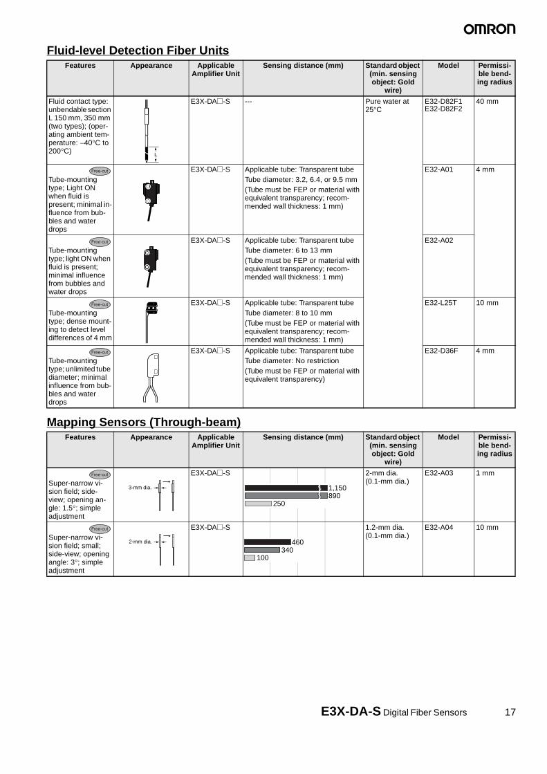
4. Teaching the Threshold Value (SET Mode)
* There are four methods that can be used for teaching, as described below. Use the method most suitable for the application.
* An error has occurred if OVER, LO, or NEAR is displayed on the sub-display. Repeat the operation from the beginning.
4-1. Setting the Threshold at Maximum Sensitivity
The threshold can be set at the maximum sensitivity. This method is ideal when using a Through-beam Fiber Unit to detect workpieces so that detection is not influenced to any great degree by dust and other environmental factors.
4-2. Teaching a Through-beam Fiber Unit without a Workpiece
A value about 6% less than the incident light level can be set as the threshold value. This method is ideal when detecting very small dif-ferences in light level, such as when detecting very fine workpieces or transparent workpieces like transparent fibers.
4-3. Teaching a Reflective Fiber Unit without a Workpiece
A value about 6% greater than the incident light level can be set as the threshold value. This method is ideal when using a Reflective Fiber Unit to detect workpieces so that detection is not influenced to any great degree by dust and other environmental factors.
4-4. Teaching With and Without a WorkpieceTeaching can be performed twice, once with and once without a workpiece, and the value between the two measured value can be set as the threshold.
UP DOWN
SET
The threshold value that was set will flash twice.
Light level Threshold
FULL Threshold
The previous display will return when the setting has been completed.
Light level Threshold
Set the Mode Selector to SET.
Either for 3 s
UP DOWN
RUN
"- - - -" will be displayed.
With no workpiece:
The previous display will return when the setting has been completed.
The set thresholdvalue will flash twice.
Threshold
TECH - - - -
Light level Threshold
THRU Threshold
Either for 1 s
To RUN
Light level
SET
Set the Mode Selector to SET.
UP DOWN
UP DOWN
SET
"- - - -" will be displayed.
With no workpiece:
The previous display will return when the setting has been completed.
The set thresholdvalue will flash twice.
Light level Threshold
TECH - - - -
Light level Threshold
RFCH Threshold
Set the Mode Selector to SET.
Either for 1 s
Either for 3 s
UP DOWN
UP DOWN
Workpiece
SET
"- - - -" will be displayed.
With a workpiece:
The previous display will return when the setting has been completed.
The set thresholdvalue will flash twice.
Light level Threshold
TECH - - - -
Light level Threshold
RFCH Threshold
Set the Mode Selector to SET.
With no workpiece:.
Either for 1 s
Either for 1 s

22 E3X-DA-S Digital Fiber Sensors
5. Setting Functions in SET Mode* The default settings are shown in the transition boxes between functions.
For the E3X-DA@-S
UP DOWN
MODE
MODE
UP DOWNMODE
UP DOWNMODE
UP DOWNMODE
MODE
UP DOWNMODE
A
SET
Set the Mode Selector to SET.
Detection
Timer
Time
Display switch (To change the display method)
Standard mode
Super-high-speed mode
High-resolution mode
OFF-delay timer
Timer disabled
ON-delay timerOne-shot timer
Switch to desiredfunction.
Changes the setting.
Timer disabled.
20 to 200 ms
200 ms to 1 s
5-ms increments
1 to 20 ms 1-ms increments
100-ms increments
1 to 5 s 1-s increments
Setting range: 0 to 5,000 ms
Light Level and Threshold Display
*1
MODE keyy (To change the function of the MODE key during operation)
Power tuningtarget value
Executes a zero reset.
Executes power tuning.
Maximum powerM
Setting range: 100 to 3,900 (increments of 100)
UP DOWN
UP DOWNMODE
B
Display orientationp y (To reverse the orientation of the display.)
Up/down reversed display
Normal display
% light level
Detection status
L-PE D-BT
L-BT D-PE
The incident light level and the threshold value.
The incident light level as a percentage of thethreshold value and the threshold value.
The incident light peak level and no incident lightbottom level.(Refreshed when output turns ON or OFF.)
The min. incident light peak level and max. incidentlight bottom level, showing min. width of light levelchange. (Refreshed when output turns ON or OFF.)
Analog bar display. The current detection status isdisplayed as an analog bar. The bar will lengthenfrom the right as ON status is reached.(ON: Red; OFF: Green)
The current incident light level and the peakincident light level.
The incident light level and the channel.
(For the E3X-DA@RM-S Only)The counter value.
Light level
Fixed interval
*1 The display will be switched as shown below.
Refer to 2. Adjusting the Power (RUN Mode) on page 19.)
Teaching: Refer to 4. Teaching the Threshold Value (SET Mode) on page 21.
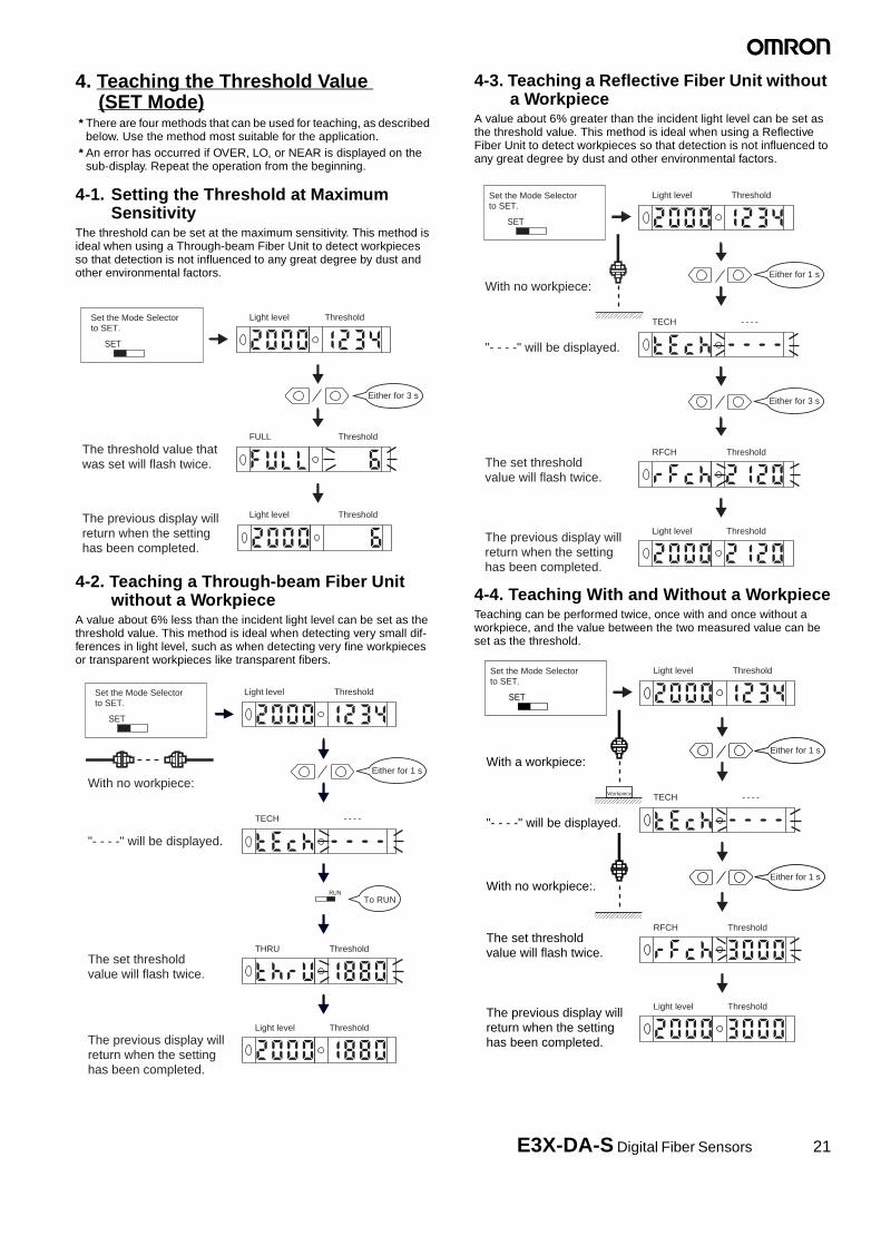
E3X-DA-S Digital Fiber Sensors 23
‘For the E3X-DA@TW-S For the E3X-DA@RM-S
UP DOWN
MODE
MODE
UP DOWNMODE
UP DOWNMODE
UP DOWNMODE
UP DOWNMODE
A
B
SET
Set the Mode Selector to SET.
Standard mode
Super-high-speed mode
Operation modeOpe a o ode
Detection
Differential edge
Differential time
(To change response speed, detection accuracy/method)
Double edgedgeSingle ed
500 µs250 µµs
1 ms500 µµs
2 ms1 ms
20 mss10 ms
200 ms100 ms100 m
Switch to desiredfunction.
Changes the setting.
Differential operation
Notdifferentialoperation
Dark ON
Light ON
Light Level andThreshold Display
See For the E3X-DA@-S on previous page.
Twin outputs (To change the output for channel 2)
Output for each channel.
the two thresholds.Self-diagnosis output
This setting is disabled if differentialoperation is set for the detection function.(Alarm outputs are always used fordifferential operation.)
(Refer to 1. Setting the Operation Mode, page 20.)
Teaching: Refer to 4. Teaching theThreshold Value (SET Mode) on page 21.
UP DOWN
MODE
MODE
UP DOWNMODE
UP DOWNMODE
UP DOWNMODE
UP DOWNMODE
UP DOWNMODE
UP DOWNMODE
A
B
Setting range: 1 to 9,999,999
SET
Set the Mode Selector to SET.
Switch to desiredfunction.
Light Level and Threshold Display
Counter
Count
(To set the counter function.)
External input memory
(Refer to instructions provided with the product.)
External input
(To change function controlledby external input.)
Counter enabled
Counter disabled
500 µs250 µs
1 ms500 µs
2 ms1 ms
20 ms10 ms
200 ms100 ms
Thru-beam, no-workpiece teachingReflective, no-workpieceteachingWith/Without-workpiece teaching
Automatic teaching
Power tuning
Light OFF
Counter reset
THRU
RFCT
2PNT
AUTO
PTUN
LOFF
CRST
Counter disabled.
Count incremented when output turns ON.Count decremented when output turns ON.
OFF
CUP
CDO
Write results to EEPROM.
Don't write results.
ON
OFF
Standard mode
Super-high-speed mode
High-resolution modeDifferential operation
Detection
Differential edge
(To change response speed, detection accuracy/method)
Double edge
Single edge
Changes the setting.
Differential operation
Not differentialoperation
Differential time
Double edge
Singleedge
See For the E3X-DA@-S on previous page.
Zero reset0RST
Teaching: Refer to 4. Teaching the Thresh-old Value (SET Mode) on page 21.

24 E3X-DA-S Digital Fiber Sensors
6. Convenient Functions
6-1. Zeroing the Digital DisplayThe incident light level on the digital display can be set to 0.
* Change the function to 0RST (zero reset) with the MODE key. The default setting is PTUN. Refer to 5. Setting Functions in SET Mode on page 22.
6-2. Locking the KeysAll key operations can be disabled.
Note:Press the DOWN key right after pressing the MODE key.
6-3. Initializing SettingsAll settings can be returned to their original default settings.
3 sMODE
3 sMODE
DOWN MODE
RUN
To reset to 0 again:
To return to original valuefor incident light level:
Set the Mode Selector to RUN
Fastory setting
3 s
Press together (see note).
MODE
MODEUP
UP
RUN
"OFF" will flash twice andkey operations will beenabled.
To release the lock:
"ON" will flash twice andkey operations will bedisabled.
LOC ON
LOC OFF
Set the Mode Selector to RUN.
Factory setting
* If a key is pressed while key operations are locked, "LOC" will flashtwice on the display to indicate thatkey operations have been disabled.
3 s
Press together (see note).
3 s
Press together (see note).
MODEMODE
UP DOWN
SET
Settings initialized. Operation canceled.
INIT NO?
Set the Mode Selector to SET.
INIT YES?
UP DOWN
3 s
Press together (see note).

E3X-DA-S Digital Fiber Sensors 25
Safety PrecautionsNote: In addition to the following precautions, please read and ob-
serve the common precautions for the instructions includedwith the product.
■ Precautions for Correct Use
Amplifier Unit
Installation
● Operation after Turning Power ONThe Amplifier Unit is ready to operate within 200 ms after the power supply is turned ON. If the Sensor and load are connected to power supplies separately, be sure to turn ON the power supply to the Sen-sor first.
Mounting
● Connecting and Disconnecting Connectors
Mounting Connectors1. Insert the Master or Slave Connector into the Amplifier Unit until it
clicks into place.
2. Attach the protector seals (provided as accessories) to the sides of master and slave connectors that are not connected.
Note:Attach the seals to the sides with grooves
Removing Connectors1. Slide the slave Amplifier Unit(s) for which the Connector is to be
removed away from the rest of the group.2. After the Amplifier Unit(s) has been separated, press down on the
lever on the Connector and remove it. (Do not attempt to remove Connectors without separating them from other Amplifier Units first.)
● Joining and Removing Amplifier Units
Joining Amplifier Units1. Mount the Amplifier Units one at a time onto the DIN track.
2. Slide the Amplifier Units together, line up the clips, and press the Amplifier Units together until they click into place.
Separating Amplifier UnitsSlide Amplifier Units away from each other, and remove from the DIN track one at a time. (Do not attempt to remove Amplifier Units from the DIN track without separating them first.)
Note 1. The specifications for ambient temperature will vary accord-ing to the number of Amplifier Units used together. For de-tails, refer to Ratings/Characteristics.
2. Always turn OFF the power supply before joining or separat-ing Amplifier Units.
● Mounting the End Plate (PFP-M)An End Plate should be used if there is a possibility of the Amplifier Unit moving, e.g., due to vibration. If a Mobile Console is going to be mounted, connect the End Plate in the direction shown in the follow-ing diagram.
● Mounting the Mobile Console HeadLeave a gap of at least 20 mm between the nearest Amplifier Unit and the Mobile Console head.
Insert
Seal Seal
Press down
Remove
Lever
Click into place
End Plate
20 mm

26 E3X-DA-S Digital Fiber Sensors
● Fiber ConnectionThe E3X Amplifier Unit has a lock button for easy connection of the Fiber Unit. Connect or disconnect the fibers using the following pro-cedures:
1. ConnectionOpen the protective cover, insert the fibers according to the fiber insertion marks on the side of the Amplifier Unit, and lower the lock button.
Fibers with E39-F9 Attachment
Fibers That Cannot Be Free-Cut (with Sleeves)
2. Disconnecting FibersRemove the protective cover and raise the lock button to pull out the fibers.
Note 1. To maintain the fiber properties, confirm that the lock is re-leased before removing the fibers.
2. Be sure to lock or unlock the lock button within an ambient temperature range between �10�C and 40�C.
Adjustments
● Mutual Interference Protection FunctionThere may be some instability in the digital display values due to light from other sensors. If this occurs, decrease the sensitivity (i.e., decrease the power or increase the threshold) to perform stable detection.
● EEPROM Writing ErrorIf the data is not written to the EEPROM correctly due to a power fail-ure or static-electric noise, initialize the settings with the keys on the Amplifier Unit. ERR/EEP will flash on the display when a writing error has occurred.
● Optical CommunicationsSeveral Amplifier Units can be slid together and used in groups. Do not, however, slide the Amplifier Units or attempt to remove any of the Amplifier Units during operation.
Other Precautions
● Protective CoverAlways keep the protective cover in place when using the Amplifier Unit.
● Mobile ConsoleUse the E3X-MC11-S Mobile Console for the E3X-DA-S-series Amplifier Units. Other Mobile Consoles, such as the E3X-MC11, cannot be used.
Lock button
Fiber
Fiber insertion mark
LockedUnlocked
Insertion position
Protective cover
9 mm
Fiber Unit9 mm
13 mm
9 mm
13 mm
Locked Unlocked
Protective cover

E3X-DA-S Digital Fiber Sensors 27
Dimensions
■ Amplifier Units
Amplifier Units with Cables
Main display Sub-displayVinyl-insulated round cableStandard length: 2 m*
Round ( ): Power tuning indicatorOblong ( ): Operation indicator for channel 2
3.4
10
Two, 2.4 dia.
4.5
5.65
3.9×3=11.7
12.15
15.1
32.8
3.25
29.8
3.9×3=11.7
4.370
32
12.59.9
16
3.4 4.4
34.8
28.1
1628.116
18.7
44.3
Two, M3
E3X-DA11-SE3X-DA41-SE3X-DAG11-SE3X-DAG41-SE3X-DAB11-SE3X-DAB41-SE3X-DA11RM-SE3X-DA41RM-SE3X-DA11TW-SE3X-DA41TW-S
Operation indicator
With Mounting Bracket Attached
The Mounting Bracket can also be used on this side.
Hole for optical communications
Mounting Bracket (E39-L143)SUS304 stainless steelTwo, 3.2 dia. holes
Mounting Holes
*Cable Specifications
A 4-dia., 4-conductor (conductor cross-sectional area: 0.2 mm2; insulation diameter: 1.1 mm)
E3X-DA11-S/DA41-S/DAG11-S/DAG41-S/DAB11-S/DAB41-S
E3X-DA11TW-S/DA41TW-S/ DA11RM-S/DA41RM-S
A 4-dia., 3-conductor (conductor cross-sectional area: 0.2 mm2; insulation diameter: 1.1 mm)

28 E3X-DA-S Digital Fiber Sensors
Amplifier Units with Connectors
■ Amplifier Unit Connectors
Master Connectors
3.4
3.9×3=11.75
12.15
15.1
32.8
3.25
29.8
3.9×3=11.7
4.370
8.1
32
12.959.9
16
34.8
28.1
18.7
44.3
3.4 4.4
16
Two, M3
10
Two, 2.4 dia.
4.5
5.65
Connector
Dia. A*2
1628.1
E3X-DA6-SE3X-DA8-SE3X-DAG6-SE3X-DAG8-SE3X-DAB6-SE3X-DAB8-SE3X-DA6RM-SE3X-DA8RM-SE3X-DA6TW-SE3X-DA8TW-S
With Mounting Bracket Attached
Hole for optical communications
Mounting Bracket (E39-L143)SUS304 stainless steel
Two, 3.2 dia. holes
Mounting Holes
*1 The Mounting Bracket can also be used on this side.*2 Cable Diameters
Main display Sub-display
Round ( ): Power tuning indicatorOblong ( ): Operation indicator for channel 2
Operation indicator
A*1E3X-CN11 (3 conductors)E3X-CN21 (4 conductors)E3X-CN22 (2 conductors)
4.0-mm dia.
E3X-CN12 (1 conductor)2.6-mm dia.
14.4
2.6
6
2.9
10
0.8 8.4
6.810.7
30±2
4 dia.
10±2
4
15.1
6
*
*E3X-CN11: A 4-dia., 3-conductor, vinyl-insulated round cable (conductor cross-sectional area: 0.2 mm2; insulation diameter: 1.1 mm) is used.
E3X-CN21: A 4-dia., 4-conductor, vinyl-insulated round cable (conductor cross-sectional area: 0.2 mm2; insulation diameter: 1.1 mm) is used.
2000
E3X-CN11E3X-CN21
+500
50+50

E3X-DA-S Digital Fiber Sensors 29
Slave Connectorss
■ Mobile Console
14.4
2.6
3
6
2.9
10
0.8 8.4
6.810.7
2,000
50
30±2
E3X-CN12: 2.6 dia.E3X-CN22: 4 dia.
10±2
4
15.1
6
*
+50
+500
E3X-CN12E3X-CN22
*E3X-CN12: A 2.6-dia., single-conductor, vinyl-insulated round cable (conductor cross-sectional area: 0.2 mm2; insulation diameter: 1.1 mm) is used.
E3X-CN22: A 4-dia., 2-conductor, vinyl-insulated round cable (conductor cross-sectional area: 0.2 mm2; insulation diameter: 1.1 mm) is used.
136
50
52.822Optical communications connection indicator
Sensoroperationindicator Main display
Sub-display
RIGHT key
ESC/PWR key
Operation keys
ENT key
LEFT key
UP key
DOWN key
20
28.813.2
31.2
9.9
27.7
17.3
1.2 5.112.3
36.751.3
5.6
24.330.3
31.8 16.313.1(38.2)
10
AC adapter jack
Communications jack
Menu indicators
Channel indicator
M5 ball plunger
Battery indicators
Channel buttons
Optical communi-cations position
Communications jack
E3X-MC11-S
Mobile Console Mobile Console Head

30 E3X-DA-S Digital Fiber Sensors

E3X-DA-S Digital Fiber Sensors 31

32
In the interest of product improvement, specifications are subject to change without notice.
ALL DIMENSIONS SHOWN ARE IN MILLIMETERS.To convert millimeters into inches, multiply by 0.03937. To convert grams into ounces, multiply by 0.03527.
Cat. No. E336-E1-01
OMRON CorporationIndustrial Automation Company
Application Sensors DivisionSensing Devices and Components Division H.Q.Shiokoji Horikawa, Shimogyo-ku,Kyoto, 600-8530 JapanTel: (81)75-344-7068/Fax: (81)75-344-7107
Printed in Japan0103-2M (0103) (O)