Digital Fiber Amplifier E3X-DA-N - OMRON Industrial · PDF file ·...
30
1 CSM_E3X-DA-N_DS_E_7_2 Digital Fiber Amplifier E3X-DA-N The Ultimate Fiber Amplifier for Maximum Ease of Use and High Performance Be sure to read Safety Precautions on page 23. UL991* * UL certification including UL 991 testing and evaluation • Applicable standards: UL 3121-1 • Additional application testing and evaluations standards: UL 991 and SEMI S2-0200S Note: Manufacturing of the E3X-DA@TW Series was discontinued at the end of March 2012. Manufacture of the E3X-DA11-N/DA41-N/DA11D/DA6/DA8/DA6D will be discontinued in March 2017. Features Models with New Connector System Reduces Wiring, Saves Space, and Makes Maintenance Easier In Amplifiers with wire-saving connectors, the power supply is distributed to 1-conductor slave connectors through a 3- conductor master connector. This design has three major advantages. 1. Wiring time is significantly reduced. 2. Relay connectors are unnecessary, so wiring takes up less space and costs are reduced. 3. Storage and maintenance are simpler because it isn't necessary to distinguish between master connector and slave connectors on the Amplifier. Super Digital Display with Auto Power Control (APC) Circuit The passage of time causes the intensity of the Sensor's light- emitting LED elements to deteriorate, which may make stable detection impossible. The E3X-DA-N is the first series of Fiber Sensors to use an Auto Power Control (APC) circuit. This achieves strict detection by eliminating fluctuation in the digital value and is ideal for subtle detection such as stable detection of liquid- crystal glass. First in the Industry Patent Pending Master connector Simplified Connector Design Slave connector Up to 16 Amplifiers can be connected. Power supply pin Optical communi- cations First in the Industry Incident level Time Threshold 3000 Unstable detection Incident level Time 3000 Stable detection Previous Digital Fiber Amplifiers E3X-DA-N Series Threshold
Transcript of Digital Fiber Amplifier E3X-DA-N - OMRON Industrial · PDF file ·...

1
CSM_E3X-DA-N_DS_E_7_2
Digital Fiber Amplifier
E3X-DA-N
The Ultimate Fiber Amplifier for Maximum Ease of Use and High Performance
Be sure to read Safety Precautions on page 23. UL991*
*UL certification including UL 991 testing and evaluation • Applicable standards: UL 3121-1 • Additional application testing and evaluations standards: UL 991 and SEMI S2-0200S
Note: Manufacturing of the E3X-DA@TW Series was discontinued at the end of March 2012.Manufacture of the E3X-DA11-N/DA41-N/DA11D/DA6/DA8/DA6D will be discontinued in March 2017.
Features
Models with New Connector System Reduces Wiring, Saves Space, and Makes Maintenance Easier
In Amplifiers with wire-saving connectors, the power supply is distributed to 1-conductor slave connectors through a 3-conductor master connector. This design has three major advantages. 1. Wiring time is significantly reduced.2. Relay connectors are unnecessary, so wiring takes up less
space and costs are reduced. 3. Storage and maintenance are simpler because it isn't
necessary to distinguish between master connector and slave connectors on the Amplifier.
Super Digital Display with Auto Power Control (APC) Circuit
The passage of time causes the intensity of the Sensor's light-emitting LED elements to deteriorate, which may make stable detection impossible. The E3X-DA-N is the first series of Fiber Sensors to use an Auto Power Control (APC) circuit. This achieves strict detection by eliminating fluctuation in the digital value and is ideal for subtle detection such as stable detection of liquid-crystal glass.
First in the Industry Patent Pending
Master connector
Simplified Connector Design
Slave connector
Up to 16 Amplifiers can be connected.
Power supply pin
Optical communi-cations
First in the Industry
Incident level
Time
Threshold
3000
Unstable detection
Incident level
Time
3000
Stable detection
Previous Digital Fiber Amplifiers
E3X-DA-N Series Threshold

E3X-DA-N
2
Power Consumption Reduced by As Much As 70%Power consumption is reduced by as much as 70% from 1800 mW to 600 mW (when the digital display is OFF).
Digital Display Can Be Turned OFF or Dimmed during OperationWhen the digital display is viewed infrequently during operation, current consumption can be reduced by dimming the display or turning it OFF entirely.(Eco-mode can be set from the Mobile Console only.)
New Generation of Mobile Consoles the Size of Cellular Phones. Further Developing the Ultimate Power of Fiber Amplifiers.
Previous model E3X-DA-N(with digital display OFF)
600 mW
1800 mW
This eco-label is displayed on products that meet environmental standards established by OMRON.
Eco-mode
Head
Function indicatorsection
Light intensity monitor
Channel setting section
Threshold
Operation keys
Battery monitor
Optical communications
Channel 1
Channel 2
Channel 3
Channel 4
Channel 5
NewConcept
Patent Pending
Flash the Sensor head and display the amplifier channels during operation.Even if the Amplifier and Sensor head are separated during operation, it is still possible to flash the Sensor head and display the amplifier channels.
Remote Setting and Adjustment Perform settings, teaching, and fine adjustments at the end of the Fiber Unit.
Display the light intensity and threshold at the same time.
Previously, settings and teaching could be performed only on the Amplifier. Now, however, using a Mobile Console enables these operations at the end of the fiber. Strict adjustments can be made while checking the workpiece position.
With group teaching, teach multiple amplifiers simultaneously.
Eliminate inconsistency by using group zero reset.
The tedious teaching that had to be performed separately for each Amplifier can now be performed for several Amplifiers at once using the Mobile Console.
The group zero reset function can simultaneously reset the digital displays of multiple Amplifiers to 0. This function is useful to minimize variation between Amplifier values.
Group teaching

E3X-DA-N
3
Ordering Information
AmplifiersPre-wired Amplifiers
*1. For details, refer to page 6. *2. Manufacturing of the E3X-DA@TW Series was discontinued at the end of March 2012.
Manufacture of the E3X-DA11-N/DA41-N/DA11D will be discontinued in March 2017.
Amplifiers with Standard Connectors
*1. For details, refer to page 6. *2. Manufacturing of the E3X-DA@TW Series was discontinued at the end of March 2012.
Manufacture of the E3X-DA6/DA8/DA6D will be discontinued in March 2017.
Type Appearance Control outputModel
NPN output PNP outputStandard models ON/OFF output E3X-DA11-N 2M *2 E3X-DA41-N 2M *2
Monitor-output models• ON/OFF output• Monitor output
E3X-DA21-N 2M E3X-DA51-N 2M
Mark-detecting models (blue LED)
ON/OFF output
E3X-DAB11-N 2M E3X-DAB41-N 2MMark-detecting models (green LED) E3X-DAG11-N 2M E3X-DAG41-N 2MInfrared models E3X-DAH11-N 2M E3X-DAH41-N 2MDifferential-output model *1 E3X-DA11D 2M *2 ---
Water-resistant models E3X-DA11V 2M E3X-DA41V 2M
Twin-output models E3X-DA11TW 2M *2 E3X-DA41TW 2M *2
Type Appearance Applicable Connector (order separately) Control output
ModelNPN output PNP output
Standard modelsMaster E3X-CN11
ON/OFF output E3X-DA6 *2 E3X-DA8 *2Slave E3X-CN12
Monitor-output modelsMaster E3X-CN21 • ON/OFF output
• Monitor outputE3X-DA7 E3X-DA9
Slave E3X-CN22Mark-detecting models (Blue LED)
Master E3X-CN11
ON/OFF output
E3X-DAB6 E3X-DAB8Slave E3X-CN12
Mark-detecting models (Green LED)
Master E3X-CN11E3X-DAG6 E3X-DAG8
Slave E3X-CN12
Infrared modelsMaster E3X-CN11
E3X-DAH6 E3X-DAH8Slave E3X-CN12
Differential-output model *1
Master E3X-CN11E3X-DA6D *2 ---
Slave E3X-CN12
Water-resistant models (M8 connector)
XS3F-M421-40@-AXS3F-M422-40@-A
E3X-DA14V E3X-DA44V
Twin-output models
Master E3X-CN21
E3X-DA6TW *2
E3X-DA8TW *2
Slave E3X-CN22

E3X-DA-N
4
Amplifier Connectors (Order Separately) Note: Seal provided as accessory.
Sensor I/O Connectors (Order Separately)
Type Appearance Cable length No. of conductors Model
Master Connector
2 m
3 E3X-CN11
4 E3X-CN21
Slave Connector
1 E3X-CN12
2 E3X-CN22
Size Cable specifications Appearance Cable type Model
M8 Standard cable
2 m
4-wire connection
XS3F-M421-402-A
5 m XS3F-M421-405-A
2 m XS3F-M422-402-A
5 m XS3F-M422-405-A
Combining Amplifiers and Connectors (Basically Amplifiers and Connectors are sold separately.)Refer to the following tables when placing an order.
When Using 5 Amplifiers
Amplifiers Applicable Connectors (Order Separately)Type NPN PNP Master Connector Slave Connector
Standard models E3X-DA6 E3X-DA8
+E3X-CN11 E3X-CN12
Mark-detecting modelsE3X-DAB6 E3X-DAB8E3X-DAG6 E3X-DAG8
Infrared models E3X-DAH6 E3X-DAH8Differential-output model E3X-DA6D ---Monitor-output models E3X-DA7 E3X-DA9
E3X-CN21 E3X-CN22Twin-output models E3X-DA6TW E3X-DA8TW
Amplifiers (5 Units) + 1 Master Connector 4 Slave Connectors
Straight connector
L-shaped connector

E3X-DA-N
5
Mobile Console (Order Separately)
Accessories (Order Separately)Mounting Brackets
*When using a Through-beam Fiber Unit, order one Bracket for the Receiver and one for the Emitter.
Appearance Model Remarks
(model number of set)E3X-MC11
Mobile Console with head, cable, and AC adapter provided as accessories.Power supply method: chargeable battery
E3X-MC11-C1 Mobile Console
E3X-MC11-H1 Head
E39-Z12-1 Cable (1.5 m)
Appearance Applicable model Model Quantity Remarks
E3X-DA-N Series E39-L143
1 ---
E3X-DA@V E39-L148
Operating Instructions Sticker
End Plate
Model Remarks
E39-Y1Attach near the Sensor.Refer to page 25.
Appearance Model Quantity
PFP-M 1

E3X-DA-N
6
Ratings and Specifications
AmplifiersPre-wired Amplifiers
TypeStandard models
Monitor-output models
Mark-detecting modelsInfrared models
Water-resistant models
Twin-output models
Outputtype
NPNoutput
E3X-DA11-N
E3X-DA21-N
E3X-DAB11-N
E3X-DAG11-N
E3X-DAH11-N
E3X-DA11V
E3X-DA11TW
ItemPNP
outputE3X-DA41-N
E3X-DA51-N
E3X-DAB41-N
E3X-DAG41-N
E3X-DAH41-N
E3X-DA41V
E3X-DA41TW
Light source (wavelength)
Red LED (660 nm)Blue LED (470 nm)
Green LED (525 nm)
Infrared LED (870 nm)
Red LED (660 nm)
Power supply voltage 12 to 24 VDC±10%, ripple (p-p) 10% max.
Power consumptionNormally: 960 mW max. (current consumption: 40 mA max. at power supply voltage of 24 VDC)Eco Mode: 720 mW max. (current consumption: 30 mA max. at power supply voltage of 24 VDC)Digital display not lit: 600 mW max. (current consumption: 25 mA max. at power supply voltage of 24 VDC)
Con-trol output
ON/OFF output
Load current: 50 mA (residual voltage (NPN/PNP): 1 V max.,Open collector (NPN or PNP output, depending on the model) Light ON/Dark ON selectable
Monitor output
---Load 1 to 5 VDC, 10 kΩ min.
---
Protection circuitPower supply reverse polarity, Output short-circuit protection, Mutual interference prevention (supported for up to 10 Units)
Re-sponse time
Super-high-speed mode
0.25 ms for operation and reset respectively
0.5 ms for operation and reset respectively
Standard mode
1 ms for operation and reset respectively2 ms for operation and reset
Super-long-distance mode
4 ms for operation and reset respectively
7 ms for operation and reset respectively
Sensitivity setting Teaching or manual method
Func-tions
Timer func-tion
OFF-delay timer: 0 to 200 ms, 1 to 20 ms (set in 1-ms units); 20 to 200 ms (set in 5-ms units)Using Mobile Console: OFF delay, ON delay, or one shot (selectable)
Automatic power con-trol (APC)
Fiber-optic current digital control
--- Fiber-optic current digital control
Zero-reset Negative values can be displayed.
Initial reset Settings can be returned to defaults as required.
Monitor fo-cus
---
Upper and lower limits can be set as required for every 100 digital values.
---
IndicatorsOperation indicator (orange), 7-segment digital incident level display (red), 7-segment digital incident level percentage display (red), threshold and excess gain 2-color double bar indicators (green and red), 7-segment digital threshold display (red)
Display timing Switching between normal/peak-hold/bottom-hold possible
Display orientation Switching between normal/reverse possible
Optical axis adjust-ment
Optical axis adjustment possible (hyper-flashing function)
Ambient illumination(receiver side)
Incandescent lamp: 10,000 lx max.Sunlight: 20,000 lx max.
For dimensions, refer to page 26 to 29.

E3X-DA-N
7
Amplifiers with Connectors(Specifications different to those for Pre-wired Amplifiers)
*The dielectric strength for water-resistant models is 500 VAC at 50/60 Hz for 1 min.
Ambient temperature
Operating:Groups of 1 to 3 Amplifiers: −25 to 55°CGroups of 4 to 11 Amplifiers: −25 to 50°CGroups of 12 to 16 Amplifiers: −25 to 45°CStorage:−30 to 70°C (with no icing or condensation)
Ambient humidity Operating and storage: 35% to 85% (with no condensation)
Insulation resistance 20 MΩ min. (at 500 VDC)
Dielectric strength 1,000 VAC at 50/60 Hz for 1 min
Vibration resistance (destruction)
10 to 55 Hz with a 1.5-mm double amplitude for 2 h each in X, Y and Z directions
Shock resistance (destruction)
500m/s2, for 3 times each in X, Y and Z directions
Degree of protection IEC IP50 (with Protective Cover attached)
IEC IP66 (with Protective Cover attached)
IEC IP50 (with Protective Cover attached)
Connection method Pre-wired (standard cable length: 2 m)
Weight (packed state) Approx. 100 g Approx. 110 g Approx. 100 g
Materi-al
Case Polybutylene terephthalate (PBT)
Cover Polycarbonate Polyethersulfone
Accessories Instruction sheet
TypeStandard models
Monitor-out-put models
Mark-detecting modelsInfraredmodels
Water-resistant models*
Twin-output models
Outputtype
NPNoutput
E3X-DA6 E3X-DA7 E3X-DAB6 E3X-DAG6 E3X-DAH6E3X-DA14V
E3X-DA6TW
ItemPNP
outputE3X-DA8 E3X-DA9 E3X-DAB8 E3X-DAG8 E3X-DAH8
E3X-DA44V
E3X-DA8TW
Connection method Standard connector M8 connectorStandard connector
Weight (packed state) Approx. 55 g Approx. 65 g Approx. 55 g
TypeStandard models
Monitor-output models
Mark-detecting modelsInfrared models
Water-resistant models
Twin-output models
Outputtype
NPNoutput
E3X-DA11-N
E3X-DA21-N
E3X-DAB11-N
E3X-DAG11-N
E3X-DAH11-N
E3X-DA11V
E3X-DA11TW
ItemPNP
outputE3X-DA41-N
E3X-DA51-N
E3X-DAB41-N
E3X-DAG41-N
E3X-DAH41-N
E3X-DA41V
E3X-DA41TW
ConnectorsItem Model E3X-CN11/21/22 E3X-CN12
Rated current 2.5 A
Rated voltage 50 V
Contact resistance20 mΩ max. (20 mVDC max., 100 mA max.)The figure is for connection to the Amplifier and the adjacent Connector. It does not include the conductor resistance of the cable.
No. of insertions (durability)
50 timesThe figure for the number of insertions is for connection to the Amplifier and the adjacent Connector.
MaterialHousing Polybutylene terephthalate (PBT)
Contacts Phosphor bronze/gold-plated nickel
Weight (packed state) Approx. 55 g Approx. 25 g
Mobile ConsoleItem Model E3X-MC11
Power supply voltage
Charged with AC adapter
Connection method
Connected via adapter
Weight(packed state)
Approx. 580 g(Console only: 120 g)
Refer to Instruction Manual provided with the Mobile Console for details.

E3X-DA-N
8
Digital Fiber Amplifiers with Differential Outputs (E3X-DA11D/E3X-DA6D)Characteristics of Applicable Fiber Units Through-beam Fiber Units
*1. These values are for sensing objects that are moving.*2. This value applies when the response time is set to 3 to 11. An object of this value is detectable if the temperature changes within the range of ambient operating
temperature. (The value is for sensing objects that are moving.)*3. The values given in the above table are those that can be detected at a digital value of 1,000 in each sensing area.
Reflective Fiber Units
*1. Sensing distances are given for white paper.*2. These values are for sensing objects that are moving.*3. This value applies when the response time is set to 3 to 11. An object of this value is detectable if the temperature changes within the range of ambient operating
temperature. (The value is for sensing objects that are moving.)
Differences Compared with E3X-DA-N Amplifier
Sensing distance (mm) (The figures in parentheses apply when using the 39-F1 Lens Unit.)Standard object
(mm) *1(min. sensing
object *2: opaque)
Sensitivity selection HIGH LOW
11-level setting 1 2 3 to 11 1 2 3 to 11
Fiber Unit
Responsetime
270 or 570 µs
0.5 or 1 ms1 to 200 msor 2 to 400 ms
270 or 570 µs
0.5 or 1 ms1 to 200 msor 2 to 400 ms
E32-T11R 240 (1680) 280 (1960) 370 (2590) 140 (980) 180 (1260) 240 (1680)1 dia. (0.01 dia.)
E32-T21R 50 60 80 30 40 50
E32-T16WR 580 690 910 350 450 580 (0.3 dia.) *1
E32-T16PR 380 450 600 230 290 380 (0.2 dia.) *2
Sensing distance (mm) *1Standard object
(mm) *2(min. sensing
object *3: opaque)
Sensitivity selection HIGH LOW
11-level setting 1 2 3-11 1 2 3-11
Fiber Unit
Responsetime
270 or 570 µs
0.5 or 1 ms1 to 200 ms or 2 to 400 ms
270 or 570 µs
0.5 or 1 ms1 to 200 msor 2 to 400 ms
E32-D11R 80 90 120 45 60 80150 × 150(0.01 dia.)
E32-D21R 13 15 20 7 10 13 25 × 25 (0.01 dia.)
Differential-output Models (Edge-detection Models)
Type Pre-wired Wire-saving connector
Item NPN output E3X-DA11D E3X-DA6D
Current consumption 960 mW max. (current consumption: 40 mA max. at power supply voltage of 24 VDC)
Con-troloutput
ON/OFF outputLoad current: 50 mA max., (Residual voltage: 1 V max. for NPN/PNP output)Open collectorSwitchable between Light ON (ON at edge detection) and Dark ON (OFF at edge detection)
Detection mode Switchable between single edge and double edge detection mode
Response timeSingle edge: Can be set to 270 µs, 500 µs, 1 ms, 2 ms, 4 ms, 10 ms, 20 ms, 30 ms, 50 ms, 100 ms, or 200 ms.Double edge: Can be set to 570 µs, 1 ms, 2 ms, 4 ms, 10 ms, 20 ms, 30 ms, 50 ms, 100 ms, 200 ms or 400 ms.
Func-tions
Timer functionsLight ON: OFF-delay timer, Dark ON: ON-delay timer 0 to 5 s (1 to 20 ms: 1-ms units, 20 to 200 ms: 5-ms units, 200 ms to 1 s: 100 ms, 1 to 5 s: 1-s units)
APC Yes
Zero-reset Yes (Negative values can be displayed.)
Initial reset Yes (Settings can be returned to defaults.)
Sensitivity se-lection
Yes (HIGH/LOW)
Teaching level One-point teaching level can be varied from 1% to 50% in increments of 1%
IndicatorsOperation indicator (orange), 7-segment digital incident level display (red), 7-segment digital detection level display (red)
For other information, refer to the instruction manual supplied with the product.

E3X-DA-N
9
Engineering Data (Reference Value)
E3X-DA-N/E3X-DA@V/E3X-DA@TW
Parallel Operating Range At maximum sensitivity. (Use for optical axis adjustment at installation.)Through-beam Through-beam Through-beamE32-T11L E32-T11L + E39-F1 (separately sold
Long-distance Lens Unit)E32-T12L
Through-beam Through-beam Through-beamE32-TC200 E32-TC200 + E39-F1 (separately sold
Long-distance Lens Unit)E32-T11R
Through-beam Through-beam Through-beamE32-T12R E32-T21R E32-T22R
Through-beam Through-beam Through-beamE32-T11 E32-T22B E32-T14LR
800
600
400
200
0
−200
−400
−600
−800
0.5 1.51 2 2.5 3 3.5 4Distance X (m)
High speed Super-long distanceStandard
Dis
tanc
e Y
(m
m)
X
Y
800
600
400
200
0
−200
−400
−600
−800
1 2 3 4 5
X
Y
Distance X (m)
Super-high speed
Super-long distance
Standard
Dis
tanc
e Y
(m
m)
X
Y
800
600
400
200
0
−200
−400
−600
−800
21 3 4 5Distance X (m)
High speed
Super-long distance
Dis
tanc
e Y
(m
m)
Standard
600
400
200
0
−200
−400
−600
0.4 0.8 1.2 1.6 2
X
Y
DistanceX (m)
Super-high speed
Super-long distance
Standard
Dis
tanc
e Y
(m
m) 600
400
200
0
−200
−400
−600
1 2 3 4 5
X
Y
Distance X (m)
High speedSuper-long distance
StandardDis
tanc
e Y
(m
m) 400
300
200
100
0
−100
−200
−300
−400
0.2 0.4 0.8 1.20.6 1 1.4
X
Y
DistanceX (m)
Super-high speed
Super-long distance
Standard
Dis
tanc
e Y
(m
m)
X
Y
400
300
200
100
0
−100
−200
−300
−400
0.60.2 0.4 0.8 1 1.2 1.4Distance
X (m)
Super-high speed Super-long distance
Standard
Dis
tanc
e Y
(m
m) 40
30
20
10
0
−10
−20
−30
−40
4020 80 10060 120 140 160
X
Y
Distance X (mm)
High speed Super-long distance
Standard
Dis
tanc
e Y
(m
m) 80
60
40
20
0
−20
−40
−60
−80
50 100 150 200 250 300 350
X
Y
Distance X (mm)
Super-high speed
Super-long distance
Standard
Dis
tanc
e Y
(m
m)
800
600
400
200
0
−200
−400
−600
−800
0.80.4 1.2 1.6 2 2.4
X
Y
Distance X (m)
Super-highspeed
Super-long distance
Standard
Dis
tanc
e Y
(m
m) 200
150
100
50
0
−50
−100
−150
−200
100 200 300 400 500
X
Y
Distance X (mm)
High speedSuper-long distance
Standard
Dis
tanc
e Y
(m
m) 150
100
50
0
−50
−100
−150
100 200 300 400 600500
X
Y
Distance X (mm)
Super-high speed
Super-long distance
Standard
Dis
tanc
e Y
(m
m)

E3X-DA-N
10
Through-beam Through-beam Through-beamE32-T24R E32-T81R E32-T51
Through-beam Through-beam Through-beamE32-T61 E32-T61 + E39-F1 (separately sold
Long-distance Lens Unit)E32-T22S
Through-beam Through-beam Through-beamE32-T24S E32-T16W E32-T16WR
Through-beam Through-beam Through-beamE32-T16J E32-T16J E32-T16JR
Through-beam Through-beamE32-T16P E32-T16PR
40
30
20
10
0
−10
−20
−30
−40
40 80 120 160 200
X
Y
Distance X (mm)
Super-high speed
Super-long distance
Standard
Dis
tanc
e Y
(m
m) 300
200
100
0
−100
−200
−300
100 200 400300 500 600 700 800
X
Y
DistanceX (mm)
High speed
Super-long distance
Standard
Dis
tanc
e Y
(m
m) 800
600
400
200
0
−200
−400
−600
−800
0.4 0.8 1.2 1.6 2
X
Y
DistanceX (m)
High speed Super-longdistanceStandard
Dis
tanc
e Y
(m
m)
500400
300
200
100
0
−100
−200
−300
−400−500
0.2 0.4 0.6 0.8 1 1.2
X
Y
DistanceX (m)
High speed Super-long distance
Standard
Dis
tanc
e Y
(m
m) 600
400
200
0
−200
−400
−600
1 2 3 4 5
X
Y
Distance X (m)High speed
Super-long distance
Standard
Dis
tanc
e Y
(m
m) 200
150
100
50
0
−50
−100
−150
−200
1 2 3 4 5
X
Y
Distance X (m)
High speed
Super-long distance
StandardDis
tanc
e Y
(m
m)
80
60
40
20
0
−20
−40
−60
−80
1 2 3 4 5
X
Y
DistanceX (m)High speed
Super-long distance
Standard
Dis
tanc
e Y
(m
m)
X
Y
120
80
40
0
−40
−80
−120
1 2 3 4 5
Distance X (m)
High speed
Super-long distance
Standard
Dis
tanc
e Y
(m
m)
X
Y
150
100
50
0
−50
−100
−150
1 2 3 4 5 6Distance
X (m)
Super-high speed
Super-long distance
StandardD
ista
nce
Y (
mm
)
200
150
100
50
0
−50
−100
−150
−200
1 2 3 4 5
X
Y
DistanceX (m)
High speed
Super-long distance
Standard
Dis
tanc
e Y
(m
m) 200
150
100
50
0
−50
−100
−150
−200
1 2 3 4 5
X
Y
DistanceX (m)
High speed
Super-long distance
Standard
Dis
tanc
e Y
(m
m) 150
100
50
0
−50
−100
−150
1 2 3 4 5
X
Y
DistanceX (m)
Super-high speed
Super-long distance
Standard
Dis
tanc
e Y
(m
m)
150
100
50
0
−50
−100
−150
1 2 3 54
X
Y
Distance X (m)High speed
Super-long distance
Standard
Dis
tanc
e Y
(m
m) 200
150
100
50
0
−50
−100
−150
−200
1 2 3 54
X
Y
Distance X (m)
Super-high speed Super-long distance
Standard
Dis
tanc
e Y
(m
m)

E3X-DA-N
11
Operating Range With standard sensing object at maximum sensitivity. (Use for the positioning of the object and Sensor.)Reflective Reflective ReflectiveE32-D21L E32-DC200 E32-D11R
Reflective Reflective ReflectiveE32-D12R E32-D21R E32-D22R
Reflective Reflective ReflectiveE32-D33 E32-D331 E32-D21B
Reflective Reflective ReflectiveE32-D22B E32-C31 E32-C41
30
20
10
0
−10
−20
−30
100 200 300 400
X
Y
DistanceX (mm)
High speed
Super-long distance
Standard
Dis
tanc
e Y
(m
m) 150
100
50
0
−50
−100
−150
100200 300
400500 600
X
Y
DistanceX (mm)
Super-highspeed
Super-long distanceStandard
Dis
tanc
e Y
(m
m)
5040
30
20
10
0
−10
−20
−30
−40−50
100 300200 400 500
X
Y
DistanceX (mm)
High speed Super-long distance
Standard
Dis
tanc
e Y
(m
m)
100
80
60
40
20
0
−20
−40
−60
−80−100
100300200
400 500
X
Y
DistanceX (mm)
Super-high speed Super-long distance
Standard
Dis
tanc
e Y
(m
m) 10
8
6
4
2
0
−2
−4
−6
−8−10
10 30 40 60
20 5070 80 90
X
Y
DistanceX (mm)
High speedSuper-long distance
Standard
Dis
tanc
e Y
(m
m) 10
8
6
4
2
0
−2
−4
−6
−8−10
806040
20 100
X
Y
Distance X (mm)
Super-high speedSuper-longdistance
Standard
Dis
tanc
e Y
(m
m)
8
6
4
2
0
−2
−4
−6
−8
10 20 30 40 50
X
Y
DistanceX (mm)
Super-high speed
Super-long distance
Standard
Dis
tanc
e Y
(m
m)
0.6
0.4
0.2
0
−0.2
−0.4
−0.6
1 2 3 4 5 6
X
Y
DistanceX (mm)
High speed
Super-long distance
Standard
Dis
tanc
e Y
(m
m) 20
15
10
5
0
−5
−10
−15
−20
20 40 60 80 100 120 140
X
Y
DistanceX (mm)
High speedSuper-long distance
Standard
Dis
tanc
e Y
(m
m)
20
15
10
5
0
−5
−10
−15
−20
4020
60 80 100
X
Y
DistanceX (mm)
High speed
Super-long distance
Standard
Dis
tanc
e Y
(m
m) 30
20
10
0
−10
−20
−30
20 40 60 80 100
X
Y
DistanceX (mm)High speed
Super-long distance
StandardDis
tanc
e Y
(m
m)
12
8
4
0
−4
−8
−12
1020 30 40 50 60
X
Y
DistanceX (mm)
High speed
Super-long distanceStandard
Dis
tanc
e Y
(m
m)

E3X-DA-N
12
Reflective Reflective ReflectiveE32-C42 E32-D32 E32-D14LR
Reflective Reflective ReflectiveE32-D24 E32-D24R E32-D61
Reflective Reflective ReflectiveE32-D36P1 E32-D36P1 E32-L56E@
Limited ReflectiveE32-L25L
12
8
4
0
−4
−8
−12
1020 30 40 50 60
X
Y
Distance X (mm)
High speed
Super-long distanceStandard
Dis
tanc
e Y
(m
m) 40
30
20
10
0
−10
−20
−30
−40
40 80 120 160 200 240
X
Y
DistanceX (mm)
High speed
Super-long distance
Standard
Dis
tanc
e Y
(m
m) 25
20
15
10
5
0
−5
−10
−15
−20−25
1601208040 200
Y
X
DistanceX (mm)
Super-high speed
Super-long distance
Standard
Dis
tanc
e Y
(m
m)
20
15
10
5
0
−5
−10
−15
−20
20 4060
80 100 120
Y
X
DistanceX (mm)
High speedSuper-long distance
Standard
Dis
tanc
e Y
(m
m)
Y
X108
6
4
2
0
−2
−4
−6
−8−10
10 20 30 40 50 60Distance
X (mm)
Super-high speedSuper-longdistance
Standard
Dis
tanc
e Y
(m
m) 120
80
40
0
−40
−80
−120
100 200
300
400 500
X
Y
DistanceX (mm)
High speed
Super-long distance
Standard
Dis
tanc
e Y
(m
m)
0
50
100
150
200
−200
−150
−100
−50100 200 300 400 500 600
X
Y
DistanceX (mm)
High speed Super-longdistance
Standard
Dis
tanc
e Y
(m
m)
120
80
40
0
−40
−80
−120
100 400200 300 500 600
X
Y
DistanceX (mm)
High speed Super-long distance
Standard
Dis
tanc
e Y
(m
m) 2.0
1.5
1.0
0.5
0
−0.5
−1.0
−1.5
−2.0
4 8 12 16 20 24
X
Y
DistanceX (mm)
Dis
tanc
e Y
(m
m)
1
0.5
0
−0.5
−1
2 4 6 8 10
Y
X
X
DistanceX (mm)
Dis
tanc
e Y
(m
m)

E3X-DA-N
13
E3X-DA-N
Excess Gain Ratio vs. Distance With standard sensing object at maximum sensitivity.Through-beam Reflective ReflectiveE32-TC200 E32-DC200 E32-D21L
Operating Range Hysteresis vs. Sensing Distance Repeat Accuracy vs. Sensing Distance Reflective Reflective ReflectiveE32-DC200 E32-D11L E32-DC200
Monitor Output vs. Distance (Standard Mode)Through-beam ReflectiveE32-TC200 E32-DC200
1,000500300
1005030
1053
10.50.3
0.1
Distance (m)
0 0.4 0.8 1.2 1.6 2
Super-high speed
Standard
Super-long distance
Oper-ating level
Exc
ess
gain
rat
io (
times
) 1,000500300
1005030
1053
10.50.3
0.10 100 200 300 400 500 600 700 800
Distance (mm)
Super-high speed Standard
Super-long distance
Oper-ating level
Exc
ess
gain
rat
io (
times
) 1,000500300
1005030
1053
10.50.3
0.10 50 100 150 200 250 300 350 400
Distance (mm)
Super-high speed Standard
Super-long distance
Oper-ating level
Exc
ess
gain
rat
io (
times
)
20
15
10
5
0
−5
−10
−15
−20
3020 40 50 6010
0.02-mm-dia. copper wire
0.1-mm-dia. copper wire
0.4-mm-dia. copper wire
X
φ
Y
DistanceX (mm)
Dis
tanc
e Y
(m
m)
30
25
20
15
10
5
0100 200 400300 500
Sensing object: White paperDistance Hysteresis
OFFON
Hys
tere
sis
(mm
)
Distance (mm)
Super-highspeed
Standard
Super-longdistance
10090
80
70
60
50
40
30
20
10
0 20 40 8060 100
X
ON
Sensing object: White paper
Distance X (mm)
Super-highspeed
Standard
Super-long distance
Rep
eat a
ccur
acy
(mm
)
6
5
4
3
2
1
0 50 100 150 250200 300
Distance (mm)
Mon
itor
outp
ut (
V) 6
5
4
3
2
1
0 10 3020 5040 60 9070 80 100
Distance (mm)
Mon
itor
outp
ut (
V)
E3X-DA-N
14
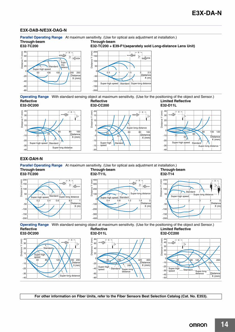
E3X-DAB-N/E3X-DAG-N
E3X-DAH-N
Parallel Operating Range At maximum sensitivity. (Use for optical axis adjustment at installation.)Through-beam Through-beamE32-TC200 E32-TC200 + E39-F1(separately sold Long-distance Lens Unit)
Operating Range With standard sensing object at maximum sensitivity. (Use for the positioning of the object and Sensor.)Reflective Reflective Limited ReflectiveE32-DC200 E32-CC200 E32-D11L
Parallel Operating Range At maximum sensitivity. (Use for optical axis adjustment at installation.)Through-beam Through-beam Through-beamE32-TC200 E32-T11L E32-T14
Operating Range With standard sensing object at maximum sensitivity. (Use for the positioning of the object and Sensor.)Reflective Reflective Limited ReflectiveE32-DC200 E32-D11L E32-CC200
For other information on Fiber Units, refer to the Fiber Sensors Best Selection Catalog (Cat. No. E353).
80
60
40
20
0
−20
−40
−60
−80
50 100 150 200 250
X
Y
DistanceX (mm)
Super-high speed
Super-longdistanceStandard
Dis
tanc
e Y
(m
m) 200
150
100
50
0
−50
−100
−150
−200
0.5 21 1.5 2.5
X
Y
DistanceX (m)
Super-high speed Super-long distanceStandard
Dis
tanc
e Y
(m
m)
40
30
20
10
0
−10
−20
−30
−40
2040
60 80 100
X
Y
DistanceX (mm)
Super-high speed
Super-long distance
Standard
Dis
tanc
e Y
(m
m) 20
15
10
5
0
−5
−10
−15
−20
2040
60 80 100
X
Y
DistanceX (mm)
Super-highspeed
Super-long distance
Standard
Dis
tanc
e Y
(m
m) 40
30
20
10
0
−10
−20
−30
−40
100 1208060
4020
X
Y
DistanceX (mm)
Super-high speed
Super-long distanceStandard
Dis
tanc
e Y
(m
m)
200
150
100
50
0
−50
−100
−150
−200
0.2 0.4 0.6 8.0 1
X
Y
DistanceX (m)
Super-high speed Super-long distanceStandardDis
tanc
e Y
(m
m) 400
300
200
100
0
−100
−200
−300
−400
0.4 0.8 1.2 1.6 2
X
Y
DistanceX (m)
Super-high speed
Super-long distance
Standard
Dis
tanc
e Y
(m
m) 200
150
100
50
0
−50
−100
−150
−200
1 2 3 4 5
X
Y
DistanceX (m)
Super-high speedSuper-long distance
Standard
Dis
tanc
e Y
(m
m)
40
30
20
10
0
−10
−20
−30
−40
40 80 120 160 200
X
Y
DistanceX (mm)
Super-highspeed
Super-long distance
Standard
Dis
tanc
e Y
(m
m) 80
60
40
20
0
−20
−40
−60
−80
80 160
240
320 400
X
Y
DistanceX (mm)
Super-high speed Super-long
distanceStandard
Dis
tanc
e Y
(m
m)
5040
30
20
10
0
−10
−20
−30
−40−50
40 80 120160
200
X
Y
DistanceX (mm)
Super-highspeed Super-long
distance
Standard
Dis
tanc
e Y
(m
m)

E3X-DA-N
15
Technical Reference (for E3X-DA-TW Twin-output Models) (In the following examples, threshold 1 is set to 3,000, and threshold 2 is set to 1,000.)
Output Patterns for Normal OperationOutputs 1 and 2 can be set to operate independently and either Light ON mode or Dark ON mode can be selected (independently) for channels 1and 2 making a total of 4 possible output patterns.
Threshold 1: Light ONThreshold 2: Light ON
Threshold 1: Dark ONThreshold 2: Light ON
Threshold 1: Light ONThreshold 2: Dark ON
Threshold 1: Dark ONThreshold 2: Dark ON
Threshold 1
Threshold 21000
0
ON
OFF
ON
OFF
Output 1
Output 2
3000
4000
Time
Inci
dent
leve
l
1000
0
ON
OFF
ON
OFF
3000
4000
Threshold 1
Threshold 2
Output 1
Output 2
TimeIn
cide
nt le
vel
1000
0
ON
OFF
ON
OFF
3000
4000
Threshold 1
Threshold 2
Output 1
Output 2
Time
Inci
dent
leve
l
1000
0
ON
OFF
ON
OFF
3000
4000
Threshold 1
Threshold 2
Output 1
Output 2
Time
Inci
dent
leve
l
Note: Output 2 is always OFF.
Output Patterns for Area SensingThis series includes models equipped with area sensing functionality, a first for Digital Fiber Amplifiers. This functionality can be used to monitor whether the incident level is inside or outside the threshold area. The 2 output patterns below are possible for this kind of operation.
ON inside threshold area
ON outside threshold area
1000
0
ON
OFF
ON
OFF
3000
4000
Threshold 1
Threshold 2
Output 1
Output 2
Time
Inci
dent
leve
l
1000
0
ON
OFF
ON
OFF
3000
4000
Threshold 1
Threshold 2
Output 1
Output 2
Time
Inci
dent
leve
l
E3X-DA-N
16
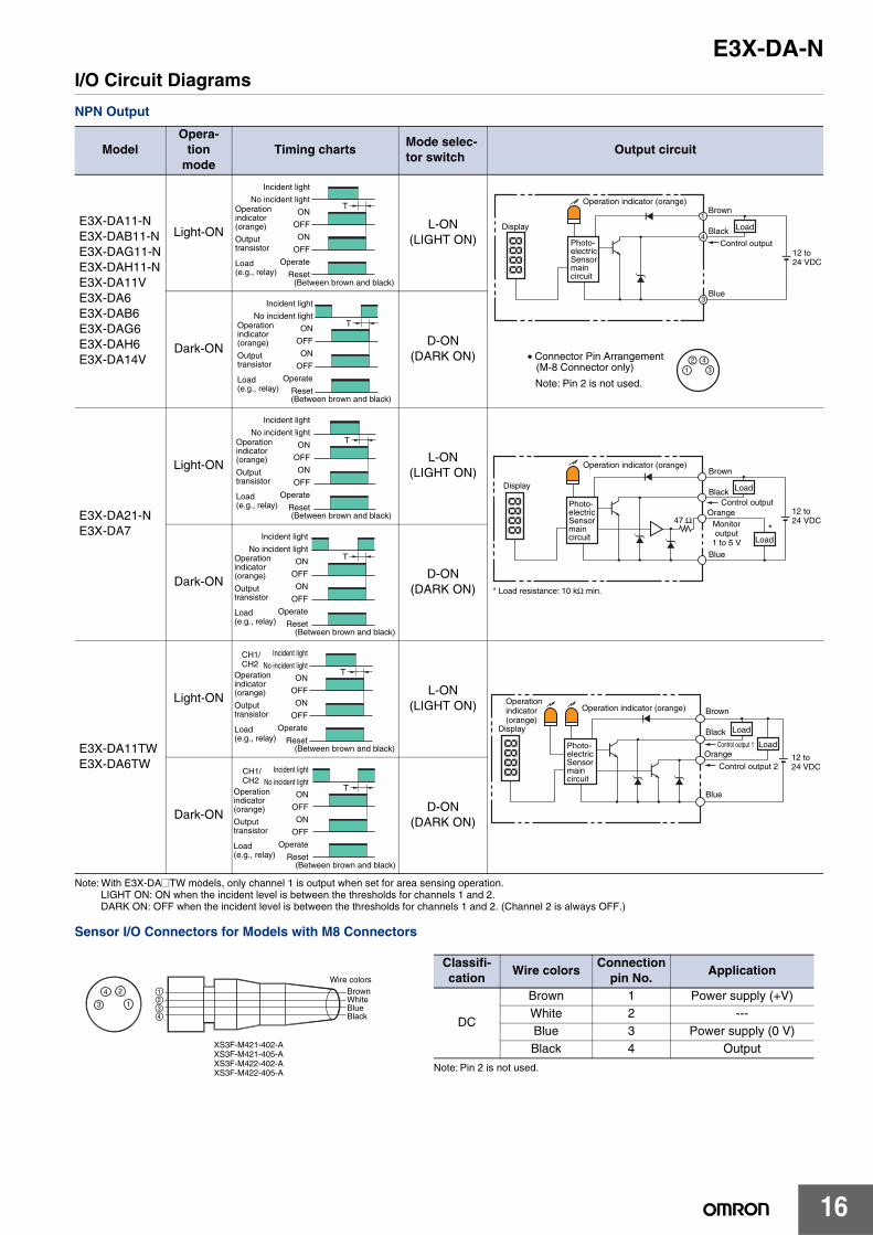
I/O Circuit Diagrams
NPN Output
Note: With E3X-DA@TW models, only channel 1 is output when set for area sensing operation.LIGHT ON: ON when the incident level is between the thresholds for channels 1 and 2.DARK ON: OFF when the incident level is between the thresholds for channels 1 and 2. (Channel 2 is always OFF.)
Sensor I/O Connectors for Models with M8 Connectors
ModelOpera-
tion mode
Timing chartsMode selec-tor switch
Output circuit
E3X-DA11-NE3X-DAB11-NE3X-DAG11-NE3X-DAH11-NE3X-DA11VE3X-DA6E3X-DAB6E3X-DAG6E3X-DAH6E3X-DA14V
Light-ONL-ON
(LIGHT ON)
Dark-OND-ON
(DARK ON)
E3X-DA21-NE3X-DA7
Light-ONL-ON
(LIGHT ON)
Dark-OND-ON
(DARK ON)
E3X-DA11TWE3X-DA6TW
Light-ONL-ON
(LIGHT ON)
Dark-OND-ON
(DARK ON)
Incident light
No incident light
ON
OFF
ON
OFF
Operate
Reset
Operation indicator (orange)
(Between brown and black)
Output transistor
Load (e.g., relay)
T
Load
Operation indicator (orange)Brown
1
3
4Black
Blue
Control output12 to 24 VDC
Display
• Connector Pin Arrangement (M-8 Connector only)
Note: Pin 2 is not used.1
2 43
Photo-electric Sensor main circuit
T
Incident light
No incident light
ON
OFF
ON
OFF
Operate
Reset(Between brown and black)
Operation indicator (orange)
Output transistor
Load (e.g., relay)
T
Incident light
No incident light
ON
OFF
ON
OFF
Operate
Reset(Between brown and black)
Operation indicator (orange)
Output transistor
Load (e.g., relay)
Orange
*
* Load resistance: 10 kΩ min.
47 Ω
Load
Operation indicator (orange)Brown
Black
Blue
Control output12 to 24 VDC
Display
Photo-electric Sensor main circuit
Load
Monitor output
1 to 5 V
T
Incident light
No incident light
ON
OFF
ON
OFF
Operate
Reset(Between brown and black)
Operation indicator (orange)
Output transistor
Load (e.g., relay)
T
CH1/CH2
Incident light
No incident light
ON
OFF
ON
OFF
Operate
Reset(Between brown and black)
Operation indicator (orange)
Output transistor
Load (e.g., relay)
OrangeLoad
Operation indicator (orange) Brown
Black
Blue
Control output 1
12 to 24 VDC
Display
Photo-electric Sensor main circuit
Load
Operation indicator (orange)
Control output 2
T
CH1/CH2
Incident light
No incident light
ON
OFF
ON
OFF
Operate
Reset(Between brown and black)
Operation indicator (orange)
Output transistor
Load (e.g., relay)
24
13
1234
BrownWhiteBlueBlack
Wire colors
XS3F-M421-402-AXS3F-M421-405-AXS3F-M422-402-AXS3F-M422-405-A Note: Pin 2 is not used.
Classifi-cation
Wire colorsConnection
pin No.Application
DC
Brown 1 Power supply (+V)White 2 ---Blue 3 Power supply (0 V)Black 4 Output

E3X-DA-N
17
PNP Output
Note: With E3X-DA@TW models, only channel 1 is output when set for area sensing operation.LIGHT ON: ON when the incident level is between the thresholds for channels 1 and 2.DARK ON: OFF when the incident level is between the thresholds for channels 1 and 2. (Channel 2 is always OFF.)
Sensor I/O Connectors for Models with M8 Connectors
ModelOpera-
tion mode
Timing chartsMode selec-tion switch
Output circuit
E3X-DA41-NE3X-DAB41-NE3X-DAG41-NE3X-DAH41-NE3X-DA41VE3X-DA8E3X-DAB8E3X-DAG8E3X-DAH8E3X-DA44V
Light-ONL-ON
(LIGHT ON)
Dark-OND-ON
(DARK ON)
E3X-DA51-NE3X-DA9
Light-ONL-ON
(LIGHT ON)
Dark-OND-ON
(DARK ON)
E3X-DA41TWE3X-DA8TW
Light-ONL-ON
(LIGHT ON)
Dark-OND-ON
(DARK ON)
T
(Between blue and black)
Incident light
No incident light
ON
OFF
ON
OFF
Operate
Reset
Operation indicator (orange)
Output transistor
Load (e.g., relay)
1
4
3
1
2 43
Load
Operation indicator (orange) Brown
Black
Blue
Control output12 to 24 VDC
Display
Photo-electric Sensor main circuit
• Connector Pin Arrangement (M-8 Connector only)
Note: Pin 2 is not used.
T
(Between blue and black)
Incident light
No incident light
ON
OFF
ON
OFF
Operate
Reset
Operation indicator (orange)
Output transistor
Load (e.g., relay)
T
(Between blue and black)
Incident light
No incident light
ON
OFF
ON
OFF
Operate
Reset
Operation indicator (orange)
Output transistor
Load (e.g., relay)
Orange *
* Load resistance: 10 kΩ min.
47 Ω
Load
Operation indicator (orange)Brown
Black
Blue
Control output12 to 24 VDC
Display
Photo-electric Sensor main circuit
LoadMonitor output 1 to 5 V
T
(Between blue and black)
Incident light
No incident light
ON
OFF
ON
OFF
Operate
Reset
Operation indicator (orange)
Output transistor
Load (e.g., relay)
T
CH1/CH2
(Between blue and black)
Incident light
No incident light
ON
OFF
ON
OFF
Operate
Reset
Operation indicator (orange)
Output transistor
Load (e.g., relay)
Orange
Operation indicator (orange) Brown
Black
Blue 3
Controloutput 1
12 to 24 VDC
Display
Photo-electric Sensor main circuit
Load
Operation indicator (orange)
Controloutput 2 Load
T
CH1/CH2
(Between blue and black)
Incident light
No incident light
ON
OFF
ON
OFF
Operate
Reset
Operation indicator (orange)
Output transistor
Load (e.g., relay)
24
13
1234
BrownWhiteBlueBlack
Wire colors
XS3F-M421-402-AXS3F-M421-405-AXS3F-M422-402-AXS3F-M422-405-A Note: Pin 2 is not used.
Classi-fication
Wire colorsConnection
pin No.Application
DC
Brown 1 Power supply (+V)White 2 ---Blue 3 Power supply (0 V)Black 4 Output

E3X-DA-N
18
Connection
Connection with K3NX-VD2@ Process Meter
Nomenclature
AmplifiersStandard, Monitor-output, Mark-detecting, Infrared, and Water-resistant Models
Twin-output Models
12 to 24 VDC
12 VDC, 80 mA*
0 V Blue
+V Brown
Monitor output Orange
E3X-DA-N
K3NX-VD2@
1 2 3 4 5 6 7 8 9
10 11 12 13 14 15 16 17
Note 1. Various I/O Units are available for the K3NX. Select an appropriate output type depending on the application.
2. This wiring is for the K3NX with DC power supply specifications and the Monitor (Analog) Sensor with DC power supply specifications. Check respective power supply specifications before wiring.
*Use this service power supply for the Sensor with reference to the power consumption of each Sensor.
Level DisplayLock Button
Setting ButtonsTEACHMODE
Operation IndicatorON when output is ON.OFF when output is OFF.
Operating Mode SelectorUse to switch between Light ON and Dark ON modes.
Mode SelectorUse to select SET, ADJ, or RUN mode.
Level DisplayLock Button
Setting ButtonsTEACHMODE
Mode SelectorUse to select SET, ADJ, or RUN mode.
Channel-selection SwitchUse to switch between channels 1 and 2.
Operation IndicatorON when output is ON.

E3X-DA-N
19
Amplifier Adjustments
All Models
Changing the Display (RUN Mode)
Manual Tuning (Fine Sensitivity Adjustment) in ADJ Mode
1 Zero-reset (RUN Mode)2
Initial Reset (SET Mode)3
The items displayed in ADJ mode vary with the display
setting in RUN mode.
Cancel Execute initial reset
Perform fine sensitivity adjustment after teaching and manual tuning (without using the teaching function) in the way shown below:
1 s
1 s
2 s
2 s
2 s
Hold downboth for 3 s.
Hold downboth for 5 s.
Digital incident level (4000 max.)
To reset to zero again:*
*There is no limit on the number of times zero-reset can be used.
To return the initial digital incident level:
Set the mode selector to RUN.
(Factory-set to RUN)
Set the modeselector to SET.
Set the mode selector to ADJ.
Fine sensitivity adjustment
RUN mode
Digital incident level
Digital percent
Analog value
ADJ mode
Digital threshold
Digital percent
Analog value
Digital incident level (4000 max.)
Digital percent
Analog incident level and threshold
First, select the channel to be
adjusted using the channel
selection switch.
Twin-output Models
Set the mode selector to RUN.
Sensitivity increment with
threshold decrement
Sensitivity decrement with threshold increment
TEACH MODE
TEACH
MODE MODE
TEACH MODE
TEACH
TEACH
RUN
RUN
ADJ
TEACH MODE
MODE
MODE
MODE
SET
CH1 CH2

E3X-DA-N
20
Setting Functions in SET Mode4
2 s
2 s
2 s
2 s
2 s
2 s
Teaching
Sensing function Displayed as "F."
Standard (factory-set)
Super-high speed
Super-long distance
OFF (Factory-set)
Peak
Bottom
Timer function Displayed as "t."
0 (Factory-set)
200
Flashing setting Displayed as "L."
OFF (Factory-set)
ON
Hold setting Displayed as "H."
Display orientation setting Reversing display
Standard (factory-set)
Reverse
Digital incident level display
Setting upper limitfor monitoring
Alternates between "A-UP" and setting value.
(Factory setting)
Setting lower limit for monitoring
Alternates between "A-LO" and setting value.
(Factory setting)
Available with: E3X-DA21-N E3X-DA51-N E3X-DA7 E3X-DA9
Set mode selector to SET.
Monitor Focus
B
Adjustable in 1-ms units for 0 to 20 ms and in 5-ms units for 25 ms or higher.
A
B A
Note: It is not possible to set an upper limit that is lower than the lower limit.
Note: It is not possible to set an lower limit that is lower than the lower limit.
TEACH
MODE
TEACH
TEACH
TEACH
TEACH
TEACH
TEACH
TEACH
TEACH
TEACH
TEACH
TEACH
TEACH
MODE
MODE
MODE
MODE
TEACH
TEACH
MODE
SET
MODE
TEACH
TEACH
TEACH
TEACH
TEACH
Alternates
Alternates
Alternates
Alternates
Alternates
In units of100 from 0
In units of 100from 4,000.
Alternates
Alternates
Alternates
Four types of sensitivity settings are available. Refer to page 22 for details.

E3X-DA-N
21
Twin-output Models
Setting Functions (SET Mode)4
The operating mode for the channel set with the channel-selection switch can be changed.
Area SensingArea sensing is possible using the threshold values for channels 1 and 2.
• If channel 1 is set to L-ON, output turns ON when the incident level is between the thresholds.
• If channel 1 is set to D-ON, output turns OFF when the incident level is between the thresholds.
The result is output to control output 1.(Control output 2 is always OFF.)
2 s
2 s
2 s
2 s
2 s
Teaching
Setting the operating mode Changing the operating mode
L-ON
D-ON
Sensing function Displayed as “F.”
Standard (factory-set)
Area
Super-long distance
Super-high speed
Digital incident level display
Set mode selector to SET.
OFF (factory-set)
Peak
Bottom
Timer function Displayed as “t.”
(Factory setting)
200
Flashing setting Displayed as “L.”
OFF (factory-set)
ON
Hold setting Displayed as “H.”
Display orientation setting Reversing display
Standard (factory-set)
Reverse
(Factory setting)
L-ON
D-ON
(Factory setting)
Adjustable in 1-ms units for 0 to 20 ms and in 5-msunits for 25 ms or higher.
SET
MODE
TEACH
TEACH
TEACH
TEACH
TEACH
TEACH
TEACH
TEACH
TEACH
MODE
MODE
MODE
MODE
TEACH
TEACHTEACH
TEACH
TEACH
TEACH
CH1 CH2Changed using the channel-selection switch
Channel 1 Channel 2
B A
B A
Four types of sensitivity settings are available. Refer to page 22 for details.

E3X-DA-N
22
All Models
• The four types of teaching given below are available.• Once the setting is made, the Amplifier operates according to the settings. The red level display will flash if a teaching error
occurs. In that case, repeat the whole teaching procedure.
Maximum Sensitivity Setting
One-point Without-object Teaching
Note: If one-point teaching is not available because the difference in level is too fine, try two-point teaching.
Operating Mode Selector
Note: There is no operating mode selector for twin-output models.
Two-point With/Without-object Teaching
Note: The order of “with-object” and “without-object” setting steps above can be reversed.
Pin-point Teaching (for Positioning)
Teaching (SET Mode)
Set the mode selector to SET to start teaching.
With twin-output models, switch to the channel to be adjusted using the channel-selection switch.
SET
CH1 CH2
Step Operation
1 Set the mode selector to SET.
2Press the TEACH button for at least 3 seconds.
3
Setting is complete when the level display changes from red to green.The level display will display the digital incident level later.
4 Set to RUN mode.
Step Operation
1 Set the mode selector to SET.
2Press the TEACH button for approximately 1 second.
3
Teaching is complete when the red level display is lit. The level display will display the digital incident level later.
4 Set to RUN mode.
5The threshold is automatically set with the object.
Operating mode OperationLight-ON L-ON
Dark-ON D-ON
SET
3 sTEACH
(Red)
(Green)
RUN
SET
1 sTEACH
(Red)
RUN
Object
ONOut-put
(Factory-set)L
D
Step Operation
1 Set the mode selector to SET.
2
Press the TEACH button for approximately 1 second when the object is at the sensing position.
3 The red level display is lit.
4Press the TEACH button for approximately 1 second with no object.
5Teaching is complete when the green level display is lit.The level display will display the digital incident level later.
6 Set to RUN mode.
Step Operation
1 Set the mode selector to SET.
2Press the TEACH button for approximately 1 second with no object.
3 The red level display is lit.
4Place the object in the desired position, and press the TEACH button for at least 3 seconds.
5
Teaching is complete when the green level display is lit.The level display will display the digital incident level later. (The red level display will flash if a teaching error occurs.)
6 Set to RUN mode.
SET
Object
1 sTEACH
(Red)
1 sTEACH
(Green)
RUN
SET
1 sTEACH
(Red)
Object
3 sTEACH
(Green)
RUN

E3X-DA-N
23
Safety Precautions
This product is not designed or rated for ensuring safety of persons. Do not use it for such purpose.
Do not use the product in atmospheres or environments that exceed product ratings.
Amplifiers Designing
Operation after Turning Power ONThe Sensor is ready to detect within 200 ms after the power supply is turned ON. If the Sensor and load are connected to separate power supplies, be sure to turn ON the Sensor first.
Mounting
Joining and Separating AmplifiersJoining Amplifiers(1) Mount the Amplifiers one at a time onto the DIN track.
(2) Slide the Amplifiers together, line up the clips, and press the Amplifiers together until they click into place.
Separating AmplifiersSlide Amplifiers away from each other, and remove from the DIN track one at a time. (Do not attempt to remove Amplifiers from the DIN track without separating them first.)
Fiber Connection and DisconnectionThe E3X Amplifier uses a one-touch locking mechanism. (Only the E3X-NM uses a locking button mechanism.) Connect or disconnect the fibers to or from the E3X Amplifier using the following procedures:(1) ConnectionOpen the protective cover, insert the fibers according to the fiber insertion marks on the side of the Amplifier, and lower the lock button.
(2) DisconnectionRemove the protective cover and raise the lock button to pull out the fiber.
Note: To maintain the fiber properties, confirm that the lock is released before removing the fiber.
(3) Precautions for Fiber Connection/DisconnectionBe sure to lock or unlock the lock button within an ambient temperature range between −10 and 40°C.
Mounting the Mobile Console HeadLeave a gap of at least 20 mm between the nearest Amplifier and the Mobile Console head.
Mounting the Mobile Console HeadWith Twin-output models (E3X-DA@@TW), up to 16 channels (i.e., eight E3X-DA@@TW Amplifiers) can be set using the E3X-MC11 Mobile Console. (Operating modes and area detection, however, cannot be set.)
Adjustment
Mutual Interference Protection FunctionThere may be some instability in the digital display values due to light from other sensors. If this occurs, decrease the sensitivity (i.e., increase the threshold) to perform stable detection.
EEPROM Writing ErrorIf the data is not written to the EEPROM correctly due to a power failure during teaching or static-electric noise, repeat the whole teaching procedure.
WARNING
Precautions for Correct Use
Note 1. The specifications for ambient temperature will vary according to the number of Amplifiers used together. For details, refer to Ratings and Specifications.
2. Always turn OFF the power supply before joining or separating Amplifiers.
Clickinto place
Clip
Lock button
FiberFiber insertion mark
10.7 mm
Insertion position
LockedUnlocked
Protective cover
20 mm

E3X-DA-N
24
Optical CommunicationsSeveral Amplifiers can be slid together and used in groups. Do not, however, slide the Amplifiers or attempt to remove any of the Amplifiers during operation.
Hysteresis AdjustmentThe hysteresis setting can be adjusted using the Mobile Console. Do not, however, set the hysteresis to a value lower than the factory setting. Using a setting less than the factory setting may result in incorrect operation.
Amplifiers with Connectors Mounting
Mounting Connectors(1) Insert the Master or Slave Connector into the Amplifier
until it clicks into place.
(2) Join Amplifiers together as required after all the Master and Slave Connectors have been inserted.
(3) Attach the stickers (provided as accessories) to the sides of Master and Slave Connectors that are not connected to other Connectors.
Note: Attach the stickers to the sides with grooves.
Removing Connectors(1) Slide the slave Amplifier(s) for which the Connector is to
be removed away from the rest of the group.(2) After the Amplifier(s) has been separated, press down on
the lever on the Connector and remove it. (Do not attempt to remove Connectors without separating them from other Amplifiers first.)
Mounting End Plate (PFP-M)Depending on how it is mounted, an Amplifier may move during operation. In this case, use an End Plate.Before mounting an End Plate, remove the clip from the master Amplifier using a nipper or similar tool.
The clip can also be removed using the following mechanism, which is incorporated in the construction of the section underneath the clip.(1) Insert the clip to be removed into the slit underneath the
clip on another Amplifier.
(2) Remove the clip by rotating the Amplifier.
When using the E3X-DA-N with the Mobile Console, mount the End Plate in the way shown below.
Pull Strengths for Connectors (Including Cables)E3X-CN11, E3X-CN21, E3X-CN22: 30 N max.E3X-CN12: 12 N max.
Insert
StickerSticker
Remove
LeverPress down
Clip
Rotate
End Plate

E3X-DA-N
25
Accessories Operating Instructions Sticker E39-Y1• Attach near the Sensor.• 1 English and 1 Japanese sticker per set• Material: Front side: Paper, Reverse side: Adhesive tape
100
62
100
62
English Sticker
Japanese Sticker

E3X-DA-N
26
(Unit: mm) Dimensions Unless otherwise specified, the tolerance class IT16 is used for dimensions in this data sheet.
8
10.7
Two, 2.4 dia.
10
17.15 4.9 × 3 = 14.7
13.05
3 64.3
38.6
31.5
9.9
5.3
Hole for optical commun- ications
3.4
22.4 16
4.4
4.1
13 34.8
2.4 22.4 16
4
Two, 3.2-dia. holes Mounting Bracket (E39-L143) (order separately) SUS304 stainless steel
10.75
a *1
*1. The Mounting Bracket can also be used on side A.
16
Two, M3
*2
*2.
Operation indicator
Incident level indicator Threshold level indicator
E3X-DA11-N/DA41-N/DAB11-N: 4-dia. vinyl-insulated round cable with 3 conductors (Conductor cross section: 0.2 mm2; Insulationdiameter: 1.1 mm). Standard length: 2 m. E3X-DA21-N/DA51-N: 4-dia. vinyl-insulated round cable with 4 conductors (Conductor cross section: 0.2 mm2; Insulation diameter:1.1 mm). Standard length: 2 m.
10.3
Pre-wired AmplifiersE3X-DA11-N E3X-DAG11-NE3X-DA21-N E3X-DAH11-NE3X-DAB11-N E3X-DAB41-NE3X-DA41-N E3X-DAG41-NE3X-DA51-N E3X-DAH41-NE3X-DA11D
With Mounting Bracket Attached
Mounting Holes
Note: When using E39-L143 Mounting Brackets, there will be small gaps between the Amplifier Units if they are mounted side by side.
4.9 × 3 = 14.730.05
25.95
a *1
12
8
10.7
4.3
9.9
3.43.9
33
23.9
14.4
11.5 67.2
37
16
1623.9
6.6
11.2
2.8
*2
40
5.4
5.4
3.4
3.4
16
4-dia. vinyl-insulated round cable with 3 conductors (Conductor cross section: 0.2 mm2; Insulation diameter: 1.1 mm).Standard length: 2 m.
*2.
Mounting Bracket (E39-L148) (order separately)SUS304 stainless steel
6.9
81.5
Two,2.4 dia.
Hole for optical communi-cations
*1. The Mounting Bracket can also be used on side A.
Two, M3
Operation indicator
Incident level indicator Threshold level indicator
Pre-wired Amplifiers, Water-resistant ModelsE3X-DA11VE3X-DA41V
Mounting Holes
With Mounting Bracket Attached

E3X-DA-N
27
8
10.7
Two, 2.4 dia.
10
17.15
13.05
3 64.3
38.6
31.5
9.9
5.3
4-dia. vinyl-insulated round cable with 4 conductors (Conductor cross section: 0.2 mm2; Insulation diameter: 1.1 mm). Standard length: 2 m.
Hole for optical commu- nications
3.4
22.4 16
4.4
3.4
13 34.8
2.4 22.4 16
4
Two, 3.2-dia. holes E39-L143 Mounting Bracket (order separately) SUS304 stainless steel
10.75
a *1
*1. The Mounting Bracket can also be used on side A.
16
Two, M3
*2
*2.
Operation indicator
Incident level indicator Threshold level indicator
4.9 × 3 = 14.7
10.3
Pre-wired Amplifiers, Twin-output ModelsE3X-DA11TWE3X-DA41TW
With Mounting Bracket Attached
Mounting Holes
Note: When using E39-L143 Mounting Brackets, there will be small gaps between the Amplifier Units if they are mounted side by side.
10 64.33
8
10.79.9
3.4
38.6
13
3.95.11.7
4.2
6.2 1.7
36.7
1431.5
5.5
1.8
13.05
17.154.9 × 3 = 14.7
1.8
Two, 2.4 dia.
Hole for optical communications
Operation indicator
Incident level indicatorThreshold level indicator
1.5
31.5
1.8 5.1 3.9
12.95
4
10
64.3
67.5
71E3X-CN11: 4.0 dia. E3X-CN21: 4.0 dia. E3X-CN02: With no cable 64.3
67.5
71
1.5
31.5
1.8 5.1 3.93
4.8
12.95
E3X-CN12: 2.6 dia.E3X-CN22: 4.0 dia. E3X-CN02: With no cable
11.5517.45
4
10
Dimensions with Master Connector Connected Dimensions with Slave Connector Connected
Amplifiers with Standard ConnectorsE3X-DA6 E3X-DAG6E3X-DA7 E3X-DAH6E3X-DA8 E3X-DAB8E3X-DA9 E3X-DAG8E3X-DAB6 E3X-DAH8E3X-DA6D E3X-DA6-P

E3X-DA-N
28
6.9
81.5
4.9 × 3 = 14.7
Operation indicator
Incident level indicatorThreshold level indicator
30.05
25.95*The Mounting Bracket can also be used on side A.
a *1
12
8
10.7
Two,2.4 dia.
4.3
9.9
3.43.9
33
Hole for optical communi-cations
23.9
14.4
11.5 67.2
37
16
1623.9
11
2.8 M8
40
5.4
5.4
3.4
3.4
16
With Mounting Bracket Attached
Two, M3
11.2
E39-L148 Mounting Bracket (order separately)SUS304 stainless steel
Mounting Holes
Amplifiers with M8 Connectors, Water-resistant ModelsE3X-DA14VE3X-DA44V
10 64.33
8
Two, 2.4 dia.
10.79.9
3.4
38.6
13
3.95.11.7
4.2
6.2 1.7
36.7
1431.5
5.5
1.8
13.05
17.154.9 × 3 = 14.7
1.8
Operation indicator
Incident level indicatorThreshold level indicator
Hole for optical communications
1.5
31.5
1.8 5.1 3.9
12.95
4
10
64.3
67.5
71
E3X-CN21: 4.0 dia.
64.3
67.5
71
1.5
31.5
1.8 5.1 3.93
4.8
12.95
E3X-CN22: 4.0 dia.
11.5517.45
4
10
Amplifiers with Standard Connectors, Twin-output ModelsE3X-DA6TWE3X-DA8TW
Dimensions with Master Connector Connected Dimensions with Slave Connector Connected

E3X-DA-N
29
Amplifiers with Connectors
Mobile Console
Accessories (Order Separately)Mounting BracketsEnd Plate
14.4
2.6
6
2.9
10
0.8 8.4
6.810.7
50+50 0
30±2
4 dia.
10±2
4
15.1
6
2,000+50 0
* E3X-CN11: 4-dia. vinyl-insulated round cable with 3 conductors (Conductor cross section: 0.2 mm2; Insulation diameter: 1.1 mm).
*
E3X-CN21: 4-dia. vinyl-insulated round cable with 4 conductors (Conductor cross section: 0.2 mm2; Insulation diameter: 1.1 mm).
Master ConnectorsE3X-CN11E3X-CN21
14.4
2.6
3
6
2.9
10
0.8 8.4
6.810.7
2,000+50 0
50+50 0
30±2
E3X-CN12: 2.6 dia.E3X-CN22: 4 dia.
10±2
4
15.1
6
*
* E3X-CN12: 2.6-dia. vinyl-insulated round cable with 1 conductor (Conductor cross section: 0.2 mm2; Insulation diameter: 1.1 mm).E3X-CN22: 4-dia. vinyl-insulated round cable with 2 conductors (Conductor cross section: 0.2 mm2; Insulation diameter: 1.1 mm).
Slave ConnectorsE3X-CN12E3X-CN22
26
57
12
57
26
136
50
52.8 22 Connection indicator Menu indicators
AC adapter jack Communications jack
Channel indicator
Channel buttons
Mode display
Escape button
Power supply button
Battery indicators
Function button
Enter button
Teaching button
Mode button
Output indicator
20
28.813.2
31.2
9.927.7
17.3
1.2 5.1 12.3
36.751.3
5.6 Optical communications position
24.330.3
M5 ball plunger
31.8 16.3
13.1(38.2)
10
Communications jack
E3X-MC11 Mobile Console Mobile Console Head
In the interest of product improvement, specifications are subject to change without notice.

Terms and Conditions Agreement Read and understand this catalog. Please read and understand this catalog before purchasing the products. Please consult your OMRON representative if you have any questions or comments. Warranties. (a) Exclusive Warranty. Omron’s exclusive warranty is that the Products will be free from defects in materials and workmanship for a period of twelve months from the date of sale by Omron (or such other period expressed in writing by Omron). Omron disclaims all other warranties, express or implied. (b) Limitations. OMRON MAKES NO WARRANTY OR REPRESENTATION, EXPRESS OR IMPLIED, ABOUT NON-INFRINGEMENT, MERCHANTABILITY OR FITNESS FOR A PARTICULAR PURPOSE OF THE PRODUCTS. BUYER ACKNOWLEDGES THAT IT ALONE HAS DETERMINED THAT THE PRODUCTS WILL SUITABLY MEET THE REQUIREMENTS OF THEIR INTENDED USE. Omron further disclaims all warranties and responsibility of any type for claims or expenses based on infringement by the Products or otherwise of any intellectual property right. (c) Buyer Remedy. Omron’s sole obligation hereunder shall be, at Omron’s election, to (i) replace (in the form originally shipped with Buyer responsible for labor charges for removal or replacement thereof) the non-complying Product, (ii) repair the non-complying Product, or (iii) repay or credit Buyer an amount equal to the purchase price of the non-complying Product; provided that in no event shall Omron be responsible for warranty, repair, indemnity or any other claims or expenses regarding the Products unless Omron’s analysis confirms that the Products were properly handled, stored, installed and maintained and not subject to contamination, abuse, misuse or inappropriate modification. Return of any Products by Buyer must be approved in writing by Omron before shipment. Omron Companies shall not be liable for the suitability or unsuitability or the results from the use of Products in combination with any electrical or electronic components, circuits, system assemblies or any other materials or substances or environments. Any advice, recommendations or information given orally or in writing, are not to be construed as an amendment or addition to the above warranty. See http://www.omron.com/global/ or contact your Omron representative for published information. Limitation on Liability; Etc. OMRON COMPANIES SHALL NOT BE LIABLE FOR SPECIAL, INDIRECT, INCIDENTAL, OR CONSEQUENTIAL DAMAGES, LOSS OF PROFITS OR PRODUCTION OR COMMERCIAL LOSS IN ANY WAY CONNECTED WITH THE PRODUCTS, WHETHER SUCH CLAIM IS BASED IN CONTRACT, WARRANTY, NEGLIGENCE OR STRICT LIABILITY. Further, in no event shall liability of Omron Companies exceed the individual price of the Product on which liability is asserted. Suitability of Use. Omron Companies shall not be responsible for conformity with any standards, codes or regulations which apply to the combination of the Product in the Buyer’s application or use of the Product. At Buyer’s request, Omron will provide applicable third party certification documents identifying ratings and limitations of use which apply to the Product. This information by itself is not sufficient for a complete determination of the suitability of the Product in combination with the end product, machine, system, or other application or use. Buyer shall be solely responsible for determining appropriateness of the particular Product with respect to Buyer’s application, product or system. Buyer shall take application responsibility in all cases. NEVER USE THE PRODUCT FOR AN APPLICATION INVOLVING SERIOUS RISK TO LIFE OR PROPERTY OR IN LARGE QUANTITIES WITHOUT ENSURING THAT THE SYSTEM AS A WHOLE HAS BEEN DESIGNED TO ADDRESS THE RISKS, AND THAT THE OMRON PRODUCT(S) IS PROPERLY RATED AND INSTALLED FOR THE INTENDED USE WITHIN THE OVERALL EQUIPMENT OR SYSTEM. Programmable Products. Omron Companies shall not be responsible for the user’s programming of a programmable Product, or any consequence thereof. Performance Data. Data presented in Omron Company websites, catalogs and other materials is provided as a guide for the user in determining suitability and does not constitute a warranty. It may represent the result of Omron’s test conditions, and the user must correlate it to actual application requirements. Actual performance is subject to the Omron’s Warranty and Limitations of Liability. Change in Specifications. Product specifications and accessories may be changed at any time based on improvements and other reasons. It is our practice to change part numbers when published ratings or features are changed, or when significant construction changes are made. However, some specifications of the Product may be changed without any notice. When in doubt, special part numbers may be assigned to fix or establish key specifications for your application. Please consult with your Omron’s representative at any time to confirm actual specifications of purchased Product. Errors and Omissions. Information presented by Omron Companies has been checked and is believed to be accurate; however, no responsibility is assumed for clerical, typographical or proofreading errors or omissions.
2016.4
In the interest of product improvement, specifications are subject to change without notice.
OMRON Corporation Industrial Automation Company http://www.ia.omron.com/
(c)Copyright OMRON Corporation 2016 All Right Reserved.