Digital Counting Circuits 1
1
© Diagram Visual Information Ltd. Counting circuits 2 1 Switching machine off for 5 s in every 20s ● The binary counter and timed bistables provide an output of 0 for 15 out of every 20 second period. This is inverted by the NOT gate which activates the relay, turning the motor on. ● For the remaining 5 seconds the output is 1. This is inverted by the NOT gate and thus deactivates the relay turning the motor off. 2 Reversing action of food mixer every 5 s ● This type of circuit is sometimes used in food mixers. Activating the relay does not turn the motor on or off, but reverses the direction of the current and thus the direction in which the motor rotates. 3 Flashing a lamp ● The output from a binary counter can be used to turn a lamp on and off a given number of times. When the switch is turned on in this circuit the lamp flashes 6 times. 4 Automatic light buoy ● Flashing lamps have many possible applications including providing warnings such as buoys which mark the position of an underwater hazard. The circuit can be modified using an LDR so that the light only flashes when it is dark which preserves the battery. 5 Batch counter ● Batches of articles can be counted either by depressing switches manually or having an arrangement in which a switch is triggered each time an article passes a sensor. battery binary code bistable clocked logic light-dependent resistor (LDR) Key words Light is on for one second Adaptation so that light only comes on at night (pull-up resistor not shown) + + + + + + 5 Batch counter 1 Switching machine off for 5 s in every 20 s Reset Hold Clock A B C D 2 Reversing action of food mixer every 5 s A B C D M M Reset Reset A B C D Clock Reset A B C D Reset Clock A B C D A B C D Reset M a d g e f 3 Clock f 1 Hz clock input g to clock input Q S R Q Clock Q S R Q Clock Q S R Q Clock a 1 Hz clock input b driver c relay h number of articles in batch i number of batches l articles pass the LDR to operate clock (pull-up resistor not shown) k conveyer belt motor 3 Flashing a lamp d 1 Hz clock input e 1 Hz clock input 4 Automatic light buoy Q S R Q c b h j k i
-
Upload
kevin-haworth -
Category
Documents
-
view
243 -
download
7
description
Digital Counting Circuits using Bistable logic devices.
Transcript of Digital Counting Circuits 1
© D
iagr
am V
isual
Info
rmat
ion
Ltd.
Counting circuits 2
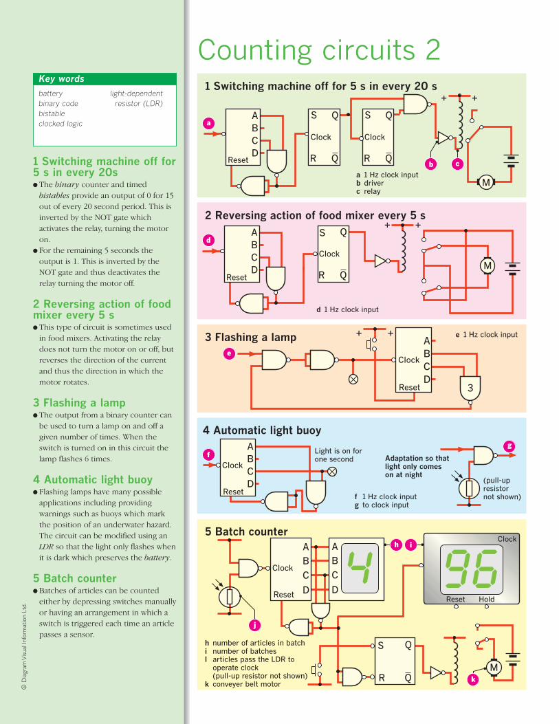
1 Switching machine off for5 s in every 20s● The binary counter and timed
bistables provide an output of 0 for 15out of every 20 second period. This isinverted by the NOT gate whichactivates the relay, turning the motoron.
● For the remaining 5 seconds theoutput is 1. This is inverted by theNOT gate and thus deactivates therelay turning the motor off.
2 Reversing action of food mixer every 5 s● This type of circuit is sometimes used
in food mixers. Activating the relaydoes not turn the motor on or off, butreverses the direction of the currentand thus the direction in which themotor rotates.
3 Flashing a lamp● The output from a binary counter can
be used to turn a lamp on and off agiven number of times. When theswitch is turned on in this circuit thelamp flashes 6 times.
4 Automatic light buoy● Flashing lamps have many possible
applications including providingwarnings such as buoys which markthe position of an underwater hazard.The circuit can be modified using anLDR so that the light only flashes whenit is dark which preserves the battery.
5 Batch counter● Batches of articles can be counted
either by depressing switches manuallyor having an arrangement in which aswitch is triggered each time an articlepasses a sensor.
batterybinary codebistableclocked logic
light-dependentresistor (LDR)
Key words
1HZLight is on forone second Adaptation so that
light only comeson at night
(pull-upresistornot shown)
+ +
+ +
+ +
5 Batch counter
S Q
1 Switching machine off for 5 s in every 20 s
Reset Hold
Clock
ABCD
2 Reversing action of food mixer every 5 s
ABCD M
M
Reset
Reset
ABCD
Clock
Reset
ABCD
Reset
Clock
AB
C
D
AB
C
DReset
M
a
d
g
e
f
3
Clock
f 1 Hz clock inputg to clock input
Q
S
R
Q
Clock
Q
S
R
Q
Clock
Q
S
R
Q
Clock
a 1 Hz clock inputb driverc relay
h number of articles in batchi number of batchesl articles pass the LDR to
operate clock(pull-up resistor not shown)
k conveyer belt motor
3 Flashing a lamp
d 1 Hz clock input
e 1 Hz clock input
4 Automatic light buoy
Q
S
R
Q
cb
h
j
k
i
*04 Electronics (160-187).qxd 2/2/07 12:24 pm Page 178