Digimatic Indicators - teraskonttori.fi · Digimatic Indicators Digital indicators with Absolute...
12
ABSOLUTE type Digimatic Indicator is complete. Digimatic Indicators Digital indicators with Absolute encoders CATALOG No. E4190-543, 575 Small Tool Instruments and Data Management
Transcript of Digimatic Indicators - teraskonttori.fi · Digimatic Indicators Digital indicators with Absolute...
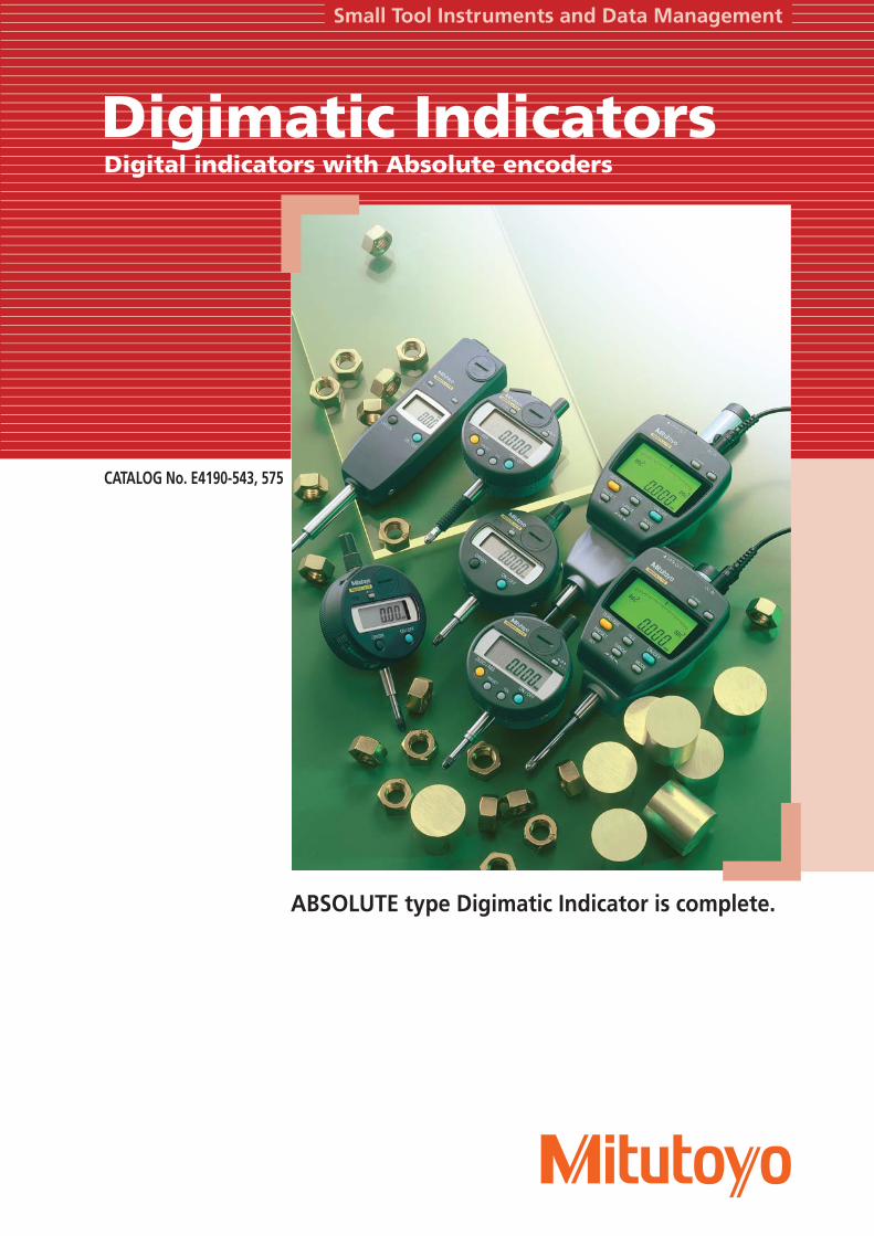
ABSOLUTE type Digimatic Indicator is complete.
Digimatic IndicatorsDigital indicators with Absolute encoders
CATALOG No. E4190-543, 575
Small Tool Instruments and Data Management
2
Mitutoyo Digimatic Indicators
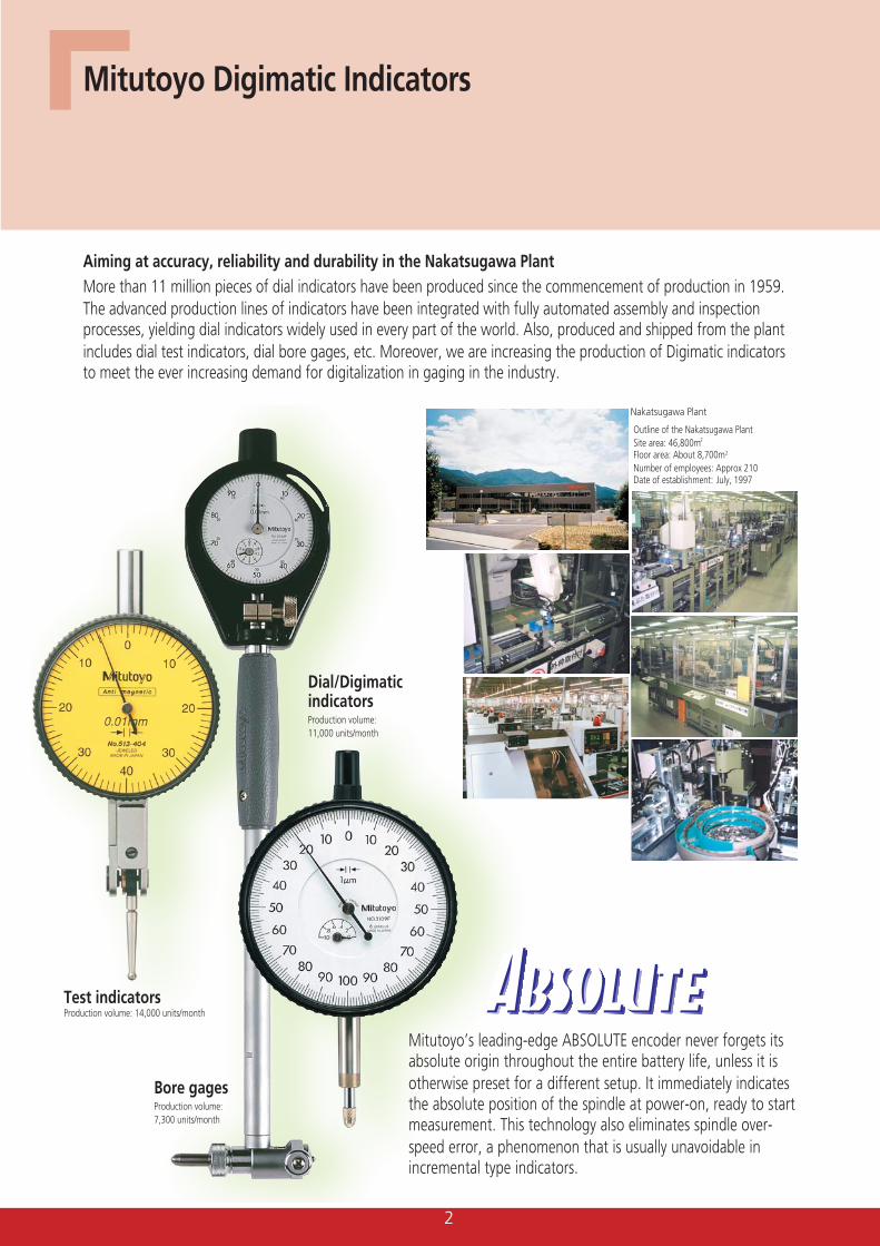
Aiming at accuracy, reliability and durability in the Nakatsugawa PlantMore than 11 million pieces of dial indicators have been produced since the commencement of production in 1959.The advanced production lines of indicators have been integrated with fully automated assembly and inspectionprocesses, yielding dial indicators widely used in every part of the world. Also, produced and shipped from the plantincludes dial test indicators, dial bore gages, etc. Moreover, we are increasing the production of Digimatic indicatorsto meet the ever increasing demand for digitalization in gaging in the industry.
Test indicatorsProduction volume: 14,000 units/month
Bore gagesProduction volume:7,300 units/month
Outline of the Nakatsugawa PlantSite area: 46,800m2
Floor area: About 8,700m2
Number of employees: Approx 210Date of establishment: July, 1997
Mitutoyo’s leading-edge ABSOLUTE encoder never forgets itsabsolute origin throughout the entire battery life, unless it isotherwise preset for a different setup. It immediately indicatesthe absolute position of the spindle at power-on, ready to startmeasurement. This technology also eliminates spindle over-speed error, a phenomenon that is usually unavoidable inincremental type indicators.
Dial/DigimaticindicatorsProduction volume:11,000 units/month
Nakatsugawa Plant
3
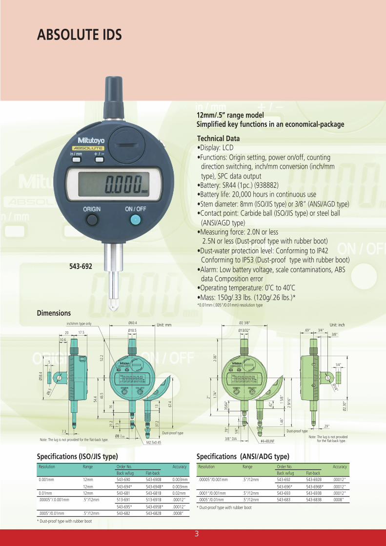
12mm/.5” range modelSimplified key functions in an economical-package
Technical Data•Display: LCD•Functions: Origin setting, power on/off, counting
direction switching, inch/mm conversion (inch/mmtype), SPC data output
•Battery: SR44 (1pc.) (938882)•Battery life: 20,000 hours in continuous use•Stem diameter: 8mm (ISO/JIS type) or 3/8” (ANSI/AGD type)•Contact point: Carbide ball (ISO/JIS type) or steel ball
(ANSI/AGD type)•Measuring force: 2.0N or less
2.5N or less (Dust-proof type with rubber boot)•Dust-water protection level: Conforming to IP42
Conforming to IP53 (Dust-proof type with rubber boot)•Alarm: Low battery voltage, scale contaminations, ABS
data Composition error•Operating temperature: 0˚C to 40˚C•Mass: 150g/.33 lbs. (120g/.26 lbs.)**0.01mm (.005”/0.01mm) resolution type
543-692
Specifications (ISO/JIS type)Resolution Range Order No. Accuracy
Back w/lug Flat-back0.001mm 12mm 543-690 543-690B 0.003mm
12mm 543-694* 543-694B* 0.003mm0.01mm 12mm 543-681 543-681B 0.02mm.00005”/.0.001mm .5”/12mm 513-691 513-691B .00012”
543-695* 543-695B* .00012”.0005”/0.01mm .5”/12mm 543-682 543-682B .0008”
* Dust-proof type with rubber boot
ABSOLUTE IDS
Dimensions
Dust-proof type
20
10.6
Ø58.
4
Ø60.4
Ø10.5
54.4 46
.5
1621
.2
13 67.4
37.2
7.3
52.2
Ø6.5
5
17.5
7.3
Note: The lug is not provided for the flat-back type.Note: The lug is not provided
for the flat-back type.M2.5x0.45
Unit: mm
Ø8 0-0.009
Dust-proof type
Ø2.3
0"
Ø2 3/8"
Ø13/32"
2.06
"
2"
1/4"
1.74
"
.79"
1.46
"
2 9/
16"
1 5/
8"
.42"
35/6
4"
Ø1/4"
.69" 3/4"3/8"
3/8" DIA#4-48UNF
.29"
1/4"
Unit: inchinch/mm type only
Specifications (ANSI/ADG type)Resolution Range Order No. Accuracy
Back w/lug Flat-back.00005”/0.001mm .5”/12mm 543-692 543-692B .00012”
543-696* 543-696B* .00012”.0001”/0.001mm .5”/12mm 543-693 543-693B .00012”.0005”/0.01mm .5”/12mm 543-683 543-683B .0008”
* Dust-proof type with rubber boot
4
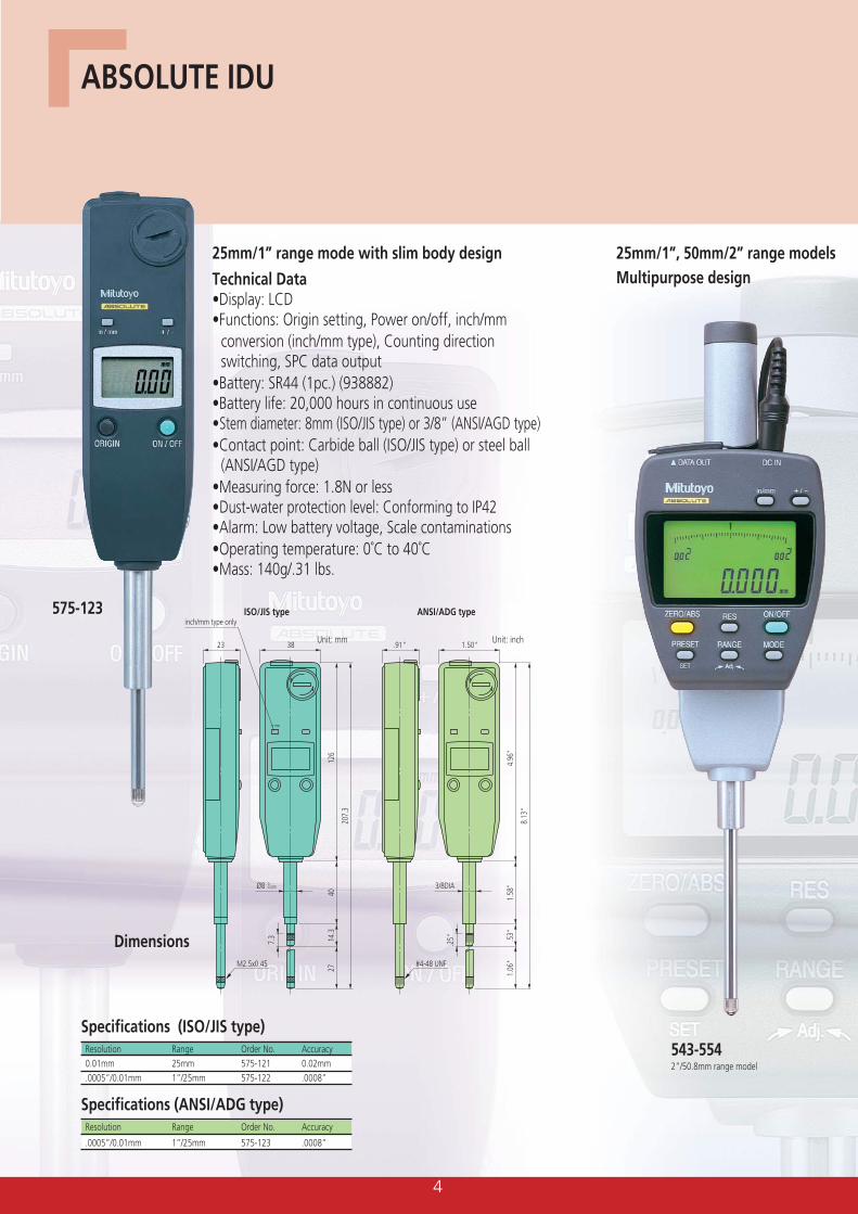
Technical Data•Display: LCD•Functions: Origin setting, Power on/off, inch/mm
conversion (inch/mm type), Counting directionswitching, SPC data output
•Battery: SR44 (1pc.) (938882)•Battery life: 20,000 hours in continuous use•Stem diameter: 8mm (ISO/JIS type) or 3/8” (ANSI/AGD type)•Contact point: Carbide ball (ISO/JIS type) or steel ball
(ANSI/AGD type)•Measuring force: 1.8N or less•Dust-water protection level: Conforming to IP42•Alarm: Low battery voltage, Scale contaminations•Operating temperature: 0˚C to 40˚C•Mass: 140g/.31 lbs.
575-123
Dimensions
ABSOLUTE IDU
Specifications (ISO/JIS type)Resolution Range Order No. Accuracy0.01mm 25mm 575-121 0.02mm.0005”/0.01mm 1”/25mm 575-122 .0008”
25mm/1”, 50mm/2” range modelsMultipurpose design
25mm/1” range mode with slim body design
Ø8 0-0.009
23 38
7.3
207.
3
126
4014
.327
Unit: mm
M2.5x0.45
3/8DIA
.91" 1.50"
.25"
8.13
"
4.96
"1.
58"
.53"
1.06
"
Unit: inch
#4-48 UNF
inch/mm type only
543-5542”/50.8mm range model
ISO/JIS type ANSI/ADG type
Specifications (ANSI/ADG type)Resolution Range Order No. Accuracy
.0005”/0.01mm 1”/25mm 575-123 .0008”
5
Specifications (ISO/JIS type)Resolution Range Order No.* Accuracy
0.001mm 25mm 543-551 0.003mm50mm 543-553 0.006mm
.00005”/0.001mm 1”/25mm 543-552 .00012”
2”/50mm 543-554 .00024”
DimensionØ19.6 (.77")
inch/mmtype only
66 (2.6")
19.5
11 (.43")43.3 (1.70")
(.68"
)
97.3
(3.7
4")
(4.3
2")
110.
685
.2 (3
.35"
)52
3/8"DIA
#4-48UNF thread
M2.5x0.45thread
Ø8 0-0.009
(2.0
5")
Ø19.6 (.77")
inch/mmtype
inch/mmtype
Unit: mm (inch)
66 (2.6")
19.5
(.68"
)
70
(2.6
7")
(3.3
0")
84.8
56.5
(2.2
2")
83.2
(3.2
8")
83.2
(3.2
8")
26
3/8"DIA
#4-48UNFthread
M2.5x0.45thread
Ø8 0-0.009
(1.0
2")
11 (.43")
43.3 (1.70")
inch/mm type only
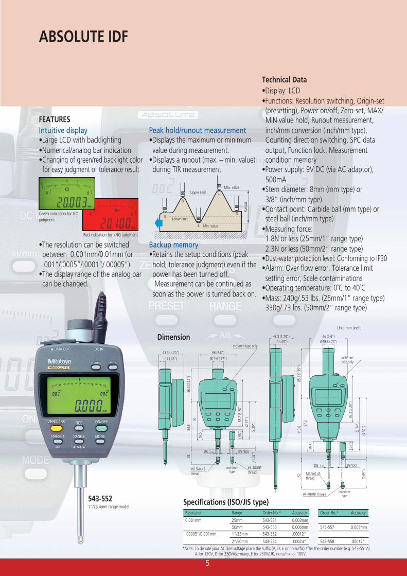
Technical Data•Display: LCD•Functions: Resolution switching, Origin-set(presetting), Power on/off, Zero-set, MAX/MIN value hold, Runout measurement,inch/mm conversion (inch/mm type),Counting direction switching, SPC dataoutput, Function lock, Measurementcondition memory
•Power supply: 9V DC (via AC adaptor),500mA
•Stem diameter: 8mm (mm type) or3/8” (inch/mm type)
•Contact point: Carbide ball (mm type) orsteel ball (inch/mm type)
•Measuring force:1.8N or less (25mm/1” range type)2.3N or less (50mm/2” range type)
•Dust-water protection level: Conforming to IP30•Alarm: Over flow error, Tolerance limitsetting error, Scale contaminations
•Operating temperature: 0˚C to 40˚C•Mass: 240g/.53 lbs. (25mm/1” range type)330g/.73 lbs. (50mm/2” range type)
ABSOLUTE IDF
•The resolution can be switchedbetween 0.001mm/0.01mm (or.001”/.0005”/.0001”/.00005”).
•The display range of the analog barcan be changed.
Green indication for GOjudgment
Red indication for ±NG judgment
543-5521”/25.4mm range model
Peak hold/runout measurement•Displays the maximum or minimumvalue during measurement.
•Displays a runout (max. – min. value)during TIR measurement.
Backup memory•Retains the setup conditions (peakhold, tolerance judgment) even if thepower has been turned off.Measurement can be continued as
soon as the power is turned back on.
Upper limit
Lower limit
Max. value
Min. value
Runo
ut
0
A
B
C
D
*Note: To denote your AC line voltage place the suffix (A, D, E or no suffix) after the order number (e.g. 543-551A)A for 120V, D for 230V/Germany, E for 230V/UK, no suffix for 100V
Order No.* Accuracy
543-557 0.003mm
543-558 .00012”
FEATURESIntuitive display•Large LCD with backlighting•Numerical/analog bar indication•Changing of green/red backlight colorfor easy judgment of tolerance result
6
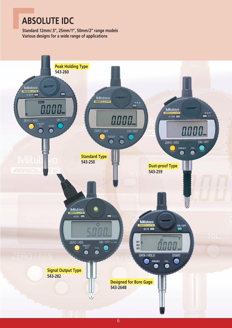
Standard Type543-250
Dust-proof Type543-259
Signal Output Type543-282
Designed for Bore Gage543-264B
ABSOLUTE IDC
Peak Holding Type543-260
Standard 12mm/.5”, 25mm/1”, 50mm/2” range modelsVarious designs for a wide range of applications
7
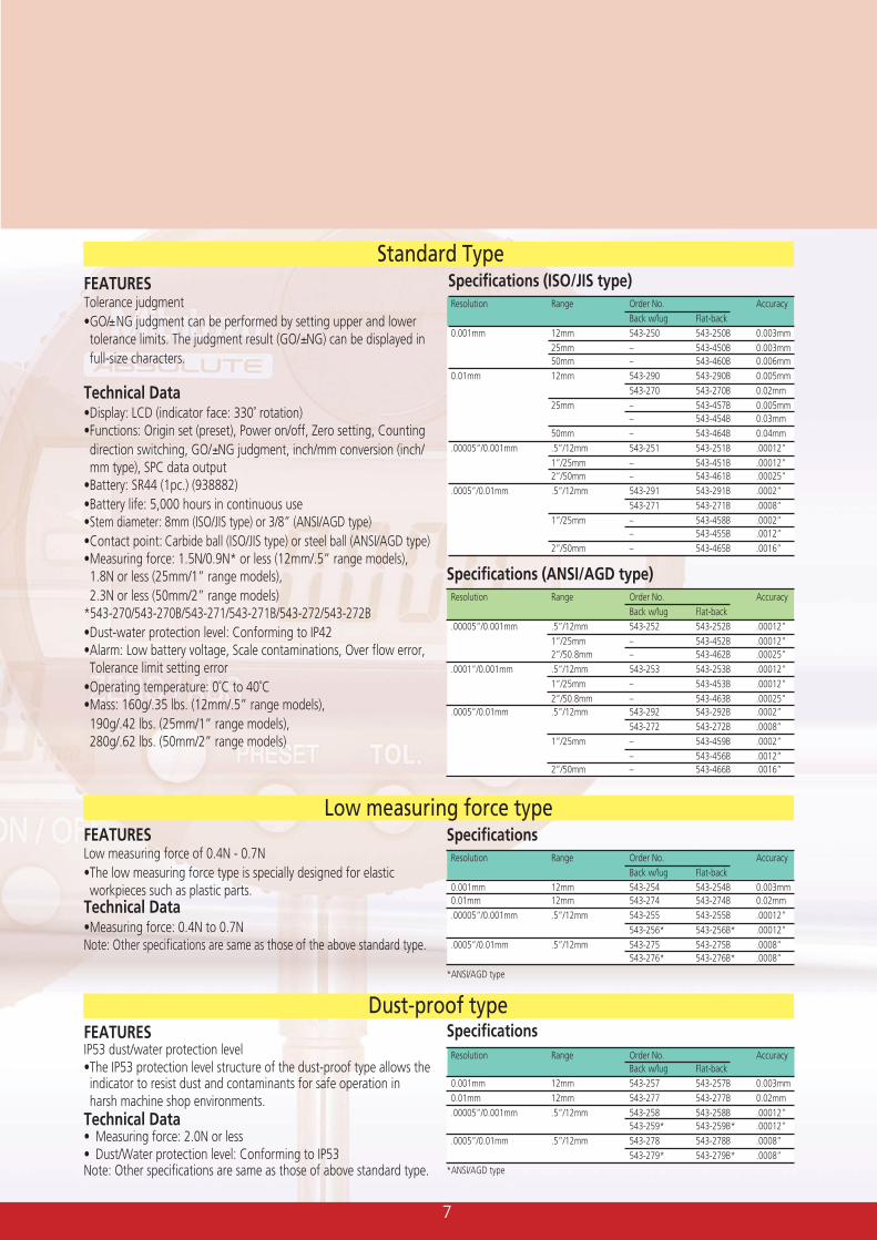
Standard TypeSpecifications (ISO/JIS type)Resolution Range Order No. Accuracy
Back w/lug Flat-back0.001mm 12mm 543-250 543-250B 0.003mm
25mm – 543-450B 0.003mm50mm – 543-460B 0.006mm
0.01mm 12mm 543-290 543-290B 0.005mm543-270 543-270B 0.02mm
25mm – 543-457B 0.005mm– 543-454B 0.03mm
50mm – 543-464B 0.04mm.00005”/0.001mm .5”/12mm 543-251 543-251B .00012”
1”/25mm – 543-451B .00012”2”/50mm – 543-461B .00025”
.0005”/0.01mm .5”/12mm 543-291 543-291B .0002”543-271 543-271B .0008”
1”/25mm – 543-458B .0002”– 543-455B .0012”
2”/50mm – 543-465B .0016”
FEATURESTolerance judgment•GO/±NG judgment can be performed by setting upper and lowertolerance limits. The judgment result (GO/±NG) can be displayed infull-size characters.
Technical Data•Display: LCD (indicator face: 330˚ rotation)•Functions: Origin set (preset), Power on/off, Zero setting, Countingdirection switching, GO/±NG judgment, inch/mm conversion (inch/mm type), SPC data output
•Battery: SR44 (1pc.) (938882)•Battery life: 5,000 hours in continuous use•Stem diameter: 8mm (ISO/JIS type) or 3/8” (ANSI/AGD type)•Contact point: Carbide ball (ISO/JIS type) or steel ball (ANSI/AGD type)•Measuring force: 1.5N/0.9N* or less (12mm/.5” range models),1.8N or less (25mm/1” range models),2.3N or less (50mm/2” range models)
*543-270/543-270B/543-271/543-271B/543-272/543-272B•Dust-water protection level: Conforming to IP42•Alarm: Low battery voltage, Scale contaminations, Over flow error,Tolerance limit setting error
•Operating temperature: 0˚C to 40˚C•Mass: 160g/.35 lbs. (12mm/.5” range models),190g/.42 lbs. (25mm/1” range models),280g/.62 lbs. (50mm/2” range models)
FEATURESIP53 dust/water protection level•The IP53 protection level structure of the dust-proof type allows theindicator to resist dust and contaminants for safe operation inharsh machine shop environments.
Technical Data• Measuring force: 2.0N or less• Dust/Water protection level: Conforming to IP53Note: Other specifications are same as those of above standard type.
Dust-proof type
FEATURESLow measuring force of 0.4N - 0.7N•The low measuring force type is specially designed for elasticworkpieces such as plastic parts.
Technical Data•Measuring force: 0.4N to 0.7NNote: Other specifications are same as those of the above standard type.
Low measuring force type
SpecificationsResolution Range Order No. Accuracy
Back w/lug Flat-back0.001mm 12mm 543-257 543-257B 0.003mm0.01mm 12mm 543-277 543-277B 0.02mm.00005”/0.001mm .5”/12mm 543-258 543-258B .00012”
543-259* 543-259B* .00012”.0005”/0.01mm .5”/12mm 543-278 543-278B .0008”
543-279* 543-279B* .0008”*ANSI/AGD type
Specifications (ANSI/AGD type)Resolution Range Order No. Accuracy
Back w/lug Flat-back.00005”/0.001mm .5”/12mm 543-252 543-252B .00012”
1”/25mm – 543-452B .00012”2”/50.8mm – 543-462B .00025”
.0001”/0.001mm .5”/12mm 543-253 543-253B .00012”1”/25mm – 543-453B .00012”2”/50.8mm – 543-463B .00025”
.0005”/0.01mm .5”/12mm 543-292 543-292B .0002”543-272 543-272B .0008”
1”/25mm – 543-459B .0002”– 543-456B .0012”
2”/50mm – 543-466B .0016”
SpecificationsResolution Range Order No. Accuracy
Back w/lug Flat-back0.001mm 12mm 543-254 543-254B 0.003mm0.01mm 12mm 543-274 543-274B 0.02mm.00005”/0.001mm .5”/12mm 543-255 543-255B .00012”
543-256* 543-256B* .00012”.0005”/0.01mm .5”/12mm 543-275 543-275B .0008”
543-276* 543-276B* .0008”
*ANSI/AGD type
8
ABSOLUTE IDC
Peak Holding Type
Signal Output Type
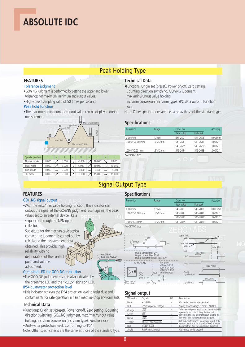
FEATURESTolerance judgment•GO/±NG judgment is performed by setting the upper and lowertolerances for maximum, minimum and runout values.
•High-speed sampling ratio of 50 times per second.Peak hold function•The maximum, minimum, or runout value can be displayed duringmeasurement.
Technical Data•Functions: Origin set (preset), Power on/off, Zero setting,
Counting direction switching, GO/±NG judgment,max./min./runout value holdinginch/mm conversion (inch/mm type), SPC data output, Functionlock
Note: Other specifications are the same as those of the standard type.
FEATURESGO/±NG signal output•With the max./min. value holding function, this indicator can
output the signal of the GO/±NG judgment result against the peakvalues set to an external device like asequencer through the NPN open-collector.Substitute for the mechanical/electricalcontact, the judgment is carried out bycalculating the measurement dataobtained. This provides highreliability with nodeterioration of the contactpoint and volumeadjustment.
Green/red LED for GO/±NG indication•The GO/±NG judgment result is also indicated by
the green/red LED and the “<,O,>” signs on LCD.IP54 dust/water protection level•This indicator achieves the IP54 protection level to resist dust and
contaminants for safe operation in harsh machine shop environments.
20mm
4m, Ø5mm, Core wire AWG/24
Load
Output voltage: Max. 24VOutput current: Max. 30mAOutput saturated voltage: Max. 0.3V
SG
OUT
SG
OUT
1000pF
DC+12-24V Use a non- voltage output such as an open collector output or relay output.
Input current: Max. 10mA
1000pF
24kΩ
Upper limitvalue
Lower limitvalue
OK
-NG
+NG
Max. 40ms
Max. 40ms
Signal outputPower
Max. 700ms
Signal input
Min. 30ms
GO
+NG-NG
Technical Data•Functions: Origin set (preset), Power on/off, Zero setting, Counting
direction switching, GO/±NG judgment, max./min./runout valueholding, inch/mm conversion (inch/mm type), Function lock
•Dust-water protection level: Conforming to IP54Note: Other specifications are the same as those of the standard type.
SpecificationsResolution Range Order No. Accuracy
Back w/lug Flat-back
0.001mm 12mm 543-280 543-280B 0.003mm.00005”/0.001mm .5”/12mm 543-281 543-281B .00012”
543-282* 543-282B* .00012”
.0005”/0.01mm .5”/12mm 543-283* 543-283B* .00012”
*ANSI/AGD type
SpecificationsResolution Range Order No. Accuracy
Back w/lug Flat-back
0.001mm 12mm 543-260 543-260B 0.003mm.00005”/0.001mm .5”/12mm 543-261 543-261B .00012”
543-262* 543-262B* .00012”
.0001”/0.001mm .5”/12mm 543-263* 543-263B* .00012”
*ANSI/AGD type
Upper limit
Lower limit
Max. value (12.000)
9.000
Min. value (-5.000)
Runo
ut
0
A
B
C
D
Spindle position 0 – A – B – C – DNormal mode 0.000 5.000 -5.000 10.000 0.000
Max. mode 0.000 5.000 5.000 10.000 10.000Min. mode 0.000 0.000 -5.000 -5.000 -5.000TIR mode 0.000 5.000 10.000 15.000 15.000
Signal outputWire color Signal I/O Description
Black -V (GND) – Connected to minus (-) terminalRed +V (plus power voltage) I Supply power voltage (12VDC - 24VDC)
Orange -NG OGreen OK O
Brown +NG OYellow PRESET_RECALL/ZERO I
Blue HOLD_RESET IShield FG (Frame Ground) – Connected to the ground.
Tolerance judgment result output terminals (NPNopen-collector output): Only the terminalcorresponding to a judgment result is set to thelow level. (See the output circuit diagram.)External input terminals (no-voltage input): If therelevant terminal is set to the low level, its signalbecomes true. (See the input circuit diagram.)
9
Designed for Bore Gage
M2.5x0.45
Ø8 0-0.009
Ø8 0-0.009
Ø8 0-0.009
M2.5x0.45
Ø6.5
Ø10.520 27.6
10.6
Ø60
.5
Ø54
21.2
16.5
7.6
5
7.3
54.4
49.6
Ø19.638.5
11
Ø60
.5
40.8
19.5
7.3
84.8
56.5
16
M2.5x0.45
ISO/JIS type
Unit: mm
Ø19.638.5
11
Ø60
.5
65.3
19.5
7.3
110.
685
.2
#4-48 UNF
3/8" DIA#4-48 UNF
1/4"
13/32"3/4" 1.09"
3/8"
Ø2
3/8"
2.13
" D
IA
.79"
.9/1
6"
.3"
1/4"
1/4"
2"1.
95"
3/8" DIA
.77"1.52"
.43"
Ø2
3/8"
1.66
"
.68"
.25"
3.30
"2.
22"
#4-48 UNF
3/8" DIA
.77"
1.52"
.43"
Ø2
3/8"
2.62
"
.68"
.25"
4.32
"3.
35"
ANSI/AGD type
Unit: inch
With lug type
2010.6
5
7.6
Ø60
.5
Ø6.
5
4m, Ø5mm, Core wire AWG/24
M2.5x0.45
Ø10.5
49.6
20
67.4 43
.5
37.2
13.5
7.3
Ø54
Ø8 0-0.009Dimensions
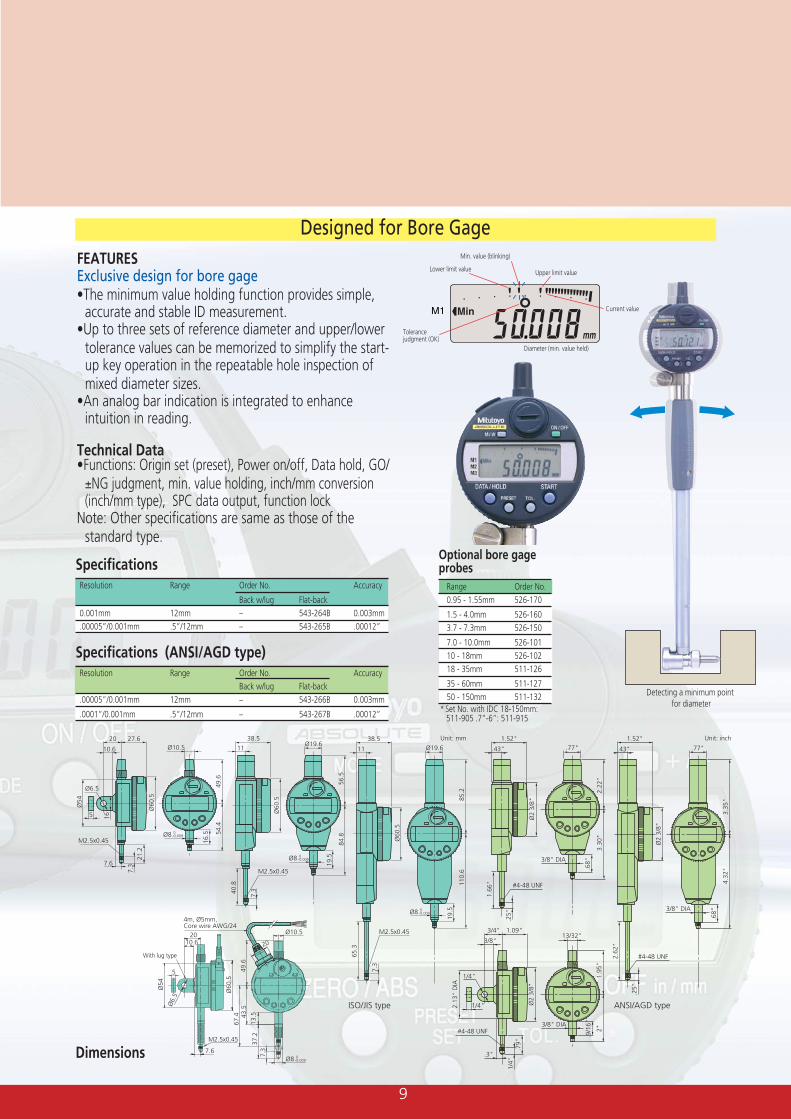
Upper limit value
Current value
Min. value (blinking)
Diameter (min. value held)
Lower limit value
Tolerance judgment (OK)
Detecting a minimum point for diameter
FEATURESExclusive design for bore gage•The minimum value holding function provides simple,
accurate and stable ID measurement.•Up to three sets of reference diameter and upper/lower
tolerance values can be memorized to simplify the start-up key operation in the repeatable hole inspection ofmixed diameter sizes.
•An analog bar indication is integrated to enhanceintuition in reading.
Technical Data•Functions: Origin set (preset), Power on/off, Data hold, GO/±NG judgment, min. value holding, inch/mm conversion(inch/mm type), SPC data output, function lock
Note: Other specifications are same as those of thestandard type.
SpecificationsResolution Range Order No. Accuracy
Back w/lug Flat-back0.001mm 12mm – 543-264B 0.003mm.00005”/0.001mm .5”/12mm – 543-265B .00012”
Optional bore gageprobes
Range Order No.0.95 - 1.55mm 526-170
1.5 - 4.0mm 526-1603.7 - 7.3mm 526-150
7.0 - 10.0mm 526-10110 - 18mm 526-10218 - 35mm 511-126
35 - 60mm 511-12750 - 150mm 511-132
Specifications (ANSI/AGD type)Resolution Range Order No. Accuracy
Back w/lug Flat-back.00005”/0.001mm 12mm – 543-266B 0.003mm
.0001”/0.001mm .5”/12mm – 543-267B .00012” * Set No. with IDC 18-150mm: 511-905 .7”-6”: 511-915
10
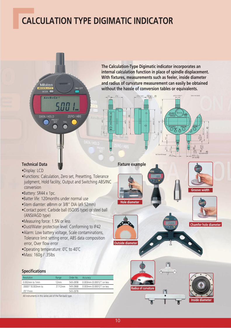
The Calculation-Type Digimatic indicator incorporates aninternal calculation function in place of spindle displacement.With fixtures, measurements such as feeler, inside diameterand radius of curvature measurement can easily be obtainedwithout the hassle of conversion tables or equivalents.
27.6 (1.09")27.6 7.6 (.30")7.6
ø60.
5 (2
3/8
")
ø60.
5
ø54
(2.1
3")
ø54
44.2
(17.
4")
50.9
5 (2
.00"
)
20.0
5(.7
9")
6.35
(1/4
")
14.2
(9/1
6")
M2.5x0.45 thread
49.6
(1.
95")
54.4 46
.5
16.5
21.2
7.3
ø8 0– 0.03
0– 0.009
No.4-48 thread
Unit: mm (inch)
ø9.52
3/8"DIA
ø10.5 (13/32")
CALCULATION TYPE DIGIMATIC INDICATOR
Technical Data•Display: LCD•Functions: Calculation, Zero set, Presetting, Tolerance
judgment, Hold facility, Output and Switching ABS/INCconversion
•Battery: SR44 x 1pc.•Batter life: 120months under normal use•Stem diamter: ø8mm or 3/8” DIA (ø9.52mm)•Contact point: Carbide ball (ISO/JIS type) or steel ball
(ANSI/AGD type)•Measuring force: 1.5N or less•Dust/Water protection level: Conforming to IP42•Alarm: Low battery voltage, Scale contaminations,
Tolerance limit setting error, ABS data compositionerror, Over flow error
•Operating temperature: 0˚C to 40˚C•Mass: 160g / .35lbs
SpecificationsResolution Range Order No. Accuracy
0.002mm to 1mm 12mm 543-285B 0.003mm (0.00012") or less
.00001”/0.003mm to .5”/12mm 543-286B 0.003mm (0.00012") or less
.05”/1mm 543-287B
All instruments in this series are of the flat-back type.
Fixture example
Outside diameter
Inside diameter
Groove width
Hole diameter
Chamfer hole diameter
Radius of curvature
11
D
x
D
x
D
d
xHx
rR
x
2L
RxR
r
2L
r
Contact point free
Fixture
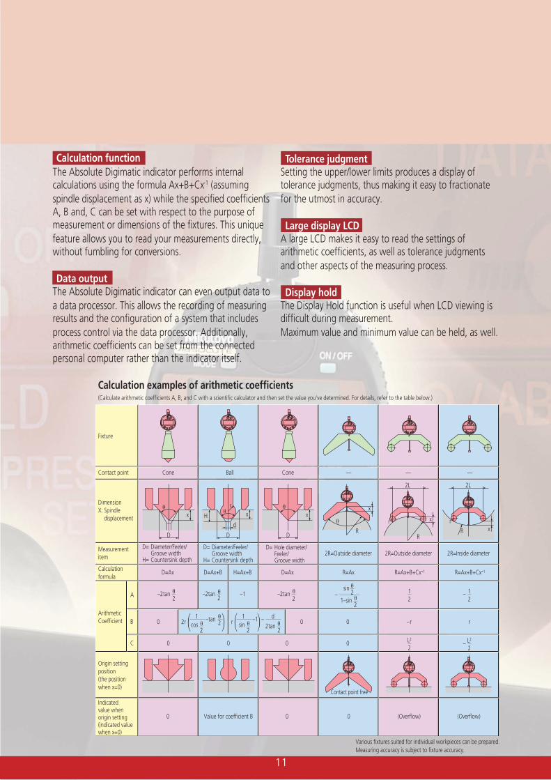
Contact point Cone Ball Cone — — —
Measurementitem
DimensionX: Spindle displacement
D= Diameter/Feeler/ Groove width H= Countersink depth
D= Diameter/Feeler/ Groove width H= Countersink depth
D= Hole diameter/ Feeler/ Groove width
2R=Outside diameter 2R=Outside diameter 2R=Inside diameter
Calculationformula
D=Ax D=Ax+B H=Ax+B D=Ax R=Ax R=Ax+B+Cx-1 R=Ax+B+Cx-1
Arithmetic Coefficient
A
B
C
–tancos
1
220 00
0 0 0 0
Origin settingposition(the positionwhen x=0)
Indicated value when origin setting(indicated value when x=0)
0 Value for coefficient B 0 0 (Overflow) (Overflow)
r–r–1sin
1
2
– 2tan
d
2
–2tan2
–2tan –12
–2tan2 1–sin
–
2
sin2– 1
212
–L2
2L2
2
2r r
Calculation functionThe Absolute Digimatic indicator performs internalcalculations using the formula Ax+B+Cx-1 (assumingspindle displacement as x) while the specified coefficientsA, B and, C can be set with respect to the purpose ofmeasurement or dimensions of the fixtures. This uniquefeature allows you to read your measurements directly,without fumbling for conversions.
Data outputThe Absolute Digimatic indicator can even output data toa data processor. This allows the recording of measuringresults and the configuration of a system that includesprocess control via the data processor. Additionally,arithmetic coefficients can be set from the connectedpersonal computer rather than the indicator itself.
Various fixtures suited for individual workpieces can be prepared.Measuring accuracy is subject to fixture accuracy.
Calculation examples of arithmetic coefficients(Calculate arithmetic coefficients A, B, and C with a scientific calculator and then set the value you've determined. For details, refer to the table below.)
Tolerance judgmentSetting the upper/lower limits produces a display oftolerance judgments, thus making it easy to fractionatefor the utmost in accuracy.
Large display LCDA large LCD makes it easy to read the settings ofarithmetic coefficients, as well as tolerance judgmentsand other aspects of the measuring process.
Display holdThe Display Hold function is useful when LCD viewing isdifficult during measurement.Maximum value and minimum value can be held, as well.
Mitutoyo Scandinavia ABSläntv. 6 • Box 712SE-194 27 Upplands VäsbyTel: 08-594 109 50Fax: 08-590 924 [email protected]
Note:All our product details, in particular the illustrations, drawings,dimension and performance details and other technicalspecifications contained in this publication are to be consideredto be approximate average values. To this extent, we reservethe right to make changes in design, technical data, dimensionsand weight. Our specified standards, similar technical rulesand technical specifications, descriptions and illustrations of theproducts are correct at the time of printing. The current versionof our general terms and conditions also apply. Only offers whichwe have submitted can be considered to be definitive.
81.0
0040
8 (1
) AeF
P , Pr
inte
d in
Japa
n