Digidesign Plug-Ins Guideakmedia.digidesign.com/.../docs/Digidesign_Plug-Ins... · Maxim Controls...
175
Digidesign Plug-Ins Version 7.0 ®
Transcript of Digidesign Plug-Ins Guideakmedia.digidesign.com/.../docs/Digidesign_Plug-Ins... · Maxim Controls...
Digidesign Plug-Ins
Version 7.0
®
Copyright
© 2005 Digidesign, a division of Avid Technology, Inc. All rights reserved. This guide may not be duplicated in whole or in part without the express written consent of Digidesign.
Digidesign, Avid, and Pro Tools are either trademarks or registered trademarks of Avid Technology, Inc. in the US and other countries. All other trademarks contained herein are the property of their respective owners.
Product features, specifications, system requirements, and availability are subject to change without notice.
PN 9329-17739-00 REV A 10/05
contents
Chapter 1. Introduction . . . . . . . . . . . . . . . . . . . . . . . . . . . . . . . . . . . . . . . . . . . . . . . . . . . . . . 1
Plug-In Formats. . . . . . . . . . . . . . . . . . . . . . . . . . . . . . . . . . . . . . . . . . . . . . . . . . . . . . . . . . 1
System Requirements . . . . . . . . . . . . . . . . . . . . . . . . . . . . . . . . . . . . . . . . . . . . . . . . . . . . . 2
Digidesign Registration . . . . . . . . . . . . . . . . . . . . . . . . . . . . . . . . . . . . . . . . . . . . . . . . . . . . 2
Conventions Used in This Guide . . . . . . . . . . . . . . . . . . . . . . . . . . . . . . . . . . . . . . . . . . . . . . 3
About www.digidesign.com . . . . . . . . . . . . . . . . . . . . . . . . . . . . . . . . . . . . . . . . . . . . . . . . . 3
Chapter 2. Installation . . . . . . . . . . . . . . . . . . . . . . . . . . . . . . . . . . . . . . . . . . . . . . . . . . . . . . . 5
Authorizing Plug-Ins. . . . . . . . . . . . . . . . . . . . . . . . . . . . . . . . . . . . . . . . . . . . . . . . . . . . . . . 6
Removing Expired Plug-Ins . . . . . . . . . . . . . . . . . . . . . . . . . . . . . . . . . . . . . . . . . . . . . . . . . . 7
Chapter 3. Working with Real-Time Plug-Ins . . . . . . . . . . . . . . . . . . . . . . . . . . . . . . . . . . . . 9
Processing Power Requirements of TDM and RTAS Plug-Ins . . . . . . . . . . . . . . . . . . . . . . . . . . 9
Delay in Signal Processing . . . . . . . . . . . . . . . . . . . . . . . . . . . . . . . . . . . . . . . . . . . . . . . . . 12
Plug-Ins as Inserts . . . . . . . . . . . . . . . . . . . . . . . . . . . . . . . . . . . . . . . . . . . . . . . . . . . . . . . 13
Organizing Plug-Ins . . . . . . . . . . . . . . . . . . . . . . . . . . . . . . . . . . . . . . . . . . . . . . . . . . . . . . 15
Inserting Plug-Ins on Tracks . . . . . . . . . . . . . . . . . . . . . . . . . . . . . . . . . . . . . . . . . . . . . . . . 16
Clip Indicators. . . . . . . . . . . . . . . . . . . . . . . . . . . . . . . . . . . . . . . . . . . . . . . . . . . . . . . . . . 18
The Plug-In Window. . . . . . . . . . . . . . . . . . . . . . . . . . . . . . . . . . . . . . . . . . . . . . . . . . . . . . 19
Adjusting Plug-In Parameters . . . . . . . . . . . . . . . . . . . . . . . . . . . . . . . . . . . . . . . . . . . . . . . 22
Using the Side-Chain Input . . . . . . . . . . . . . . . . . . . . . . . . . . . . . . . . . . . . . . . . . . . . . . . . . 23
Tempo Sync . . . . . . . . . . . . . . . . . . . . . . . . . . . . . . . . . . . . . . . . . . . . . . . . . . . . . . . . . . . 24
Automating Plug-Ins . . . . . . . . . . . . . . . . . . . . . . . . . . . . . . . . . . . . . . . . . . . . . . . . . . . . . 25
Using the Librarian . . . . . . . . . . . . . . . . . . . . . . . . . . . . . . . . . . . . . . . . . . . . . . . . . . . . . . 27
Plug-In Settings Dialog. . . . . . . . . . . . . . . . . . . . . . . . . . . . . . . . . . . . . . . . . . . . . . . . . . . . 30
Multiple Outputs for Instrument Plug-Ins . . . . . . . . . . . . . . . . . . . . . . . . . . . . . . . . . . . . . . . 31
HTDM Plug-In Conversion to RTAS. . . . . . . . . . . . . . . . . . . . . . . . . . . . . . . . . . . . . . . . . . . . 32
RTAS Plug-Ins on Auxiliary Input and Master Fader Tracks. . . . . . . . . . . . . . . . . . . . . . . . . . . 32
Contents iii
iv
Chapter 4. Working with AudioSuite Plug-Ins . . . . . . . . . . . . . . . . . . . . . . . . . . . . . . . . . 35
The AudioSuite Menu . . . . . . . . . . . . . . . . . . . . . . . . . . . . . . . . . . . . . . . . . . . . . . . . . . . . 35
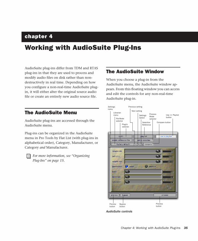
The AudioSuite Window . . . . . . . . . . . . . . . . . . . . . . . . . . . . . . . . . . . . . . . . . . . . . . . . . . 35
AudioSuite Processing Preferences . . . . . . . . . . . . . . . . . . . . . . . . . . . . . . . . . . . . . . . . . . 41
Using AudioSuite Plug-Ins . . . . . . . . . . . . . . . . . . . . . . . . . . . . . . . . . . . . . . . . . . . . . . . . . 42
Chapter 5. D-Fi . . . . . . . . . . . . . . . . . . . . . . . . . . . . . . . . . . . . . . . . . . . . . . . . . . . . . . . . . . . . . 45
Lo-Fi . . . . . . . . . . . . . . . . . . . . . . . . . . . . . . . . . . . . . . . . . . . . . . . . . . . . . . . . . . . . . . . . 46
Sci-Fi. . . . . . . . . . . . . . . . . . . . . . . . . . . . . . . . . . . . . . . . . . . . . . . . . . . . . . . . . . . . . . . . 48
Recti-Fi . . . . . . . . . . . . . . . . . . . . . . . . . . . . . . . . . . . . . . . . . . . . . . . . . . . . . . . . . . . . . . 50
Vari-Fi . . . . . . . . . . . . . . . . . . . . . . . . . . . . . . . . . . . . . . . . . . . . . . . . . . . . . . . . . . . . . . . 52
D-Fi Demo Session . . . . . . . . . . . . . . . . . . . . . . . . . . . . . . . . . . . . . . . . . . . . . . . . . . . . . . 52
Chapter 6. DINR . . . . . . . . . . . . . . . . . . . . . . . . . . . . . . . . . . . . . . . . . . . . . . . . . . . . . . . . . . . 57
Broadband Noise Reduction . . . . . . . . . . . . . . . . . . . . . . . . . . . . . . . . . . . . . . . . . . . . . . . 57
Broadband Noise Reduction Controls . . . . . . . . . . . . . . . . . . . . . . . . . . . . . . . . . . . . . . . . . 59
Using Broadband Noise Reduction . . . . . . . . . . . . . . . . . . . . . . . . . . . . . . . . . . . . . . . . . . . 63
Using BNR AudioSuite. . . . . . . . . . . . . . . . . . . . . . . . . . . . . . . . . . . . . . . . . . . . . . . . . . . . 67
Chapter 7. Maxim . . . . . . . . . . . . . . . . . . . . . . . . . . . . . . . . . . . . . . . . . . . . . . . . . . . . . . . . . . 69
About Peak Limiting . . . . . . . . . . . . . . . . . . . . . . . . . . . . . . . . . . . . . . . . . . . . . . . . . . . . . 70
Maxim Controls and Meters. . . . . . . . . . . . . . . . . . . . . . . . . . . . . . . . . . . . . . . . . . . . . . . . 71
Using Maxim . . . . . . . . . . . . . . . . . . . . . . . . . . . . . . . . . . . . . . . . . . . . . . . . . . . . . . . . . . 74
Chapter 8. Bruno and Reso. . . . . . . . . . . . . . . . . . . . . . . . . . . . . . . . . . . . . . . . . . . . . . . . . . 75
DSP Requirements . . . . . . . . . . . . . . . . . . . . . . . . . . . . . . . . . . . . . . . . . . . . . . . . . . . . . . 76
Inserting Bruno/Reso onto an Audio Track . . . . . . . . . . . . . . . . . . . . . . . . . . . . . . . . . . . . . 76
Playing Bruno/Reso . . . . . . . . . . . . . . . . . . . . . . . . . . . . . . . . . . . . . . . . . . . . . . . . . . . . . 77
Using an External Key Input for Side-Chain Processing . . . . . . . . . . . . . . . . . . . . . . . . . . . . . 78
Bruno Controls . . . . . . . . . . . . . . . . . . . . . . . . . . . . . . . . . . . . . . . . . . . . . . . . . . . . . . . . . 79
Reso Controls . . . . . . . . . . . . . . . . . . . . . . . . . . . . . . . . . . . . . . . . . . . . . . . . . . . . . . . . . 84
Chapter 9. Reverb One. . . . . . . . . . . . . . . . . . . . . . . . . . . . . . . . . . . . . . . . . . . . . . . . . . . . . . 93
A Reverb Overview . . . . . . . . . . . . . . . . . . . . . . . . . . . . . . . . . . . . . . . . . . . . . . . . . . . . . . 93
Reverb One Controls . . . . . . . . . . . . . . . . . . . . . . . . . . . . . . . . . . . . . . . . . . . . . . . . . . . . . 94
Digidesign Plug-Ins Guide
Chapter 10. SoundReplacer . . . . . . . . . . . . . . . . . . . . . . . . . . . . . . . . . . . . . . . . . . . . . . . . 103
Audio Replacement Techniques . . . . . . . . . . . . . . . . . . . . . . . . . . . . . . . . . . . . . . . . . . . . 103
SoundReplacer Controls. . . . . . . . . . . . . . . . . . . . . . . . . . . . . . . . . . . . . . . . . . . . . . . . . . 104
Using SoundReplacer. . . . . . . . . . . . . . . . . . . . . . . . . . . . . . . . . . . . . . . . . . . . . . . . . . . . 107
Getting Optimum Results with SoundReplacer . . . . . . . . . . . . . . . . . . . . . . . . . . . . . . . . . . 108
Using the Audio Files Folder for Frequently Used Replacement Files. . . . . . . . . . . . . . . . . . . 110
Chapter 11. SurroundScope . . . . . . . . . . . . . . . . . . . . . . . . . . . . . . . . . . . . . . . . . . . . . . . . 113
Using SurroundScope. . . . . . . . . . . . . . . . . . . . . . . . . . . . . . . . . . . . . . . . . . . . . . . . . . . . 113
SurroundScope Displays . . . . . . . . . . . . . . . . . . . . . . . . . . . . . . . . . . . . . . . . . . . . . . . . . 114
Chapter 12. Impact . . . . . . . . . . . . . . . . . . . . . . . . . . . . . . . . . . . . . . . . . . . . . . . . . . . . . . . . 117
Impact Parameters . . . . . . . . . . . . . . . . . . . . . . . . . . . . . . . . . . . . . . . . . . . . . . . . . . . . . 117
Impact Parameters . . . . . . . . . . . . . . . . . . . . . . . . . . . . . . . . . . . . . . . . . . . . . . . . . . . . . 118
Using a Key Input for External Side-Chain Processing . . . . . . . . . . . . . . . . . . . . . . . . . . . . . 121
Chapter 13. ReVibe . . . . . . . . . . . . . . . . . . . . . . . . . . . . . . . . . . . . . . . . . . . . . . . . . . . . . . . . 123
Reverberation Concepts . . . . . . . . . . . . . . . . . . . . . . . . . . . . . . . . . . . . . . . . . . . . . . . . . . 124
Using ReVibe . . . . . . . . . . . . . . . . . . . . . . . . . . . . . . . . . . . . . . . . . . . . . . . . . . . . . . . . . 125
Adjusting ReVibe Parameters . . . . . . . . . . . . . . . . . . . . . . . . . . . . . . . . . . . . . . . . . . . . . . 126
ReVibe Controls . . . . . . . . . . . . . . . . . . . . . . . . . . . . . . . . . . . . . . . . . . . . . . . . . . . . . . . 127
ReVibe Room Types . . . . . . . . . . . . . . . . . . . . . . . . . . . . . . . . . . . . . . . . . . . . . . . . . . . . 138
Chapter 14. Smack! . . . . . . . . . . . . . . . . . . . . . . . . . . . . . . . . . . . . . . . . . . . . . . . . . . . . . . . 143
Using Smack! . . . . . . . . . . . . . . . . . . . . . . . . . . . . . . . . . . . . . . . . . . . . . . . . . . . . . . . . . 144
Smack! Parameters. . . . . . . . . . . . . . . . . . . . . . . . . . . . . . . . . . . . . . . . . . . . . . . . . . . . . 144
Using the Side-Chain Input in Smack! . . . . . . . . . . . . . . . . . . . . . . . . . . . . . . . . . . . . . . . . 149
Appendix A. DSP Requirements for TDM Plug-Ins . . . . . . . . . . . . . . . . . . . . . . . . . . . . . 151
DSP Requirements . . . . . . . . . . . . . . . . . . . . . . . . . . . . . . . . . . . . . . . . . . . . . . . . . . . . . 152
Appendix B. DSP Delays Incurred by TDM Plug-Ins . . . . . . . . . . . . . . . . . . . . . . . . . . . . 157
Index . . . . . . . . . . . . . . . . . . . . . . . . . . . . . . . . . . . . . . . . . . . . . . . . . . . . . . . . . . . . . . . . . . . . 159
Contents v

vi
Digidesign Plug-Ins Guide
chapter 1
Introduction
Digidesign plug-ins provide a comprehensive set of digital signal processing tools for profes-sional audio production.
This guide explains the use of each of the plug-ins currently available from Digidesign.
These plug-ins include:
• D-Fi™ creative sound design plug-ins
• DINR™ intelligent noise reduction
• Maxim™ peak limiter/sound maximizer
• Bruno™ & Reso™ cross-synthesis plug-ins
• Reverb One™
• SoundReplacer™ drum and sound replace-ment plug-in
• SurroundScope™
• Impact™
• ReVibe™
• Smack!
For more information on using plug-ins during mixdown with Pro Tools, see the Pro Tools Reference Guide.
Plug-In FormatsPlug-ins are special-purpose software compo-nents that provide additional signal processing functionality to Pro Tools. There are three for-mats of plug-ins:
• TDM plug-ins (real-time, DSP-based)
• RTAS plug-ins (real-time, host-based)
• AudioSuite plug-ins (non-real-time, file-based processing)
TDM Plug-Ins(Pro Tools|HD Systems Only)
TDM (Time Division Multiplexing) plug-ins function as track inserts, are applied to audio during playback, and process audio non-destructively in real time. TDM plug-ins are de-signed for use on Pro Tools|HD systems, and rely on the processing power of Digidesign DSP cards.
Chapter 1: Introduction 1
2
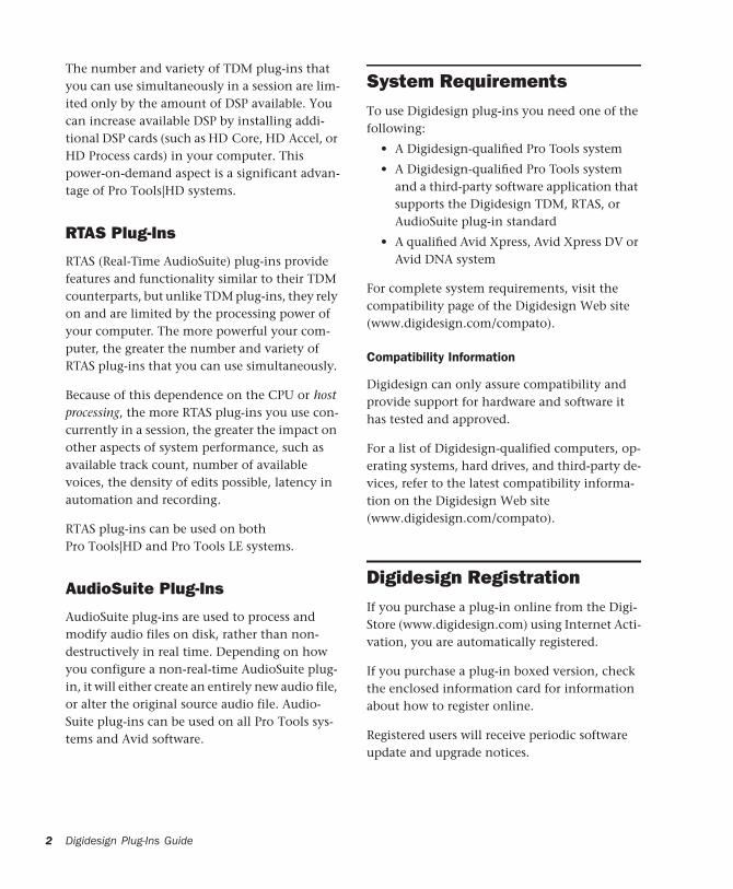
The number and variety of TDM plug-ins that you can use simultaneously in a session are lim-ited only by the amount of DSP available. You can increase available DSP by installing addi-tional DSP cards (such as HD Core, HD Accel, or HD Process cards) in your computer. This power-on-demand aspect is a significant advan-tage of Pro Tools|HD systems.
RTAS Plug-Ins
RTAS (Real-Time AudioSuite) plug-ins provide features and functionality similar to their TDM counterparts, but unlike TDM plug-ins, they rely on and are limited by the processing power of your computer. The more powerful your com-puter, the greater the number and variety of RTAS plug-ins that you can use simultaneously.
Because of this dependence on the CPU or host processing, the more RTAS plug-ins you use con-currently in a session, the greater the impact on other aspects of system performance, such as available track count, number of available voices, the density of edits possible, latency in automation and recording.
RTAS plug-ins can be used on both Pro Tools|HD and Pro Tools LE systems.
AudioSuite Plug-Ins
AudioSuite plug-ins are used to process and modify audio files on disk, rather than non-destructively in real time. Depending on how you configure a non-real-time AudioSuite plug-in, it will either create an entirely new audio file, or alter the original source audio file. Audio-Suite plug-ins can be used on all Pro Tools sys-tems and Avid software.
Digidesign Plug-Ins Guide
System RequirementsTo use Digidesign plug-ins you need one of the following:
• A Digidesign-qualified Pro Tools system
• A Digidesign-qualified Pro Tools system and a third-party software application that supports the Digidesign TDM, RTAS, or AudioSuite plug-in standard
• A qualified Avid Xpress, Avid Xpress DV or Avid DNA system
For complete system requirements, visit the compatibility page of the Digidesign Web site (www.digidesign.com/compato).
Compatibility Information
Digidesign can only assure compatibility and provide support for hardware and software it has tested and approved.
For a list of Digidesign-qualified computers, op-erating systems, hard drives, and third-party de-vices, refer to the latest compatibility informa-tion on the Digidesign Web site (www.digidesign.com/compato).
Digidesign RegistrationIf you purchase a plug-in online from the Digi-Store (www.digidesign.com) using Internet Acti-vation, you are automatically registered.
If you purchase a plug-in boxed version, check the enclosed information card for information about how to register online.
Registered users will receive periodic software update and upgrade notices.
Please refer to the Digidesign Web site (www.digidesign.com) or the registration card for information on technical support.
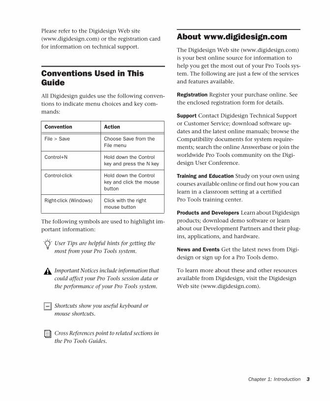
Conventions Used in This GuideAll Digidesign guides use the following conven-tions to indicate menu choices and key com-mands::
The following symbols are used to highlight im-portant information:
Convention Action
File > Save Choose Save from the File menu
Control+N Hold down the Control key and press the N key
Control-click Hold down the Control key and click the mouse button
Right-click (Windows) Click with the right mouse button
User Tips are helpful hints for getting the most from your Pro Tools system.
Important Notices include information that could affect your Pro Tools session data or the performance of your Pro Tools system.
Shortcuts show you useful keyboard or mouse shortcuts.
Cross References point to related sections in the Pro Tools Guides.
About www.digidesign.comThe Digidesign Web site (www.digidesign.com) is your best online source for information to help you get the most out of your Pro Tools sys-tem. The following are just a few of the services and features available.
Registration Register your purchase online. See the enclosed registration form for details.
Support Contact Digidesign Technical Support or Customer Service; download software up-dates and the latest online manuals; browse the Compatibility documents for system require-ments; search the online Answerbase or join the worldwide Pro Tools community on the Digi-design User Conference.
Training and Education Study on your own using courses available online or find out how you can learn in a classroom setting at a certified Pro Tools training center.
Products and Developers Learn about Digidesign products; download demo software or learn about our Development Partners and their plug-ins, applications, and hardware.
News and Events Get the latest news from Digi-design or sign up for a Pro Tools demo.
To learn more about these and other resources available from Digidesign, visit the Digidesign Web site (www.digidesign.com).
Chapter 1: Introduction 3

4
Digidesign Plug-Ins Guide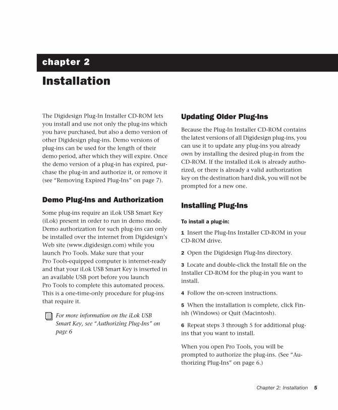
chapter 2
Installation
The Digidesign Plug-In Installer CD-ROM lets you install and use not only the plug-ins which you have purchased, but also a demo version of other Digidesign plug-ins. Demo versions of plug-ins can be used for the length of their demo period, after which they will expire. Once the demo version of a plug-in has expired, pur-chase the plug-in and authorize it, or remove it (see “Removing Expired Plug-Ins” on page 7).
Demo Plug-Ins and Authorization
Some plug-ins require an iLok USB Smart Key (iLok) present in order to run in demo mode. Demo authorization for such plug-ins can only be installed over the internet from Digidesign’s Web site (www.digidesign.com) while you launch Pro Tools. Make sure that your Pro Tools-equipped computer is internet-ready and that your iLok USB Smart Key is inserted in an available USB port before you launch Pro Tools to complete this automated process. This is a one-time-only procedure for plug-ins that require it.
For more information on the iLok USB Smart Key, see “Authorizing Plug-Ins” on page 6
Updating Older Plug-Ins
Because the Plug-In Installer CD-ROM contains the latest versions of all Digidesign plug-ins, you can use it to update any plug-ins you already own by installing the desired plug-in from the CD-ROM. If the installed iLok is already autho-rized, or there is already a valid authorization key on the destination hard disk, you will not be prompted for a new one.
Installing Plug-Ins
To install a plug-in:
1 Insert the Plug-Ins Installer CD-ROM in your CD-ROM drive.
2 Open the Digidesign Plug-Ins directory.
3 Locate and double-click the Install file on the Installer CD-ROM for the plug-in you want to install.
4 Follow the on-screen instructions.
5 When the installation is complete, click Fin-ish (Windows) or Quit (Macintosh).
6 Repeat steps 3 through 5 for additional plug-ins that you want to install.
When you open Pro Tools, you will be prompted to authorize the plug-ins. (See “Au-thorizing Plug-Ins” on page 6.)
Chapter 2: Installation 5
6
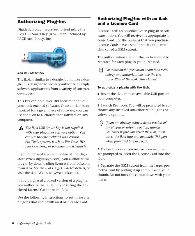
Authorizing Plug-InsDigidesign plug-ins are authorized using the iLok USB Smart Key (iLok), manufactured by PACE Anti-Piracy, Inc.
The iLok is similar to a dongle, but unlike a don-gle, it is designed to securely authorize multiple software applications from a variety of software developers.
This key can hold over 100 licenses for all of your iLok-enabled software. Once an iLok is au-thorized for a given piece of software, you can use the iLok to authorize that software on any computer.
If you purchased a plug-in online at the Digi-Store (www.digidesign.com), you authorize the plug-in by downloading licenses from iLok.com to an iLok. See the iLok Usage Guide for details, or visit the iLok Web site (www.iLok.com).
If you purchased a boxed version of a plug-in, you authorize the plug-in by inserting the en-closed License Card into an iLok.
Use the following instructions to authorize any plug-ins that come with an iLok License Card.
iLok USB Smart Key
The iLok USB Smart Key is not supplied with your plug-in or software option. You can use the one included with certain Pro Tools systems (such as Pro Tools|HD-series systems), or purchase one separately.
Digidesign Plug-Ins Guide
Authorizing Plug-Ins with an iLok and a License Card
License Cards are specific to each plug-in or soft-ware option. You will receive the appropriate Li-cense Cards for the plug-ins that you purchase. License Cards have a small punch-out plastic chip called a GSM cutout.
The authorization steps in this section must be repeated for each plug-in you purchased.
To authorize a plug-in with the iLok:
1 Insert the iLok into an available USB port on your computer.
2 Launch Pro Tools. You will be prompted to au-thorize any installed unauthorized plug-ins or software options.
3 Follow the on-screen instructions until you are prompted to insert the License Card into the iLok.
4 Separate the GSM cutout from the larger pro-tective card by pulling it up and out with your thumb. Do not force the cutout down with your finger.
For additional information about iLok tech-nology and authorizations, see the elec-tronic PDF of the iLok Usage Guide.
If you are already using a demo version of the plug-in or software option, launch Pro Tools before you insert the iLok, then insert the iLok into any available USB port when prompted by Pro Tools.

5 Insert the GSM cutout into the iLok. Visually verify that the metal portion of the cutout makes contact with the iLok’s metal card reader.
6 Follow the on-screen instructions to complete the authorization process for each plug-in.
7 After the authorization has completed, re-move the GSM cutout from the iLok. (If you have to remove the iLok from the computer to remove the cutout, be sure to re-insert the iLok in any available USB port on your computer when you are finished.)
Removing Expired Plug-InsIf you let a demo version of a plug-in or software option expire, you should remove it from your system. Otherwise, each time you open Pro Tools you will be prompted with a message that the plug-in has expired.
To remove an expired plug-in on Windows XP:
1 Click Start.
2 Click Control Panel.
3 Double-click Add or Remove Programs.
4 Select the expired plug-in or software option from the list of installed applications.
5 Click the Change/Remove button.
6 Click OK to remove the option.
iLok with License Card
7 When removal is complete, close the Add or Remove Programs window.
To remove an expired plug-in:
1 Open the Plug-Ins folder on your Startup drive (Library/Application Support/Digidesign).
2 Drag the expired plug-in to the Trash.
3 Empty the Trash.
Chapter 2: Installation 7

8
Digidesign Plug-Ins Guide
chapter 3
Working with Real-Time Plug-Ins
Real-time plug-ins process audio nondestruc-tively in real time. They do not alter the original source audio, but only apply their effect during playback.
There are two formats of real-time plug-ins:
TDM Plug-Ins Rely on the processing power of Digidesign DSP cards. TDM plug-ins run only on Pro Tools|HD systems.
RTAS Plug-Ins Rely on the processing power of your computer. RTAS plug-ins run on Pro Tools|HD and LE systems.
Processing Power Requirements of TDM and RTAS Plug-InsTDM and RTAS plug-ins differ in their process-ing power requirements.
TDM Plug-Ins
Each real-time TDM plug-in that is inserted in a Pro Tools session uses a portion of your system’s total available DSP resources.
Since these DSP resources reside on the cards that make up your particular Pro Tools hard-ware configuration, the amount of DSP avail-able depends entirely on the number and type of DSP cards in your system.
You can add more mixing and processing power to your system by installing additional DSP cards, provided you have unused PCI expansion slots in your computer or use a Digidesign-ap-proved Expansion Chassis.
Chapter 3: Working with Real-Time Plug-Ins 9
10
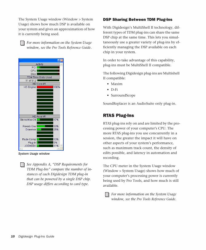
The System Usage window (Window > System Usage) shows how much DSP is available on your system and gives an approximation of how it is currently being used.
For more information on the System Usage window, see the Pro Tools Reference Guide.
System Usage window
See Appendix A, “DSP Requirements for TDM Plug-Ins” compare the number of in-stances of each Digidesign TDM plug-in that can be powered by a single DSP chip. DSP usage differs according to card type.
Digidesign Plug-Ins Guide
DSP Sharing Between TDM Plug-Ins
With Digidesign’s MultiShell II technology, dif-ferent types of TDM plug-ins can share the same DSP chip at the same time. This lets you simul-taneously use a greater variety of plug-ins by ef-ficiently managing the DSP available on each chip in your system.
In order to take advantage of this capability, plug-ins must be MultiShell II compatible.
The following Digidesign plug-ins are Multishell II compatible:
• Maxim
• D-Fi
• SurroundScope
SoundReplacer is an AudioSuite only plug-in.
RTAS Plug-Ins
RTAS plug-ins rely on and are limited by the pro-cessing power of your computer’s CPU. The more RTAS plug-ins you use concurrently in a session, the greater the impact it will have on other aspects of your system’s performance, such as maximum track count, the density of edits possible, and latency in automation and recording.
The CPU meter in the System Usage window (Window > System Usage) shows how much of your computer’s processing power is currently being used by Pro Tools, and how much is still available.
For more information on the System Usage window, see the Pro Tools Reference Guide.
Improving RTAS Plug-In Performance
You can increase the number of RTAS plug-ins your system can use concurrently by increasing the Hardware Buffer Size and CPU Usage Limit.
Hardware Buffer Size
The Hardware Buffer Size (H/W Buffer Size) con-trols the size of the hardware cache used to han-dle host processing tasks such as monitoring la-tency and using Real-Time AudioSuite (RTAS) plug-ins.
◆ Lower Hardware Buffer Size settings reduce monitoring latency, and are useful when you are recording live input.
◆ Higher Hardware Buffer Size settings allow for more audio processing and effects, and are use-ful when you are mixing and using more RTAS plug-ins.
To change the Hardware Buffer Size:
1 Choose Setup > Playback Engine.
2 From the H/W Buffer Size pop-up menu, select the audio buffer size, in samples.
3 Click OK.
In addition to causing slower screen re-sponse and monitoring latency, higher Hardware Buffer Size settings can affect the accuracy of plug-in automation, mute data, and timing for Instrument or MIDI tracks.
CPU Usage Limit
The CPU Usage Limit controls the percentage of CPU resources allocated to Pro Tools host pro-cessing tasks such as RTAS plug-in performance and screen redraws.
◆ Lower CPU Usage Limit settings limit the ef-fect of Pro Tools processing on other CPU-inten-sive tasks, such as screen redraws, and are useful when you are experiencing slow system re-sponse, or when running other applications at the same time as Pro Tools.
◆ Higher CPU Usage Limit settings allocate more processing power to Pro Tools, and are useful for playing back large sessions or using more real-time plug-ins.
To change the CPU Usage Limit:
1 Choose Setup > Playback Engine.
2 From the CPU Usage Limit pop-up menu, se-lect the percentage of CPU processing you want to allocate to Pro Tools. (On dual-processor Mac-intosh computers, this setting controls the allo-cation of a single processor.)
3 Click OK.
RTAS Plug-Ins on Auxiliary Inputs or Master Faders
On Pro Tools|HD systems, RTAS plug-ins can be inserted either on Auxiliary Input or Master Fader tracks or after a TDM plug-in on any kind of track. This can affect voice usage, HTDM con-version, latency, and limitations on inserting or removing plug-ins during playback.
Increasing the CPU Usage Limit may slow down screen response on slower computers.
For more information on Hardware Buffer Size and CPU Usage Limit, see the Pro Tools Reference Guide.
Chapter 3: Working with Real-Time Plug-Ins 11
12
For detailed information, see “RTAS Plug-Ins on Auxiliary Input and Master Fader Tracks” on page 32.
Delay in Signal ProcessingDSP and host-based processing in digital audio systems incurs signal delay of varying amounts. Such delays can vary from as short as few sam-ples to as long as several hundred samples, de-pending on the type of processing applied.
If you have recorded an instrument on multiple tracks using multiple microphones (a drum kit for example) and process the different tracks with different plug-ins, the tracks may go out of phase. You will then need to compensate for these delays to avoid phase cancellation prob-lems.
Compensating for Delay
Use the following methods, as available, to com-pensate for processing delay.
Delay Compensation
Use Delay Compensation to automatically cal-culate and compensate for processing delay. For more information on Delay Compensation, see the Pro Tools Reference Guide.
See Appendix B, “DSP Delays Incurred by TDM Plug-Ins” for information on delays inherent in specific DigiRack TDM plug-ins. See the Pro Tools Reference Guide for a guide to calculating DSP-induced delays.
Delay Compensation is automatically en-abled on Pro Tools LE systems and cannot be turned off.
Digidesign Plug-Ins Guide
TimeAdjuster
You can compensate for TDM plug-in-induced delays by using the TimeAdjuster plug-in. This plug-in lets you apply a specific number of sam-ples of delay to the signal path of a Pro Tools track. TimeAdjuster provides settings files that apply the correct compensation time in samples for delay introduced by one or more plug-ins.
Manual Delay Compensation
You can manually compensate for processing delay by first calculating the amount of delay on each track, and then nudging other track’s play-lists later or earlier in time. This method is useful when Delay Compensation is unavailable, or when you want to conserve resources.
Low-Latency Recording with Instrument Plug-Ins
When an Instrument track containing an in-strument plug-in (or a MIDI track routing MIDI data to an instrument plug-in) is record enabled, Pro Tools automatically suspends delay com-pensation through the main outputs of the au-
For information about TimeAdjuster in Delay Compensation sessions, see the Pro Tools Reference Guide.
You can also compensate for offsets in-curred by processing delays by using the same plug-ins on all tracks.
dio track, Instrument track, or Auxiliary Input on which the instrument plug-in is inserted. This allows for latency-free monitoring of the instru-ment plug-in during recording.
MIDI and Audio Processing Plug-Ins
Some plug-ins, such as Bruno and Reso, process audio while allowing MIDI data to control pro-cessing parameters. When you record enable an Instrument or MIDI track that is controlling an Audio processing plug-in, the track the plug-in is inserted on will go into low-latency mode, ef-fectively making the processed audio play early.
To keep audio time-aligned when using a MIDI controlled plug-in on an audio track:
■ Start-Control-click (Windows) or Command-Control-click (Macintosh) the Track Compensa-tion indicator for the audio track to apply delay compensation.
Delay Compensation for instrument plug-ins works only when all MIDI and audio connections take place inside of Pro Tools. For example, Pro Tools does not suspend delay compensation when you are using Re-Wire to connect software synthesizers and samplers.
To keep audio time-aligned when using a MIDI controlled plug-in on an Auxiliary Input:
1 Start-Control-click (Windows) or Command-Control-click (Macintosh) the Track Compensa-tion indicator for the Auxiliary Input to bypass delay compensation.
2 Enter the total system delay into the User Off-set field.
Plug-Ins as InsertsReal-time plug-ins are available as in-line inserts on audio tracks, Auxiliary Inputs, and Master Faders. A maximum of 5 real-time plug-ins can be used per track.
When more than one insert is used on a track, they process the audio in series, each effect be-ing added to the previous one, from top to bot-tom in the Mix window.
Inserts can be used in two ways:
On Single Tracks An insert can be applied to an individual audio track or Auxiliary Input using the Insert selector on that track.
With in-line inserts, you control the level of ef-fect by adjusting the controls of the plug-in.
As Shared Resources An insert can be used as a shared resource in a send-and-return arrange-ment by bussing signals from several tracks to an Auxiliary Input, and applying the insert to
If you are using both TDM and RTAS plug-ins on the same track, RTAS plug-ins must occur first in the signal chain, followed by TDM plug-ins. You cannot place TDM plug-ins before RTAS plug-ins.
Chapter 3: Working with Real-Time Plug-Ins 13
14
the Auxiliary Input track. With such an arrange-ment, you can control the send level for each track and the overall level of the effect can be controlled from the Auxiliary Input track.
Shared arrangements let you make more effi-cient use of your system’s processing power.
Pre-Fader Operation
Real-time plug-ins function as pre-fader inserts (except on Master Fader tracks, where inserts are post-fader), meaning that their input levels are not affected by a track’s volume fader.
Real-time plug-ins are pre-fader, but post-disk. This means that if you record to disk with a plug-in inserted on the record track, you will hear the effect of the plug-in, but the effect will not be recorded to disk.
To record with a plug-in effect, create an Auxil-iary Input, insert the desired effect on the Aux-iliary Input track, then route the Auxiliary Input to the audio track to which you want to record. Alternatively, bounce the audio track with the plug-in after recording in order to write the ef-fected audio to disk.
Mono, Multi-Mono, and Multichannel Plug-Ins
Plug-ins can be used in mono, multi-mono, or multichannel formats, depending on the type of plug-in and whether the destination is a mono or multichannel track.
AudioSuite plug-ins provide another option for processing audio. See Chapter 4, “Work-ing with AudioSuite Plug-Ins.”
Digidesign Plug-Ins Guide
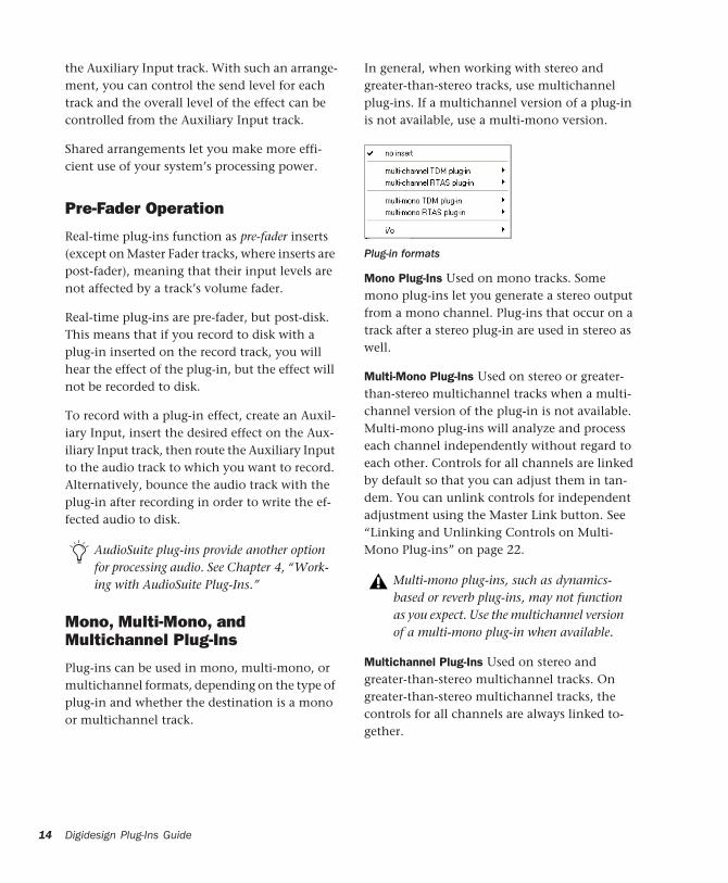
In general, when working with stereo and greater-than-stereo tracks, use multichannel plug-ins. If a multichannel version of a plug-in is not available, use a multi-mono version.
Mono Plug-Ins Used on mono tracks. Some mono plug-ins let you generate a stereo output from a mono channel. Plug-ins that occur on a track after a stereo plug-in are used in stereo as well.
Multi-Mono Plug-Ins Used on stereo or greater-than-stereo multichannel tracks when a multi-channel version of the plug-in is not available. Multi-mono plug-ins will analyze and process each channel independently without regard to each other. Controls for all channels are linked by default so that you can adjust them in tan-dem. You can unlink controls for independent adjustment using the Master Link button. See “Linking and Unlinking Controls on Multi-Mono Plug-ins” on page 22.
Multichannel Plug-Ins Used on stereo and greater-than-stereo multichannel tracks. On greater-than-stereo multichannel tracks, the controls for all channels are always linked to-gether.
Plug-in formats
Multi-mono plug-ins, such as dynamics-based or reverb plug-ins, may not function as you expect. Use the multichannel version of a multi-mono plug-in when available.
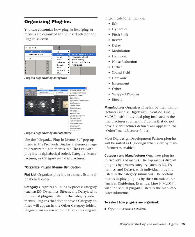
Organizing Plug-InsYou can customize how plug-in lists (plug-in menus) are organized in the Insert selector and Plug-In selector.
Use the “Organize Plug-In Menus By” pop-up menu in the Pro Tools Display Preferences page to organize plug-in menus in a Flat List (with plug-ins in alphabetical order), Category, Manu-facturer, or Category and Manufacturer.
“Organize Plug-In Menus By” Option
Flat List Organizes plug-ins in a single list, in al-phabetical order.
Category Organizes plug-ins by process category (such as EQ, Dynamics, Effects, and Delay), with individual plug-ins listed in the category sub-menus. Plug-Ins that do not have a Category de-fined will appear in the Other Category folder. Plug-ins can appear in more than one category.
Plug-ins organized by categories
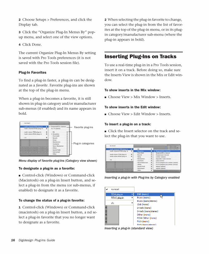
Plug-ins organized by manufacturer
Plug-In categories include:
• EQ
• Dynamics
• Pitch Shift
• Reverb
• Delay
• Modulation
• Harmonic
• Noise Reduction
• Dither
• Sound Field
• Hardware
• Instrument
• Other
• Wrapped Plug-Ins
• Effects
Manufacturer Organizes plug-ins by their manu-facturer (such as Digidesign, Eventide, Line 6, McDSP), with individual plug-ins listed in the manufacturer submenus. Plug-Ins that do not have a Manufacturer defined will appear in the “Other” manufacturer folder.
Most Digidesign Development Partner plug-ins will be sorted as Digidesign when view by man-ufacturer is enabled.
Category and Manufacturer Organizes plug-ins in two levels of menus. The top menus display plug-ins by process category (such as EQ, Dy-namics, and Delay), with individual plug-ins listed in the category submenus. The bottom menus display plug-ins by their manufacturer (such as Digidesign, Eventide, Line 6, McDSP), with individual plug-ins listed in the manufac-turer submenus.
To select how plug-ins are organized:
1 Open or create a session.
Chapter 3: Working with Real-Time Plug-Ins 15
16
2 Choose Setups > Preferences, and click the Display tab.
3 Click the “Organize Plug-In Menus By” pop-up menu, and select one of the view options.
4 Click Done.
The current Organize Plug-In Menus By setting is saved with Pro Tools preferences (it is not saved with the Pro Tools session file).
Plug-In Favorites
To find a plug-in faster, a plug-in can be desig-nated as a favorite. Favorite plug-ins are shown at the top of the plug-in menu.
When a plug-in becomes a favorite, it is still shown in plug-in category and/or manufacturer sub-menus (if enabled) and its name appears in bold.
To designate a plug-in as a favorite:
■ Control-click (Windows) or Command-click (Macintosh) on a plug-in Insert button, and se-lect a plug-in from the menu (or sub-menus, if enabled) to designate it as a favorite.
To change the status of a plug-in favorite:
1 Control-click (Windows) or Command-click (macintosh) on a plug-in Insert button, a nd se-lect a plug-in favorite that you no longer want to designate as a favorite.
Menu display of favorite plug-Ins (Category view shown)
Favorite plug-ins
Plug-in categories
Digidesign Plug-Ins Guide
2 When selecting the plug-in favorite to change, you can select the plug-in from the list of favor-ites at the top of the plug-in menu, or in its plug-in category/manufacturer sub-menu (where the plug-in appears in bold).
Inserting Plug-Ins on TracksTo use a real-time plug-in in a Pro Tools session, insert it on a track. Before doing so, make sure the Inserts View is shown in the Mix or Edit win-dow.
To show inserts in the Mix window:
■ Choose View > Mix Window > Inserts.
To show inserts in the Edit window:
■ Choose View > Edit Window > Inserts.
To insert a plug-in on a track:
■ Click the Insert selector on the track and se-lect the plug-in that you want to use.
Inserting a plug-in with Plug-Ins by Category enabled
Inserting a plug-in (standard view)
click here

Removing an Insert from a Track
To remove an insert from a track:
■ Click the Insert selector and select No Insert.
Configuring Plug-Ins During Playback
On Pro Tools|HD and Pro Tools LE systems, you must stop playback before performing any of the following operations:
◆ Inserting or removing a plug-in while record-ing
◆ Dragging a plug-in to a different location
◆ Inserting or removing a plug-in that changes a track's format
◆ Removing a plug-in that contains automation data
◆ Enabling plug-in controls for automation
◆ Creating an external key side-chain input
◆ Inserting an RTAS plug-in on or removing an RTAS plug-in from an Auxiliary Input or Master Fader track
◆ Inserting an RTAS plug-in after a TDM plug-in on an audio track
◆ Removing an RTAS plug-in from an audio track if it comes after a TDM plug-in
◆ Inserting TDM plug-ins before an RTAS plug-in on an audio track
◆ Removing a TDM plug-in from an audio track if it comes before an RTAS plug-in.
Removing a plug-in
Moving and Duplicating Inserts
You can move or duplicate an insert by dragging it to a different position on the same track or a different track. Inserts that are moved or dupli-cated retain their original settings and automa-tion.
To move an insert:
■ Drag the insert to a new insert location.
To duplicate an insert:
■ Alt-drag (Windows) or Option-drag (Macin-tosh) the insert to a new insert location. The du-plicated plug-in retains its original settings and automation.
Making Plug-Ins Inactive
You can set plug-ins as inactive in order to free up DSP resources for other plug-ins and process-ing. When a plug-in is inactive it retains its as-signment, position, and related automation playlists. However, it will not pass audio and does not consume any DSP or TDM resources.
To toggle a plug-in active or inactive:
■ Control-Start-click (Windows) or Command-Control-click (Macintosh) the Insert button.
– or –
Moving a plug-in
Dragging an insert on top of an existing in-sert will replace it.
Chapter 3: Working with Real-Time Plug-Ins 17
18
Make the track inactive.
To toggle plug-ins in the same insert position (1–5) on all tracks active or inactive:
■ Control-Start-Alt click (Windows) or Com-mand-Control-Option click (Macintosh) an In-sert button in the position you want to toggle.
To toggle plug-ins in the same insert position (1–5) on all selected tracks active or inactive:
■ Control-Start-Alt-Shift-click (Windows) or Command-Control-Option-Shift-click (Macin-tosh) an Insert button in the position you want to toggle.
For more information about making tracks inactive, refer to the Pro Tools Reference Guide.
Digidesign Plug-Ins Guide
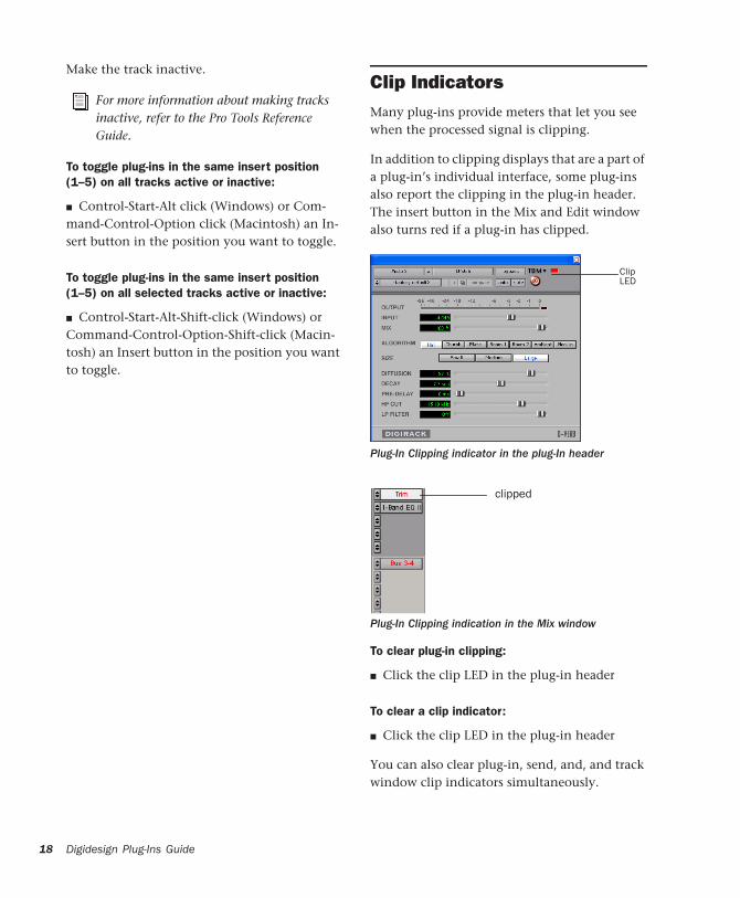
Clip IndicatorsMany plug-ins provide meters that let you see when the processed signal is clipping.
In addition to clipping displays that are a part of a plug-in’s individual interface, some plug-ins also report the clipping in the plug-in header. The insert button in the Mix and Edit window also turns red if a plug-in has clipped.
To clear plug-in clipping:
■ Click the clip LED in the plug-in header
To clear a clip indicator:
■ Click the clip LED in the plug-in header
You can also clear plug-in, send, and, and track window clip indicators simultaneously.
Plug-In Clipping indicator in the plug-In header
Plug-In Clipping indication in the Mix window
ClipLED
clipped
To clear all clip indicators:
■ Alt-click (Windows) or Option-click (Macin-tosh) any meter.
To clear all clip indicators, do one of the following:
■ Alt-click (Windows) or Option-click (Macin-tosh) any meter.
■ Press Alt-C (Windows) or Option-C (Macin-tosh).
■ Choose Track > Clear All Clip Indicators.
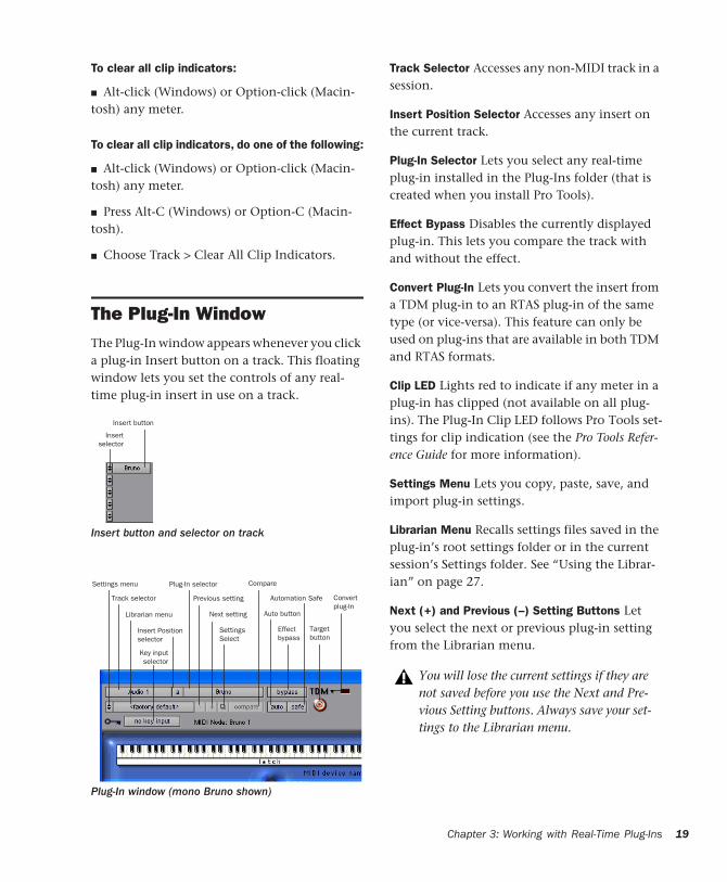
The Plug-In WindowThe Plug-In window appears whenever you click a plug-in Insert button on a track. This floating window lets you set the controls of any real-time plug-in insert in use on a track.
Insert button and selector on track
Plug-In window (mono Bruno shown)
Insertselector
Insert button
Settings menu
Track selector
Librarian menu
Insert Positionselector
Plug-In selector
Previous setting
Next setting
SettingsSelect
Key inputselector
Compare
Targetbutton
Effectbypass
Automation Safe
Auto button
Convertplug-In
Track Selector Accesses any non-MIDI track in a session.
Insert Position Selector Accesses any insert on the current track.
Plug-In Selector Lets you select any real-time plug-in installed in the Plug-Ins folder (that is created when you install Pro Tools).
Effect Bypass Disables the currently displayed plug-in. This lets you compare the track with and without the effect.
Convert Plug-In Lets you convert the insert from a TDM plug-in to an RTAS plug-in of the same type (or vice-versa). This feature can only be used on plug-ins that are available in both TDM and RTAS formats.
Clip LED Lights red to indicate if any meter in a plug-in has clipped (not available on all plug-ins). The Plug-In Clip LED follows Pro Tools set-tings for clip indication (see the Pro Tools Refer-ence Guide for more information).
Settings Menu Lets you copy, paste, save, and import plug-in settings.
Librarian Menu Recalls settings files saved in the plug-in’s root settings folder or in the current session’s Settings folder. See “Using the Librar-ian” on page 27.
Next (+) and Previous (–) Setting Buttons Let you select the next or previous plug-in setting from the Librarian menu.
You will lose the current settings if they are not saved before you use the Next and Pre-vious Setting buttons. Always save your set-tings to the Librarian menu.
Chapter 3: Working with Real-Time Plug-Ins 19
20
Plug-Ins Settings Select Button Accesses the Plug-In Settings dialog, which lists the settings files for the current plug-in. From this list, you can select a new setting, or audition a series of settings.
Compare Toggles between the original saved plug-in setting and any changes you have made to it so you can compare them.
Auto Lets you enable individual plug-in controls for automation recording. See “Automating Plug-Ins” on page 25.
Safe When enabled, prevents existing plug-in automation from being overwritten.
Target Button When multiple Plug-In windows are open, clicking this button selects that plug-in as the target for any computer keyboard com-mands.
Key Input Selector Lets you select audio on a particular input or bus and route it to trigger the plug-in. This menu only appears on plug-ins that feature side-chain processing. Key inputs are monophonic.
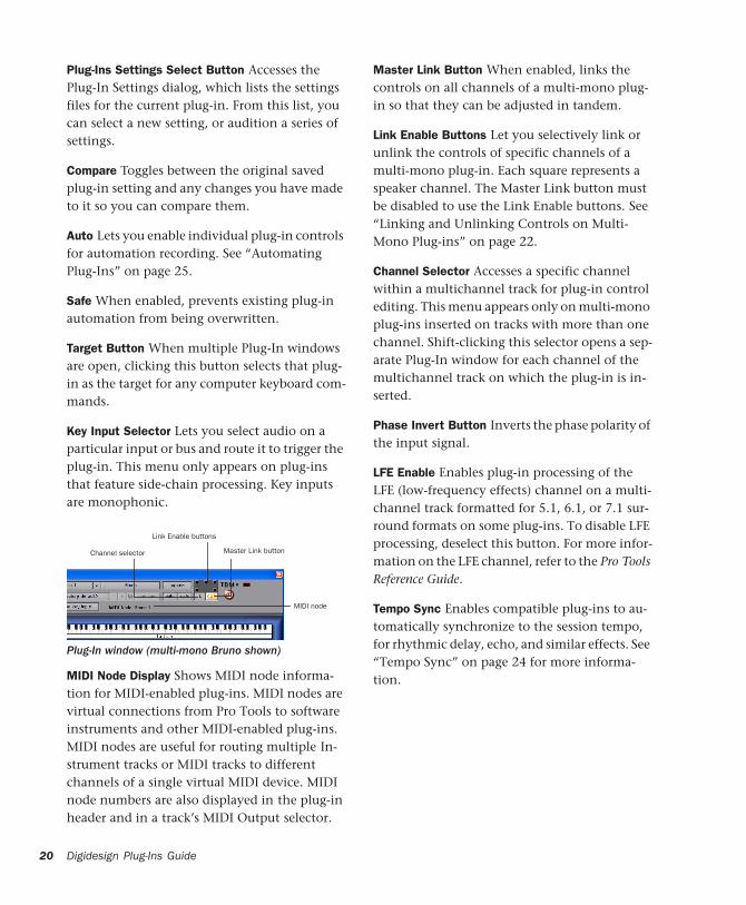
MIDI Node Display Shows MIDI node informa-tion for MIDI-enabled plug-ins. MIDI nodes are virtual connections from Pro Tools to software instruments and other MIDI-enabled plug-ins. MIDI nodes are useful for routing multiple In-strument tracks or MIDI tracks to different channels of a single virtual MIDI device. MIDI node numbers are also displayed in the plug-in header and in a track’s MIDI Output selector.
Plug-In window (multi-mono Bruno shown)
Link Enable buttons
Master Link buttonChannel selector
MIDI node
Digidesign Plug-Ins Guide
Master Link Button When enabled, links the controls on all channels of a multi-mono plug-in so that they can be adjusted in tandem.
Link Enable Buttons Let you selectively link or unlink the controls of specific channels of a multi-mono plug-in. Each square represents a speaker channel. The Master Link button must be disabled to use the Link Enable buttons. See “Linking and Unlinking Controls on Multi-Mono Plug-ins” on page 22.
Channel Selector Accesses a specific channel within a multichannel track for plug-in control editing. This menu appears only on multi-mono plug-ins inserted on tracks with more than one channel. Shift-clicking this selector opens a sep-arate Plug-In window for each channel of the multichannel track on which the plug-in is in-serted.
Phase Invert Button Inverts the phase polarity of the input signal.
LFE Enable Enables plug-in processing of the LFE (low-frequency effects) channel on a multi-channel track formatted for 5.1, 6.1, or 7.1 sur-round formats on some plug-ins. To disable LFE processing, deselect this button. For more infor-mation on the LFE channel, refer to the Pro Tools Reference Guide.
Tempo Sync Enables compatible plug-ins to au-tomatically synchronize to the session tempo, for rhythmic delay, echo, and similar effects. See “Tempo Sync” on page 24 for more informa-tion.
Opening Plug-In Windows
To open a Plug-In window:
■ Click the plug-in button in the Mix or Edit window channel strip.
By default, each plug-in you open will appear in the same location as a currently open plug-in, replacing it in the same window location.
Opening Multiple Plug-In Windows
Pro Tools normally displays a single Plug-In window from which you can adjust the controls of any plug-in in a session. You can also open additional Plug-In windows for specific plug-ins.
Once you begin working with multiple Plug-In windows, you will need to click the Target but-ton on the plug-in whose controls you want to adjust using keyboard commands.
To open an additional Plug-In window:
■ Shift-click the Insert button for the additional plug-in.
To open Plug-In windows for each channel of a multi-mono plug-in:
■ Alt-click (Windows) or Option-click (Macin-tosh) the Channel selector in the Plug-In win-dow of the multi-mono plug-in.
To close all currently open Plug-In windows:
■ Alt-click (Windows) or Option-click (Macin-tosh) the close box of any currently open Plug-In window.
Plug-In Window Controls
All plug-ins provide standard Pro Tools controls for track and insert selection, bypass, and other controls, in addition to processor-specific con-trols.
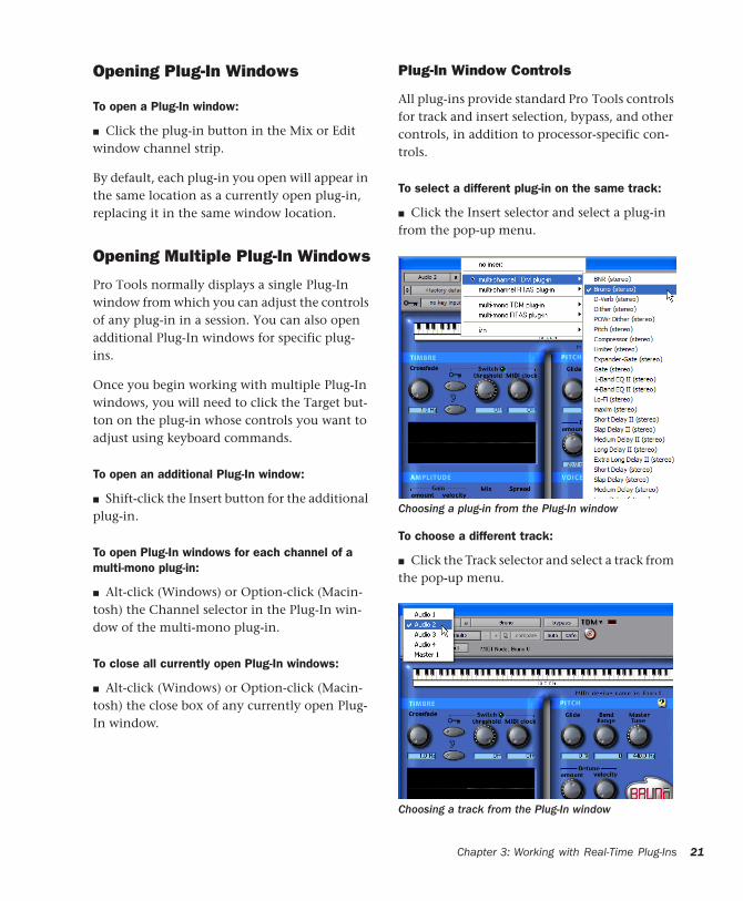
To select a different plug-in on the same track:
■ Click the Insert selector and select a plug-in from the pop-up menu.
To choose a different track:
■ Click the Track selector and select a track from the pop-up menu.
Choosing a plug-in from the Plug-In window
Choosing a track from the Plug-In window
Chapter 3: Working with Real-Time Plug-Ins 21
22
Bypassing Plug-Ins
To bypass a plug-in:
■ Click the Plug-In window’s Bypass button.
– or –
■ Control-click (Windows) or Command-click (Macintosh) the plug-in’s Insert button in the Mix or Edit window.
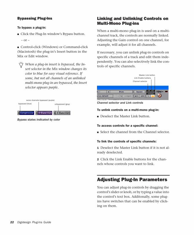
When a plug-in insert is bypassed, the In-sert selector in the Mix window changes its color to blue for easy visual reference. If some, but not all channels of an unlinked multi-mono plug-in are bypassed, the Insert selector appears purple.
Bypass states indicated by color
bypassed (blue)
some channels bypassed (purple)
unbypassed (gray)
Digidesign Plug-Ins Guide
Linking and Unlinking Controls on Multi-Mono Plug-ins
When a multi-mono plug-in is used on a multi-channel track, the controls are normally linked. Adjusting the Gain control on one channel, for example, will adjust it for all channels.
If necessary, you can unlink plug-in controls on specific channels of a track and edit them inde-pendently. You can also selectively link the con-trols of specific channels.
To unlink controls on a multi-mono plug-in:
■ Deselect the Master Link button.
To access controls for a specific channel:
■ Select the channel from the Channel selector.
To link the controls of specific channels:
1 Deselect the Master Link button if it is not al-ready deselected.
2 Click the Link Enable buttons for the chan-nels whose controls you want to link.
Adjusting Plug-In ParametersYou can adjust plug-in controls by dragging the control’s slider or knob, or by typing a value into the control’s text box. Additonally, some plug-ins have switches that can be enabled by click-ing on them.
Channel selector and Link controls
Link Enable buttons
Master Link button
Channel selector
To adjust a plug-in control:
1 Begin audio playback so that you can hear the control changes in real time.
2 Adjust the controls of the plug-in for the effect you want. Refer to “Editing Parameters Using a Mouse” on page 23 and “Editing Parameters Us-ing a Computer Keyboard” on page 23.
3 Closing the plug-in will save the most recent changes.
Editing Parameters Using a Mouse
You can adjust rotary controls by dragging hori-zontally or vertically. Parameter values increase as you drag upward or to the right, and decrease as you drag downward or to the left.
Keyboard Shortcuts
◆ For finer adjustments, Control-drag (Win-dows) or Command-drag (Macintosh) the con-trol.
◆ To return a control to its default value, Alt-click (Windows) or Option-click (Macintosh) the control.
Editing Parameters Using a Computer Keyboard
Some controls have text boxes that display the current value of the parameter. You can edits the numeric value of a parameter with your computer keyboard.
If multiple Plug-In windows are open, Tab and keyboard entry remain focused on the plug-in that is the target window.
To change control values with a computer keyboard:
1 Click on the text box corresponding to the control that you want to adjust.
2 Change the value.
• To increase a value, press the Up Arrow on your keyboard. To decrease a value, press the Down Arrow on your keyboard.
– or –
• Type the desired value.
3 Do one of the following:
• Press Enter on the numeric keyboard to in-put the value and remain in keyboard edit-ing mode.
– or –
• Press Enter on the alpha keyboard (Win-dows) or Return (Macintosh) to enter the value and leave keyboard editing mode.
Enabling Switches
To enable a switch, click on the switch.
Using the Side-Chain InputThe side-chain is the split-off signal used by a plug-in's detector to trigger dynamics process-ing, and is generally drawn internally from the input signal. However, some plug-ins let you switch between internal and external side-chain processing.
With external side-chain processing, a plug-in's detector is triggered by an external signal (such as a separate reference track or audio source) known as the key input.
In fields that support values in kilohertz, typing “k” after a number value will multi-ply the value by 1,000. For example, type “8k” to enter a value of 8,000.
To move forward through the different con-trol fields, press the Tab key. To move back-ward, press Shift+Tab.
Chapter 3: Working with Real-Time Plug-Ins 23

24
A typical use for this feature is to control the dy-namics of one audio signal using the dynamics of another signal (the key input). For example, a kick drum track could be used to trigger gating of a bass track to tighten it up, or a rhythm gui-tar track could be used to gate a keyboard pad.
Side-Chain Filters
Some plug-ins feature key high-pass and low-pass filters. These controls let you define a spe-cific frequency range in the side-chain signal with which to trigger the plug-in effect. A com-mon production technique is to use these con-trols to filter a drum track so that only specific high frequencies (a hi-hat, for example) or low frequencies (a tom or a kick, for example) trigger the effect.
Using a Key Input for External Side-Chain Processing
To use a key input for external side-chain processing:
1 Click the Key Input selector and select the in-put or bus carrying the audio you want to use to trigger the plug-in.
2 Click External Key to activate external side-chain processing.
3 Press the Spacebar to begin playback. The plug-in uses the input or bus that you chose as a key input to trigger its effect.
Choosing a Key Input
Digidesign Plug-Ins Guide
4 During playback, do any of the following to fine-tune side-chain triggering:
• To hear the audio source you have selected to control the side-chain, enable Side-Chain Listen or Key Listen (depending on the plug-in).
• To filter the side-chain so that only specific frequencies trigger the plug-in, use the fil-tering controls (if available) to select the desired frequency range.
5 Adjust the Threshold control (if available) and other controls as needed.
Tempo SyncPro Tools provides Tempo Sync to enhance MIDI Beat Clock support and overall tempo capabili-ties of plug-ins (such as ReWire client applica-tions) that utilize MIDI Beat Clock.
Tempo Sync provides a direct connection be-tween session tempo and plug-in parameters that support MIDI Beat Clock. This direct con-nection lets plug-in parameters such as delay, auto-pan, and other time-domain effects auto-matically synchronize to and follow changes in session tempo.
Tempo Sync simplifies MIDI Beat Clock config-uration by making session tempo available to relevant plug-in parameters directly from within the plug-in window. For plug-ins that do not support Tempo Sync, the original MIDI Beat Clock window (Setup > MIDI > MIDI Beat Clock) remains available in Pro Tools.
Remember to disable Side-Chain Listen/Key Listen to resume normal plug-in monitor-ing.
Compatibility and Settings
When opening older sessions that included plug-ins that subscribe to MIDI Beat Clock, Tempo Sync will be automatically enabled. Any plug-ins that used automation for tempo change should have that automation suspended or deleted to avoid conflict with Tempo Sync.
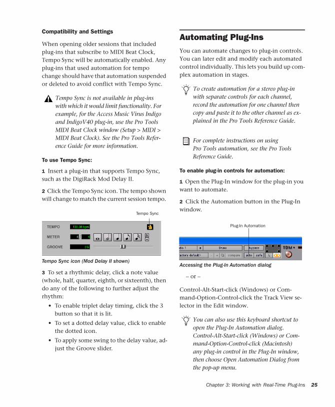
To use Tempo Sync:
1 Insert a plug-in that supports Tempo Sync, such as the DigiRack Mod Delay II.
2 Click the Tempo Sync icon. The tempo shown will change to match the current session tempo.
3 To set a rhythmic delay, click a note value (whole, half, quarter, eighth, or sixteenth), then do any of the following to further adjust the rhythm:
• To enable triplet delay timing, click the 3 button so that it is lit.
• To set a dotted delay value, click to enable the dotted icon.
• To apply some swing to the delay value, ad-just the Groove slider.
Tempo Sync is not available in plug-ins with which it would limit functionality. For example, for the Access Music Virus Indigo and IndigoV40 plug-in, use the Pro Tools MIDI Beat Clock window (Setup > MIDI > MIDI Beat Clock). See the Pro Tools Refer-ence Guide for more information.
Tempo Sync icon (Mod Delay II shown)
Tempo Sync
Automating Plug-InsYou can automate changes to plug-in controls. You can later edit and modify each automated control individually. This lets you build up com-plex automation in stages.
To enable plug-in controls for automation:
1 Open the Plug-In window for the plug-in you want to automate.
2 Click the Automation button in the Plug-In window.
– or –
Control-Alt-Start-click (Windows) or Com-mand-Option-Control-click the Track View se-lector in the Edit window.
To create automation for a stereo plug-in with separate controls for each channel, record the automation for one channel then copy and paste it to the other channel as ex-plained in the Pro Tools Reference Guide.
For complete instructions on using Pro Tools automation, see the Pro Tools Reference Guide.
Accessing the Plug-In Automation dialog
You can also use this keyboard shortcut to open the Plug-In Automation dialog. Control-Alt-Start-click (Windows) or Com-mand-Option-Control-click (Macintosh) any plug-in control in the Plug-In window, then choose Open Automation Dialog from the pop-up menu.
Plug-In Automation
Chapter
3: Working with Real-Time Plug-Ins 25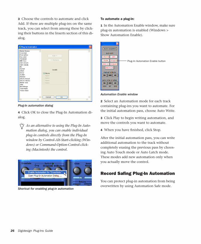
26
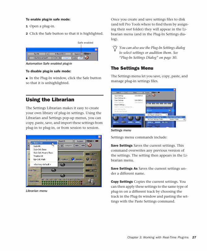
3 Choose the controls to automate and click Add. If there are multiple plug-ins on the same track, you can select from among these by click-ing their buttons in the Inserts section of this di-alog.
4 Click OK to close the Plug-In Automation di-alog.
Plug-In automation dialog
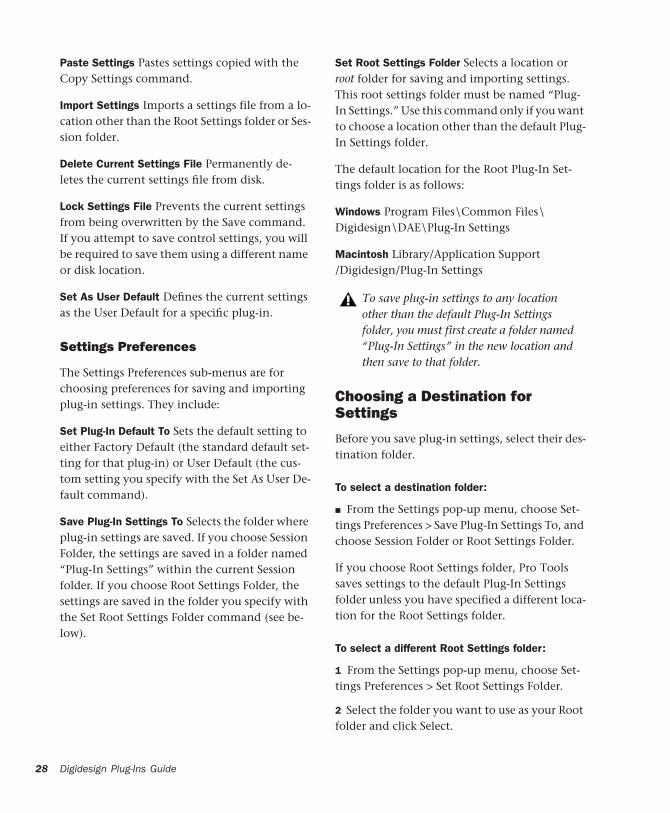
As an alternative to using the Plug-In Auto-mation dialog, you can enable individual plug-in controls directly from the Plug-In window by Control-Alt-Start-clicking (Win-dows) or Command-Option-Control-click-ing (Macintosh) the control.
Shortcut for enabling plug-in automation
Digidesign Plug-Ins Guide
To automate a plug-in:
1 In the Automation Enable window, make sure plug-in automation is enabled (Windows > Show Automation Enable).
2 Select an Automation mode for each track containing plug-ins you want to automate. For the initial automation pass, choose Auto Write.
3 Click Play to begin writing automation, and move the controls you want to automate.
4 When you have finished, click Stop.
After the initial automation pass, you can write additional automation to the track without completely erasing the previous pass by choos-ing Auto Touch mode or Auto Latch mode. These modes add new automation only when you actually move the control.
Record Safing Plug-In Automation
You can protect plug-in automation from being overwritten by using Automation Safe mode.
Automation Enable window
Plug--In Automation Enable button
To enable plug-in safe mode:
1 Open a plug-in.
2 Click the Safe button so that it is highlighted.
To disable plug-in safe mode:
■ In the Plug-In window, click the Safe button so that it is unhighlighted.
Using the LibrarianThe Settings Librarian makes it easy to create your own library of plug-in settings. Using the Librarian and Settings pop-up menus, you can copy, paste, save, and import these settings from plug-in to plug-in, or from session to session.
Automation Safe enabled plug-in
Librarian menu
Safe enabled
Once you create and save settings files to disk (and tell Pro Tools where to find them by assign-ing their root folder) they will appear in the Li-brarian menu (and in the Plug-In Settings dia-log).
The Settings Menu
The Settings menu let you save, copy, paste, and manage plug-in settings files.
Settings menu commands include:
Save Settings Saves the current settings. This command overwrites any previous version of the settings. The setting then appears in the Li-brarian menu.
Save Settings As Saves the current settings un-der a different name.
Copy Settings Copies the current settings. You can then apply these settings to the same type of plug-in on a different track by choosing the track in the Plug-In window and pasting the set-tings with the Paste Settings command.
You can also use the Plug-In Settings dialog to select settings or audition them. See “Plug-In Settings Dialog” on page 30.
Settings menu
Chapter 3: Working with Real-Time Plug-Ins 27
28
Paste Settings Pastes settings copied with the Copy Settings command.
Import Settings Imports a settings file from a lo-cation other than the Root Settings folder or Ses-sion folder.
Delete Current Settings File Permanently de-letes the current settings file from disk.
Lock Settings File Prevents the current settings from being overwritten by the Save command. If you attempt to save control settings, you will be required to save them using a different name or disk location.
Set As User Default Defines the current settings as the User Default for a specific plug-in.
Settings Preferences
The Settings Preferences sub-menus are for choosing preferences for saving and importing plug-in settings. They include:
Set Plug-In Default To Sets the default setting to either Factory Default (the standard default set-ting for that plug-in) or User Default (the cus-tom setting you specify with the Set As User De-fault command).
Save Plug-In Settings To Selects the folder where plug-in settings are saved. If you choose Session Folder, the settings are saved in a folder named “Plug-In Settings” within the current Session folder. If you choose Root Settings Folder, the settings are saved in the folder you specify with the Set Root Settings Folder command (see be-low).
Digidesign Plug-Ins Guide
Set Root Settings Folder Selects a location or root folder for saving and importing settings. This root settings folder must be named “Plug-In Settings.” Use this command only if you want to choose a location other than the default Plug-In Settings folder.
The default location for the Root Plug-In Set-tings folder is as follows:
Windows Program Files\Common Files\Digidesign\DAE\Plug-In Settings
Macintosh Library/Application Support/Digidesign/Plug-In Settings
Choosing a Destination for Settings
Before you save plug-in settings, select their des-tination folder.
To select a destination folder:
■ From the Settings pop-up menu, choose Set-tings Preferences > Save Plug-In Settings To, and choose Session Folder or Root Settings Folder.
If you choose Root Settings folder, Pro Tools saves settings to the default Plug-In Settings folder unless you have specified a different loca-tion for the Root Settings folder.
To select a different Root Settings folder:
1 From the Settings pop-up menu, choose Set-tings Preferences > Set Root Settings Folder.
2 Select the folder you want to use as your Root folder and click Select.
To save plug-in settings to any location other than the default Plug-In Settings folder, you must first create a folder named “Plug-In Settings” in the new location and then save to that folder.
Managing Settings
Use the Settings pop-up menu to manage set-tings.
To save a setting:
1 Choose Save Settings from the Settings pop-up menu.
2 Type a name and click OK. The setting appears in the Librarian menu.
To load a previously saved setting:
■ Choose the setting from the Librarian pop-up menu.
To import a setting:
1 Choose Import Settings from the Settings pop-up menu.
2 Locate the settings file you want to import and click Open. Pro Tools loads the setting and copies it to the root destination folder.
To copy a setting:
■ Choose Copy Settings from the Settings pop-up menu.
To paste a setting:
1 Open the source plug-in.
Unlinked multi-mono plug-ins have specific rules for settings. See “Editing Settings on Unlinked Multi-Mono Plug-ins” on page 30.
Press Control+Shift+S (Windows) or Com-mand+Shift+S (Macintosh) to save plug-in settings.
Press Control+Shift+C (Windows) or Com-mand+Shift+C (Macintosh) to copy plug-in settings.
2 Choose Copy Settings from the Settings pop-up menu.
3 Open the destination plug-in.
4 Choose Paste Settings from the Settings pop-up menu.
To create a custom User Default setting:
1 Create and save a setting.
2 Choose Set As User Default from the Settings pop-up menu.
To make a plug-in default to your custom User Setting:
■ From the Settings pop-up menu, choose Set-tings Preferences > Set Plug-In Default To > User Setting.
Creating Subfolders for Settings
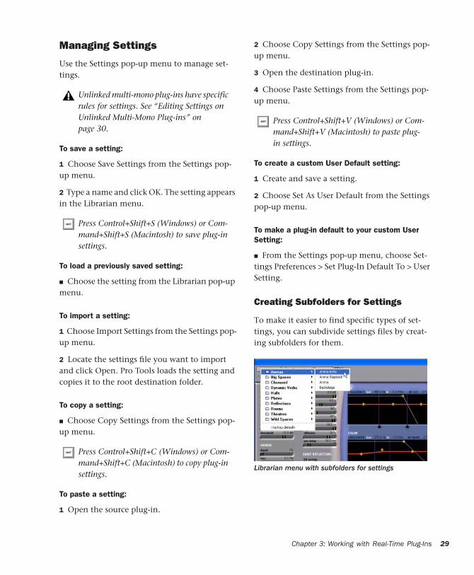
To make it easier to find specific types of set-tings, you can subdivide settings files by creat-ing subfolders for them.
Press Control+Shift+V (Windows) or Com-mand+Shift+V (Macintosh) to paste plug-in settings.
Librarian menu with subfolders for settings
Chapter 3: Working with Real-Time Plug-Ins 29
30
To create a settings subfolder:
1 From the Settings pop-up menu, choose Save Settings As.
2 Click the New Folder button and type a name for the subfolder.
3 Name the setting and click Save. The setting is saved within the subfolder.
Changing Settings with the Next (+) and Previous (–) Settings Buttons
The Next (+) and Previous (–) Settings buttons let you select the next or previous setting of the Librarian menu.
To change plug-in settings using the Next (+) and Previous (–) Settings buttons:
■ Press the Plus (+) or Minus (–) buttons to select the next or previous plug-in settings file. The next (or previous) settings file are enabled, and the Librarian menu changes to reflect the new setting.
Editing Settings on Unlinked Multi-Mono Plug-ins
When a multi-mono plug-in is unlinked, im-porting, copying, pasting, or bypassing settings affects only the currently selected channel.
To apply an operation to all channels of an unlinked plug-in:
■ Hold down the Alt key (Windows) or Option key (Macintosh) while performing the com-mand.
Digidesign Plug-Ins Guide
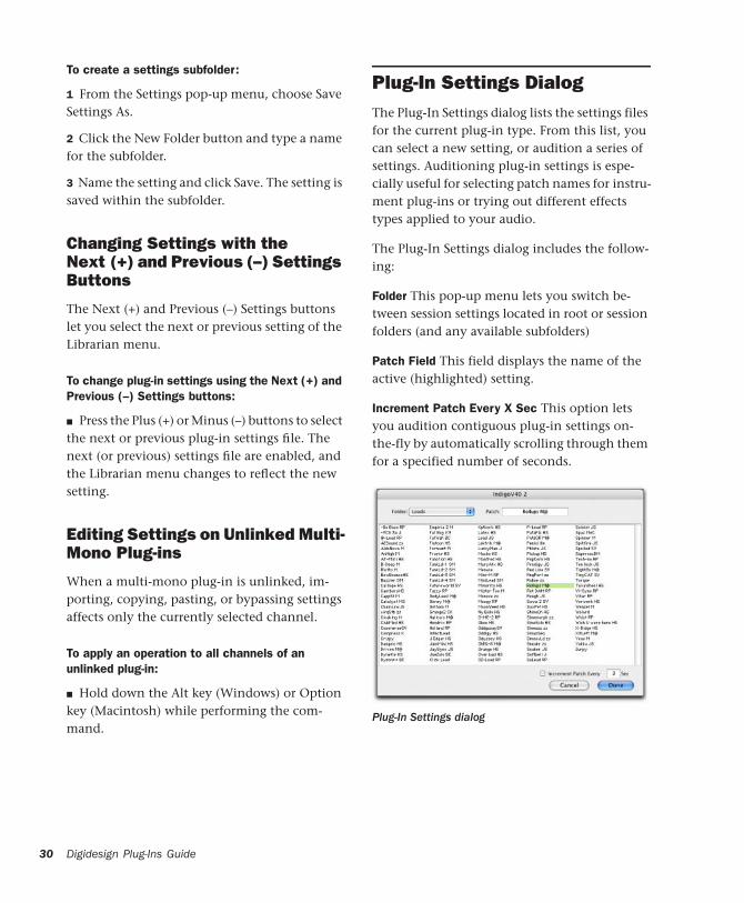
Plug-In Settings DialogThe Plug-In Settings dialog lists the settings files for the current plug-in type. From this list, you can select a new setting, or audition a series of settings. Auditioning plug-in settings is espe-cially useful for selecting patch names for instru-ment plug-ins or trying out different effects types applied to your audio.
The Plug-In Settings dialog includes the follow-ing:
Folder This pop-up menu lets you switch be-tween session settings located in root or session folders (and any available subfolders)
Patch Field This field displays the name of the active (highlighted) setting.
Increment Patch Every X Sec This option lets you audition contiguous plug-in settings on-the-fly by automatically scrolling through them for a specified number of seconds.
Plug-In Settings dialog
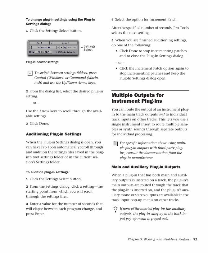
To change plug-in settings using the Plug-In Settings dialog:
1 Click the Settings Select button.
2 From the dialog list, select the desired plug-in setting.
– or –
Use the Arrow keys to scroll through the avail-able settings.
3 Click Done.
Auditioning Plug-in Settings
When the Plug-in Settings dialog is open, you can have Pro Tools automatically scroll through and audition the settings files saved in the plug-in’s root settings folder or in the current ses-sion’s Settings folder.
To audition plug-in settings:
1 Click the Settings Select button.
2 From the Settings dialog, click a setting—the starting point from which you will scroll through the settings files.
3 Enter a value for the number of seconds that will elapse between each program change, and press Enter.
Plug-in header settings
To switch between settings folders, press Control (Windows) or Command (Macin-tosh) and use the Up/Down Arrow keys.
Settings Select
4 Select the option for Increment Patch.
After the specified number of seconds, Pro Tools selects the next setting.
5 When you are finished auditioning settings, do one of the following:
• Click Done to stop incrementing patches, and to close the Plug-In Settings dialog.
– or –
• Click the Increment Patch option again to stop incrementing patches and keep the Plug-In Settings dialog open.
Multiple Outputs for Instrument Plug-InsYou can route the output of an instrument plug-in to the main track outputs and to individual track inputs on other tracks. This lets you use a single instrument insert to route multiple sam-ples or synth sounds through separate outputs for individual processing.
Main and Auxiliary Plug-In Outputs
When a plug-in that has both main and auxil-iary outputs is inserted on a track, the plug-in’s main outputs are routed through the track that the plug-in is inserted on, and the plug-in’s aux-iliary mono or stereo outputs are available in the track input pop-up menu on other tracks.
For specific information about using multi-ple plug-in outputs with third-party plug-ins, consult the documentation from the plug-in manufacturer.
If none of the inserted plug-ins has auxiliary outputs, the plug-in category in the track in-put pop-up menu is grayed out.
Chapter 3: Working with Real-Time Plug-Ins 31
32
HTDM Plug-In Conversion to RTASWhen you use Pro Tools 7.0 or later to open a session that was last saved in a version of Pro Tools prior to 7.0, most HTDM plug-ins will be automatically converted to their RTAS coun-terparts.
However, in rare cases as with some third-party plug-ins, these plug-ins will not automatically convert to RTAS and display as inactive. This means that the plug-in either has not been con-figured for automatic conversion or that no RTAS version is available.
In such cases, you must manually convert each individual HTDM plug-in to its RTAS counter-part. If an RTAS version is not available, the HTDM version will remain inactive.
When HTDM plug-ins are converted to RTAS, any RTAS plug-ins that precede TDM plug-ins on audio tracks will be by-passed if you enable Record Enable or TrackInput monitoring on that track. See “Ordering RTAS and TDM Plug-Ins on an Audio Track” on page 33 for details.
Digidesign Plug-Ins Guide
RTAS Plug-Ins on Auxiliary Input and Master Fader Tracks(Pro Tools HD Only)
In Pro Tools HD 7.0, RTAS plug-ins can be in-serted on Auxiliary Input and Master Fader tracks, or after TDM plug-ins on any kind of track.
This also affects the following RTAS-related be-havior in Pro Tools:
• Voice usage and total latency for RTAS plug-ins
• Limitations on inserting or removing plug-ins during playback
While HTDM plug-ins have a fixed buffer size, latency caused by RTAS plug-ins is ad-justable via the HW Buffer Size setting in the Playback Engine dialog. For more infor-mation, see the Pro Tools Reference Guide.
When you use Pro Tools 6.9.x or lower to open a session originally created with Pro Tools 7.0, any RTAS plug-ins inserted on Auxiliary Input or Master Fader tracks—or after TDM plug-ins on any kind of track—will become inactive.
Voice Usage and Total Latency for RTAS Plug-Ins
With Pro Tools HD, the initial insert of an RTAS plug-in may cause additional latency, and will take up two additional voices per channel (1 voice for input and 1 voice for output) in the following conditions:
• When inserted on an Auxiliary Input or Master Fader track
• When inserted on an Instrument track that does not contain an instrument plug-in
• When inserted after a TDM plug-in on any kind of track
For example, the initial insert of an RTAS plug-in on a mono Auxiliary Input track uses two voices (1 channel with 2 voices), while the ini-tial insert of that plug-in on a stereo Auxiliary In-put track uses four voices (2 channels with 2 voices each).
Subsequent RTAS plug-ins on the same track do not take up additional voices unless a TDM plug-in is inserted between other RTAS plug-ins.
Furthermore, one additional voice is used for each occurrence of any of the following condi-tions when using voices for RTAS plug-ins on a track:
• When you use an external side-chain for an RTAS plug-in on that track
• When you select multiple outputs for that track (one voice used for each output)
• When you select an AFL/PFL Path output in the Output tab of the I/O Setup dialog (one voice used for each channel)
Avoid inserting TDM plug-ins between RTAS plug-ins on any kind of track—this causes unnecessary voice usage and may cause additional latency.
Ordering RTAS and TDM Plug-Ins on an Audio Track
When RTAS and TDM plug-ins are combined on an audio track on a Pro Tools|HD system, the or-der in which they are inserted has different re-sults:
RTAS Plug-Ins Grouped Before TDM Plug-Ins No additional voices will be used, and no process-ing latency will occur. RTAS plug-ins will be by-passed when Record Enable or TrackInput mon-itoring is enabled for that track.
TDM Plug-Ins Grouped Before RTAS Plug-Ins
Each initial insert of an RTAS plug-in after a TDM plug-in will cause processing latency, and will use voices as described in “Voice Usage and Total Latency for RTAS Plug-Ins” on page 33. RTAS plug-ins will stay active while Record En-able or TrackInput monitoring is enabled for that track.
Ordering Recommendations
When combining RTAS and TDM plug-ins on an audio track, use one of the following two strategies based on your recording needs:
• To ensure that RTAS plug-ins stay active when you record enable a track or use TrackInput monitoring, group all TDM plug-ins before RTAS plug-ins.
– or –
• To conserve voices and minimize processing latency, group all RTAS plug-ins before TDM plug-ins.
As a rule, always group plug-ins of the same type together, especially if inserting RTAS after TDM plug-ins. Otherwise, additional voices may be unnecessarily used, and un-necessary latency may result.
Chapter 3: Working with Real-Time Plug-Ins 33
34
Limitations for Inserting or Removing Plug-Ins During Playback
When playing back tracks containing RTAS plug-ins, the following limitations on inserting or removing plug-ins apply:
• RTAS and TDM plug-ins cannot be inserted on or removed from Auxiliary Input, Mas-ter Fader, or Instrument tracks.
• An RTAS plug-in cannot be inserted after a TDM plug-in on an audio track, or removed from an audio track if it comes after a TDM plug-in.
• A TDM plug-in cannot be inserted before an RTAS plug-in on an audio track, or re-moved from an audio track if it comes be-fore an RTAS plug-in.
Digidesign Plug-Ins Guide
chapter 4
Working with AudioSuite Plug-Ins
AudioSuite plug-ins differ from TDM and RTAS plug-ins in that they are used to process and modify audio files on disk rather than non-destructively in real time. Depending on how you configure a non-real-time AudioSuite plug-in, it will either alter the original source audio file or create an entirely new audio source file.
The AudioSuite MenuAudioSuite plug-ins are accessed through the AudioSuite menu.
Plug-ins can be organized in the AudioSuite menu in Pro Tools by Flat List (with plug-ins in alphabetical order), Category, Manufacturer, or Category and Manufacturer.
For more information, see “Organizing Plug-Ins” on page 15.
The AudioSuite WindowWhen you choose a plug-in from the AudioSuite menu, the AudioSuite window ap-pears. From this floating window you can access and edit the controls for any non-real-time AudioSuite plug-in.
AudioSuite controls
Settingsmenu
Librarianmenu
File Mode selector
Plug-Inselector
Compare button
ProcessMode selector
SelectionReference
Use in Playlistbutton
Previewbutton
Bypassbutton
Processbutton
Previous setting
Next setting
SettingsSelect
Chapter 4: Working with
AudioS uite Plug-Ins 35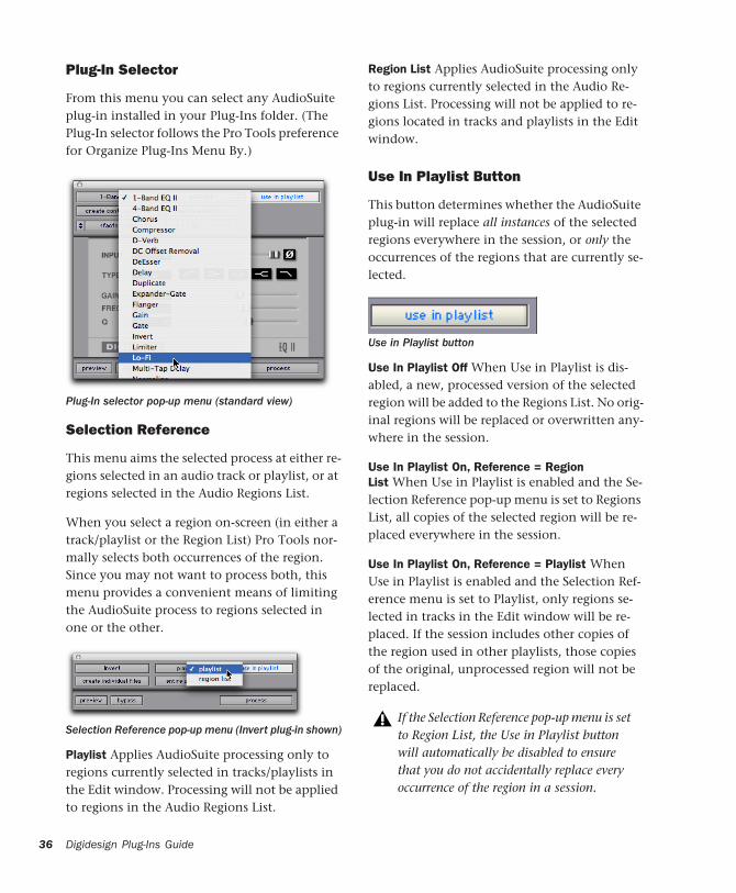
36
Plug-In Selector
From this menu you can select any AudioSuite plug-in installed in your Plug-Ins folder. (The Plug-In selector follows the Pro Tools preference for Organize Plug-Ins Menu By.)
Selection Reference
This menu aims the selected process at either re-gions selected in an audio track or playlist, or at regions selected in the Audio Regions List.
When you select a region on-screen (in either a track/playlist or the Region List) Pro Tools nor-mally selects both occurrences of the region. Since you may not want to process both, this menu provides a convenient means of limiting the AudioSuite process to regions selected in one or the other.
Playlist Applies AudioSuite processing only to regions currently selected in tracks/playlists in the Edit window. Processing will not be applied to regions in the Audio Regions List.
Plug-In selector pop-up menu (standard view)
Selection Reference pop-up menu (Invert plug-in shown)
Digidesign Plug-Ins Guide
Region List Applies AudioSuite processing only to regions currently selected in the Audio Re-gions List. Processing will not be applied to re-gions located in tracks and playlists in the Edit window.
Use In Playlist Button
This button determines whether the AudioSuite plug-in will replace all instances of the selected regions everywhere in the session, or only the occurrences of the regions that are currently se-lected.
Use In Playlist Off When Use in Playlist is dis-abled, a new, processed version of the selected region will be added to the Regions List. No orig-inal regions will be replaced or overwritten any-where in the session.
Use In Playlist On, Reference = Region List When Use in Playlist is enabled and the Se-lection Reference pop-up menu is set to Regions List, all copies of the selected region will be re-placed everywhere in the session.
Use In Playlist On, Reference = Playlist When Use in Playlist is enabled and the Selection Ref-erence menu is set to Playlist, only regions se-lected in tracks in the Edit window will be re-placed. If the session includes other copies of the region used in other playlists, those copies of the original, unprocessed region will not be replaced.
Use in Playlist button
If the Selection Reference pop-up menu is set to Region List, the Use in Playlist button will automatically be disabled to ensure that you do not accidentally replace every occurrence of the region in a session.
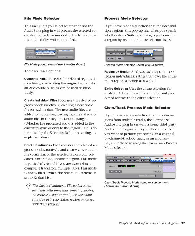
File Mode Selector
This menu lets you select whether or not the AudioSuite plug-in will process the selected au-dio destructively or nondestructively, and how the original files will be modified.
There are three options:
Overwrite Files Processes the selected regions de-structively, overwriting the original audio. Not all AudioSuite plug-ins can be used destruc-tively.
Create Individual Files Processes the selected re-gions nondestructively, creating a new audio file for each region. The new audio files are added to the session, leaving the original source audio files in the Regions List unchanged. (Whether the processed audio is added to the current playlist or only to the Regions List, is de-termined by the Selection Reference setting, as explained above.)
Create Continuous File Processes the selected re-gions nondestructively and creates a new audio file consisting of the selected regions consoli-dated into a single, unbroken region. This mode is particularly useful if you are assembling a composite track from multiple takes. This mode is not available when the Selection Reference is set to Region List.
File Mode pop-up menu (Invert plug-in shown)
The Create Continuous File option is not available with some time domain plug-ins. To achieve a similar result, use the Dupli-cate plug-in to consolidate regions processed with these plug-ins.
Process Mode Selector
If you have made a selection that includes mul-tiple regions, this pop-up menu lets you specify whether AudioSuite processing is performed on a region-by-region, or entire-selection basis.
Region by Region Analyzes each region in a se-lection individually, rather than over the entire multi-region selection as a whole.
Entire Selection Uses the entire selection for analysis. All regions will be analyzed and pro-cessed relative to the entire selection.
Chan/Track Process Mode Selector
If you have made a selection that includes re-gions from multiple tracks, the Normalize AudioSuite plug-in (as well as some third-party AudioSuite plug-ins) lets you choose whether you want to perform processing on a channel-by-channel/track-by-track, or an all-chan-nel/all-tracks basis using the Chan/Track Process Mode selector.
Process Mode selector (Invert plug-in shown)
Chan/Track Process Mode selector pop-up menu (Normalize plug-in shown)
Chapter 4: Working with AudioSuite Plug-Ins 37
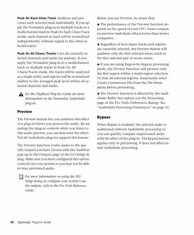
38
Peak On Each Chan/Track Analyzes and pro-cesses each selected track individually. If you ap-ply the Normalize plug-in to multiple tracks or a multichannel track in Peak On Each Chan/Track mode, each channel or track will be normalized independently, without regard to the other se-lected tracks.
Peak On All Chans/Tracks Uses all currently se-lected channels and tracks for analysis. If you apply the Normalize plug-in to a multichannel track or multiple tracks in Peak On All Chans/Tracks mode, the tracks will be analyzed as a single entity and regions will be normalized relative to the averaged peak level within all se-lected channels and tracks.
Preview
The Preview button lets you audition the effect of a plug-in before you process the audio. By ad-justing the plug-in controls while you listen to this audio preview, you can fine-tune the effect. Not all AudioSuite plug-ins support this feature.
The Preview function routes audio to the spe-cific outputs you have chosen with the Audition pop-up in the Outputs page of the I/O Setup di-alog. Make sure you have configured this option correctly for your system or you may not be able to hear previewed audio.
See the DigiRack Plug-Ins Guide for more information on the Normalize AudioSuite plug-in.
For more information on using the I/O Setup dialog to configure your system’s au-dio outputs, refer to the Pro Tools Reference Guide.
Digidesign Plug-Ins Guide
Before you use Preview, be aware that:
◆ The performance of the Preview function de-pends on the speed of your CPU. Faster comput-ers preview AudioSuite effects better than slower computers.
◆ Regardless of how many tracks and regions are currently selected, the Preview button will audition only the first selected stereo track or the first selected pair of mono tracks.
◆ If you are using Region-by-Region processing mode, the Preview function will preview only the first region within a multi-region selection. To hear all selected regions, temporarily select Create Continuous File from the File Mode menu before previewing.
◆ The Preview function is affected by the Audi-oSuite Buffer Size option (on the Processing page of the Pro Tools Preferences dialog). See “AudioSuite Processing Preferences” on page 41.
Bypass
When Bypass is enabled, the selected audio is auditioned without AudioSuite processing so you can quickly compare unprocessed audio with the affect of the plug-in. The Bypass button applies only to previewing. It does not affect ac-tual AudioSuite processing.
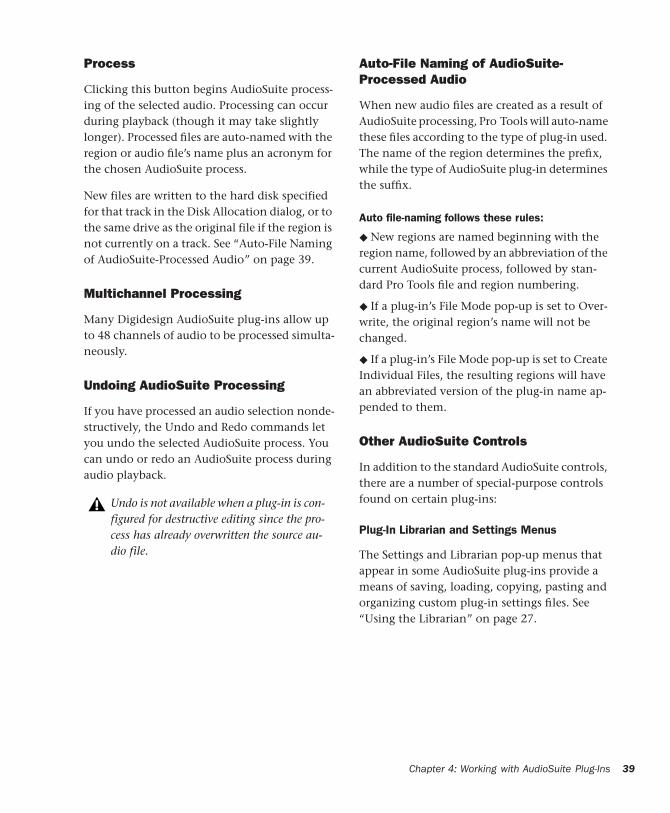
Process
Clicking this button begins AudioSuite process-ing of the selected audio. Processing can occur during playback (though it may take slightly longer). Processed files are auto-named with the region or audio file’s name plus an acronym for the chosen AudioSuite process.
New files are written to the hard disk specified for that track in the Disk Allocation dialog, or to the same drive as the original file if the region is not currently on a track. See “Auto-File Naming of AudioSuite-Processed Audio” on page 39.
Multichannel Processing
Many Digidesign AudioSuite plug-ins allow up to 48 channels of audio to be processed simulta-neously.
Undoing AudioSuite Processing
If you have processed an audio selection nonde-structively, the Undo and Redo commands let you undo the selected AudioSuite process. You can undo or redo an AudioSuite process during audio playback.
Undo is not available when a plug-in is con-figured for destructive editing since the pro-cess has already overwritten the source au-dio file.
Auto-File Naming of AudioSuite-Processed Audio
When new audio files are created as a result of AudioSuite processing, Pro Tools will auto-name these files according to the type of plug-in used. The name of the region determines the prefix, while the type of AudioSuite plug-in determines the suffix.
Auto file-naming follows these rules:
◆ New regions are named beginning with the region name, followed by an abbreviation of the current AudioSuite process, followed by stan-dard Pro Tools file and region numbering.
◆ If a plug-in’s File Mode pop-up is set to Over-write, the original region’s name will not be changed.
◆ If a plug-in’s File Mode pop-up is set to Create Individual Files, the resulting regions will have an abbreviated version of the plug-in name ap-pended to them.
Other AudioSuite Controls
In addition to the standard AudioSuite controls, there are a number of special-purpose controls found on certain plug-ins:
Plug-In Librarian and Settings Menus
The Settings and Librarian pop-up menus that appear in some AudioSuite plug-ins provide a means of saving, loading, copying, pasting and organizing custom plug-in settings files. See “Using the Librarian” on page 27.
Chapter 4: Working with AudioSuite Plug-Ins 39
40
Analyze Button
This button analyzes a selection without actu-ally processing it. “For example, on the DigiRack Gain plug-in, the Analyze feature lets you deter-mine the maximum peak level on a track at a specific gain value before you process the au-dio.”
Key Input Selector Lets you select a track or bus to be used to trigger processing. In order to use this feature, the key input source audio must oc-cur at the same time as the target audio. See “Us-ing the Side-Chain Input” on page 23.
Channel Mode button
The Channel Mode button lets you process con-tiguous channels within a selected region as though they were mono or stereo tracks (and in some cases greater-than-stereo tracks), regard-less of the type of tracks they occupy.
Mono mode Processes each contiguous channel within a selected region as a separate mono track. For example, a region comprised of six mono tracks would be processed as six mono tracks.
Stereo mode Processes each contiguous pair of channels within a selected region as a stereo track. When applied to an odd number of chan-nels, the plug-in processes the last odd, un-paired channel as mono, using the left channel settings of the stereo plug-in. If you want the last track to be processed in stereo, you must se-lect an additional track to pair it with—an empty one if necessary.
Side-chain inputs for plug-ins have no effect on AudioSuite processes when the Selection Reference is set to Region List.
Digidesign Plug-Ins Guide
For example, a region comprised of two mono tracks would be processed as a stereo track, with the first mono track processed as the left chan-nel and the second mono track processed as the right channel.
Multi mode Processes each set of three or more contiguous channels within a selected region as a multichannel greater-than-stereo track, with the number of selected channels determining the type of track. For example, five contigu-ously-selected channels would be processed as a 5.0 track, while seven contiguously-selected channels will be processed as a 7.1 track.
Multi mode is available only for certain plug-ins, such as Dynamics III.
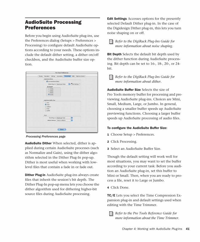
AudioSuite Processing PreferencesBefore you begin using AudioSuite plug-ins, use the Preferences dialog (Setups > Preferences > Processing) to configure default AudioSuite op-tions according to your needs. These options in-clude the default dither setting, a dither on/off checkbox, and the AudioSuite buffer size op-tion.
AudioSuite Dither When selected, dither is ap-plied during certain AudioSuite processes (such as Normalize and Gain), using the dither algo-rithm selected in the Dither Plug-In pop-up. Dither is most useful when working with low-level files that contain a fade in or fade out.
Dither Plug-in AudioSuite plug-ins always create files that inherit the session’s bit depth. The Dither Plug-In pop-up menu lets you choose the dither algorithm used for dithering higher-bit source files during AudioSuite processing.
Processing Preferences page
Edit Settings Accesses options for the presently selected Default Dither plug-in. In the case of the Digidesign Dither plug-in, this lets you turn noise shaping on or off.
Bit Depth Selects the default bit depth used by the dither function during AudioSuite process-ing. Bit depth can be set to 16-, 18-, 20-, or 24-bit.
AudioSuite Buffer Size Selects the size of Pro Tools memory buffer for processing and pre-viewing AudioSuite plug-ins. Choices are Mini, Small, Medium, Large, or Jumbo. In general, choosing a smaller buffer speeds up AudioSuite previewing functions. Choosing a larger buffer speeds up AudioSuite processing of audio files.
To configure the AudioSuite Buffer Size:
1 Choose Setup > Preferences.
2 Click Processing.
3 Select an AudioSuite Buffer Size.
Though the default setting will work well for most situations, you may want to set the buffer according to your current task: Before you audi-tion an AudioSuite plug-in, set this buffer to Mini or Small. Then, when you are ready to pro-cess a file, reset it to Large or Jumbo.
4 Click Done.
TC/E Lets you select the Time Compression Ex-pansion plug-in and default settings used when editing with the Time Trimmer.
Refer to the DigiRack Plug-Ins Guide for more information about noise shaping.
Refer to the DigiRack Plug-Ins Guide for more information about dither.
Refer to the Pro Tools Reference Guide for more information about the Time Trimmer.
Chapter 4: Working with AudioSuite Plug-Ins 41
42
Using AudioSuite Plug-InsAudioSuite plug-ins can be applied to whole re-gions, partial regions, or selections that are made up of whole and partial regions across one or more tracks.
The basic steps to use AudioSuite plug-ins are:
• Select (highlight) the audio in tracks that you want to process (see “Selecting Tracks for Au-dioSuite Processing” on page 42).
• Select an AudioSuite plug-in from the Audio-Suite menu.
• Configure plug-in parameters as needed.
• Process the selected audio with the current AudioSuite plug-in settings.
When audio selected in the Edit window in-cludes partial regions, the regions will automat-ically be split into two or more regions when they are processed. Processing will occur only on the selection, leaving other regions un-changed.
Only audio files on locally connected hard drives can be processed with AudioSuite plug-ins. You cannot process audio files on remote hard drives over a network.
Processing a locked region will cause the re-gion to become unlocked, and processing a muted region will cause it to become un-muted. For more information on locked and muted regions, refer to the Pro Tools Refer-ence Guide.
Digidesign Plug-Ins Guide
Selecting Tracks for AudioSuite Processing
Because AudioSuite processes are performed on the specific regions that you select, it is impor-tant that you select only those regions, or parts of regions, you actually want to process.
Selecting a region in the Audio Regions List will automatically select it in a track (if it currently resides on one). This is the default behavior for Pro Tools. However, you can change this using the Region Selection Follows Track Selection, or Track Selection Follows Regions List Selection options in the Editing page of the Preferences di-alog. See the Pro Tools Reference Guide for an ex-planation of these Preferences.
Selecting Tracks for Delay or Reverb Processing
Because some AudioSuite effects such as delay and reverb add additional material to the end of the selected audio (a reverb tail or a delay tap), it is very important that you make a selection that is longer than the original source material so that the plug-in can write it into the audio file.
If you select only the original material, without leaving additional space at the end, a reverb de-cay or delay that occurs after the end of the re-gion will be cut off.
To compensate for this, place the region in a track and select the desired audio plus an amount of blank space at the end of the region equal to the amount of delay or reverb decay that you have added in the plug-in. The plug-in will then have space at the end of the region in which to write the final delay or decay.
When processing a single audio channel with an AudioSuite plug-in, make sure that the plug-in is set to Mono mode (if avail-able).
If you select more blank space than you need, you can remove it using the Trim tool after ap-plying AudioSuite processing.
To process audio with an AudioSuite plug-in:
1 Select regions to process in one or more target tracks and/or in the Audio Regions List. Shift-click to select multiple regions. Only regions that are selected will be processed.
2 Choose the desired AudioSuite plug-in from the AudioSuite menu.
3 Click the Preview button to begin playback of the selected material.
4 Adjust the plug-in controls to achieve the ef-fect that you want. These settings will determine how the file is processed and what effect the processing will have on the original regions. Fol-low these guidelines:
• To process the selected region only in the track in which it appears, select Playlist from the Selection Reference pop-up. Alter-natively, if you want to process the selected region in the Audio Regions list only, choose Region List from this pop-up.
• If you want to process and update every oc-currence of the selected region throughout your session, enable the Use In Playlist but-ton (and also select Region List from the Se-lection Reference pop-up). Alternatively, if you do not want to update every occur-rence of the selected region, deselect the Use In Playlist button.
• To configure the plug-in for destructive processing, select Overwrite Files from the File Mode pop-up menu. This will over-write and permanently modify the original source audio files.
• Alternatively, to configure the plug-in for nondestructive processing, select Create Individual Files from the File Mode pop-up menu. This will create new audio files that have been processed with the AudioSuite Plug-in and leave the original source audio files untouched.
• If you have selected multiple regions for processing and want to create a new file that connects and consolidates all of these regions together, select Create Continuous File from the File Mode pop-up menu.
5 Finally, when you are ready, click the Process button.
The selected audio is processed according to the settings you have specified. Pro Tools appends an acronym to the region’s name indicating the AudioSuite process that has been applied. The new audio files then appear in your session.
Using AudioSuite Plug-Ins in Stereo
Some AudioSuite plug-ins can be used in either mono or stereo. If you plan to use them in ste-reo, be aware of the following:
◆ To process a mono track and obtain a stereo result, select the desired track or region plus an empty track or region. Then set the plug-in to Stereo mode and select the Sum Inputs button (if present) to center the dry signal. When you process the audio, the result will be two tracks or regions that represent the right and left chan-nels of the processed audio. You should then pan these tracks hard right and hard left in your mix.
◆ If you set a plug-in to Stereo mode, then select an odd number of Pro Tools tracks for process-ing (as opposed to an even number), the plug-in will process the selected tracks in pairs, in stereo. However, the last odd, unpaired track will be
Chapter 4: Working with AudioSuite Plug-Ins 43
44
processed as mono, using the left channel set-tings of the stereo plug-in. If you want the last track to be processed in stereo, you must select an additional track to pair it with—an empty one if necessary.
See “Channel Mode button” on page 40 for more information.
Digidesign Plug-Ins Guide
chapter 5
D-Fi
D-Fi consists of four separate plug-ins for TDM, RTAS, and AudioSuite. D-Fi plug-ins form a unique sound design tool kit for processing and deconstructing audio in several retro and syn-thesis-oriented ways.
Lo-Fi
Lo-Fi provides retro and down-processing ef-fects, including:
• Bit-rate reduction
• Sample rate reduction
• Soft clipping distortion and saturation
• Anti-aliasing filter
• Variable amplitude noise generator
Lo-Fi can be used as either a real-time TDM or RTAS plug-in or as a non-real-time AudioSuite plug-in.
The multichannel TDM version of the Lo-Fi plug-in is not supported at 192 kHz, use the multi-mono TDM or RTAS version instead.
Sci-Fi
Sci-Fi provides analog synthesizer-type effects, including:
• Ring modulation
• Frequency modulation
• Variable-frequency, positive and negative resonator
• Modulation control by LFO, envelope fol-lower, sample-and-hold, or trigger-and-hold
Sci-Fi can be used as either a real-time TDM or RTAS plug-in or as a non-real-time AudioSuite plug-in.
The multichannel TDM version of the Sci-Fi plug-in is not supported at 192 kHz. Use the multi-mono TDM or RTAS version instead.
Chapter 5: D-Fi 45
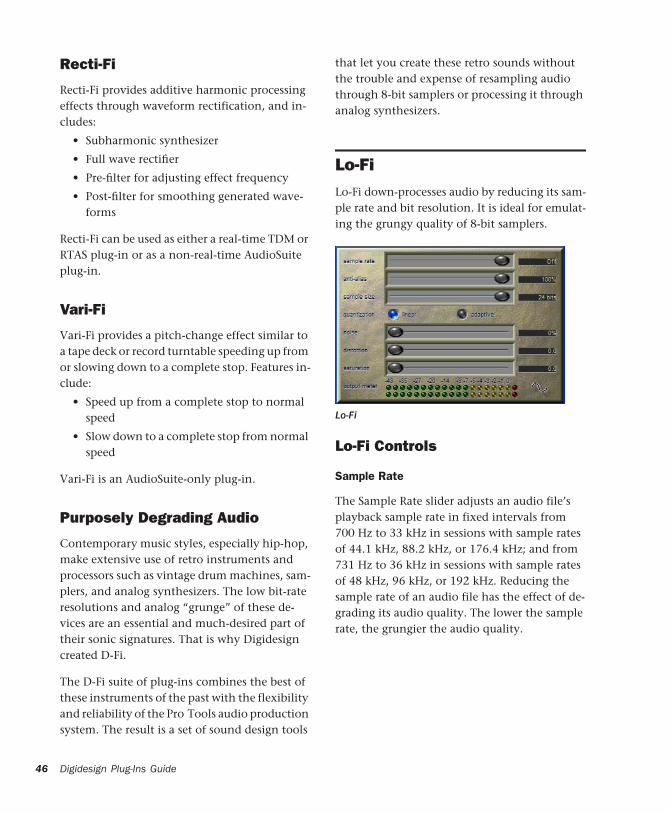
46
Recti-Fi
Recti-Fi provides additive harmonic processing effects through waveform rectification, and in-cludes:
• Subharmonic synthesizer
• Full wave rectifier
• Pre-filter for adjusting effect frequency
• Post-filter for smoothing generated wave-forms
Recti-Fi can be used as either a real-time TDM or RTAS plug-in or as a non-real-time AudioSuite plug-in.
Vari-Fi
Vari-Fi provides a pitch-change effect similar to a tape deck or record turntable speeding up from or slowing down to a complete stop. Features in-clude:
• Speed up from a complete stop to normal speed
• Slow down to a complete stop from normal speed
Vari-Fi is an AudioSuite-only plug-in.
Purposely Degrading Audio
Contemporary music styles, especially hip-hop, make extensive use of retro instruments and processors such as vintage drum machines, sam-plers, and analog synthesizers. The low bit-rate resolutions and analog “grunge” of these de-vices are an essential and much-desired part of their sonic signatures. That is why Digidesign created D-Fi.
The D-Fi suite of plug-ins combines the best of these instruments of the past with the flexibility and reliability of the Pro Tools audio production system. The result is a set of sound design tools
Digidesign Plug-Ins Guide
that let you create these retro sounds without the trouble and expense of resampling audio through 8-bit samplers or processing it through analog synthesizers.
Lo-FiLo-Fi down-processes audio by reducing its sam-ple rate and bit resolution. It is ideal for emulat-ing the grungy quality of 8-bit samplers.
Lo-Fi Controls
Sample Rate
The Sample Rate slider adjusts an audio file’s playback sample rate in fixed intervals from 700 Hz to 33 kHz in sessions with sample rates of 44.1 kHz, 88.2 kHz, or 176.4 kHz; and from 731 Hz to 36 kHz in sessions with sample rates of 48 kHz, 96 kHz, or 192 kHz. Reducing the sample rate of an audio file has the effect of de-grading its audio quality. The lower the sample rate, the grungier the audio quality.
Lo-Fi

The maximum value of the Sample Rate control is Off (which effectively means bypass).
Anti-Alias Filter
The Anti-Alias filter works in conjunction with the Sample Rate control. As you reduce the sam-ple rate, aliasing artifacts are produced in the au-dio. These produce a characteristically dirty sound. Lo-Fi’s anti-alias filter has a default set-ting of 100%, automatically removing all alias-ing artifacts as the sample rate is lowered.
This control is adjustable from 0% to 100%, let-ting you add precisely the amount of aliasing you want back into the mix. This slider only has an effect if you have reduced the sample rate with the Sample Rate control.
Sample Size
The Sample Size slider controls the bit resolu-tion of the audio. Like sample rate, bit resolu-tion affects audio quality and clarity. The lower the bit resolution, the grungier the quality. The range of this control is from 24 bits to 2 bits.
Quantization
Lo-Fi applies quantization to impose the se-lected bit size on the target audio signal. The type of quantization performed can also affect the character of an audio signal. Lo-Fi provides you with a choice of linear or adaptive quantiza-tion.
Linear Linear quantization abruptly cuts off sample data bits in an effort to fit the audio into the selected bit resolution. This imparts a char-acteristically raunchy sound to the audio that
The range of the Sample Rate control is slightly different at different session sample rates because Lo-Fi’s subsampling is calcu-lated by integer ratios of the session sample rate.
becomes more pronounced as the sample size is reduced. At extreme low bit-resolution settings, linear quantization will actually cause abrupt cut-offs in the signal itself, similar to gating. Thus, linear resolution can be used creatively to add random percussive, rhythmic effects to the audio signal when it falls to lower levels, and a grungy quality as the audio reaches mid-levels.
Adaptive Adaptive quantization reduces bit depth by adapting to changes in level by track-ing and shifting the amplitude range of the sig-nal. This shifting causes the signal to fit into the lower bit range. The result is a higher apparent bit resolution with a raunchiness that differs from the harsher quantization scheme used in linear resolution.
Noise Generator
The Noise slider mixes a percentage of pseudo-white noise into the audio signal. Noise is useful for adding grit into a signal, especially when you are processing percussive sounds. This noise is shaped by the envelope of the input signal. The range of this control is from 0 to 100%. When noise is set to 100%, the original signal and the noise are equal in level.
Distortion/Saturation
The Distortion and Saturation sliders provide signal clipping control. The Distortion slider de-termines the amount of gain applied and lets clipping occur in a smooth, rounded manner.
The Saturation slider determines the amount of saturation added to the signal. This simulates the effect of tube saturation with a roll-off of high frequencies.
Fans of Spinal Tap will be pleased to know that the Distortion and Saturation controls can be set to eleven for maximum effect.
Chapter 5: D-Fi 47
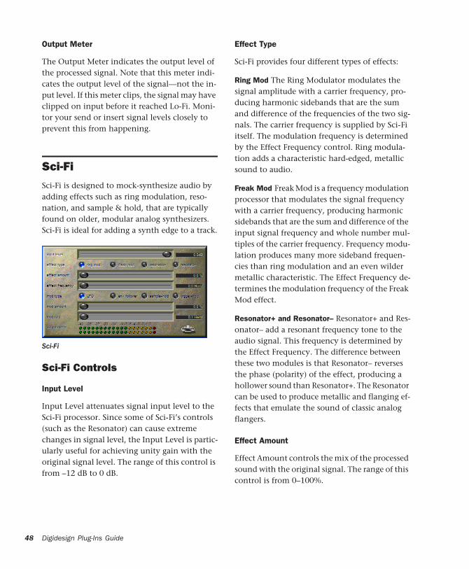
48
Output Meter
The Output Meter indicates the output level of the processed signal. Note that this meter indi-cates the output level of the signal—not the in-put level. If this meter clips, the signal may have clipped on input before it reached Lo-Fi. Moni-tor your send or insert signal levels closely to prevent this from happening.
Sci-FiSci-Fi is designed to mock-synthesize audio by adding effects such as ring modulation, reso-nation, and sample & hold, that are typically found on older, modular analog synthesizers. Sci-Fi is ideal for adding a synth edge to a track.
Sci-Fi Controls
Input Level
Input Level attenuates signal input level to the Sci-Fi processor. Since some of Sci-Fi’s controls (such as the Resonator) can cause extreme changes in signal level, the Input Level is partic-ularly useful for achieving unity gain with the original signal level. The range of this control is from –12 dB to 0 dB.
Sci-Fi
Digidesign Plug-Ins Guide
Effect Type
Sci-Fi provides four different types of effects:
Ring Mod The Ring Modulator modulates the signal amplitude with a carrier frequency, pro-ducing harmonic sidebands that are the sum and difference of the frequencies of the two sig-nals. The carrier frequency is supplied by Sci-Fi itself. The modulation frequency is determined by the Effect Frequency control. Ring modula-tion adds a characteristic hard-edged, metallic sound to audio.
Freak Mod Freak Mod is a frequency modulation processor that modulates the signal frequency with a carrier frequency, producing harmonic sidebands that are the sum and difference of the input signal frequency and whole number mul-tiples of the carrier frequency. Frequency modu-lation produces many more sideband frequen-cies than ring modulation and an even wilder metallic characteristic. The Effect Frequency de-termines the modulation frequency of the Freak Mod effect.
Resonator+ and Resonator– Resonator+ and Res-onator– add a resonant frequency tone to the audio signal. This frequency is determined by the Effect Frequency. The difference between these two modules is that Resonator– reverses the phase (polarity) of the effect, producing a hollower sound than Resonator+. The Resonator can be used to produce metallic and flanging ef-fects that emulate the sound of classic analog flangers.
Effect Amount
Effect Amount controls the mix of the processed sound with the original signal. The range of this control is from 0–100%.
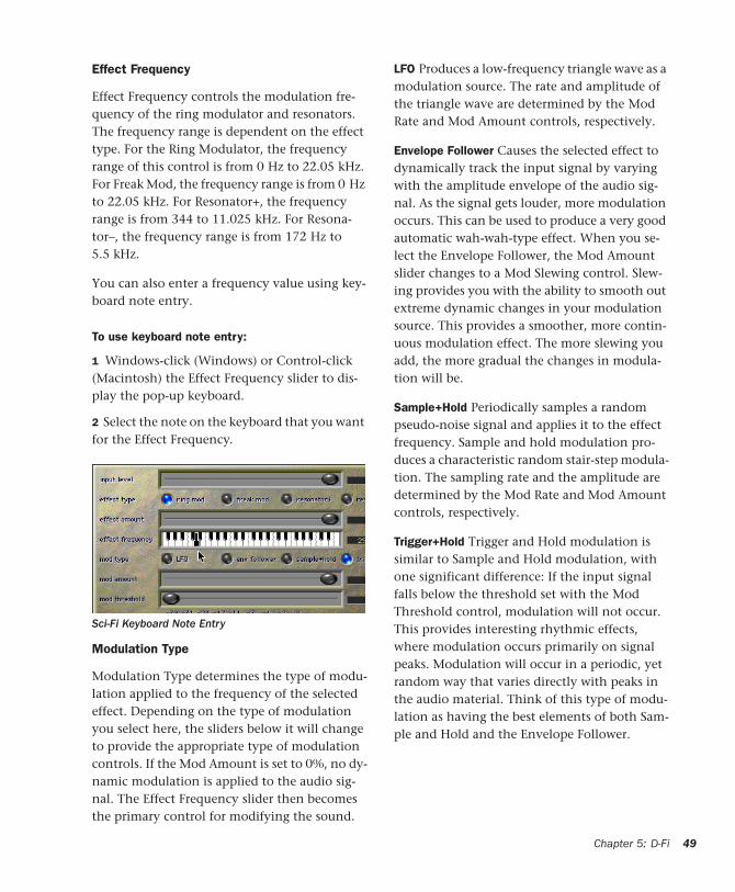
Effect Frequency
Effect Frequency controls the modulation fre-quency of the ring modulator and resonators. The frequency range is dependent on the effect type. For the Ring Modulator, the frequency range of this control is from 0 Hz to 22.05 kHz. For Freak Mod, the frequency range is from 0 Hz to 22.05 kHz. For Resonator+, the frequency range is from 344 to 11.025 kHz. For Resona-tor–, the frequency range is from 172 Hz to 5.5 kHz.
You can also enter a frequency value using key-board note entry.
To use keyboard note entry:
1 Windows-click (Windows) or Control-click (Macintosh) the Effect Frequency slider to dis-play the pop-up keyboard.
2 Select the note on the keyboard that you want for the Effect Frequency.
Modulation Type
Modulation Type determines the type of modu-lation applied to the frequency of the selected effect. Depending on the type of modulation you select here, the sliders below it will change to provide the appropriate type of modulation controls. If the Mod Amount is set to 0%, no dy-namic modulation is applied to the audio sig-nal. The Effect Frequency slider then becomes the primary control for modifying the sound.
Sci-Fi Keyboard Note Entry
LFO Produces a low-frequency triangle wave as a modulation source. The rate and amplitude of the triangle wave are determined by the Mod Rate and Mod Amount controls, respectively.
Envelope Follower Causes the selected effect to dynamically track the input signal by varying with the amplitude envelope of the audio sig-nal. As the signal gets louder, more modulation occurs. This can be used to produce a very good automatic wah-wah-type effect. When you se-lect the Envelope Follower, the Mod Amount slider changes to a Mod Slewing control. Slew-ing provides you with the ability to smooth out extreme dynamic changes in your modulation source. This provides a smoother, more contin-uous modulation effect. The more slewing you add, the more gradual the changes in modula-tion will be.
Sample+Hold Periodically samples a random pseudo-noise signal and applies it to the effect frequency. Sample and hold modulation pro-duces a characteristic random stair-step modula-tion. The sampling rate and the amplitude are determined by the Mod Rate and Mod Amount controls, respectively.
Trigger+Hold Trigger and Hold modulation is similar to Sample and Hold modulation, with one significant difference: If the input signal falls below the threshold set with the Mod Threshold control, modulation will not occur. This provides interesting rhythmic effects, where modulation occurs primarily on signal peaks. Modulation will occur in a periodic, yet random way that varies directly with peaks in the audio material. Think of this type of modu-lation as having the best elements of both Sam-ple and Hold and the Envelope Follower.
Chapter 5: D-Fi 49
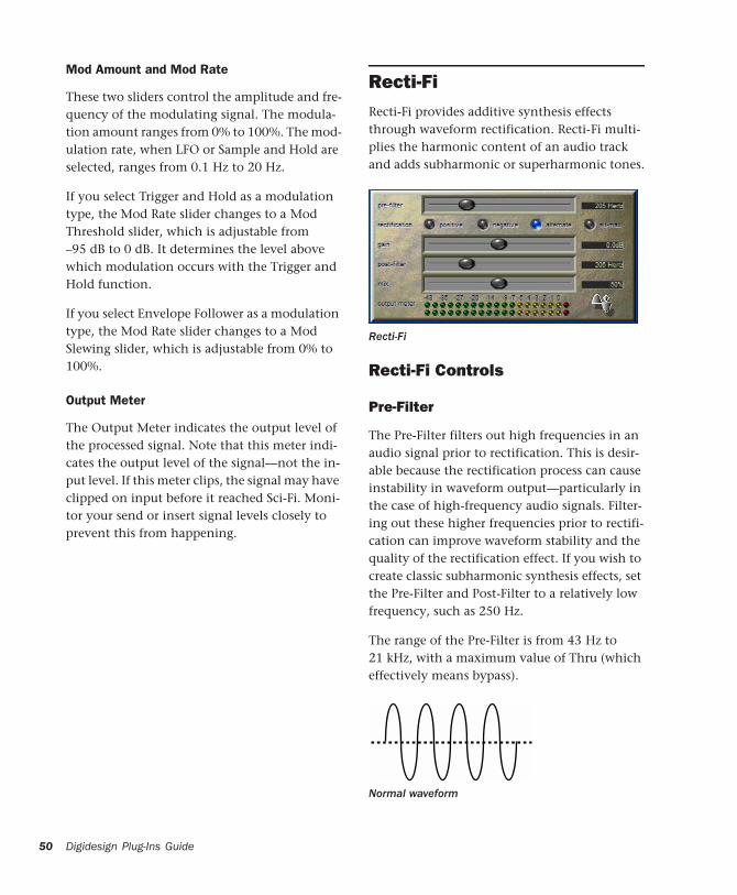
50
Mod Amount and Mod Rate
These two sliders control the amplitude and fre-quency of the modulating signal. The modula-tion amount ranges from 0% to 100%. The mod-ulation rate, when LFO or Sample and Hold are selected, ranges from 0.1 Hz to 20 Hz.
If you select Trigger and Hold as a modulation type, the Mod Rate slider changes to a Mod Threshold slider, which is adjustable from –95 dB to 0 dB. It determines the level above which modulation occurs with the Trigger and Hold function.
If you select Envelope Follower as a modulation type, the Mod Rate slider changes to a Mod Slewing slider, which is adjustable from 0% to 100%.
Output Meter
The Output Meter indicates the output level of the processed signal. Note that this meter indi-cates the output level of the signal—not the in-put level. If this meter clips, the signal may have clipped on input before it reached Sci-Fi. Moni-tor your send or insert signal levels closely to prevent this from happening.
Digidesign Plug-Ins Guide
Recti-FiRecti-Fi provides additive synthesis effects through waveform rectification. Recti-Fi multi-plies the harmonic content of an audio track and adds subharmonic or superharmonic tones.
Recti-Fi Controls
Pre-Filter
The Pre-Filter filters out high frequencies in an audio signal prior to rectification. This is desir-able because the rectification process can cause instability in waveform output—particularly in the case of high-frequency audio signals. Filter-ing out these higher frequencies prior to rectifi-cation can improve waveform stability and the quality of the rectification effect. If you wish to create classic subharmonic synthesis effects, set the Pre-Filter and Post-Filter to a relatively low frequency, such as 250 Hz.
The range of the Pre-Filter is from 43 Hz to 21 kHz, with a maximum value of Thru (which effectively means bypass).
Recti-Fi
Normal waveform

Rectification
Positive Rectification
This rectifies the waveform so that its phase is 100% positive. The audible effect is a doubling of the audio signal’s frequency.
Negative Rectification
This rectifies the waveform so that its phase is 100% negative. The audible effect is a doubling of the audio signal’s frequency.
Alternating Rectification
This alternates between rectifying the phase of the first negative waveform excursion to posi-tive, then the next positive excursion to nega-tive, and so on, throughout the waveform. The audible effect is a halving of the audio signal’s frequency, creating a subharmonic tone.
Positive rectification
Negative rectification
Alternating rectification
Alt-Max Rectification
This alternates between holding the maximum value of the first positive excursion through the negative excursion period, switching to rectify the next positive excursion, and holding its peak negative value until the next zero crossing. The audible effect is a halving of the audio sig-nal’s frequency, and creating a subharmonic tone with a hollow, square wave-like timbre.
Gain
Gain lets you adjust signal level before the audio reaches the Post-Filter. This is particularly useful for restoring unity gain if you have used the Pre-Filter to cut off high frequencies prior to rectifi-cation. The range of this control is from –18dB to +18dB.
Alt-Max rectification
Chapter 5: D-Fi 51
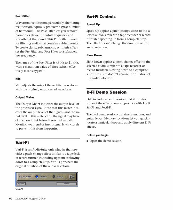
52
Post-Filter
Waveform rectification, particularly alternating rectification, typically produces a great number of harmonics. The Post Filter lets you remove harmonics above the cutoff frequency and smooth out the sound. This Post-Filter is useful for filtering audio that contains subharmonics. To create classic subharmonic synthesis effects, set the Pre-Filter and Post-Filter to a relatively low frequency.
The range of the Post-Filter is 43 Hz to 21 kHz, with a maximum value of Thru (which effec-tively means bypass).
Mix
Mix adjusts the mix of the rectified waveform with the original, unprocessed waveform.
Output Meter
The Output Meter indicates the output level of the processed signal. Note that this meter indi-cates the output level of the signal—not the in-put level. If this meter clips, the signal may have clipped on input before it reached Recti-Fi. Monitor your send or insert signal levels closely to prevent this from happening.
Vari-FiVari-Fi is an AudioSuite-only plug-in that pro-vides a pitch-change effect similar to a tape deck or record turntable speeding up from or slowing down to a complete stop. Vari-Fi preserves the original duration of the audio selection.
Vari-Fi
Digidesign Plug-Ins Guide
Vari-Fi Controls
Speed Up
Speed Up applies a pitch-change effect to the se-lected audio, similar to a tape recorder or record turntable speeding up from a complete stop. The effect doesn’t change the duration of the audio selection.
Slow Down
Slow Down applies a pitch-change effect to the selected audio, similar to a tape recorder or record turntable slowing down to a complete stop. The effect doesn’t change the duration of the audio selection.
D-Fi Demo Session D-Fi includes a demo session that illustrates some of the effects you can produce with Lo-Fi, Sci-Fi, and Recti-Fi.
The D-Fi demo session contains drum, bass, and guitar loops. Memory locations let you quickly locate a particular loop and apply different D-Fi effects.
Before you begin:
1 Open the demo session.
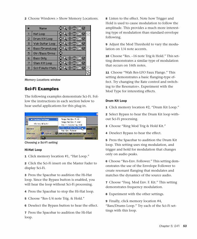
2 Choose Windows > Show Memory Locations.
Sci-Fi Examples
The following examples demonstrate Sci-Fi. Fol-low the instructions in each section below to hear useful applications for this plug-in.
Hi-Hat Loop
1 Click memory location #1, “Hat Loop.”
2 Click the Sci-Fi insert on the Master Fader to display Sci-Fi.
3 Press the Spacebar to audition the Hi-Hat loop. Since the Bypass button is enabled, you will hear the loop without Sci-Fi processing.
4 Press the Spacebar to stop the Hi-Hat loop.
5 Choose “Res-1/4 note Trig. & Hold.”
6 Deselect the Bypass button to hear the effect.
7 Press the Spacebar to audition the Hi-Hat loop.
Memory Locations window
Choosing a Sci-Fi setting
8 Listen to the effect. Note how Trigger and Hold is used to cause modulation to follow the amplitude. This provides a much more interest-ing type of modulation than standard envelope following.
9 Adjust the Mod Threshold to vary the modu-lation on 1/4 note accents.
10 Choose “Res. –16 note Trig & Hold.” This set-ting demonstrates a similar type of modulation that occurs on 16th notes.
11 Choose “Wah Res-LFO Faux Flange.” This setting demonstrates a basic flanging-type ef-fect. Try changing the Rate control and switch-ing to the Resonator+. Experiment with the Mod Type for interesting effects.
Drum Kit Loop
1 Click memory location #2, “Drum Kit Loop.”
2 Select Bypass to hear the Drum Kit loop with-out Sci-Fi processing.
3 Choose “Ring Mod Trig & Hold Kit.”
4 Deselect Bypass to hear the effect.
5 Press the Spacebar to audition the Drum Kit loop. This setting uses ring modulation, and trigger and hold for modulation that changes only on audio peaks.
6 Choose “Res-Env. Follower.” This setting dem-onstrates the use of the Envelope Follower to create resonant flanging that modulates and matches the dynamics of the source audio.
7 Choose “Freq. Mod Env. F. Kit.” This setting demonstrates frequency modulation.
8 Experiment with the other settings.
9 Finally, click memory location #4, “Bass/Drums Loop.” Try each of the Sci-Fi set-tings with this loop.
Chapter 5: D-Fi 53
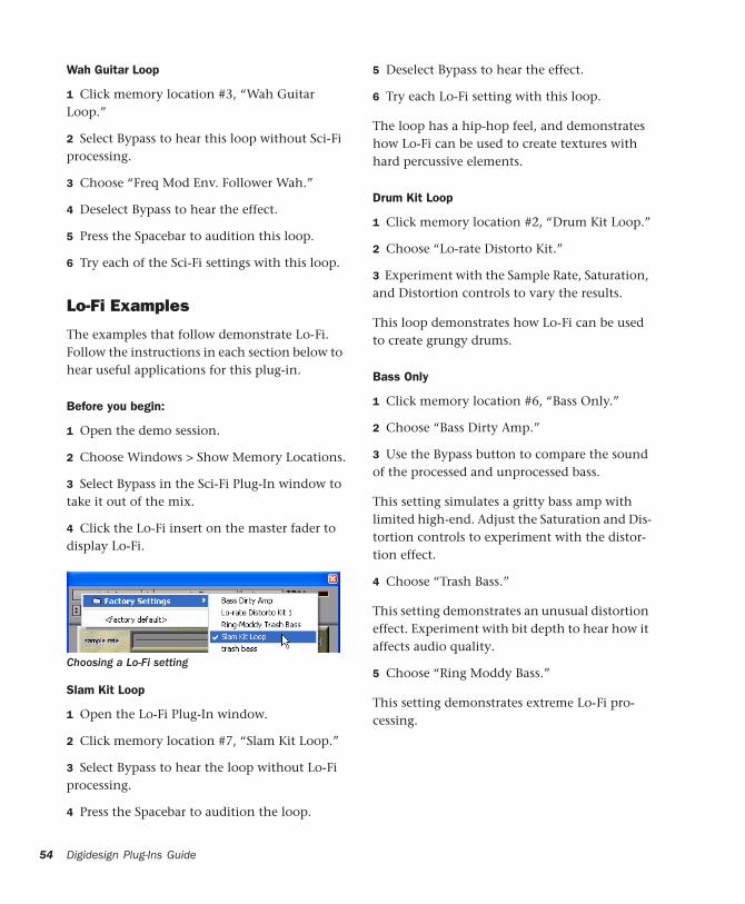
54
Wah Guitar Loop
1 Click memory location #3, “Wah Guitar Loop.”
2 Select Bypass to hear this loop without Sci-Fi processing.
3 Choose “Freq Mod Env. Follower Wah.”
4 Deselect Bypass to hear the effect.
5 Press the Spacebar to audition this loop.
6 Try each of the Sci-Fi settings with this loop.
Lo-Fi Examples
The examples that follow demonstrate Lo-Fi. Follow the instructions in each section below to hear useful applications for this plug-in.
Before you begin:
1 Open the demo session.
2 Choose Windows > Show Memory Locations.
3 Select Bypass in the Sci-Fi Plug-In window to take it out of the mix.
4 Click the Lo-Fi insert on the master fader to display Lo-Fi.
Slam Kit Loop
1 Open the Lo-Fi Plug-In window.
2 Click memory location #7, “Slam Kit Loop.”
3 Select Bypass to hear the loop without Lo-Fi processing.
4 Press the Spacebar to audition the loop.
Choosing a Lo-Fi setting
Digidesign Plug-Ins Guide
5 Deselect Bypass to hear the effect.
6 Try each Lo-Fi setting with this loop.
The loop has a hip-hop feel, and demonstrates how Lo-Fi can be used to create textures with hard percussive elements.
Drum Kit Loop
1 Click memory location #2, “Drum Kit Loop.”
2 Choose “Lo-rate Distorto Kit.”
3 Experiment with the Sample Rate, Saturation, and Distortion controls to vary the results.
This loop demonstrates how Lo-Fi can be used to create grungy drums.
Bass Only
1 Click memory location #6, “Bass Only.”
2 Choose “Bass Dirty Amp.”
3 Use the Bypass button to compare the sound of the processed and unprocessed bass.
This setting simulates a gritty bass amp with limited high-end. Adjust the Saturation and Dis-tortion controls to experiment with the distor-tion effect.
4 Choose “Trash Bass.”
This setting demonstrates an unusual distortion effect. Experiment with bit depth to hear how it affects audio quality.
5 Choose “Ring Moddy Bass.”
This setting demonstrates extreme Lo-Fi pro-cessing.
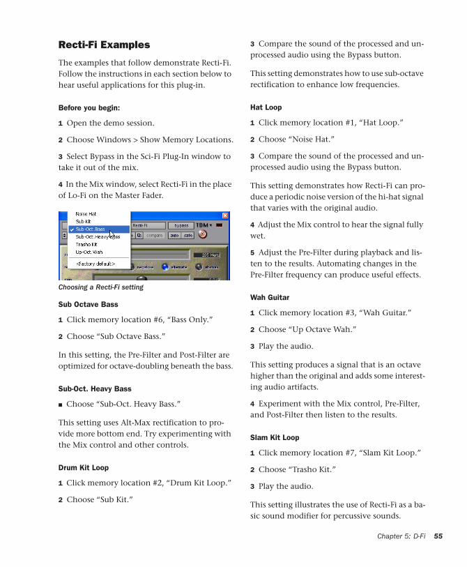
Recti-Fi Examples
The examples that follow demonstrate Recti-Fi. Follow the instructions in each section below to hear useful applications for this plug-in.
Before you begin:
1 Open the demo session.
2 Choose Windows > Show Memory Locations.
3 Select Bypass in the Sci-Fi Plug-In window to take it out of the mix.
4 In the Mix window, select Recti-Fi in the place of Lo-Fi on the Master Fader.
Sub Octave Bass
1 Click memory location #6, “Bass Only.”
2 Choose “Sub Octave Bass.”
In this setting, the Pre-Filter and Post-Filter are optimized for octave-doubling beneath the bass.
Sub-Oct. Heavy Bass
■ Choose “Sub-Oct. Heavy Bass.”
This setting uses Alt-Max rectification to pro-vide more bottom end. Try experimenting with the Mix control and other controls.
Drum Kit Loop
1 Click memory location #2, “Drum Kit Loop.”
2 Choose “Sub Kit.”
Choosing a Recti-Fi setting
3 Compare the sound of the processed and un-processed audio using the Bypass button.
This setting demonstrates how to use sub-octave rectification to enhance low frequencies.
Hat Loop
1 Click memory location #1, “Hat Loop.”
2 Choose “Noise Hat.”
3 Compare the sound of the processed and un-processed audio using the Bypass button.
This setting demonstrates how Recti-Fi can pro-duce a periodic noise version of the hi-hat signal that varies with the original audio.
4 Adjust the Mix control to hear the signal fully wet.
5 Adjust the Pre-Filter during playback and lis-ten to the results. Automating changes in the Pre-Filter frequency can produce useful effects.
Wah Guitar
1 Click memory location #3, “Wah Guitar.”
2 Choose “Up Octave Wah.”
3 Play the audio.
This setting produces a signal that is an octave higher than the original and adds some interest-ing audio artifacts.
4 Experiment with the Mix control, Pre-Filter, and Post-Filter then listen to the results.
Slam Kit Loop
1 Click memory location #7, “Slam Kit Loop.”
2 Choose “Trasho Kit.”
3 Play the audio.
This setting illustrates the use of Recti-Fi as a ba-sic sound modifier for percussive sounds.
Chapter 5: D-Fi 55

56
Digidesign Plug-Ins Guide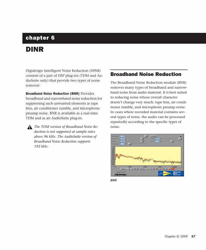
chapter 6
DINR
Digidesign Intelligent Noise Reduction (DINR) consists of a pair of DSP plug-ins (TDM and Au-dioSuite only) that provide two types of noise removal:
Broadband Noise Reduction (BNR) Provides broadband and narrowband noise reduction for suppressing such unwanted elements as tape hiss, air conditioner rumble, and microphone preamp noise. BNR is available as a real-time TDM and as an AudioSuite plug-in.
The TDM version of Broadband Noise Re-duction is not supported at sample rates above 96 kHz. The AudioSuite version of Broadband Noise Reduction supports 192 kHz.
Broadband Noise ReductionThe Broadband Noise Reduction module (BNR) removes many types of broadband and narrow-band noise from audio material. It is best suited to reducing noise whose overall character doesn’t change very much: tape hiss, air condi-tioner rumble, and microphone preamp noise. In cases where recorded material contains sev-eral types of noise, the audio can be processed repeatedly according to the specific types of noise.
BNR
Chapter 6: DINR 57
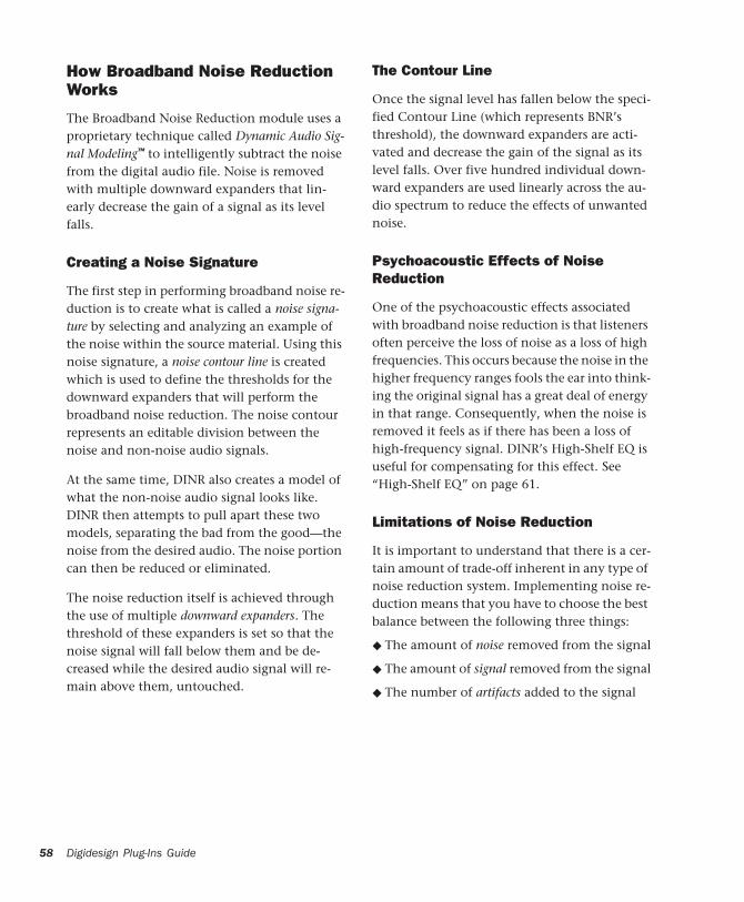
58
How Broadband Noise Reduction Works
The Broadband Noise Reduction module uses a proprietary technique called Dynamic Audio Sig-nal Modeling™ to intelligently subtract the noise from the digital audio file. Noise is removed with multiple downward expanders that lin-early decrease the gain of a signal as its level falls.
Creating a Noise Signature
The first step in performing broadband noise re-duction is to create what is called a noise signa-ture by selecting and analyzing an example of the noise within the source material. Using this noise signature, a noise contour line is created which is used to define the thresholds for the downward expanders that will perform the broadband noise reduction. The noise contour represents an editable division between the noise and non-noise audio signals.
At the same time, DINR also creates a model of what the non-noise audio signal looks like. DINR then attempts to pull apart these two models, separating the bad from the good—the noise from the desired audio. The noise portion can then be reduced or eliminated.
The noise reduction itself is achieved through the use of multiple downward expanders. The threshold of these expanders is set so that the noise signal will fall below them and be de-creased while the desired audio signal will re-main above them, untouched.
Digidesign Plug-Ins Guide
The Contour Line
Once the signal level has fallen below the speci-fied Contour Line (which represents BNR’s threshold), the downward expanders are acti-vated and decrease the gain of the signal as its level falls. Over five hundred individual down-ward expanders are used linearly across the au-dio spectrum to reduce the effects of unwanted noise.
Psychoacoustic Effects of Noise Reduction
One of the psychoacoustic effects associated with broadband noise reduction is that listeners often perceive the loss of noise as a loss of high frequencies. This occurs because the noise in the higher frequency ranges fools the ear into think-ing the original signal has a great deal of energy in that range. Consequently, when the noise is removed it feels as if there has been a loss of high-frequency signal. DINR’s High-Shelf EQ is useful for compensating for this effect. See “High-Shelf EQ” on page 61.
Limitations of Noise Reduction
It is important to understand that there is a cer-tain amount of trade-off inherent in any type of noise reduction system. Implementing noise re-duction means that you have to choose the best balance between the following three things:
◆ The amount of noise removed from the signal
◆ The amount of signal removed from the signal
◆ The number of artifacts added to the signal
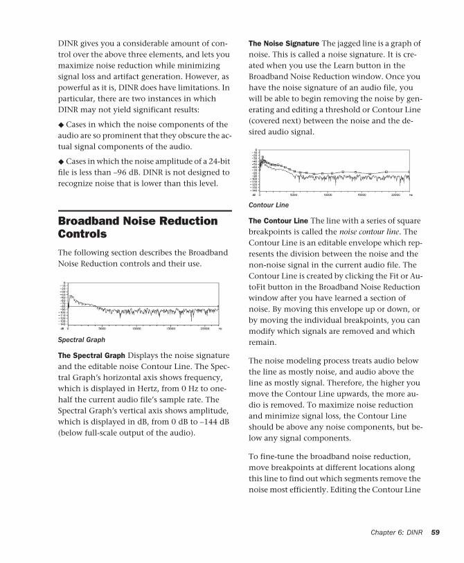
DINR gives you a considerable amount of con-trol over the above three elements, and lets you maximize noise reduction while minimizing signal loss and artifact generation. However, as powerful as it is, DINR does have limitations. In particular, there are two instances in which DINR may not yield significant results:
◆ Cases in which the noise components of the audio are so prominent that they obscure the ac-tual signal components of the audio.
◆ Cases in which the noise amplitude of a 24-bit file is less than –96 dB. DINR is not designed to recognize noise that is lower than this level.
Broadband Noise Reduction ControlsThe following section describes the Broadband Noise Reduction controls and their use.
The Spectral Graph Displays the noise signature and the editable noise Contour Line. The Spec-tral Graph’s horizontal axis shows frequency, which is displayed in Hertz, from 0 Hz to one-half the current audio file’s sample rate. The Spectral Graph’s vertical axis shows amplitude, which is displayed in dB, from 0 dB to –144 dB (below full-scale output of the audio).
Spectral Graph
The Noise Signature The jagged line is a graph of noise. This is called a noise signature. It is cre-ated when you use the Learn button in the Broadband Noise Reduction window. Once you have the noise signature of an audio file, you will be able to begin removing the noise by gen-erating and editing a threshold or Contour Line (covered next) between the noise and the de-sired audio signal.
The Contour Line The line with a series of square breakpoints is called the noise contour line. The Contour Line is an editable envelope which rep-resents the division between the noise and the non-noise signal in the current audio file. The Contour Line is created by clicking the Fit or Au-toFit button in the Broadband Noise Reduction window after you have learned a section of noise. By moving this envelope up or down, or by moving the individual breakpoints, you can modify which signals are removed and which remain.
The noise modeling process treats audio below the line as mostly noise, and audio above the line as mostly signal. Therefore, the higher you move the Contour Line upwards, the more au-dio is removed. To maximize noise reduction and minimize signal loss, the Contour Line should be above any noise components, but be-low any signal components.
To fine-tune the broadband noise reduction, move breakpoints at different locations along this line to find out which segments remove the noise most efficiently. Editing the Contour Line
Contour Line
Chapter 6: DINR 59
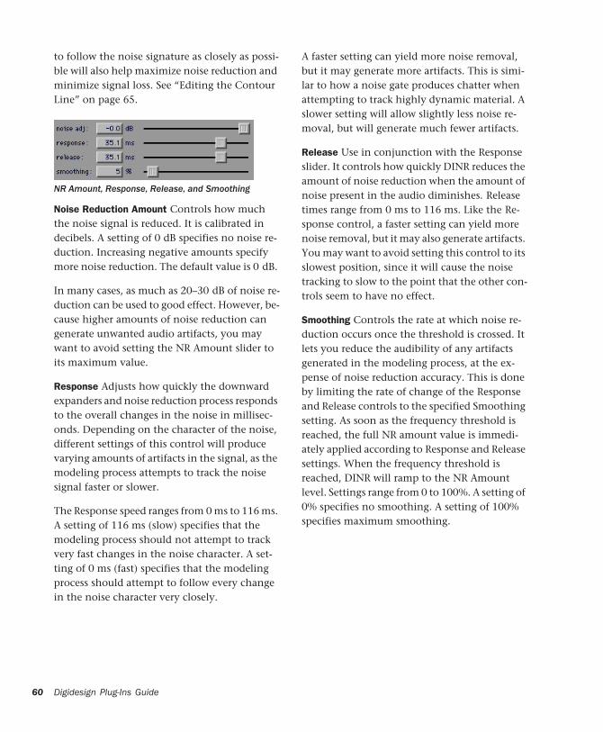
60
to follow the noise signature as closely as possi-ble will also help maximize noise reduction and minimize signal loss. See “Editing the Contour Line” on page 65.
Noise Reduction Amount Controls how much the noise signal is reduced. It is calibrated in decibels. A setting of 0 dB specifies no noise re-duction. Increasing negative amounts specify more noise reduction. The default value is 0 dB.
In many cases, as much as 20–30 dB of noise re-duction can be used to good effect. However, be-cause higher amounts of noise reduction can generate unwanted audio artifacts, you may want to avoid setting the NR Amount slider to its maximum value.
Response Adjusts how quickly the downward expanders and noise reduction process responds to the overall changes in the noise in millisec-onds. Depending on the character of the noise, different settings of this control will produce varying amounts of artifacts in the signal, as the modeling process attempts to track the noise signal faster or slower.
The Response speed ranges from 0 ms to 116 ms. A setting of 116 ms (slow) specifies that the modeling process should not attempt to track very fast changes in the noise character. A set-ting of 0 ms (fast) specifies that the modeling process should attempt to follow every change in the noise character very closely.
NR Amount, Response, Release, and Smoothing
Digidesign Plug-Ins Guide
A faster setting can yield more noise removal, but it may generate more artifacts. This is simi-lar to how a noise gate produces chatter when attempting to track highly dynamic material. A slower setting will allow slightly less noise re-moval, but will generate much fewer artifacts.
Release Use in conjunction with the Response slider. It controls how quickly DINR reduces the amount of noise reduction when the amount of noise present in the audio diminishes. Release times range from 0 ms to 116 ms. Like the Re-sponse control, a faster setting can yield more noise removal, but it may also generate artifacts. You may want to avoid setting this control to its slowest position, since it will cause the noise tracking to slow to the point that the other con-trols seem to have no effect.
Smoothing Controls the rate at which noise re-duction occurs once the threshold is crossed. It lets you reduce the audibility of any artifacts generated in the modeling process, at the ex-pense of noise reduction accuracy. This is done by limiting the rate of change of the Response and Release controls to the specified Smoothing setting. As soon as the frequency threshold is reached, the full NR amount value is immedi-ately applied according to Response and Release settings. When the frequency threshold is reached, DINR will ramp to the NR Amount level. Settings range from 0 to 100%. A setting of 0% specifies no smoothing. A setting of 100% specifies maximum smoothing.
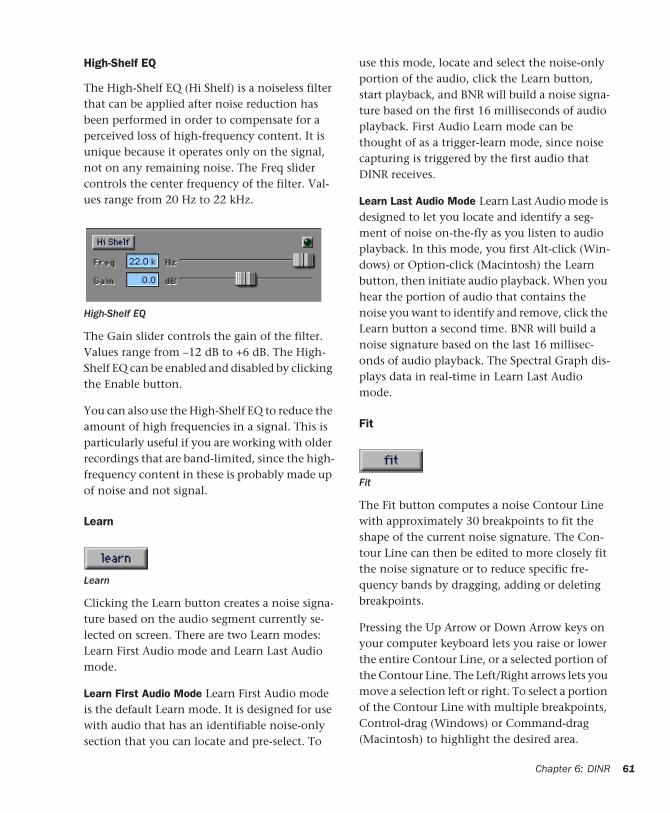
High-Shelf EQ
The High-Shelf EQ (Hi Shelf) is a noiseless filter that can be applied after noise reduction has been performed in order to compensate for a perceived loss of high-frequency content. It is unique because it operates only on the signal, not on any remaining noise. The Freq slider controls the center frequency of the filter. Val-ues range from 20 Hz to 22 kHz.
The Gain slider controls the gain of the filter. Values range from –12 dB to +6 dB. The High-Shelf EQ can be enabled and disabled by clicking the Enable button.
You can also use the High-Shelf EQ to reduce the amount of high frequencies in a signal. This is particularly useful if you are working with older recordings that are band-limited, since the high-frequency content in these is probably made up of noise and not signal.
Learn
Clicking the Learn button creates a noise signa-ture based on the audio segment currently se-lected on screen. There are two Learn modes: Learn First Audio mode and Learn Last Audio mode.
Learn First Audio Mode Learn First Audio mode is the default Learn mode. It is designed for use with audio that has an identifiable noise-only section that you can locate and pre-select. To
High-Shelf EQ
Learn
use this mode, locate and select the noise-only portion of the audio, click the Learn button, start playback, and BNR will build a noise signa-ture based on the first 16 milliseconds of audio playback. First Audio Learn mode can be thought of as a trigger-learn mode, since noise capturing is triggered by the first audio that DINR receives.
Learn Last Audio Mode Learn Last Audio mode is designed to let you locate and identify a seg-ment of noise on-the-fly as you listen to audio playback. In this mode, you first Alt-click (Win-dows) or Option-click (Macintosh) the Learn button, then initiate audio playback. When you hear the portion of audio that contains the noise you want to identify and remove, click the Learn button a second time. BNR will build a noise signature based on the last 16 millisec-onds of audio playback. The Spectral Graph dis-plays data in real-time in Learn Last Audio mode.
Fit
The Fit button computes a noise Contour Line with approximately 30 breakpoints to fit the shape of the current noise signature. The Con-tour Line can then be edited to more closely fit the noise signature or to reduce specific fre-quency bands by dragging, adding or deleting breakpoints.
Pressing the Up Arrow or Down Arrow keys on your computer keyboard lets you raise or lower the entire Contour Line, or a selected portion of the Contour Line. The Left/Right arrows lets you move a selection left or right. To select a portion of the Contour Line with multiple breakpoints, Control-drag (Windows) or Command-drag (Macintosh) to highlight the desired area.
Fit
Chapter 6: DINR 61
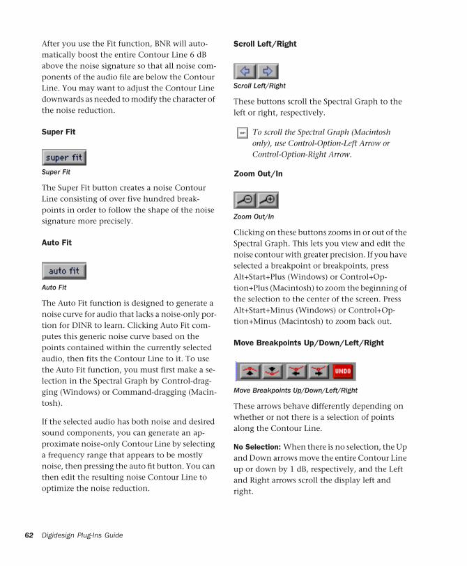
62
After you use the Fit function, BNR will auto-matically boost the entire Contour Line 6 dB above the noise signature so that all noise com-ponents of the audio file are below the Contour Line. You may want to adjust the Contour Line downwards as needed to modify the character of the noise reduction.
Super Fit
The Super Fit button creates a noise Contour Line consisting of over five hundred break-points in order to follow the shape of the noise signature more precisely.
Auto Fit
The Auto Fit function is designed to generate a noise curve for audio that lacks a noise-only por-tion for DINR to learn. Clicking Auto Fit com-putes this generic noise curve based on the points contained within the currently selected audio, then fits the Contour Line to it. To use the Auto Fit function, you must first make a se-lection in the Spectral Graph by Control-drag-ging (Windows) or Command-dragging (Macin-tosh).
If the selected audio has both noise and desired sound components, you can generate an ap-proximate noise-only Contour Line by selecting a frequency range that appears to be mostly noise, then pressing the auto fit button. You can then edit the resulting noise Contour Line to optimize the noise reduction.
Super Fit
Auto Fit
Digidesign Plug-Ins Guide
Scroll Left/Right
These buttons scroll the Spectral Graph to the left or right, respectively.
Zoom Out/In
Clicking on these buttons zooms in or out of the Spectral Graph. This lets you view and edit the noise contour with greater precision. If you have selected a breakpoint or breakpoints, press Alt+Start+Plus (Windows) or Control+Op-tion+Plus (Macintosh) to zoom the beginning of the selection to the center of the screen. Press Alt+Start+Minus (Windows) or Control+Op-tion+Minus (Macintosh) to zoom back out.
Move Breakpoints Up/Down/Left/Right
These arrows behave differently depending on whether or not there is a selection of points along the Contour Line.
No Selection: When there is no selection, the Up and Down arrows move the entire Contour Line up or down by 1 dB, respectively, and the Left and Right arrows scroll the display left and right.
Scroll Left/Right
To scroll the Spectral Graph (Macintosh only), use Control-Option-Left Arrow or Control-Option-Right Arrow.
Zoom Out/In
Move Breakpoints Up/Down/Left/Right
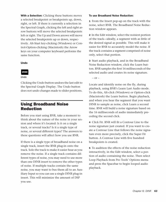
With a Selection: Clicking these buttons moves a selected breakpoint or breakpoints up, down, right, or left. If there is currently a selection in the Spectral Graph, clicking the left and right ar-row buttons will move the selected breakpoints left or right. The Up and Down arrows will move the selected breakpoints up or down, respec-tively. Alt-Start key-clicking (Windows) or Con-trol-Option-clicking (Macintosh) the Arrow keys on your computer keyboard performs the same function.
Undo
Clicking the Undo button undoes the last edit to the Spectral Graph Display. The Undo button does not undo changes made to slider positions.
Using Broadband Noise ReductionBefore you start using BNR, take a moment to think about the nature of the noise in your ses-sion and where it’s located: Is it on a single track, or several tracks? Is it a single type of noise, or several different types? The answers to these questions will affect how you use BNR.
If there is a single type of broadband noise on a single track, insert the BNR plug-in onto the track. Solo the track to make it easier hear as you remove the noise. If a single track contains dif-ferent types of noise, you may need to use more than one DINR insert to remove the other types of noise. If multiple tracks contain the same noise, you may want to bus them all to an Aux-iliary Input so you can use a single DINR plug-in insert. This will minimize the amount of DSP you use.
Undo
To use Broadband Noise Reduction:
1 From the Insert pop-up on the track with the noise, select BNR. The Broadband Noise Reduc-tion window appears.
2 In the Edit window, select the noisiest portion of the track—ideally, a segment with as little of the desired signal as possible. This will make it easier for BNR to accurately model the noise. If the track contains a segment comprised of noise only, select that portion.
3 Start audio playback, and in the Broadband Noise Reduction window, click the Learn but-ton. BNR samples the first 16 milliseconds of the selected audio and creates its noise signature.
– or –
Locate and identify noise on the fly, during playback, using BNR’s Learn Last Audio mode. To do this, Alt-click (Windows) or Option-click (Macintosh) the Learn button. Begin playback, and when you hear the segment that you want DINR to sample as noise, click Learn a second time. BNR will build a noise signature based on the 16 milliseconds of audio immediately pre-ceding the second click.
4 Click Fit. BNR will fit a Contour Line to the noise signature just created. If you want to cre-ate a Contour Line that follows the noise signa-ture even more precisely, click the Super Fit button. A Contour Line with five hundred breakpoints is created.
5 To audition the effects of the noise reduction interactively, in the Edit window, select a por-tion of audio containing the noise. Then select Loop Playback from Pro Tools’ Options menu and press the Spacebar to begin looped audio playback.
Chapter 6: DINR 63
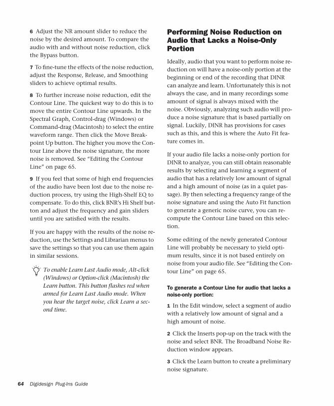
64
6 Adjust the NR amount slider to reduce the noise by the desired amount. To compare the audio with and without noise reduction, click the Bypass button.
7 To fine-tune the effects of the noise reduction, adjust the Response, Release, and Smoothing sliders to achieve optimal results.
8 To further increase noise reduction, edit the Contour Line. The quickest way to do this is to move the entire Contour Line upwards. In the Spectral Graph, Control-drag (Windows) or Command-drag (Macintosh) to select the entire waveform range. Then click the Move Break-point Up button. The higher you move the Con-tour Line above the noise signature, the more noise is removed. See “Editing the Contour Line” on page 65.
9 If you feel that some of high end frequencies of the audio have been lost due to the noise re-duction process, try using the High-Shelf EQ to compensate. To do this, click BNR’s Hi Shelf but-ton and adjust the frequency and gain sliders until you are satisfied with the results.
If you are happy with the results of the noise re-duction, use the Settings and Librarian menus to save the settings so that you can use them again in similar sessions.
To enable Learn Last Audio mode, Alt-click (Windows) or Option-click (Macintosh) the Learn button. This button flashes red when armed for Learn Last Audio mode. When you hear the target noise, click Learn a sec-ond time.
Digidesign Plug-Ins Guide
Performing Noise Reduction on Audio that Lacks a Noise-Only Portion
Ideally, audio that you want to perform noise re-duction on will have a noise-only portion at the beginning or end of the recording that DINR can analyze and learn. Unfortunately this is not always the case, and in many recordings some amount of signal is always mixed with the noise. Obviously, analyzing such audio will pro-duce a noise signature that is based partially on signal. Luckily, DINR has provisions for cases such as this, and this is where the Auto Fit fea-ture comes in.
If your audio file lacks a noise-only portion for DINR to analyze, you can still obtain reasonable results by selecting and learning a segment of audio that has a relatively low amount of signal and a high amount of noise (as in a quiet pas-sage). By then selecting a frequency range of the noise signature and using the Auto Fit function to generate a generic noise curve, you can re-compute the Contour Line based on this selec-tion.
Some editing of the newly generated Contour Line will probably be necessary to yield opti-mum results, since it is not based entirely on noise from your audio file. See “Editing the Con-tour Line” on page 65.
To generate a Contour Line for audio that lacks a noise-only portion:
1 In the Edit window, select a segment of audio with a relatively low amount of signal and a high amount of noise.
2 Click the Inserts pop-up on the track with the noise and select BNR. The Broadband Noise Re-duction window appears.
3 Click the Learn button to create a preliminary noise signature.
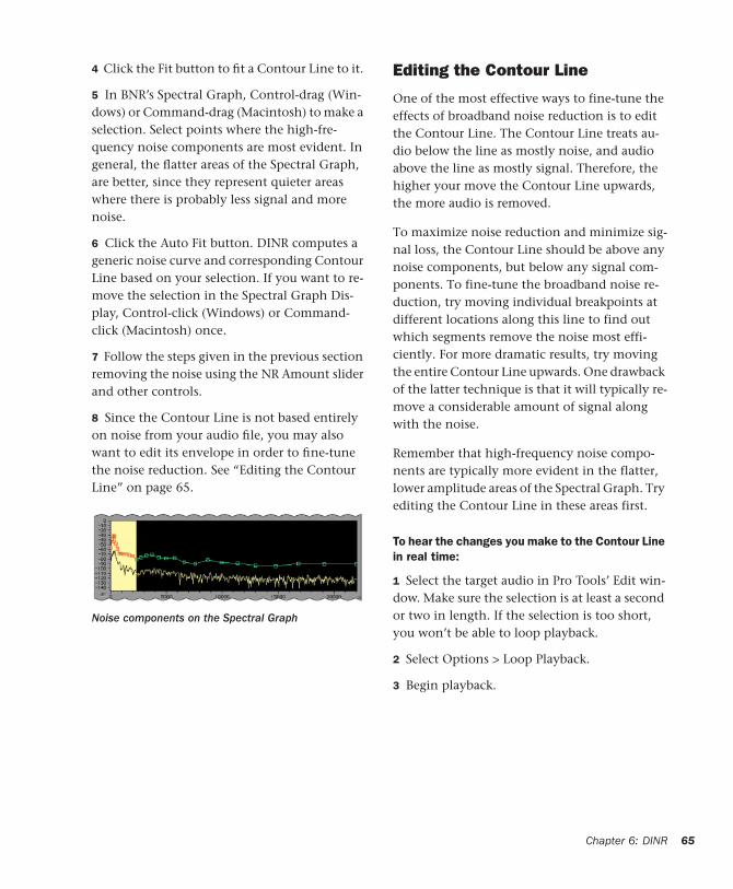
4 Click the Fit button to fit a Contour Line to it.
5 In BNR’s Spectral Graph, Control-drag (Win-dows) or Command-drag (Macintosh) to make a selection. Select points where the high-fre-quency noise components are most evident. In general, the flatter areas of the Spectral Graph, are better, since they represent quieter areas where there is probably less signal and more noise.
6 Click the Auto Fit button. DINR computes a generic noise curve and corresponding Contour Line based on your selection. If you want to re-move the selection in the Spectral Graph Dis-play, Control-click (Windows) or Command-click (Macintosh) once.
7 Follow the steps given in the previous section removing the noise using the NR Amount slider and other controls.
8 Since the Contour Line is not based entirely on noise from your audio file, you may also want to edit its envelope in order to fine-tune the noise reduction. See “Editing the Contour Line” on page 65.
Noise components on the Spectral Graph
Editing the Contour Line
One of the most effective ways to fine-tune the effects of broadband noise reduction is to edit the Contour Line. The Contour Line treats au-dio below the line as mostly noise, and audio above the line as mostly signal. Therefore, the higher your move the Contour Line upwards, the more audio is removed.
To maximize noise reduction and minimize sig-nal loss, the Contour Line should be above any noise components, but below any signal com-ponents. To fine-tune the broadband noise re-duction, try moving individual breakpoints at different locations along this line to find out which segments remove the noise most effi-ciently. For more dramatic results, try moving the entire Contour Line upwards. One drawback of the latter technique is that it will typically re-move a considerable amount of signal along with the noise.
Remember that high-frequency noise compo-nents are typically more evident in the flatter, lower amplitude areas of the Spectral Graph. Try editing the Contour Line in these areas first.
To hear the changes you make to the Contour Line in real time:
1 Select the target audio in Pro Tools’ Edit win-dow. Make sure the selection is at least a second or two in length. If the selection is too short, you won’t be able to loop playback.
2 Select Options > Loop Playback.
3 Begin playback.
Chapter 6: DINR 65
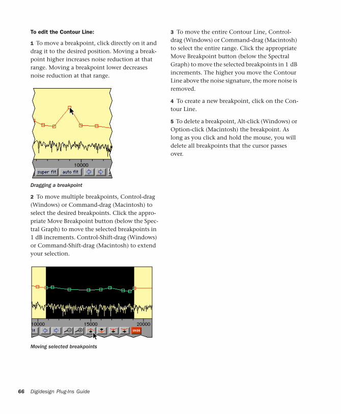
66
To edit the Contour Line:
1 To move a breakpoint, click directly on it and drag it to the desired position. Moving a break-point higher increases noise reduction at that range. Moving a breakpoint lower decreases noise reduction at that range.
2 To move multiple breakpoints, Control-drag (Windows) or Command-drag (Macintosh) to select the desired breakpoints. Click the appro-priate Move Breakpoint button (below the Spec-tral Graph) to move the selected breakpoints in 1 dB increments. Control-Shift-drag (Windows) or Command-Shift-drag (Macintosh) to extend your selection.
Dragging a breakpoint
Moving selected breakpoints
Digidesign Plug-Ins Guide
3 To move the entire Contour Line, Control-drag (Windows) or Command-drag (Macintosh) to select the entire range. Click the appropriate Move Breakpoint button (below the Spectral Graph) to move the selected breakpoints in 1 dB increments. The higher you move the Contour Line above the noise signature, the more noise is removed.
4 To create a new breakpoint, click on the Con-tour Line.
5 To delete a breakpoint, Alt-click (Windows) or Option-click (Macintosh) the breakpoint. As long as you click and hold the mouse, you will delete all breakpoints that the cursor passes over.
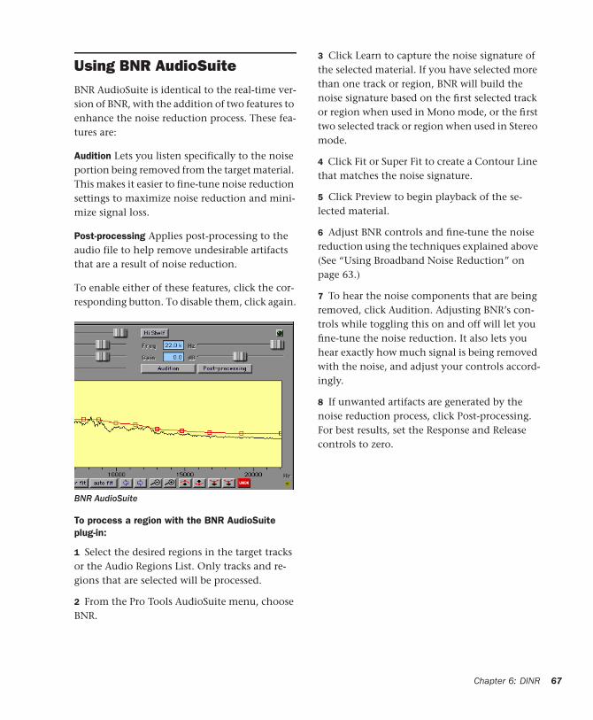
Using BNR AudioSuiteBNR AudioSuite is identical to the real-time ver-sion of BNR, with the addition of two features to enhance the noise reduction process. These fea-tures are:
Audition Lets you listen specifically to the noise portion being removed from the target material. This makes it easier to fine-tune noise reduction settings to maximize noise reduction and mini-mize signal loss.
Post-processing Applies post-processing to the audio file to help remove undesirable artifacts that are a result of noise reduction.
To enable either of these features, click the cor-responding button. To disable them, click again.
To process a region with the BNR AudioSuite plug-in:
1 Select the desired regions in the target tracks or the Audio Regions List. Only tracks and re-gions that are selected will be processed.
2 From the Pro Tools AudioSuite menu, choose BNR.
BNR AudioSuite
3 Click Learn to capture the noise signature of the selected material. If you have selected more than one track or region, BNR will build the noise signature based on the first selected track or region when used in Mono mode, or the first two selected track or region when used in Stereo mode.
4 Click Fit or Super Fit to create a Contour Line that matches the noise signature.
5 Click Preview to begin playback of the se-lected material.
6 Adjust BNR controls and fine-tune the noise reduction using the techniques explained above (See “Using Broadband Noise Reduction” on page 63.)
7 To hear the noise components that are being removed, click Audition. Adjusting BNR’s con-trols while toggling this on and off will let you fine-tune the noise reduction. It also lets you hear exactly how much signal is being removed with the noise, and adjust your controls accord-ingly.
8 If unwanted artifacts are generated by the noise reduction process, click Post-processing. For best results, set the Response and Release controls to zero.
Chapter 6: DINR 67
68
To begin AudioSuite processing:
1 Adjust the AudioSuite File controls. These set-tings will determine how the file is processed and what effect the processing will have on the original regions. Here are some guidelines:
◆ To process the selected region only in the track in which it appears, choose Playlist from the Selection Reference pop-up.
– or –
To process the selected region in the Audio Re-gions List only, choose Region List from this pop-up.
◆ To process and update every occurrence of the selected region throughout your session, enable the Use In Playlist button (and also choose Re-gion List from the Selection Reference pop-up).
– or –
If you do not want to update every occurrence of the selected region, disable the Use In Playlist button.
◆ If you have selected multiple regions for pro-cessing and want to create a new file that con-nects and consolidates all of these regions together, choose Create Continuous File from the File mode pop-up menu.
2 From the Destination Track pop-up, choose the destination for the replacement audio.
3 Click Process.
BNR AudioSuite does not allow destructive processing, so the Overwrite Files option is not available in the File mode pop-up menu.
Digidesign Plug-Ins Guide
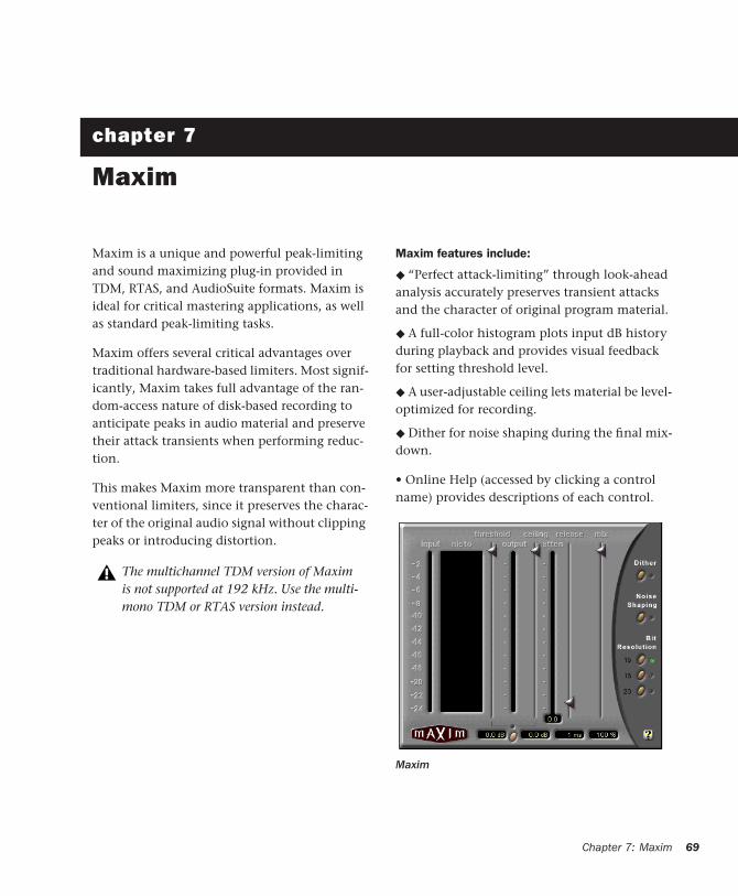
chapter 7
Maxim
Maxim is a unique and powerful peak-limiting and sound maximizing plug-in provided in TDM, RTAS, and AudioSuite formats. Maxim is ideal for critical mastering applications, as well as standard peak-limiting tasks.
Maxim offers several critical advantages over traditional hardware-based limiters. Most signif-icantly, Maxim takes full advantage of the ran-dom-access nature of disk-based recording to anticipate peaks in audio material and preserve their attack transients when performing reduc-tion.
This makes Maxim more transparent than con-ventional limiters, since it preserves the charac-ter of the original audio signal without clipping peaks or introducing distortion.
The multichannel TDM version of Maxim is not supported at 192 kHz. Use the multi-mono TDM or RTAS version instead.
Maxim features include:
◆ “Perfect attack-limiting” through look-ahead analysis accurately preserves transient attacks and the character of original program material.
◆ A full-color histogram plots input dB history during playback and provides visual feedback for setting threshold level.
◆ A user-adjustable ceiling lets material be level-optimized for recording.
◆ Dither for noise shaping during the final mix-down.
• Online Help (accessed by clicking a control name) provides descriptions of each control.
Maxim
Chapter 7: Maxim 69
70
About Peak LimitingPeak limiting is an important element of audio production. It is the process of preventing signal peaks in audio material from clipping by limit-ing their dynamic range to an absolute, user-se-lectable ceiling and not letting them exceed this ceiling.
Limiters let you select a threshold in decibels. If an audio signal peak exceeds this threshold, gain reduction is applied, and the audio is atten-uated by a user-selectable amount.
Limiting has two main uses in the audio produc-tion cycle:
• Adjusting the dynamic range of an entire final mixdown for premastering purposes
• Adjusting the dynamic range of individual in-struments for creative purposes
Limiting a Mixdown
The purpose of applying limiting during final mixdown is to flatten any large peaks remaining in the audio material to have a higher average signal level in the final mix. By flattening peaks that would otherwise clip, it is possible to in-crease the overall level of the rest of the mix. This results in higher average audio levels, po-tentially better signal to noise ratio, and a smoother mix.
Digidesign Plug-Ins Guide
Limiting Individual Instruments
The primary purpose of applying limiting to in-dividual instruments is to alter their dynamic range in subtle or not-so-subtle ways. A com-mon application of this type of limiting is to modify the character of drums. Many engineers do this by applying heavy limiting to flatten the snap of the attack portion of a drum hit. By ad-justing the release time of the limiter it is possi-ble to bring up room tone contained in the de-cay portion of the drum sound.
In some cases, this type of limiting can actually change a drum’s character from a very dry sound to a relatively wet sound if there is enough room tone present. This method is not without its drawbacks, however, since it can also bring noise levels up in the source audio if present.
How Maxim Differs From Conventional Limiters
Maxim is superior to conventional limiters in several ways. Unlike traditional limiters, Maxim has the ability to anticipate signal peaks and re-spond instantaneously with a true zero attack time.
Maxim does this by buffering audio with a 1024-sample delay while looking ahead and analyz-ing audio material on disk before applying lim-iting. Maxim can then instantly apply limiting before a peak builds up. The result is extremely transparent limiting that faithfully preserves the attack transients and retains the overall charac-ter of the original unprocessed signal.
In addition, Maxim provides a histogram, that displays the distribution of waveform peaks in the audio signal. This provides a convenient vi-sual reference for comparing the density of waveform peaks at different decibel levels and choosing how much limiting to apply to the material.
The TDM version of Maxim introduces 1028 samples of delay at 48 kHz into any processed signal. The RTAS version of Maxim introduces 1024 samples of delay. These delays will increase proportionally at higher sample rates. To preserve phase syn-chronicity between multiple audio sources when Maxim is only applied to one of these sources, use Delay Compensation, or the DigiRack Time Adjuster plug-in to compen-sate.
Maxim Controls and MetersMaxim features the following controls and indi-cators:
Input Level Meter
This meter displays the amplitude of input sig-nals prior to limiting. Unlike conventional meters, Maxim’s input meter displays the top 24 dB of dynamic range of audio signals, which is where limiting is typically performed. This provides you with much greater metering reso-lution within this range so that you can work with greater precision.
Histogram
The histogram displays the distribution of wave-form peaks in the audio signal. This graph is based on audio playback. If you select and play a short loop, the histogram is based on that data. If you select and play a longer section, the histo-gram is based on that. Maxim holds peak data until you click the histogram to clear it.
The histogram provides a visual reference for comparing the density of waveform peaks at dif-ferent decibel levels. You can then base limiting decisions on this data.
The X axis of the histogram shows the number of waveform peaks occurring at specific dB lev-els. The Y axis shows the specific dB level at which these peaks occur. The more waveform peaks that occur at a specific dB level, the longer the X-axis line. If there appears to be a pro-nounced spike at a certain dB level (4 dB for ex-ample), it means that there are a relatively large number of waveform peaks occurring at that level. You can then use this information to de-cide how much limiting to apply to the signal.
Chapter 7: Maxim 71
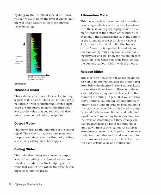
72
By dragging the Threshold slider downwards, you can visually adjust the level at which limit-ing will occur. Maxim displays the affected range in orange.
Threshold Slider
This slider sets the threshold level for limiting. Signals that exceed this level will be limited. Sig-nals below it will be unaffected. Limited signal peaks are attenuated to match the threshold level, so the value that you set here will deter-mine the amount of reduction applied.
Output Meter
This meter displays the amplitude of the output signal. The value that appears here represents the processed signal after the threshold, ceiling, and mixing settings have been applied.
Ceiling Slider
This slider determines the maximum output level. After limiting is performed you can use this slider to adjust the final output gain. The value that you set here will be the absolute ceil-ing level for limited peaks.
Histogram
dB level of waveformpeaks
density of waveformpeaks at each level
Digidesign Plug-Ins Guide
Attenuation Meter
This meter displays the amount of gain reduc-tion being applied over the course of playback, with the maximum peak displayed in the nu-meric readout at the bottom of the meter. For example, if the numerical display at the bottom of the Attenuation meter displays a value of 4 dB, it means that 4 dB of limiting has oc-curred. Since this is a peak-hold readout, you can temporarily walk away from a session dur-ing playback and still know the maximum gain reduction value when you come back. To clear the numeric readout, click it with the mouse.
Release Slider
This slider sets how long it takes for Maxim to ease off of its attenuation after the input signal drops below the threshold level. Because Maxim has an attack time of zero milliseconds, the re-lease slider has a very noticeable effect on the character of limiting. In general, if you are using heavy limiting, you should use proportionally longer release times in order to avoid pumping that may occur when Maxim is forced to jump back and forth between limited and unlimited signal levels. Lengthening the release time has the effect of smoothing out these changes in level by introducing a lag in the ramp-up or ramp-down time of attenuation. Use short re-lease times on material with peaks that are rela-tively few in number and that do not occur in close proximity to each other. The Release con-trol has a default value of 1 millisecond.
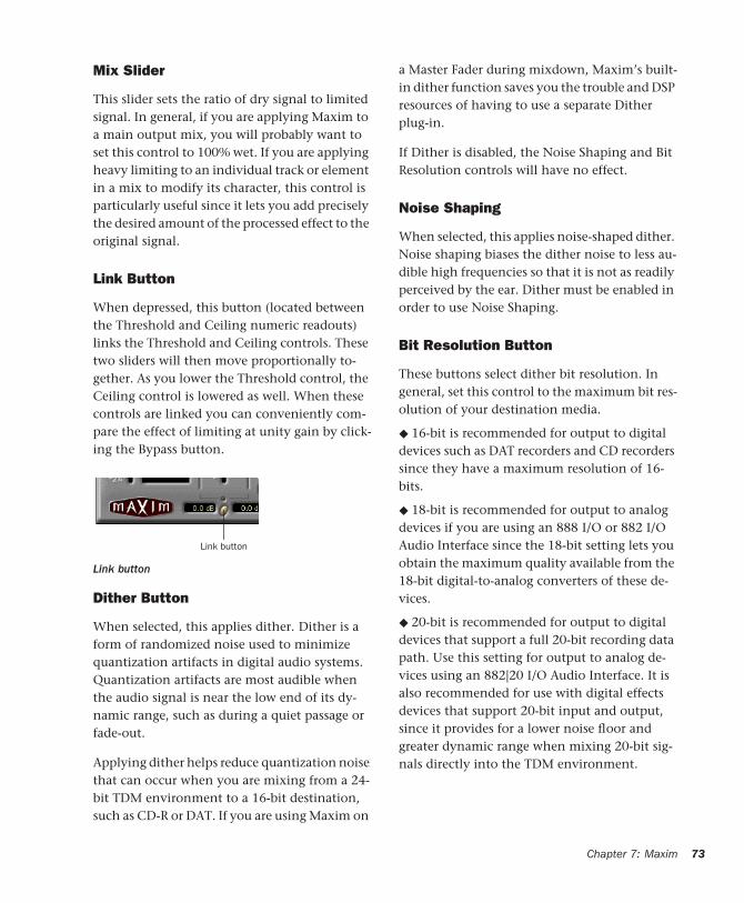
Mix Slider
This slider sets the ratio of dry signal to limited signal. In general, if you are applying Maxim to a main output mix, you will probably want to set this control to 100% wet. If you are applying heavy limiting to an individual track or element in a mix to modify its character, this control is particularly useful since it lets you add precisely the desired amount of the processed effect to the original signal.
Link Button
When depressed, this button (located between the Threshold and Ceiling numeric readouts) links the Threshold and Ceiling controls. These two sliders will then move proportionally to-gether. As you lower the Threshold control, the Ceiling control is lowered as well. When these controls are linked you can conveniently com-pare the effect of limiting at unity gain by click-ing the Bypass button.
Dither Button
When selected, this applies dither. Dither is a form of randomized noise used to minimize quantization artifacts in digital audio systems. Quantization artifacts are most audible when the audio signal is near the low end of its dy-namic range, such as during a quiet passage or fade-out.
Applying dither helps reduce quantization noise that can occur when you are mixing from a 24-bit TDM environment to a 16-bit destination, such as CD-R or DAT. If you are using Maxim on
Link button
Link button
a Master Fader during mixdown, Maxim’s built-in dither function saves you the trouble and DSP resources of having to use a separate Dither plug-in.
If Dither is disabled, the Noise Shaping and Bit Resolution controls will have no effect.
Noise Shaping
When selected, this applies noise-shaped dither. Noise shaping biases the dither noise to less au-dible high frequencies so that it is not as readily perceived by the ear. Dither must be enabled in order to use Noise Shaping.
Bit Resolution Button
These buttons select dither bit resolution. In general, set this control to the maximum bit res-olution of your destination media.
◆ 16-bit is recommended for output to digital devices such as DAT recorders and CD recorders since they have a maximum resolution of 16-bits.
◆ 18-bit is recommended for output to analog devices if you are using an 888 I/O or 882 I/O Audio Interface since the 18-bit setting lets you obtain the maximum quality available from the 18-bit digital-to-analog converters of these de-vices.
◆ 20-bit is recommended for output to digital devices that support a full 20-bit recording data path. Use this setting for output to analog de-vices using an 882|20 I/O Audio Interface. It is also recommended for use with digital effects devices that support 20-bit input and output, since it provides for a lower noise floor and greater dynamic range when mixing 20-bit sig-nals directly into the TDM environment.
Chapter 7: Maxim 73

74
Using MaximFollowing are suggestions for using Maxim most effectively.
To use Maxim:
1 Insert Maxim on the desired track.
2 Select the portion of the track containing the most prominent audio peaks.
3 Loop playback and look at the data displayed by the histogram and attenuator meter.
4 Select the Link button to link the Threshold and Ceiling controls. You can then adjust these controls together proportionally and, using the Bypass button, compare the audio with and without limiting.
5 Adjust the Threshold downwards until you hear and see limiting occur, then bring the Threshold back up slightly until you have roughly the amount of limiting you want.
6 Periodically click and clear the attenuation meter to check attenuation. In general, applying 2 dB to 4 dB of attenuation to occasional peaks in pop-oriented material is appropriate.
7 Use the Bypass button to compare the pro-cessed and unprocessed sound and to check if the results are acceptable.
8 Avoid pumping effects with heavier limiting by setting the Release slider to longer values.
9 When you get the effect you want, deselect the Link button and raise the output level with the Ceiling slider to maximize signal levels with-out clipping.
Digidesign Plug-Ins Guide
In general, a value of 0.5 dB or so is a good max-imum ceiling. Don’t set the ceiling to zero, since the digital-to-analog convertors on some DATs and CD players will clip at or slightly below zero.
Maxim and Mastering
If you intend to deliver audio material as a 24-bit audio file on disk for professional mastering, be aware that many mastering engineers prefer material delivered without dither or level opti-mization.
Mastering engineers typically want to receive audio material as undisturbed as possible in or-der to have leeway to adjust the level of the ma-terial relative to other material on a CD. In such cases, it is advisable to apply only the limiting that you find creatively appropriate—adding a little punch to certain instruments in the mix, for example.
However, if you intend to output the material to DAT or CD-R, use appropriate limiting and add dither. Doing so will optimize the dynamic range and preserve the activity of the lower, or least significant bits in the audio signal, smoothly dithering them into the 16-bit output.
If you are using Maxim on an output mix that will be faded out, enable the dithering options you want to improve the signal per-formance of the material as it fades to lower amplitudes.
chapter 8
Bruno and Reso
Bruno and Reso are a pair of TDM plug-ins that process audio using a sound generation tech-nique known as cross-synthesis.
Cross-synthesis generates complex sound tex-tures by using an audio track as a tone source then applying a variety of synthesizer-type ef-fects to that tone source.
Bruno and Reso each use a different sound gen-eration method:
◆ Bruno uses time-slicing, a technique whereby timbres are extracted from the source audio dur-ing playback and crossfaded together. This crossfading between signals can create a rhyth-mic pulse in the sound as the timbre changes.
◆ Reso uses a resonator, which adds harmonic overtones to the source audio through a short signal delay line with a feedback loop.
In both cases, the processed sound can then be played in real time or sequenced using the MIDI recording and playback capabilities of Pro Tools.
Maximum Voices with HD Accel Card
Bruno and Reso on Pro Tools|HD systems equipped with an HD Accel card offer up to 62 voices of polyphony at the maximum voice set-ting (at 44.1 kHz and 48 kHz).
Bruno features include:
• Time-slice tone generation with adjustable crossfade
• Polyphony: Up to 62 voices of polyphony (on Pro Tools|HD Accel systems)
• Multi-voice detuning
• Editable ADSR envelope generator
• Portamento
• Velocity-sensitive gain and detuning
• Time-slice switching using envelope trig-gering or MIDI beat clock
• Voice-stacking
• Side-chain input for control using an exter-nal audio source
• Supports sample rates up to 192 kHz
• Online help
Chapter 8: Bruno and Reso 75
76
Reso features include:
• Harmonic resonance generation
• Up to 62 voices of polyphony (on Pro Tools|HD Accel systems)
• Multi-voice detuning
• Resonant low-pass filter
• Editable ADSR envelope generator
• Portamento
• Velocity-sensitive resonance, damping, gain, and detuning
• Harmonic switching using envelope trig-gering or MIDI beat clock
• Voice-stacking
• Side-chain input for control using an exter-nal audio source
• Supports sample rates up to 192 kHz
• Online help
DSP RequirementsBruno and Reso each require one full DSP chip on a Pro Tools|HD card.
DSP and Voice Polyphony
The maximum number of Bruno/Reso voices available per DSP chip depends on the sample rate of the session and the type of DSP cards in your system.
HD Accel On Pro Tools|HD systems equipped with an HD Accel card, Bruno and Reso provide up to 62 voices at their maximum setting. The 62-voice versions of Bruno and Reso require one entire DSP chip on an HD Accel card. Polyph-ony is reduced by half for sessions at 88.2 kHz and 96 kHz.
Digidesign Plug-Ins Guide
HD Core and HD Process On Pro Tools|HD sys-tems not equipped with an HD Accel card, Bruno and Reso provide a maximum of 24 voices of polyphony. Polyphony is reduced by half for sessions at 88.2 kHz and 96 kHz (up to 14 voices).
Inserting Bruno/Reso onto an Audio Track To use Bruno/Reso in a Pro Tools session, you must add it to a track as an insert. Once Bruno/Reso is inserted on the track, you can ad-just its controls to get the effect that you want, then play the plug-in using the on-screen key-board, an external MIDI controller, or an Instru-ment track.
To add Bruno/Reso as a track Insert:
1 Click the Insert selector on the desired track and select Bruno or Reso.
2 Click Play on the Pro Tools Transport to start audio playback.
3 Play Bruno/Reso with the on-screen keyboard or by MIDI control. See “Playing Bruno/Reso” on page 77.
4 Adjust Bruno/Reso controls to get the effect you want.
Playing Bruno/ResoTo generate sound, Bruno/Reso must be played during audio playback. You can play Bruno/Reso in two ways:
◆ In real time, using either the on-screen key-board or an external MIDI controller.
– or –
◆ Using MIDI
Using the On-Screen Keyboard
The simplest way to play Bruno/Reso is to use its on-screen keyboard. You can click one note at a time or use keyboard latch to hold multiple notes.
Notes played with the on-screen keyboard are triggered at a MIDI velocity of 92.
To play Bruno/Reso with the on-screen keyboard:
1 Open the plug-in window for Bruno/Reso.
2 Click Play on the Pro Tools Transport to start audio playback.
3 Click the on-screen keyboard. Bruno/Reso will only produce sound while audio plays on the source track.
To latch keys on the on-screen keyboard:
1 Click the Latch bar, then click multiple keys. Chords can be played in this way.
2 To turn off a latched key, click it a second time.
3 To turn off key latching entirely, click the Latch bar a second time.
Saving a Bruno or Reso setting while keys are latched also saves the latched keys.
Using MIDI
You can play Bruno/Reso live using a MIDI key-board controller. You can also use the MIDI key-board controller to record your performance on an Instrument track or a MIDI track routed to Bruno/Reso for playback.
To configure Bruno/Reso for MIDI input:
1 Insert Bruno/Reso on an audio track.
2 Choose Track > New and specify 1 new Instru-ment or MIDI track, then click Create. Create a separate Instrument or MIDI track for each Bruno/Reso plug-in you use.
3 Click the track’s MIDI Output selector and choose Bruno or Reso.
If you are using multiple Bruno/Reso plug-ins, they will all appear in this pop-up. Route the In-strument or MIDI track to the correct one.
4 Record-enable the Instrument or MIDI track.
5 Test your MIDI connection by playing notes on your MIDI keyboard. The corresponding notes should highlight on Bruno/Reso’s on-screen keyboard.
To play Bruno/Reso with a MIDI controller:
1 Start audio playback.
2 Play your MIDI keyboard while audio plays.
Bruno/Reso only produces sound during audio playback on the source track.
Chapter 8: Bruno and Reso 77
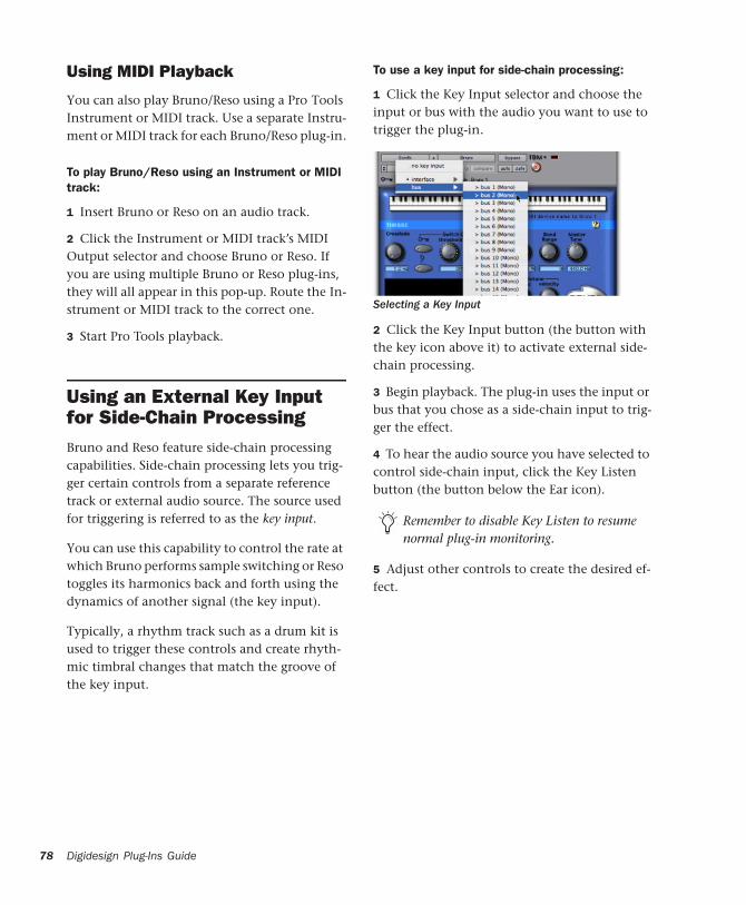
78
Using MIDI Playback
You can also play Bruno/Reso using a Pro Tools Instrument or MIDI track. Use a separate Instru-ment or MIDI track for each Bruno/Reso plug-in.
To play Bruno/Reso using an Instrument or MIDI track:
1 Insert Bruno or Reso on an audio track.
2 Click the Instrument or MIDI track’s MIDI Output selector and choose Bruno or Reso. If you are using multiple Bruno or Reso plug-ins, they will all appear in this pop-up. Route the In-strument or MIDI track to the correct one.
3 Start Pro Tools playback.
Using an External Key Input for Side-Chain ProcessingBruno and Reso feature side-chain processing capabilities. Side-chain processing lets you trig-ger certain controls from a separate reference track or external audio source. The source used for triggering is referred to as the key input.
You can use this capability to control the rate at which Bruno performs sample switching or Reso toggles its harmonics back and forth using the dynamics of another signal (the key input).
Typically, a rhythm track such as a drum kit is used to trigger these controls and create rhyth-mic timbral changes that match the groove of the key input.
Digidesign Plug-Ins Guide
To use a key input for side-chain processing:
1 Click the Key Input selector and choose the input or bus with the audio you want to use to trigger the plug-in.
2 Click the Key Input button (the button with the key icon above it) to activate external side-chain processing.
3 Begin playback. The plug-in uses the input or bus that you chose as a side-chain input to trig-ger the effect.
4 To hear the audio source you have selected to control side-chain input, click the Key Listen button (the button below the Ear icon).
5 Adjust other controls to create the desired ef-fect.
Selecting a Key Input
Remember to disable Key Listen to resume normal plug-in monitoring.
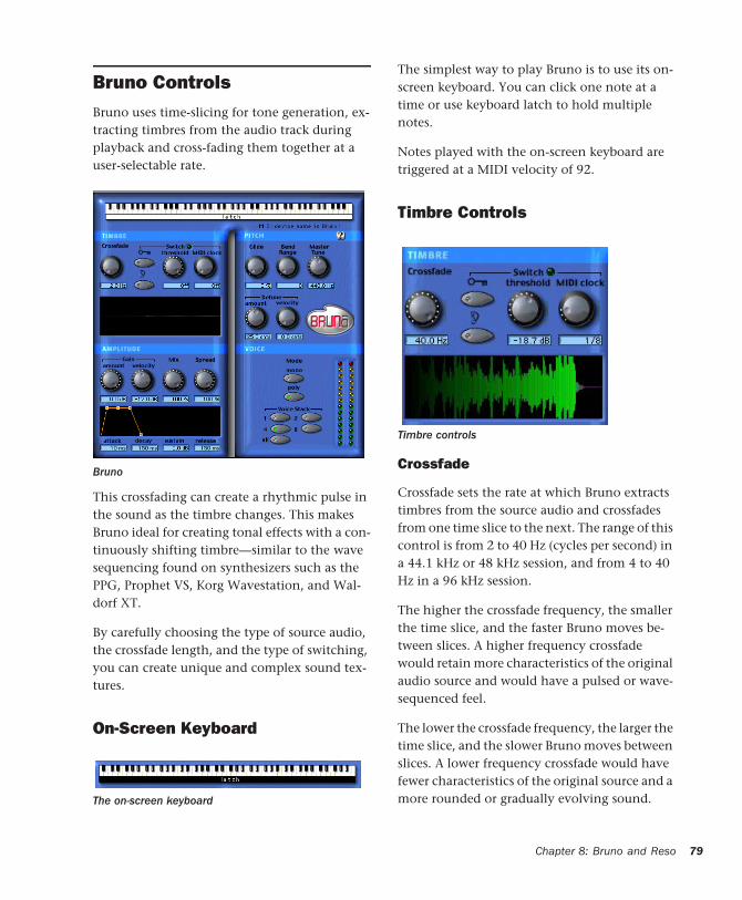
Bruno ControlsBruno uses time-slicing for tone generation, ex-tracting timbres from the audio track during playback and cross-fading them together at a user-selectable rate.
This crossfading can create a rhythmic pulse in the sound as the timbre changes. This makes Bruno ideal for creating tonal effects with a con-tinuously shifting timbre—similar to the wave sequencing found on synthesizers such as the PPG, Prophet VS, Korg Wavestation, and Wal-dorf XT.
By carefully choosing the type of source audio, the crossfade length, and the type of switching, you can create unique and complex sound tex-tures.
On-Screen Keyboard
Bruno
The on-screen keyboard
The simplest way to play Bruno is to use its on-screen keyboard. You can click one note at a time or use keyboard latch to hold multiple notes.
Notes played with the on-screen keyboard are triggered at a MIDI velocity of 92.
Timbre Controls
Crossfade
Crossfade sets the rate at which Bruno extracts timbres from the source audio and crossfades from one time slice to the next. The range of this control is from 2 to 40 Hz (cycles per second) in a 44.1 kHz or 48 kHz session, and from 4 to 40 Hz in a 96 kHz session.
The higher the crossfade frequency, the smaller the time slice, and the faster Bruno moves be-tween slices. A higher frequency crossfade would retain more characteristics of the original audio source and would have a pulsed or wave-sequenced feel.
The lower the crossfade frequency, the larger the time slice, and the slower Bruno moves between slices. A lower frequency crossfade would have fewer characteristics of the original source and a more rounded or gradually evolving sound.
Timbre controls
Chapter 8: Bruno and Reso 79

80
Switch
Switch causes Bruno to switch directly between time-sliced samples without crossfading them. This adds a distinct rhythmic pulse to the tim-bral changes.
Switching can be controlled by triggering (using the dynamics of the source audio or an external key input) or by MIDI clock.
External Key Enables switching from a separate reference track or external audio source. The source used for triggering is referred to as the key input and is selected using the Side-chain Input pop-up. You can assign either an audio input channel or a TDM bus channel.
Typically, a drum track is used as a key input so that switching occurs according to a definite rhythmic pattern.
Key Listen When enabled, Key Listen monitors the source of the key input. It is often useful to do this in order to fine tune Bruno’s settings to the key input. See “Using an External Key Input for Side-Chain Processing” on page 78.
Threshold Sets the level in decibels above which switching occurs. When the audio input level rises above the Threshold level, Bruno will switch directly to a new time-slice. The range of this control is from a low of –48 dB (maximum switching) to a high of 0.0 dB (no switching). If
Digidesign Plug-Ins Guide
no key input is used, the dynamics of the source audio will trigger switching. If a key input is used, the dynamics of the key input signal will trigger switching. Threshold-based switching can be used at the same time as Key Input-based switching.
MIDI Clock Triggers switching in sync with a MIDI Beat Clock signal. This creates a very regu-lar, highly rhythmic wave sequencing effect that is ideal for sessions arranged around MIDI beat clock. This control can be set to quarter, eighth, or sixteenth notes, or dotted triplet val-ues of the same.
Timbrometer
This multicolor waveform display shows the amplitude and duration of the audio signal gen-erated by Bruno as well as the frequency of tim-bral changes and whether they are crossfaded or switched.
Red and blue waveform segments indicate tim-bral changes that are crossfaded. Green wave-form segments indicate timbral changes that are hard switched.
For quick numeric entry of MIDI beat clock values, type “4,” “8,” or “16” for quarter notes, eight notes, or sixteenth notes. Add “t” for triplets, or “d” for dotted note values. Typing “4t” for example, enters a quarter note triplet value. Typing “16d” enters a dotted sixteenth note value.
Timbrometer
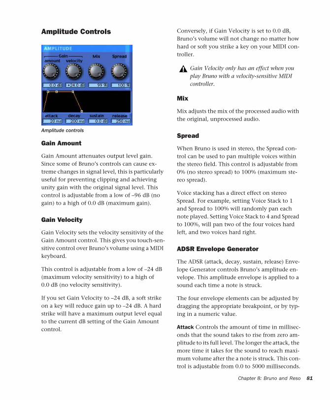
Amplitude Controls
Gain Amount
Gain Amount attenuates output level gain. Since some of Bruno’s controls can cause ex-treme changes in signal level, this is particularly useful for preventing clipping and achieving unity gain with the original signal level. This control is adjustable from a low of –96 dB (no gain) to a high of 0.0 dB (maximum gain).
Gain Velocity
Gain Velocity sets the velocity sensitivity of the Gain Amount control. This gives you touch-sen-sitive control over Bruno’s volume using a MIDI keyboard.
This control is adjustable from a low of –24 dB (maximum velocity sensitivity) to a high of 0.0 dB (no velocity sensitivity).
If you set Gain Velocity to –24 dB, a soft strike on a key will reduce gain up to –24 dB. A hard strike will have a maximum output level equal to the current dB setting of the Gain Amount control.
Amplitude controls
Conversely, if Gain Velocity is set to 0.0 dB, Bruno’s volume will not change no matter how hard or soft you strike a key on your MIDI con-troller.
Mix
Mix adjusts the mix of the processed audio with the original, unprocessed audio.
Spread
When Bruno is used in stereo, the Spread con-trol can be used to pan multiple voices within the stereo field. This control is adjustable from 0% (no stereo spread) to 100% (maximum ste-reo spread).
Voice stacking has a direct effect on stereo Spread. For example, setting Voice Stack to 1 and Spread to 100% will randomly pan each note played. Setting Voice Stack to 4 and Spread to 100%, will pan two of the four voices hard left, and two voices hard right.
ADSR Envelope Generator
The ADSR (attack, decay, sustain, release) Enve-lope Generator controls Bruno’s amplitude en-velope. This amplitude envelope is applied to a sound each time a note is struck.
The four envelope elements can be adjusted by dragging the appropriate breakpoint, or by typ-ing in a numeric value.
Attack Controls the amount of time in millisec-onds that the sound takes to rise from zero am-plitude to its full level. The longer the attack, the more time it takes for the sound to reach maxi-mum volume after the a note is struck. This con-trol is adjustable from 0.0 to 5000 milliseconds.
Gain Velocity only has an effect when you play Bruno with a velocity-sensitive MIDI controller.
Chapter 8: Bruno and Reso 81

82
Decay Controls the amount of time in millisec-onds that the sound takes to fall from its peak Attack level to the Sustain level. This control is adjustable from 0.0 ms to 5000 ms.
Sustain Level Controls the amplitude level in dB that is reached after the decay time has elapsed. The amplitude level stays constant as long as a MIDI note remains depressed. This control is ad-justable from –96 dB (no sustain) to 0.0 dB (maximum sustain).
Release Controls the amount of time in milli-seconds that the sound takes to fall from the Sustain level to zero amplitude after a note is re-leased. This control is adjustable from 0.0 ms to 5000 ms.
Pitch Controls
Glide
Glide, also known as portamento, determines the amount of time it takes for a pitch to glide from the current note to the next note played. This ef-fect is commonly found on synthesizers.
Pitch controls
Digidesign Plug-Ins Guide
Glide is adjustable from a low of 0.0% (no glide) to a high of 100% (maximum glide). A setting of 100% will take the longest time to travel from the current note to the next note played. The ef-fect is also dependent on the interval (distance of pitch) between the two notes: The larger the interval, the more noticeable the effect.
Bend Range
Bend Range sets the maximum interval of pitch bend that can be applied to Bruno with a MIDI controller’s pitch bend wheel. This control is ad-justable from 0 semitones (no bend) to 12 semi-tones (1 octave).
Master Tune
Master Tune can be used to tune the pitch of Bruno’s output to another instrument. By de-fault, this control is set to 440.0 Hz It can be ad-justed from a low of 430.0 Hz to a high of 450.0 Hz.
Detune Amount
Detuning is a common sound-thickening tech-nique used on synthesizers and many effects de-vices. Bruno’s Detune Amount control sets the maximum amount of pitch detuning that oc-curs when multiple voices are stacked together using Voice Stacking. Using a combination of voice stacking and detuning, you can create tim-bres that are exceptionally fat.
Voices can be detuned up to 50.0 cents. (One cent is equal to 1/100th of a semitone.)
Detune Velocity
Detune Velocity controls how MIDI key velocity affects voice detuning. This gives you velocity-sensitive control over voice detuning when you play Bruno with a MIDI keyboard.

This control is adjustable from a low of 0.0 cents (no velocity-sensitive detuning) to a high of 50.0 cents (maximum velocity-sensitive detun-ing).
If Detune Velocity is set to 0.0 cents, detuning will not change no matter how hard you strike a key on your MIDI controller. Conversely, if you set Detune Velocity to 50.0 cents, a hard strike will detune voices a maximum of 50.0 cents (in addition to the detuning specified with the De-tune Amount control).
Voice Controls
These controls set Bruno’s voice polyphony and allocation.
Mode
Mono (Monophonic)
In this mode, Bruno responds monophonically, producing a single note even if more than one is played simultaneously (though multiple voices can be stacked on the same note using the Voice Stacking control). Monophonic mode gives voice priority to the most recently played note.
Detune Velocity has an effect only when you play Bruno with a velocity-sensitive MIDI controller.
Voice controls
Poly (Polyphonic)
In this mode, Bruno responds polyphonically, producing as many notes as are played simulta-neously (up to 62 on Pro Tools|HD Accel sys-tems). The number of notes that can be played simultaneously depends on the Voice Stacking setting chosen. A voice stack setting of 1, for ex-ample, allows up to 62 individual notes simulta-neously. A voice stack setting of All allows only one note at a time, but will stack all 62 voices on that note, producing an extremely fat sound.
Voice Stack
Voice Stack selects the number of voices that are used, or stacked when you play a single note. The number of voices that you choose to stack will directly affect polyphony. Selecting a larger number of stacked voices will reduce the num-ber of notes that you can play simultaneously.
The sample rate of your session also affects po-lyphony. For example, in a 96 kHz session, Bruno can simultaneously play up to:
• 32 notes in a 1-voice stack
• 16 notes in a 2-voice stack
• 4 notes in a 4-voice stack
• 2 notes in an 8-voice stack
• 1 note in an 12-voice (All) stack
Voice Stack
The 62-voice Bruno requires an HD Accel card.
Chapter 8: Bruno and Reso 83
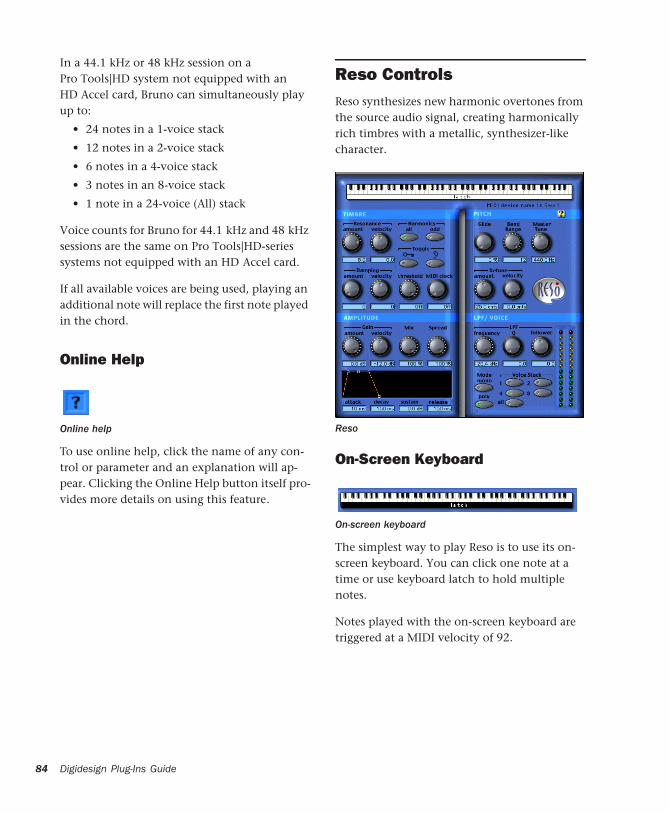
84
In a 44.1 kHz or 48 kHz session on a Pro Tools|HD system not equipped with an HD Accel card, Bruno can simultaneously play up to:
• 24 notes in a 1-voice stack
• 12 notes in a 2-voice stack
• 6 notes in a 4-voice stack
• 3 notes in an 8-voice stack
• 1 note in a 24-voice (All) stack
Voice counts for Bruno for 44.1 kHz and 48 kHz sessions are the same on Pro Tools|HD-series systems not equipped with an HD Accel card.
If all available voices are being used, playing an additional note will replace the first note played in the chord.
Online Help
To use online help, click the name of any con-trol or parameter and an explanation will ap-pear. Clicking the Online Help button itself pro-vides more details on using this feature.
Online help
Digidesign Plug-Ins Guide
Reso ControlsReso synthesizes new harmonic overtones from the source audio signal, creating harmonically rich timbres with a metallic, synthesizer-like character.
On-Screen Keyboard
The simplest way to play Reso is to use its on-screen keyboard. You can click one note at a time or use keyboard latch to hold multiple notes.
Notes played with the on-screen keyboard are triggered at a MIDI velocity of 92.
Reso
On-screen keyboard
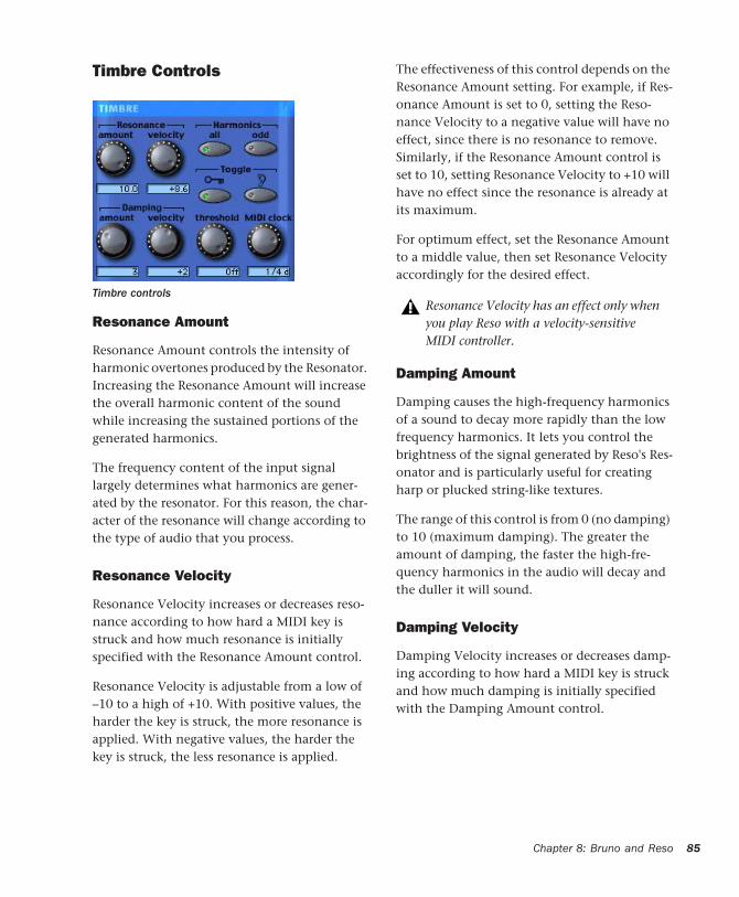
Timbre Controls
Resonance Amount
Resonance Amount controls the intensity of harmonic overtones produced by the Resonator. Increasing the Resonance Amount will increase the overall harmonic content of the sound while increasing the sustained portions of the generated harmonics.
The frequency content of the input signal largely determines what harmonics are gener-ated by the resonator. For this reason, the char-acter of the resonance will change according to the type of audio that you process.
Resonance Velocity
Resonance Velocity increases or decreases reso-nance according to how hard a MIDI key is struck and how much resonance is initially specified with the Resonance Amount control.
Resonance Velocity is adjustable from a low of –10 to a high of +10. With positive values, the harder the key is struck, the more resonance is applied. With negative values, the harder the key is struck, the less resonance is applied.
Timbre controls
The effectiveness of this control depends on the Resonance Amount setting. For example, if Res-onance Amount is set to 0, setting the Reso-nance Velocity to a negative value will have no effect, since there is no resonance to remove. Similarly, if the Resonance Amount control is set to 10, setting Resonance Velocity to +10 will have no effect since the resonance is already at its maximum.
For optimum effect, set the Resonance Amount to a middle value, then set Resonance Velocity accordingly for the desired effect.
Damping Amount
Damping causes the high-frequency harmonics of a sound to decay more rapidly than the low frequency harmonics. It lets you control the brightness of the signal generated by Reso's Res-onator and is particularly useful for creating harp or plucked string-like textures.
The range of this control is from 0 (no damping) to 10 (maximum damping). The greater the amount of damping, the faster the high-fre-quency harmonics in the audio will decay and the duller it will sound.
Damping Velocity
Damping Velocity increases or decreases damp-ing according to how hard a MIDI key is struck and how much damping is initially specified with the Damping Amount control.
Resonance Velocity has an effect only when you play Reso with a velocity-sensitive MIDI controller.
Chapter 8: Bruno and Reso 85
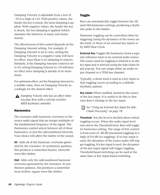
86
Damping Velocity is adjustable from a low of –10 to a high of +10. With positive values, the harder the key is struck, the more damping is ap-plied. With negative values, the harder the key is struck, the less damping is applied (which simulates the behavior of many real instru-ments).
The effectiveness of this control depends on the Damping Amount setting. For example, if Damping Amount is set to zero, setting the Damping Velocity to a negative value will have no effect, since there is no damping to remove. Similarly, if the Damping Amount control is set to 10, setting Damping Velocity to +10 will have no effect since damping is already at its maxi-mum.
For optimum effect, set the Damping Amount to a middle value, then set Damping Velocity ac-cordingly for the desired effect.
Harmonics
The resonator adds harmonic overtones to the source audio signal that are integer multiples of the fundamental frequency of the signal. The Harmonics control selects between all of these harmonics, or just the odd-numbered intervals. Your choice will affect the timbre of the sound.
All Adds all of the harmonic overtones gener-ated by the resonator. In synthesizer parlance, this produces a somewhat buzzier, sawtooth wave-like timbre.
Odd Adds only the odd-numbered harmonic overtones generated by the resonator. In syn-thesizer parlance, this produces a somewhat more hollow, square wave-like timbre.
Damping Velocity only has an effect when you play Reso with a velocity-sensitive MIDI keyboard controller.
Digidesign Plug-Ins Guide
Toggle
Reso can automatically toggle between the All and Odd harmonics settings, producing a rhyth-mic pulse in the timbre.
Harmonic toggling can be controlled either by triggering (using the dynamics of the source au-dio itself, or those of an external key input) or by MIDI Beat Clock.
External Key Toggles the harmonics from a sepa-rate reference track or an external audio source. The source used for toggling is referred to as the key input and is selected using the Side-chain In-put pop-up. You can assign either an audio in-put channel or a TDM bus channel.
Typically, a drum track is used as a key input so that toggling occurs according to a definite rhythmic pattern.
Key Listen When enabled, monitors the source of the key input. It is useful to do this to fine tune Reso’s settings to the key input.
Threshold Sets the level in decibels above which toggling occurs. When the audio input level rises above the Threshold level, Reso will toggle its harmonics setting. The range of this control is from a low of –48 dB (maximum toggling) to a high of 0.0 dB (no toggling). If no key input is used, the dynamics of the source audio will trig-ger toggling. If a key input is used, the dynamics of the key input signal will trigger toggling. Threshold-based switching can be used at the same time as Key Input-based switching.
See “Using an External Key Input for Side-Chain Processing” on page 78.

MIDI Clock Triggers toggling in sync with a MIDI Beat Clock signal. This creates a very regu-lar, highly rhythmic wave sequencing effect that is ideal for sessions arranged around MIDI beat clock. This control can be set to quarter, eighth, or sixteenth notes, or dotted triplet val-ues of the same.
Amplitude Controls
Gain Amount
Gain Amount attenuates output level gain. Since resonation can cause extreme changes in signal level, this is particularly useful for pre-venting clipping and achieving unity gain with the original signal level. This control is adjust-able from a low of –96 dB (no gain) to a high of 0.0 dB (maximum gain).
For quick numeric entry of MIDI beat clock values, type “4,” “8,” or “16” for quarter notes, eight notes, or sixteenth notes. Add “t” for triplets, or “d” for dotted note values. Typing “4t” for example, enters a quarter note triplet value. Typing “16d” enters a dotted sixteenth note value.
Amplitude controls
Gain Velocity
Gain Velocity sets the velocity sensitivity of the Gain Amount control. This gives you touch-sen-sitive control over Reso’s volume using a MIDI keyboard.
This control is adjustable from a low of –24 dB (maximum velocity sensitivity) to a high of 0.0 dB (no velocity sensitivity).
If you set Gain Velocity to –24 dB, a soft strike on a key will reduce gain up to –24 dB. A hard strike will have a maximum output level equal to the current dB setting of the Gain Amount control.
Conversely, if Gain Velocity is set to 0.0 dB, Reso’s volume will not change no matter how hard or soft you strike a key on your MIDI con-troller).
Mix
Mix adjusts the mix of the processed audio with the original, unprocessed audio.
Spread
When Reso is used in stereo, the Spread control can be used to pan multiple Reso voices within the stereo field. This control is adjustable from 0% (no stereo spread) to 100% (maximum ste-reo spread).
Voice stacking affects stereo Spread. For exam-ple, setting Voice Stack to 1 and Spread to 100% will alternately pan each note played right and left. Setting Voice Stack to 4 and Spread to 100%, will pan two of the five voices hard left, and two voices hard right.
Gain Velocity only has an effect when you play Reso with a velocity-sensitive MIDI keyboard controller.
Chapter 8: Bruno and Reso 87
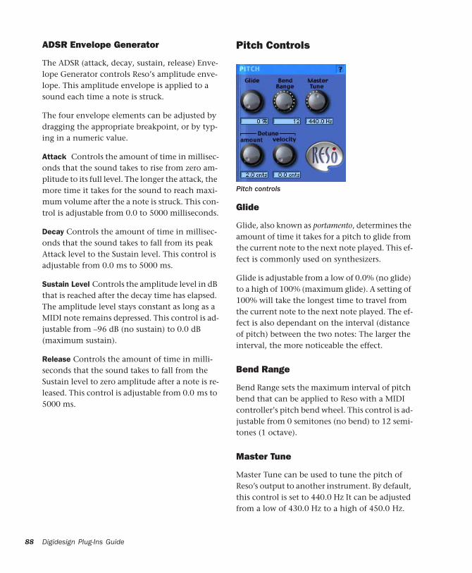
88
ADSR Envelope Generator
The ADSR (attack, decay, sustain, release) Enve-lope Generator controls Reso’s amplitude enve-lope. This amplitude envelope is applied to a sound each time a note is struck.
The four envelope elements can be adjusted by dragging the appropriate breakpoint, or by typ-ing in a numeric value.
Attack Controls the amount of time in millisec-onds that the sound takes to rise from zero am-plitude to its full level. The longer the attack, the more time it takes for the sound to reach maxi-mum volume after the a note is struck. This con-trol is adjustable from 0.0 to 5000 milliseconds.
Decay Controls the amount of time in millisec-onds that the sound takes to fall from its peak Attack level to the Sustain level. This control is adjustable from 0.0 ms to 5000 ms.
Sustain Level Controls the amplitude level in dB that is reached after the decay time has elapsed. The amplitude level stays constant as long as a MIDI note remains depressed. This control is ad-justable from –96 dB (no sustain) to 0.0 dB (maximum sustain).
Release Controls the amount of time in milli-seconds that the sound takes to fall from the Sustain level to zero amplitude after a note is re-leased. This control is adjustable from 0.0 ms to 5000 ms.
Digidesign Plug-Ins Guide
Pitch Controls
Glide
Glide, also known as portamento, determines the amount of time it takes for a pitch to glide from the current note to the next note played. This ef-fect is commonly used on synthesizers.
Glide is adjustable from a low of 0.0% (no glide) to a high of 100% (maximum glide). A setting of 100% will take the longest time to travel from the current note to the next note played. The ef-fect is also dependant on the interval (distance of pitch) between the two notes: The larger the interval, the more noticeable the effect.
Bend Range
Bend Range sets the maximum interval of pitch bend that can be applied to Reso with a MIDI controller’s pitch bend wheel. This control is ad-justable from 0 semitones (no bend) to 12 semi-tones (1 octave).
Master Tune
Master Tune can be used to tune the pitch of Reso’s output to another instrument. By default, this control is set to 440.0 Hz It can be adjusted from a low of 430.0 Hz to a high of 450.0 Hz.
Pitch controls
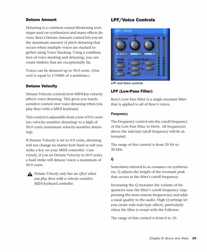
Detune Amount
Detuning is a common sound-thickening tech-nique used on synthesizers and many effects de-vices. Reso’s Detune Amount control lets you set the maximum amount of pitch detuning that occurs when multiple voices are stacked to-gether using Voice Stacking. Using a combina-tion of voice stacking and detuning, you can create timbres that are exceptionally fat.
Voices can be detuned up to 50.0 cents. (One cent is equal to 1/100th of a semitone.)
Detune Velocity
Detune Velocity controls how MIDI key velocity affects voice detuning. This gives you touch-sensitive control over voice detuning when you play Reso with a MIDI keyboard.
This control is adjustable from a low of 0.0 cents (no velocity-sensitive detuning) to a high of 50.0 cents (maximum velocity-sensitive detun-ing).
If Detune Velocity is set to 0.0 cents, detuning will not change no matter how hard or soft you strike a key on your MIDI controller. Con-versely, if you set Detune Velocity to 50.0 cents, a hard strike will detune voices a maximum of 50.0 cents.
Detune Velocity only has an effect when you play Reso with a velocity-sensitive MIDI keyboard controller.
LPF/Voice Controls
LPF (Low-Pass Filter)
Reso’s Low-Pass Filter is a single resonant filter that is applied to all of Reso’s voices.
Frequency
The Frequency control sets the cutoff frequency of the Low-Pass Filter in Hertz. All frequencies above the selected cutoff frequency will be at-tenuated.
The range of this control is from 20 Hz to 20 kHz.
Q
Sometimes referred to as resonance on synthesiz-ers, Q adjusts the height of the resonant peak that occurs at the filter’s cutoff frequency.
Increasing the Q increases the volume of fre-quencies near the filter’s cutoff frequency (sup-pressing the more remote frequencies) and adds a nasal quality to the audio. High Q settings let you create wah-wah type effects, particularly when the filter is swept with the Follower.
The range of this control is from 0 to 10.
LPF and Voice controls
Chapter 8: Bruno and Reso 89

90
Follower
The Follower is an envelope follower that lets the filter cutoff frequency dynamically follow the amplitude of the source audio signal.
The range of this control is from a low of –10 to a high of +10. With positive values, the louder the source audio, the higher the cutoff fre-quency and the wider the filter will open for a brighter sound. With negative values, the louder the source audio, the lower the cutoff frequency and the more the filter will close for a duller sound.
The effectiveness of the Follower depends on the filter’s Frequency setting. For example, set-ting the Follower to +10 and selecting a low Fre-quency setting will sweep the filter wide on loud passages. However, if the cutoff frequency is at its maximum, setting the Follower to +10 will not sweep the filter at all since it is already com-pletely open.
When used with high Q settings and a relatively low cutoff frequency, the Follower can be used to produce an automatic wah-wah-type effect.
Mono (Monophonic)
In this mode, Reso responds monophonically, producing a single note even if more than one is played simultaneously (though multiple voices can be stacked on the same note using the Voice Stacking control). Monophonic mode gives voice priority to the most recently played note.
Digidesign Plug-Ins Guide
Poly (Polyphonic)
In this mode, Reso responds polyphonically, producing as many notes as are played simulta-neously (up to 62 on Pro Tools|HD Accel sys-tems). The number of notes that can be played simultaneously depends on the Voice Stacking setting chosen. A voice stack setting of 1, for ex-ample, allows up to 62 individual notes simulta-neously. A voice stack setting of All allows only one note at a time, but will stack all 62 voices on that note, producing an extremely fat sound.
Voice Stack
Voice Stack selects the number of voices that are used, or stacked when you play a single note. The number of voices that you choose to stack will directly affect polyphony. Selecting a larger number of stacked voices will reduce the num-ber of notes that you can play simultaneously. The sample rate of your session will also affect polyphony.
In a 96 kHz session, Reso on Pro Tools|HD Accel systems can simultaneously play up to:
• 32 notes in a 1-voice stack
• 16 notes in a 2-voice stack
• 4 notes in a 4-voice stack
• 2 notes in an 8-voice stack
• 1 note in an 14-voice (All) stack
Polyphony will be reduced by half at 96 kHz.
Voice Stack
In a 44.1 kHz or 48 kHz session on Pro Tools|HD systems not equipped with an HD Accel card, the standard Reso module can simultaneously play up to:
• 28 notes in a 1-voice stack
• 14 notes in a 2-voice stack
• 7 notes in a 4-voice stack
• 3 notes in an 8-voice stack
• 1 note in a 28-voice (All) stack
If all available voices are being used, playing an additional note will replace the first note played in the chord.
Online Help
To use online help, click the name of any con-trol or parameter and an explanation will ap-pear. Clicking the Online Help button itself pro-vides more details on using this feature.
Online help
Chapter 8: Bruno and Reso 91

92
Digidesign Plug-Ins Guide
chapter 9
Reverb One
Reverb One is a world-class reverb processing TDM plug-in. It provides a level of sonic quality and reverb-shaping control previously found only on the most advanced hardware reverbera-tion units.
A set of unique, easy-to-use audio shaping tools lets you customize reverb character and ambi-ence to create natural-sounding halls, vintage plates, or virtually any type of reverberant space you can imagine.
Reverb One features include:
• Editable Reverb EQ graph
• Editable Reverb Color graph
• Reverb Contour graph
• Dynamic control of reverb decay
• Chorusing
• Early reflection presets
• Extensive library of reverb presets
• Supports 44.1 khz, 48 kHz, 88.2 kHz, and 96 kHz processing.
For sessions with a sample rate greater than 96 kHz, Reverb One will downsample and upsample accordingly.
A Reverb OverviewDigital reverberation processing can simulate the complex natural reflections and echoes that occur after a sound has been produced, impart-ing a sense of space and depth—the signature of an acoustic environment. When you use a rever-beration plug-in such as Reverb One, you are ar-tificially creating a sound space with a specific acoustic character.
This character can be melded with audio mate-rial, with the end result being an adjustable mix of the original dry source and the reverberant wet signal. Reverberation can take relatively life-less mono source material and create a stereo acoustic environment that gives the source a perceived weight and depth in a mix.
Creating Unique Sounds
In addition, digital signal processing can be used creatively to produce reverberation characteris-tics that do not exist in nature. There are no rules that need to be followed to produce inter-esting treatments. Experimentation can often produce striking new sounds.
Acoustic Environments
When you hear live sound in an acoustic envi-ronment, you generally hear much more than just the direct sound from the source. In fact,
Chapter 9: Reverb One 93
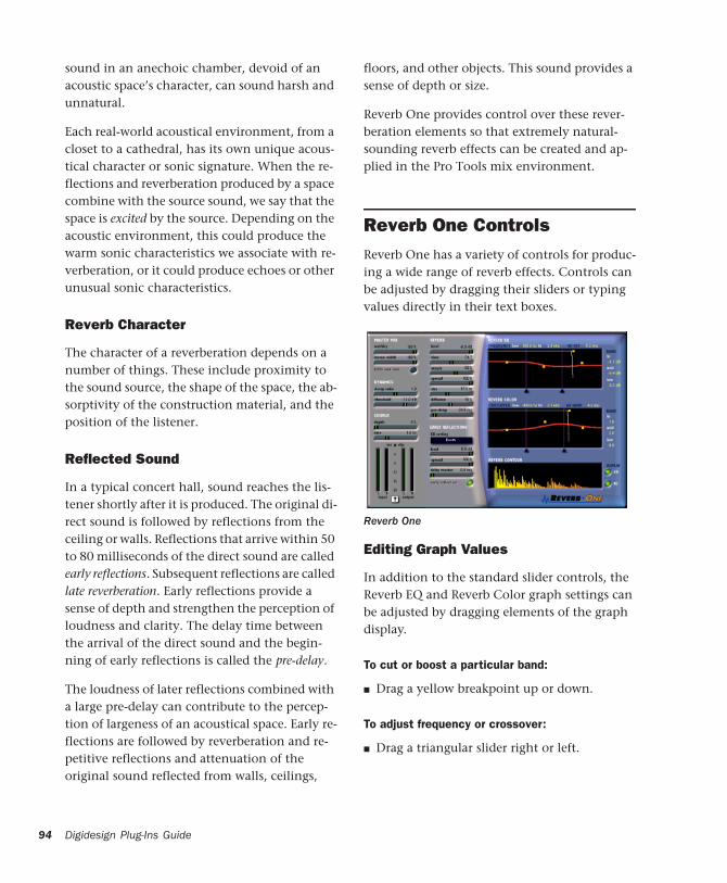
94
sound in an anechoic chamber, devoid of an acoustic space’s character, can sound harsh and unnatural.
Each real-world acoustical environment, from a closet to a cathedral, has its own unique acous-tical character or sonic signature. When the re-flections and reverberation produced by a space combine with the source sound, we say that the space is excited by the source. Depending on the acoustic environment, this could produce the warm sonic characteristics we associate with re-verberation, or it could produce echoes or other unusual sonic characteristics.
Reverb Character
The character of a reverberation depends on a number of things. These include proximity to the sound source, the shape of the space, the ab-sorptivity of the construction material, and the position of the listener.
Reflected Sound
In a typical concert hall, sound reaches the lis-tener shortly after it is produced. The original di-rect sound is followed by reflections from the ceiling or walls. Reflections that arrive within 50 to 80 milliseconds of the direct sound are called early reflections. Subsequent reflections are called late reverberation. Early reflections provide a sense of depth and strengthen the perception of loudness and clarity. The delay time between the arrival of the direct sound and the begin-ning of early reflections is called the pre-delay.
The loudness of later reflections combined with a large pre-delay can contribute to the percep-tion of largeness of an acoustical space. Early re-flections are followed by reverberation and re-petitive reflections and attenuation of the original sound reflected from walls, ceilings,
Digidesign Plug-Ins Guide
floors, and other objects. This sound provides a sense of depth or size.
Reverb One provides control over these rever-beration elements so that extremely natural-sounding reverb effects can be created and ap-plied in the Pro Tools mix environment.
Reverb One ControlsReverb One has a variety of controls for produc-ing a wide range of reverb effects. Controls can be adjusted by dragging their sliders or typing values directly in their text boxes.
Editing Graph Values
In addition to the standard slider controls, the Reverb EQ and Reverb Color graph settings can be adjusted by dragging elements of the graph display.
To cut or boost a particular band:
■ Drag a yellow breakpoint up or down.
To adjust frequency or crossover:
■ Drag a triangular slider right or left.
Reverb One
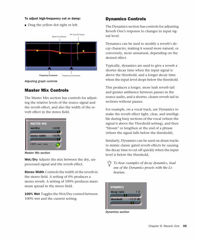
To adjust high-frequency cut or damp:
■ Drag the yellow dot right or left.
Master Mix Controls
The Master Mix section has controls for adjust-ing the relative levels of the source signal and the reverb effect, and also the width of the re-verb effect in the stereo field.
Wet/Dry Adjusts the mix between the dry, un-processed signal and the reverb effect.
Stereo Width Controls the width of the reverb in the stereo field. A setting of 0% produces a mono reverb. A setting of 100% produces maxi-mum spread in the stereo field.
100% Wet Toggles the Wet/Dry control between 100% wet and the current setting.
Adjusting graph controls
Master Mix section
HF Cut/HF DampBand Cut/Boost
Frequency/CrossoverFrequency/Crossover Frequency/Crossover
Dynamics Controls
The Dynamics section has controls for adjusting Reverb One’s response to changes in input sig-nal level.
Dynamics can be used to modify a reverb’s de-cay character, making it sound more natural, or conversely, more unnatural, depending on the desired effect.
Typically, dynamics are used to give a reverb a shorter decay time when the input signal is above the threshold, and a longer decay time when the input level drops below the threshold.
This produces a longer, more lush reverb tail and greater ambience between pauses in the source audio, and a shorter, clearer reverb tail in sections without pauses.
For example, on a vocal track, use Dynamics to make the reverb effect tight, clear, and intelligi-ble during busy sections of the vocal (where the signal is above the Threshold setting), and then “bloom” or lengthen at the end of a phrase (where the signal falls below the threshold).
Similarly, Dynamics can be used on drum tracks to mimic classic gated reverb effects by causing the decay time to cut off quickly when the input level is below the threshold.
To hear examples of decay dynamics, load one of the Dynamics presets with the Li-brarian.
Dynamics section
Chapter 9: Reverb One 95
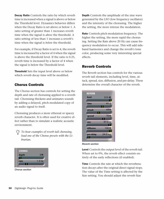
96
Decay Ratio Controls the ratio by which reverb time is increased when a signal is above or below the Threshold level. Dynamics behavior differs when the Decay Ratio is set above or below 1. A ratio setting of greater than 1 increases reverb time when the signal is above the threshold. A ratio setting of less than 1 increases a reverb’s time when the signal is below the threshold.
For example, if Decay Ratio is set to 4, the reverb time is increased by a factor of 4 when the signal is above the threshold level. If the ratio is 0.25, reverb time is increased by a factor of 4 when the signal is below the Threshold level.
Threshold Sets the input level above or below which reverb decay time will be modified.
Chorus Controls
The Chorus section has controls for setting the depth and rate of chorusing applied to a reverb tail. Chorusing thickens and animates sounds by adding a delayed, pitch-modulated copy of an audio signal to itself.
Chorusing produces a more ethereal or spacey reverb character. It is often used for creative ef-fect rather than to simulate a realistic acoustic environment.
To hear examples of reverb tail chorusing, load one of the Chorus presets with the Li-brarian.
Chorus section
Digidesign Plug-Ins Guide
Depth Controls the amplitude of the sine wave generated by the LFO (low frequency oscillator) and the intensity of the chorusing. The higher the setting, the more intense the modulation.
Rate Controls pitch modulation frequency. The higher the setting, the more rapid the chorus-ing. Setting the Rate above 20 Hz can cause fre-quency modulation to occur. This will add side-band harmonics and change the reverb’s tone color, producing some very interesting special effects.
Reverb Controls
The Reverb section has controls for the various reverb tail elements, including level, time, at-tack, spread, size, diffusion, and pre-delay. These determine the overall character of the reverb.
Level Controls the output level of the reverb tail. When set to 0%, the reverb effect consists en-tirely of the early reflections (if enabled).
Time Controls the rate at which the reverbera-tion decays after the original direct signal stops. The value of the Time setting is affected by the Size setting. You should adjust the reverb Size
Reverb section
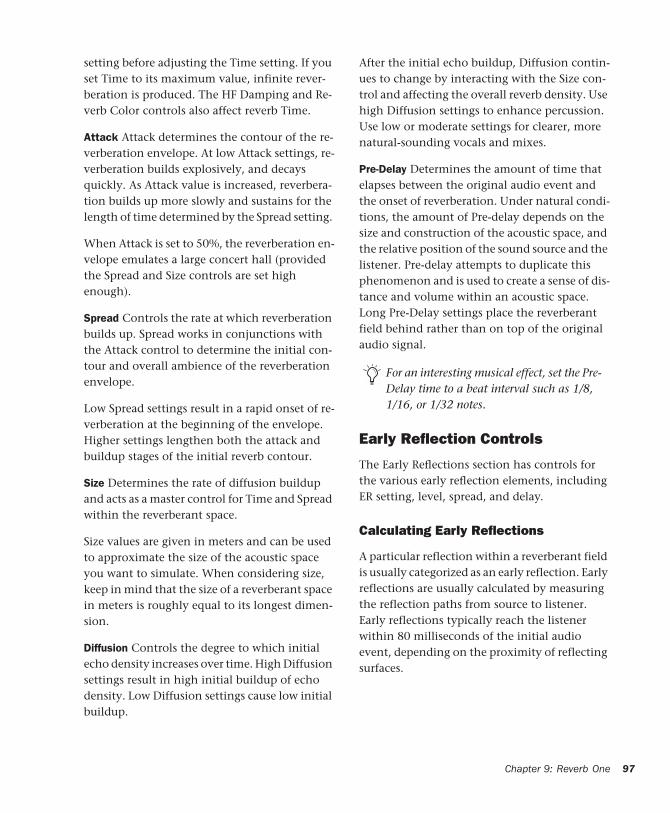
setting before adjusting the Time setting. If you set Time to its maximum value, infinite rever-beration is produced. The HF Damping and Re-verb Color controls also affect reverb Time.
Attack Attack determines the contour of the re-verberation envelope. At low Attack settings, re-verberation builds explosively, and decays quickly. As Attack value is increased, reverbera-tion builds up more slowly and sustains for the length of time determined by the Spread setting.
When Attack is set to 50%, the reverberation en-velope emulates a large concert hall (provided the Spread and Size controls are set high enough).
Spread Controls the rate at which reverberation builds up. Spread works in conjunctions with the Attack control to determine the initial con-tour and overall ambience of the reverberation envelope.
Low Spread settings result in a rapid onset of re-verberation at the beginning of the envelope. Higher settings lengthen both the attack and buildup stages of the initial reverb contour.
Size Determines the rate of diffusion buildup and acts as a master control for Time and Spread within the reverberant space.
Size values are given in meters and can be used to approximate the size of the acoustic space you want to simulate. When considering size, keep in mind that the size of a reverberant space in meters is roughly equal to its longest dimen-sion.
Diffusion Controls the degree to which initial echo density increases over time. High Diffusion settings result in high initial buildup of echo density. Low Diffusion settings cause low initial buildup.
After the initial echo buildup, Diffusion contin-ues to change by interacting with the Size con-trol and affecting the overall reverb density. Use high Diffusion settings to enhance percussion. Use low or moderate settings for clearer, more natural-sounding vocals and mixes.
Pre-Delay Determines the amount of time that elapses between the original audio event and the onset of reverberation. Under natural condi-tions, the amount of Pre-delay depends on the size and construction of the acoustic space, and the relative position of the sound source and the listener. Pre-delay attempts to duplicate this phenomenon and is used to create a sense of dis-tance and volume within an acoustic space. Long Pre-Delay settings place the reverberant field behind rather than on top of the original audio signal.
Early Reflection Controls
The Early Reflections section has controls for the various early reflection elements, including ER setting, level, spread, and delay.
Calculating Early Reflections
A particular reflection within a reverberant field is usually categorized as an early reflection. Early reflections are usually calculated by measuring the reflection paths from source to listener. Early reflections typically reach the listener within 80 milliseconds of the initial audio event, depending on the proximity of reflecting surfaces.
For an interesting musical effect, set the Pre-Delay time to a beat interval such as 1/8, 1/16, or 1/32 notes.
Chapter 9: Reverb One 97
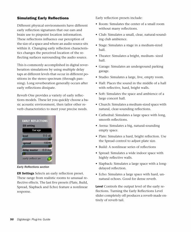
98
Simulating Early Reflections
Different physical environments have different early reflection signatures that our ears and brain use to pinpoint location information. These reflections influence our perception of the size of a space and where an audio source sits within it. Changing early reflection characteris-tics changes the perceived location of the re-flecting surfaces surrounding the audio source.
This is commonly accomplished in digital rever-beration simulations by using multiple delay taps at different levels that occur in different po-sitions in the stereo spectrum (through pan-ning). Long reverberation generally occurs after early reflections dissipate.
Reverb One provides a variety of early reflec-tions models. These let you quickly choose a ba-sic acoustic environment, then tailor other re-verb characteristics to meet your precise needs.
ER Settings Selects an early reflection preset. These range from realistic rooms to unusual re-flective effects. The last five presets (Plate, Build, Spread, Slapback and Echo) feature a nonlinear response.
Early Reflections section
Digidesign Plug-Ins Guide
Early reflection presets include:
• Room: Simulates the center of a small room without many reflections.
• Club: Simulates a small, clear, natural-sound-ing club ambience.
• Stage: Simulates a stage in a medium-sized hall.
• Theater: Simulates a bright, medium- sized hall.
• Garage: Simulates an underground parking garage.
• Studio: Simulates a large, live, empty room.
• Hall: Places the sound in the middle of a hall with reflective, hard, bright walls.
• Soft: Simulates the space and ambience of a large concert hall.
• Church: Simulates a medium-sized space with natural, clear-sounding reflections.
• Cathedral: Simulates a large space with long, smooth reflections.
• Arena: Simulates a big, natural-sounding empty space.
• Plate: Simulates a hard, bright reflection. Use the Spread control to adjust plate size.
• Build: A nonlinear series of reflections
• Spread: Simulates a wide indoor space with highly reflective walls.
• Slapback: Simulates a large space with a long-delayed reflection.
• Echo: Simulates a large space with hard, un-natural echoes. Good for dense reverb.
Level Controls the output level of the early re-flections. Turning the Early Reflections Level slider completely off produces a reverb made en-tirely of reverb tail.
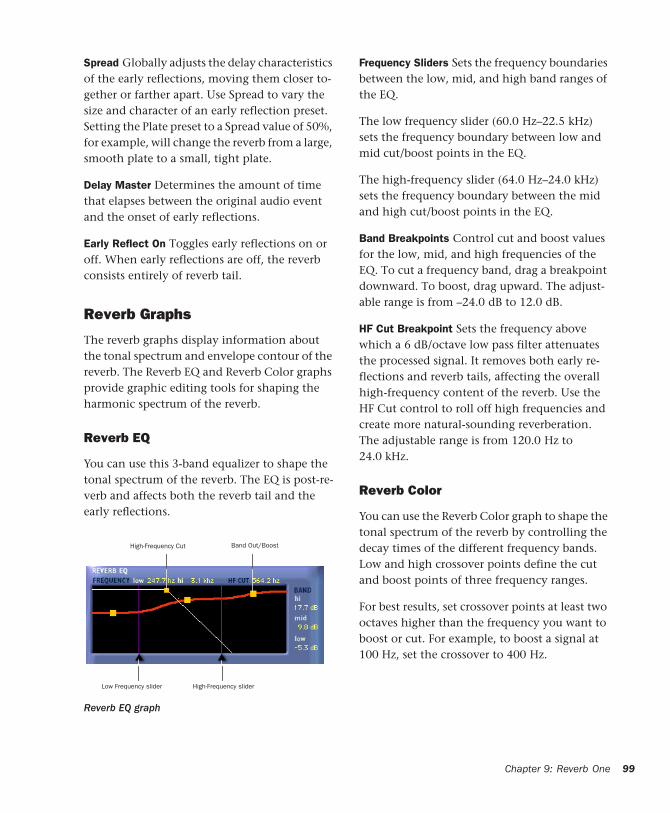
Spread Globally adjusts the delay characteristics of the early reflections, moving them closer to-gether or farther apart. Use Spread to vary the size and character of an early reflection preset. Setting the Plate preset to a Spread value of 50%, for example, will change the reverb from a large, smooth plate to a small, tight plate.
Delay Master Determines the amount of time that elapses between the original audio event and the onset of early reflections.
Early Reflect On Toggles early reflections on or off. When early reflections are off, the reverb consists entirely of reverb tail.
Reverb Graphs
The reverb graphs display information about the tonal spectrum and envelope contour of the reverb. The Reverb EQ and Reverb Color graphs provide graphic editing tools for shaping the harmonic spectrum of the reverb.
Reverb EQ
You can use this 3-band equalizer to shape the tonal spectrum of the reverb. The EQ is post-re-verb and affects both the reverb tail and the early reflections.
Reverb EQ graph
High-Frequency Cut Band Out/Boost
Low Frequency slider High-Frequency slider
Frequency Sliders Sets the frequency boundaries between the low, mid, and high band ranges of the EQ.
The low frequency slider (60.0 Hz–22.5 kHz) sets the frequency boundary between low and mid cut/boost points in the EQ.
The high-frequency slider (64.0 Hz–24.0 kHz) sets the frequency boundary between the mid and high cut/boost points in the EQ.
Band Breakpoints Control cut and boost values for the low, mid, and high frequencies of the EQ. To cut a frequency band, drag a breakpoint downward. To boost, drag upward. The adjust-able range is from –24.0 dB to 12.0 dB.
HF Cut Breakpoint Sets the frequency above which a 6 dB/octave low pass filter attenuates the processed signal. It removes both early re-flections and reverb tails, affecting the overall high-frequency content of the reverb. Use the HF Cut control to roll off high frequencies and create more natural-sounding reverberation. The adjustable range is from 120.0 Hz to 24.0 kHz.
Reverb Color
You can use the Reverb Color graph to shape the tonal spectrum of the reverb by controlling the decay times of the different frequency bands. Low and high crossover points define the cut and boost points of three frequency ranges.
For best results, set crossover points at least two octaves higher than the frequency you want to boost or cut. For example, to boost a signal at 100 Hz, set the crossover to 400 Hz.
Chapter 9: Reverb One 99
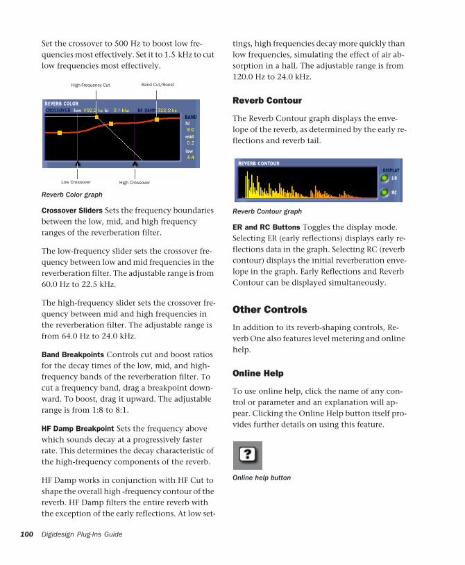
100
Set the crossover to 500 Hz to boost low fre-quencies most effectively. Set it to 1.5 kHz to cut low frequencies most effectively.
Crossover Sliders Sets the frequency boundaries between the low, mid, and high frequency ranges of the reverberation filter.
The low-frequency slider sets the crossover fre-quency between low and mid frequencies in the reverberation filter. The adjustable range is from 60.0 Hz to 22.5 kHz.
The high-frequency slider sets the crossover fre-quency between mid and high frequencies in the reverberation filter. The adjustable range is from 64.0 Hz to 24.0 kHz.
Band Breakpoints Controls cut and boost ratios for the decay times of the low, mid, and high-frequency bands of the reverberation filter. To cut a frequency band, drag a breakpoint down-ward. To boost, drag it upward. The adjustable range is from 1:8 to 8:1.
HF Damp Breakpoint Sets the frequency above which sounds decay at a progressively faster rate. This determines the decay characteristic of the high-frequency components of the reverb.
HF Damp works in conjunction with HF Cut to shape the overall high -frequency contour of the reverb. HF Damp filters the entire reverb with the exception of the early reflections. At low set-
Reverb Color graph
High-Frequency Cut Band Cut/Boost
Low Crossover High Crossover
Digidesign Plug-Ins Guide
tings, high frequencies decay more quickly than low frequencies, simulating the effect of air ab-sorption in a hall. The adjustable range is from 120.0 Hz to 24.0 kHz.
Reverb Contour
The Reverb Contour graph displays the enve-lope of the reverb, as determined by the early re-flections and reverb tail.
ER and RC Buttons Toggles the display mode. Selecting ER (early reflections) displays early re-flections data in the graph. Selecting RC (reverb contour) displays the initial reverberation enve-lope in the graph. Early Reflections and Reverb Contour can be displayed simultaneously.
Other Controls
In addition to its reverb-shaping controls, Re-verb One also features level metering and online help.
Online Help
To use online help, click the name of any con-trol or parameter and an explanation will ap-pear. Clicking the Online Help button itself pro-vides further details on using this feature.
Reverb Contour graph
Online help button
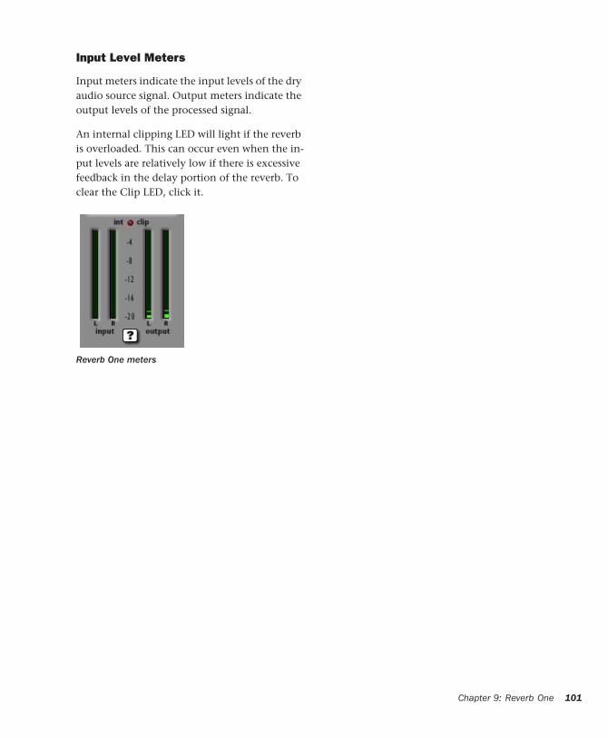
Input Level Meters
Input meters indicate the input levels of the dry audio source signal. Output meters indicate the output levels of the processed signal.
An internal clipping LED will light if the reverb is overloaded. This can occur even when the in-put levels are relatively low if there is excessive feedback in the delay portion of the reverb. To clear the Clip LED, click it.
Reverb One meters
Chapter 9: Reverb One 101

102
Digidesign Plug-Ins Guide
chapter 10
SoundReplacer
SoundReplacer is an AudioSuite plug-in de-signed to replace audio elements such as drums, percussion, and sound effects in Pro Tools tracks with alternate sounds. SoundReplacer can quickly and intelligently match the timing and dynamics of original performance material, making it ideal for both music and audio post production.
SoundReplacer features:
• Sound replacement with phase-accurate peak alignment
• Intelligent tracking of source audio dynam-ics for matching the feel of the original per-formance
• Three separate amplitude zones per audio event for triggering different replacement samples according to performance dynam-ics
• Zoomable waveform display for precision threshold/amplitude zone adjustment
• Crossfading or hard-switching of replace-ment audio in different amplitude zones for optimum realism and flexibility
• Online help
Audio Replacement TechniquesReplacing audio elements during the course of a recording session is a fairly common scenario. In music production it is often done in order to replace or augment an element that lacks punch. In film or video post-production it is typically done to improve or vary a specific sound cue or effect.
In the past, engineers and producers had to rely on sampling audio delay lines or MIDI triggered audio samplers—methods that had distinct dis-advantages. Delay lines, for example, support only a single replacement sample, and while they can track the amplitude of the source events, the replacement sample itself remains the same at different amplitude levels.
The result is static and unnatural. In addition to these drawbacks, sample triggers are notoriously difficult to set up for accurate timing.
Similarly, with MIDI triggered samplers, MIDI timing and event triggering are inconsistent, re-sulting in problems with phase and frequency response when the original audio is mixed with the triggered replacement sounds.
Chapter 10: SoundReplacer 103
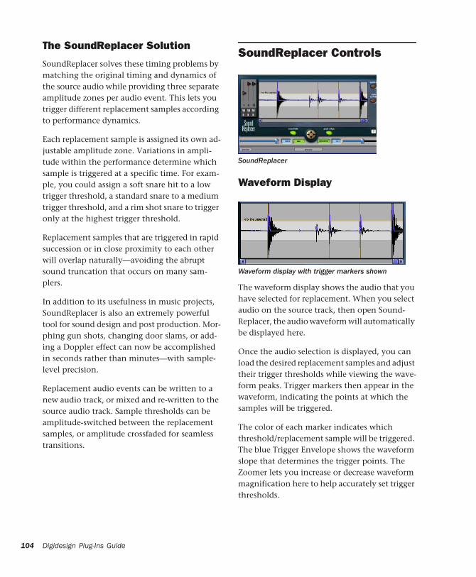
104
The SoundReplacer Solution
SoundReplacer solves these timing problems by matching the original timing and dynamics of the source audio while providing three separate amplitude zones per audio event. This lets you trigger different replacement samples according to performance dynamics.
Each replacement sample is assigned its own ad-justable amplitude zone. Variations in ampli-tude within the performance determine which sample is triggered at a specific time. For exam-ple, you could assign a soft snare hit to a low trigger threshold, a standard snare to a medium trigger threshold, and a rim shot snare to trigger only at the highest trigger threshold.
Replacement samples that are triggered in rapid succession or in close proximity to each other will overlap naturally—avoiding the abrupt sound truncation that occurs on many sam-plers.
In addition to its usefulness in music projects, SoundReplacer is also an extremely powerful tool for sound design and post production. Mor-phing gun shots, changing door slams, or add-ing a Doppler effect can now be accomplished in seconds rather than minutes—with sample-level precision.
Replacement audio events can be written to a new audio track, or mixed and re-written to the source audio track. Sample thresholds can be amplitude-switched between the replacement samples, or amplitude crossfaded for seamless transitions.
Digidesign Plug-Ins Guide
SoundReplacer Controls
Waveform Display
The waveform display shows the audio that you have selected for replacement. When you select audio on the source track, then open Sound-Replacer, the audio waveform will automatically be displayed here.
Once the audio selection is displayed, you can load the desired replacement samples and adjust their trigger thresholds while viewing the wave-form peaks. Trigger markers then appear in the waveform, indicating the points at which the samples will be triggered.
The color of each marker indicates which threshold/replacement sample will be triggered. The blue Trigger Envelope shows the waveform slope that determines the trigger points. The Zoomer lets you increase or decrease waveform magnification here to help accurately set trigger thresholds.
SoundReplacer
Waveform display with trigger markers shown

If you change the audio selection on the source track, click Update to update the waveform dis-play. If Auto Update is selected, SoundReplacer automatically updates the waveform display each time you make a new selection or begin playback.
Trigger Threshold
The color-coded Trigger Threshold sliders set a total of three amplitude zones (one for each re-placement audio file) for triggering replacement samples:
• The yellow slider represents amplitude zone 1, the lowest-level trigger.
• The red slider represents amplitude zone 2, the middle-level trigger.
• The blue slider represents amplitude zone 3, the highest-level trigger.
With a replacement sample loaded, drag the Threshold slider to the desired amplitude level. Color-coded trigger markers will appear in the Waveform at points where the source audio sig-nal exceeds the threshold set for that amplitude zone. The replacement sample will be triggered at these points.
If you frequently change selections or start and stop playback, turn off Auto Update to prevent too-frequent redraws.
Threshold controls
The color of the Trigger markers correspond to the matching Threshold slider. This lets you see at a glance which replacement samples will be triggered and where they will be triggered.
Load/Unload Sound
Clicking the Load/Unload Sound icons loads or unloads replacement samples for each of the three trigger threshold amplitude zones. Click-ing the Floppy Disk icon loads a new sample (or replaces the current sample). Clicking the Trash Can icon unloads the current sample.
If you zoom the waveform display below a specific Trigger Threshold slider’s ampli-tude zone, the slider will be temporarily un-available. To access the slider again, zoom back out to an appropriate magnification level.
Load/Unload Sound
SoundReplacer does not perform a sample rate conversion before loading replacement samples if they are at a different sample rate from the session. Replacement samples should be at the same sample rate as the session, otherwise they will playback at the wrong speed and pitch.
Chapter 10: SoundReplacer 105
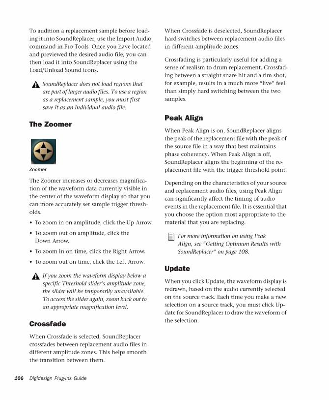
106
To audition a replacement sample before load-ing it into SoundReplacer, use the Import Audio command in Pro Tools. Once you have located and previewed the desired audio file, you can then load it into SoundReplacer using the Load/Unload Sound icons.
The Zoomer
The Zoomer increases or decreases magnifica-tion of the waveform data currently visible in the center of the waveform display so that you can more accurately set sample trigger thresh-olds.
• To zoom in on amplitude, click the Up Arrow.
• To zoom out on amplitude, click the Down Arrow.
• To zoom in on time, click the Right Arrow.
• To zoom out on time, click the Left Arrow.
Crossfade
When Crossfade is selected, SoundReplacer crossfades between replacement audio files in different amplitude zones. This helps smooth the transition between them.
SoundReplacer does not load regions that are part of larger audio files. To use a region as a replacement sample, you must first save it as an individual audio file.
Zoomer
If you zoom the waveform display below a specific Threshold slider’s amplitude zone, the slider will be temporarily unavailable. To access the slider again, zoom back out to an appropriate magnification level.
Digidesign Plug-Ins Guide
When Crossfade is deselected, SoundReplacer hard switches between replacement audio files in different amplitude zones.
Crossfading is particularly useful for adding a sense of realism to drum replacement. Crossfad-ing between a straight snare hit and a rim shot, for example, results in a much more “live” feel than simply hard switching between the two samples.
Peak Align
When Peak Align is on, SoundReplacer aligns the peak of the replacement file with the peak of the source file in a way that best maintains phase coherency. When Peak Align is off, SoundReplacer aligns the beginning of the re-placement file with the trigger threshold point.
Depending on the characteristics of your source and replacement audio files, using Peak Align can significantly affect the timing of audio events in the replacement file. It is essential that you choose the option most appropriate to the material that you are replacing.
Update
When you click Update, the waveform display is redrawn, based on the audio currently selected on the source track. Each time you make a new selection on a source track, you must click Up-date for SoundReplacer to draw the waveform of the selection.
For more information on using Peak Align, see “Getting Optimum Results with SoundReplacer” on page 108.
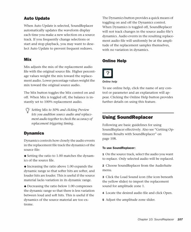
Auto Update
When Auto Update is selected, SoundReplacer automatically updates the waveform display each time you make a new selection on a source track. If you frequently change selections or start and stop playback, you may want to dese-lect Auto Update to prevent frequent redraws.
Mix
Mix adjusts the mix of the replacement audio file with the original source file. Higher percent-age values weight the mix toward the replace-ment audio. Lower percentage values weight the mix toward the original source audio.
The Mix button toggles the Mix control on and off. When Mix is toggled off, the balance is in-stantly set to 100% replacement audio.
Dynamics
Dynamics controls how closely the audio events in the replacement file track the dynamics of the source file:
◆ Setting the ratio to 1.00 matches the dynam-ics of the source file.
◆ Increasing the ratio above 1.00 expands the dynamic range so that softer hits are softer, and louder hits are louder. This is useful if the source material lacks variation in its dynamic range.
◆ Decreasing the ratio below 1.00 compresses the dynamic range so that there is less variation between loud and soft hits. This is useful if the dynamics of the source material are too ex-treme.
Setting Mix to 50% and clicking Preview lets you audition source audio and replace-ment audio together to check the accuracy of replacement triggering timing.
The Dynamics button provides a quick means of toggling on and off the Dynamics control. When Dynamics is toggled off, SoundReplacer will not track changes in the source audio file’s dynamics. Audio events in the resulting replace-ment audio file will uniformly be at the ampli-tude of the replacement samples themselves, with no variation in dynamics.
Online Help
To use online help, click the name of any con-trol or parameter and an explanation will ap-pear. Clicking the Online Help button provides further details on using this feature.
Using SoundReplacerFollowing are basic guidelines for using SoundReplacer effectively. Also see “Getting Op-timum Results with SoundReplacer” on page 108.
To use SoundReplacer:
1 On the source track, select the audio you want to replace. Only selected audio will be replaced.
2 Choose SoundReplacer from the AudioSuite menu.
3 Click the Load Sound icon (the icon beneath the yellow slider) to import the replacement sound for amplitude zone 1.
4 Locate the desired audio file and click Open.
5 Adjust the amplitude zone slider.
Online help
Chapter 10: SoundReplacer 107
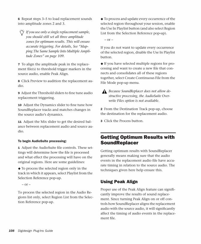
108
6 Repeat steps 3–5 to load replacement sounds into amplitude zones 2 and 3.
7 To align the amplitude peak in the replace-ment file(s) to threshold trigger markers in the source audio, enable Peak Align.
8 Click Preview to audition the replacement au-dio.
9 Adjust the Threshold sliders to fine tune audio replacement triggering.
10 Adjust the Dynamics slider to fine tune how SoundReplacer tracks and matches changes in the source audio’s dynamics.
11 Adjust the Mix slider to get the desired bal-ance between replacement audio and source au-dio.
To begin AudioSuite processing:
1 Adjust the AudioSuite file controls. These set-tings will determine how the file is processed and what effect the processing will have on the original regions. Here are some guidelines:
◆ To process the selected region only in the track in which it appears, select Playlist from the Selection Reference pop-up.
– or –
To process the selected region in the Audio Re-gions list only, select Region List from the Selec-tion Reference pop-up.
If you use only a single replacement sample, you should still set all three amplitude zones for optimum results. This will ensure accurate triggering. For details, See “Map-ping The Same Sample Into Multiple Ampli-tude Zones” on page 109.
Digidesign Plug-Ins Guide
◆ To process and update every occurrence of the selected region throughout your session, enable the Use In Playlist button (and also select Region List from the Selection Reference pop-up).
– or –
If you do not want to update every occurrence of the selected region, disable the Use In Playlist button.
◆ If you have selected multiple regions for pro-cessing and want to create a new file that con-nects and consolidates all of these regions together, select Create Continuous File from the File Mode pop-up menu.
2 From the Destination Track pop-up, choose the destination for the replacement audio.
3 Click the Process button.
Getting Optimum Results with SoundReplacerGetting optimum results with SoundReplacer generally means making sure that the audio events in the replacement audio file have accu-rate timing in relation to the source audio. The techniques given here help ensure this.
Using Peak Align
Proper use of the Peak Align feature can signifi-cantly improve the results of sound replace-ment. Since turning Peak Align on or off con-trols how SoundReplacer aligns the replacement audio with the source audio, it will significantly affect the timing of audio events in the replace-ment file.
Because SoundReplacer does not allow de-structive processing, the AudioSuite Over-write Files option is not available.

In general:
◆ Turn on Peak Align if you are replacing drum or percussion sounds whose peak level occurs at the initial attack.
◆ Turn off Peak Align if you are replacing sounds whose peak level occurs somewhere after the initial attack. Peak Align should also be turned off if the sounds you are replacing are not drum or percussion sounds.
To illustrate why Peak Align makes a difference, look at the following illustrations:
Figure 1 shows a kick drum whose peak level oc-curs at its initial attack.
Figure 2 shows a kick drum whose peak level oc-curs after its initial attack.
Figure 1. A fast-peaking kick drum
Figure 2. A slower-peaking kick drum
If you turn on Peak Align and attempt to replace the fast-peaking kick with the slow-peaking kick (or vice-versa), SoundReplacer will align their peaks—which occur at different points in the sound. The audible result would be that the re-placement audio file (slow-peaking kick) would trigger too early.
Mapping The Same Sample Into Multiple Amplitude Zones
If you are performing drum replacement and in-tend to use just a single replacement sample, mapping it into multiple amplitude zones will ensure more accurate triggering. Here is why:
Imagine that you are replacing a kick drum part. If you look at the waveform of a kick drum, you will often see a “pre-hit” portion of the sound that occurs as soon as the ball of the kick pedal hits the drum. This is rapidly followed by the denser attack portion of the sound, where most of sound’s weight is.
With a sound like this, using a single amplitude threshold presents a problem because typically, in pop music, kick drum parts consist of loud ac-cent hits and softer off-beat hits that are often 6 dB or more lower in level.
A kick drum with a pre-hit preceding a denser attack
Chapter 10: SoundReplacer 109
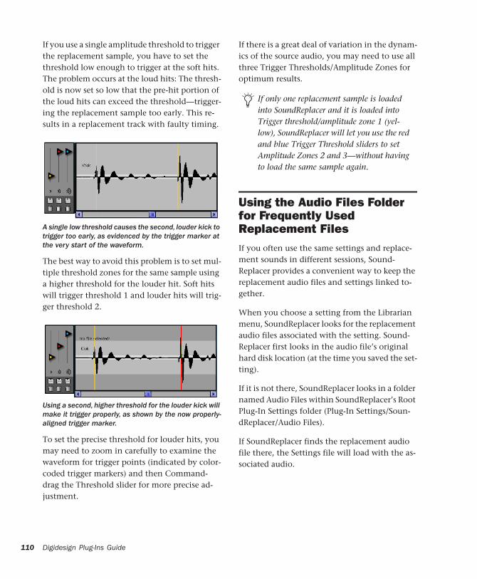
110
If you use a single amplitude threshold to trigger the replacement sample, you have to set the threshold low enough to trigger at the soft hits. The problem occurs at the loud hits: The thresh-old is now set so low that the pre-hit portion of the loud hits can exceed the threshold—trigger-ing the replacement sample too early. This re-sults in a replacement track with faulty timing.
The best way to avoid this problem is to set mul-tiple threshold zones for the same sample using a higher threshold for the louder hit. Soft hits will trigger threshold 1 and louder hits will trig-ger threshold 2.
To set the precise threshold for louder hits, you may need to zoom in carefully to examine the waveform for trigger points (indicated by color-coded trigger markers) and then Command-drag the Threshold slider for more precise ad-justment.
A single low threshold causes the second, louder kick to trigger too early, as evidenced by the trigger marker at the very start of the waveform.
Using a second, higher threshold for the louder kick will make it trigger properly, as shown by the now properly-aligned trigger marker.
Digidesign Plug-Ins Guide
If there is a great deal of variation in the dynam-ics of the source audio, you may need to use all three Trigger Thresholds/Amplitude Zones for optimum results.
Using the Audio Files Folder for Frequently Used Replacement FilesIf you often use the same settings and replace-ment sounds in different sessions, Sound-Replacer provides a convenient way to keep the replacement audio files and settings linked to-gether.
When you choose a setting from the Librarian menu, SoundReplacer looks for the replacement audio files associated with the setting. Sound-Replacer first looks in the audio file’s original hard disk location (at the time you saved the set-ting).
If it is not there, SoundReplacer looks in a folder named Audio Files within SoundReplacer’s Root Plug-In Settings folder (Plug-In Settings/Soun-dReplacer/Audio Files).
If SoundReplacer finds the replacement audio file there, the Settings file will load with the as-sociated audio.
If only one replacement sample is loaded into SoundReplacer and it is loaded into Trigger threshold/amplitude zone 1 (yel-low), SoundReplacer will let you use the red and blue Trigger Threshold sliders to set Amplitude Zones 2 and 3—without having to load the same sample again.
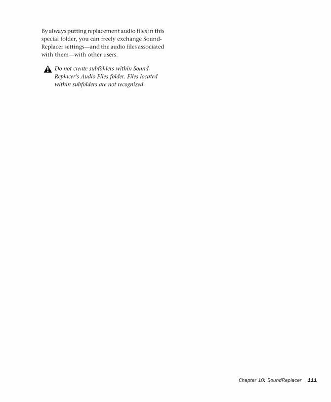
By always putting replacement audio files in this special folder, you can freely exchange Sound-Replacer settings—and the audio files associated with them—with other users.
Do not create subfolders within Sound-Replacer’s Audio Files folder. Files located within subfolders are not recognized.
Chapter 10: SoundReplacer 111

112
Digidesign Plug-Ins Guide
chapter 11
SurroundScope
SurroundScope is a TDM and RTAS plug-in that assists with multichannel mixing by visually representing the phase, individual input levels, and position of multichannel signals in the sur-round field.
SurroundScope supports all industry-standard, multichannel formats, including LCR, Quad, LCRS, and 5.0, 5.1, 6.0, 6.1, 7.0, and 7.1.
SurroundScope features include:
• 360° Surround Display indicates signal po-sition within the surround field.
• Lissajous meter ensures perfect stereo im-ages by indicating amplitude and phase.
• High-resolution meters accurately display individual input channel levels as low as –60 dB.
• Stereo Phase meter indicates signal phase.
• SurroundScope operates in both TDM and RTAS plug-in formats.
For information on using SurroundScope during mixdown with Pro Tools, see the Pro Tools Reference Guide.
Using SurroundScopeSince it has no user-adjustable controls, SurroundScope is extremely easy to use. Once inserted on a multichannel track or Master Fader, you can use it to accurately monitor phase, position, and input level metering of multichannel signals.
To use SurroundScope:
1 Click the Insert selector on the desired multi-channel track and choose SurroundScope from the plug-in pop-up menu.
2 Begin audio playback.
3 Watch the Surround Display, Phase meter, and Input Level meters to visually monitor the mul-tichannel signal.
For more information about multichannel signals and multichannel mixing, refer to the Pro Tools Reference Guide.
Chapter 11: SurroundScope 113
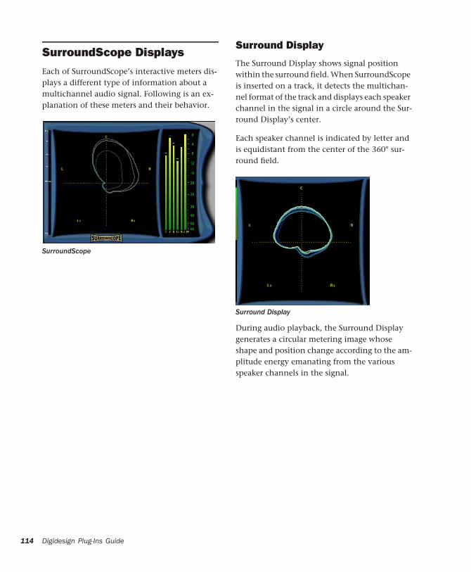
114
SurroundScope DisplaysEach of SurroundScope’s interactive meters dis-plays a different type of information about a multichannel audio signal. Following is an ex-planation of these meters and their behavior.
SurroundScope
Digidesign Plug-Ins Guide
Surround Display
The Surround Display shows signal position within the surround field. When SurroundScope is inserted on a track, it detects the multichan-nel format of the track and displays each speaker channel in the signal in a circle around the Sur-round Display’s center.
Each speaker channel is indicated by letter and is equidistant from the center of the 360° sur-round field.
During audio playback, the Surround Display generates a circular metering image whose shape and position change according to the am-plitude energy emanating from the various speaker channels in the signal.
Surround Display
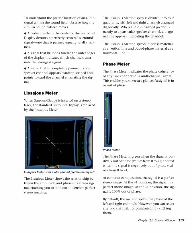
To understand the precise location of an audio signal within the sound field, observe how the circular sound pattern moves:
◆ A perfect circle in the center of the Surround Display denotes a perfectly centered surround signal—one that is panned equally to all chan-nels.
◆ A signal that balloons toward the outer edges of the display indicates which channels ema-nate the strongest signal.
◆ A signal that is completely panned to one speaker channel appears teardrop-shaped and points toward the channel emanating the sig-nal.
Lissajous Meter
When SurroundScope is inserted on a stereo track, the standard Surround Display is replaced by the Lissajous Meter.
The Lissajous Meter shows the relationship be-tween the amplitude and phase of a stereo sig-nal, enabling you to monitor and ensure perfect stereo imaging.
Lissajous Meter with audio panned predominantly left
The Lissajous Meter display is divided into four quadrants, with left and right channels arranged diagonally. When audio is panned predomi-nantly to a particular speaker channel, a diago-nal line appears, indicating the channel.
The Lissajous Meter displays in-phase material as a vertical line and out-of-phase material as a horizontal line.
Phase Meter
The Phase Meter indicates the phase coherency of any two channels of a multichannel signal. This enables you to see at a glance if a signal is in or out of phase.
The Phase Meter is green when the signal is pos-itively out of phase (values from 0 to +1) and red when the signal is negatively out of phase (val-ues from 0 to –1).
At center or zero position, the signal is a perfect stereo image. At the +1 position, the signal is a perfect mono image. At the –1 position, the sig-nal is 100% out of phase.
By default, the meter displays the phase of the left and right channels. However, you can select any two channels for comparison by clicking them.
Phase Meter
Chapter 11: SurroundScope 115
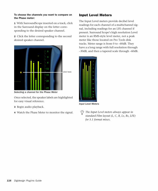
116
To choose the channels you want to compare on the Phase meter:
1 With SurroundScope inserted on a track, click in the Surround display on the letter corre-sponding to the desired speaker channel.
2 Click the letter corresponding to the second desired speaker channel.
Once selected, the speaker labels are highlighted for easy visual reference.
3 Begin audio playback.
4 Watch the Phase Meter to monitor the signal.
Selecting a channel for the Phase Meter
click here
Digidesign Plug-Ins Guide
Input Level Meters
The Input Level meters provide decibel level readings for each channel of a multichannel sig-nal, including readings for an LFE channel if present. Surround Scope’s high resolution Level meter is an RMS-style level meter, not a peak meter like those located on Pro Tools disk tracks. Meter range is from 0 to –60dB. They have a a long range with full resolution through –30dB, and then a tapered scale through –60dB.
Input Level Meters
The Input Level meters always appear in standard Film layout (L, C, R, Ls, Rs, LFE) for 5.1 format mixes.
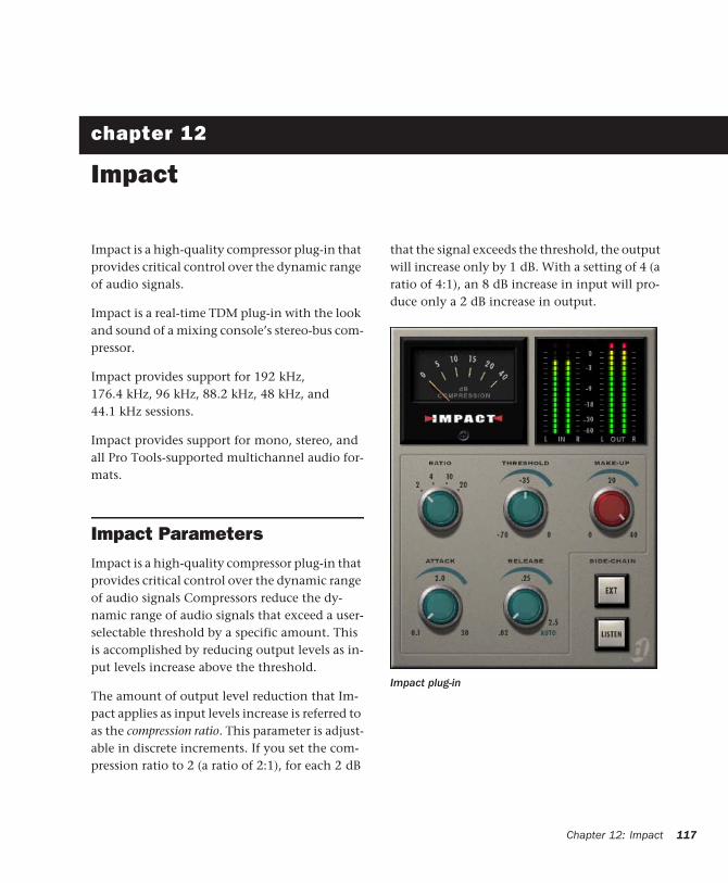
chapter 12
Impact
Impact is a high-quality compressor plug-in that provides critical control over the dynamic range of audio signals.
Impact is a real-time TDM plug-in with the look and sound of a mixing console’s stereo-bus com-pressor.
Impact provides support for 192 kHz, 176.4 kHz, 96 kHz, 88.2 kHz, 48 kHz, and 44.1 kHz sessions.
Impact provides support for mono, stereo, and all Pro Tools-supported multichannel audio for-mats.
Impact ParametersImpact is a high-quality compressor plug-in that provides critical control over the dynamic range of audio signals Compressors reduce the dy-namic range of audio signals that exceed a user-selectable threshold by a specific amount. This is accomplished by reducing output levels as in-put levels increase above the threshold.
The amount of output level reduction that Im-pact applies as input levels increase is referred to as the compression ratio. This parameter is adjust-able in discrete increments. If you set the com-pression ratio to 2 (a ratio of 2:1), for each 2 dB
that the signal exceeds the threshold, the output will increase only by 1 dB. With a setting of 4 (a ratio of 4:1), an 8 dB increase in input will pro-duce only a 2 dB increase in output.
Impact plug-in
Chapter 12: Impact 117
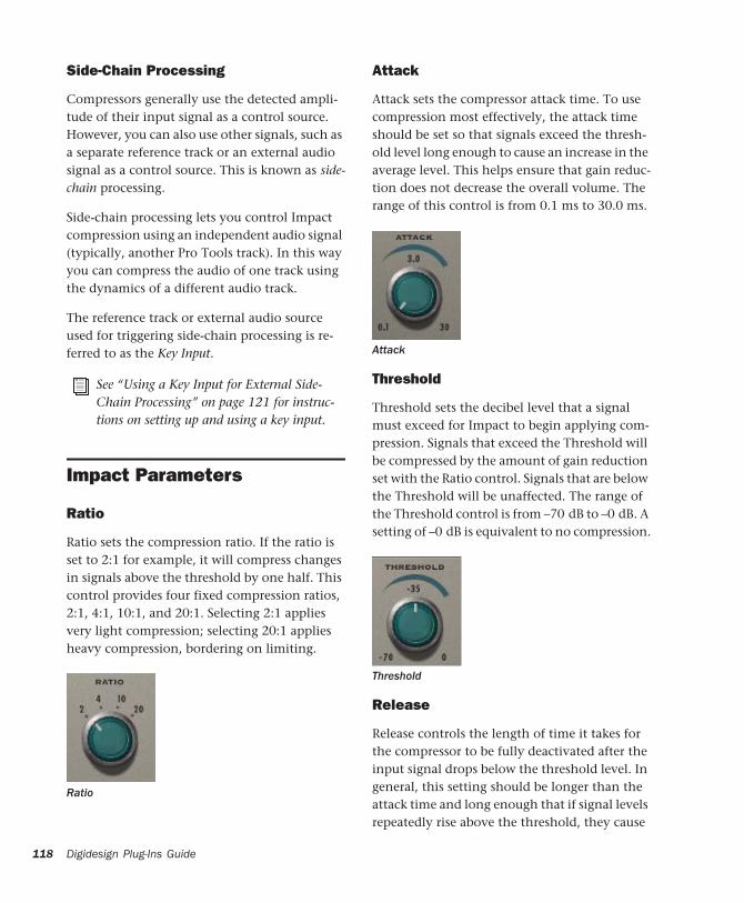
118
Side-Chain Processing
Compressors generally use the detected ampli-tude of their input signal as a control source. However, you can also use other signals, such as a separate reference track or an external audio signal as a control source. This is known as side-chain processing.
Side-chain processing lets you control Impact compression using an independent audio signal (typically, another Pro Tools track). In this way you can compress the audio of one track using the dynamics of a different audio track.
The reference track or external audio source used for triggering side-chain processing is re-ferred to as the Key Input.
Impact Parameters
Ratio
Ratio sets the compression ratio. If the ratio is set to 2:1 for example, it will compress changes in signals above the threshold by one half. This control provides four fixed compression ratios, 2:1, 4:1, 10:1, and 20:1. Selecting 2:1 applies very light compression; selecting 20:1 applies heavy compression, bordering on limiting.
See “Using a Key Input for External Side-Chain Processing” on page 121 for instruc-tions on setting up and using a key input.
Ratio
Digidesign Plug-Ins Guide
Attack
Attack sets the compressor attack time. To use compression most effectively, the attack time should be set so that signals exceed the thresh-old level long enough to cause an increase in the average level. This helps ensure that gain reduc-tion does not decrease the overall volume. The range of this control is from 0.1 ms to 30.0 ms.
Threshold
Threshold sets the decibel level that a signal must exceed for Impact to begin applying com-pression. Signals that exceed the Threshold will be compressed by the amount of gain reduction set with the Ratio control. Signals that are below the Threshold will be unaffected. The range of the Threshold control is from –70 dB to –0 dB. A setting of –0 dB is equivalent to no compression.
Release
Release controls the length of time it takes for the compressor to be fully deactivated after the input signal drops below the threshold level. In general, this setting should be longer than the attack time and long enough that if signal levels repeatedly rise above the threshold, they cause
Attack
Threshold
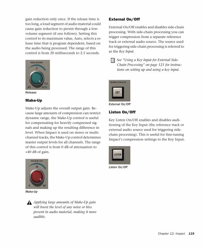
gain reduction only once. If the release time is too long, a loud segment of audio material could cause gain reduction to persist through a low-volume segment (if one follows). Setting this control to its maximum value, Auto, selects a re-lease time that is program dependent, based on the audio being processed. The range of this control is from 20 milliseconds to 2.5 seconds.
Make-Up
Make-Up adjusts the overall output gain. Be-cause large amounts of compression can restrict dynamic range, the Make-Up control is useful for compensating for heavily compressed sig-nals and making up the resulting difference in level. When Impact is used on stereo or multi-channel tracks, the Make-Up control determines master output levels for all channels. The range of this control is from 0 dB of attenuation to +40 dB of gain.
Release
Make-Up
Applying large amounts of Make-Up gain will boost the level of any noise or hiss present in audio material, making it more audible.
External On/Off
External On/Off enables and disables side-chain processing. With side-chain processing you can trigger compression from a separate reference track or external audio source. The source used for triggering side-chain processing is referred to as the Key Input.
Listen On/Off
Key Listen On/Off enables and disables audi-tioning of the Key Input (the reference track or external audio source used for triggering side-chain processing). This is useful for fine-tuning Impact’s compression settings to the Key Input.
See “Using a Key Input for External Side-Chain Processing” on page 121 for instruc-tions on setting up and using a key input.
External On/Off
Listen On/Off
Chapter 12: Impact 119
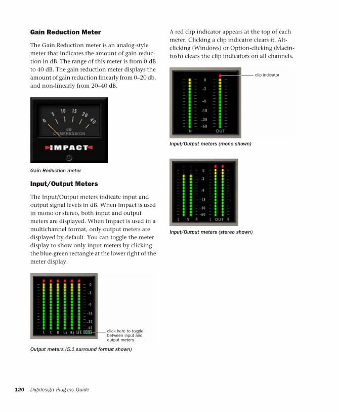
120
Gain Reduction Meter
The Gain Reduction meter is an analog-style meter that indicates the amount of gain reduc-tion in dB. The range of this meter is from 0 dB to 40 dB. The gain reduction meter displays the amount of gain reduction linearly from 0–20 db, and non-linearly from 20–40 dB.
Input/Output Meters
The Input/Output meters indicate input and output signal levels in dB. When Impact is used in mono or stereo, both input and output meters are displayed. When Impact is used in a multichannel format, only output meters are displayed by default. You can toggle the meter display to show only input meters by clicking the blue-green rectangle at the lower right of the meter display.
Gain Reduction meter
Output meters (5.1 surround format shown)
click here to togglebetween input andoutput meters
Digidesign Plug-Ins Guide
A red clip indicator appears at the top of each meter. Clicking a clip indicator clears it. Alt-clicking (Windows) or Option-clicking (Macin-tosh) clears the clip indicators on all channels.
Input/Output meters (mono shown)
Input/Output meters (stereo shown)
clip indicator

Using a Key Input for External Side-Chain ProcessingImpact provides side-chain processing capabili-ties. Side-chain processing lets you control Im-pact compression using an independent audio signal (typically, another Pro Tools track). In this way you can compress the audio of one track using the dynamics of a different audio track.
A typical use for side-chain processing is to con-trol the dynamics of one audio signal using the dynamics of another signal (referred to as the Key Input). For example, you could use a lead vocal track to trigger compression of a back-ground vocal track so that their dynamics match.
To use a Key Input signal for side-chain processing:
1 Click the Send button and select a bus path for the audio track or Auxiliary Input you want to use as the side-chain signal.
2 From Impact’s Key Input menu, select the in-put or bus path carrying the audio you want to use as the side-chain signal to trigger Impact compression. The Key Input source must be monophonic.
3 To activate external side-chain processing, click Ext.
4 Begin playback. Impact uses the input or bus that you selected as a Key Input to trigger its ef-fect.
5 If you want to hear the audio source you have selected as the side-chain input, click Listen. (To stop listening to the side-chain input, click Lis-ten again.)
6 Adjust Impact’s Threshold parameter to fine-tune Key Input triggering.
7 Adjust other parameters to achieve the desired effect.
Choosing a Key Input
Remember to disable Listen to resume nor-mal plug-in monitoring.
Chapter 12: Impact 121

122
Digidesign Plug-Ins Guide
chapter 13
ReVibe
ReVibe provides studio-quality reverb and acoustic environment modeling for mono, ste-reo, and greater-than-stereo multichannel audio formats. Revibe offers extensive control over re-verb characteristics, and a diverse array of room reflection and coloration presets.
ReVibe makes it possible to model extremely re-alistic acoustic spaces and place audio elements within them in a Pro Tools mix.
ReVibe requires one or more HD Accel cards.
ReVibe plug-in
Chapter 13: ReVibe 123

124
Reverberation ConceptsDigital reverberation processing can simulate the complex natural reflections and echoes that occur after a sound has been produced, impart-ing a sense of space and depth—the signature of an acoustic environment. When you use a rever-beration plug-in such as ReVibe, you are artifi-cially creating a sound space with a specific acoustic character.
This character can be melded with audio mate-rial, with the end result being an adjustable mix of the original dry source and the reverberant wet signal. You can use reverberation to en-hance relatively lifeless mono source material with a stereo acoustic environment that gives the source audio a perceived weight and depth in a mix.
Acoustic Environments
When you hear live sound in an acoustic envi-ronment, you generally hear much more than just the direct sound from the source. In fact, sound in an anechoic chamber, devoid of an acoustic space’s character, can sound harsh and unnatural.
Each real-world acoustical environment, from a closet to a cathedral, has its own unique acous-tical character or sonic signature. When the re-flections and reverberation produced by a space combine with the source sound, the space is said to be excited by the source. Depending on the acoustic environment, this could produce the warm sonic characteristics associated with re-verberation, or it could produce echoes or other unusual sonic characteristics.
Digidesign Plug-Ins Guide
Reverb Character
Reverb character depends on many factors in-cluding the shape of the space, the reflectivity of the construction material, the proximity of re-flective elements to the sound source, and the position of the listener.
Reflected Sound
In a typical concert hall, sound reaches the lis-tener shortly after it is produced. The original di-rect sound is followed by reflections from the ceiling or walls. These discrete reflections, which usually arrive within 100 milliseconds of the direct sound, are called early reflections. The subsequent, and more diffuse reflections, are called the reverb tail. The delay time between the arrival of the direct sound and the beginning of the reflected sounds is called the pre-delay.
The loudness and panning of early reflections combined with the length of the pre-delay can contribute to the perception of size of an acous-tical space.
ReVibe also uses Room Coloration to accurately model acoustic spaces and effects. Room Color-ation is a complex filter process, similar to EQ, that models the frequency shape of each room or effect.
ReVibe provides control over these reverb ele-ments so that extremely natural-sounding re-verb effects can be created and applied in the Pro Tools mix environment.
ReVibe can also be used to produce reverb char-acteristics that do not exist in nature. There are no rules that you need to follow to produce in-teresting treatments. Experimentation can often produce striking results.
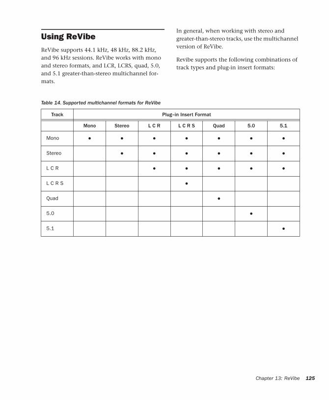
Using ReVibe ReVibe supports 44.1 kHz, 48 kHz, 88.2 kHz, and 96 kHz sessions. ReVibe works with mono and stereo formats, and LCR, LCRS, quad, 5.0, and 5.1 greater-than-stereo multichannel for-mats.
Table 14. Supported multichannel formats for ReVibe
In general, when working with stereo and greater-than-stereo tracks, use the multichannel version of ReVibe.
Revibe supports the following combinations of track types and plug-in insert formats:
Track Plug–in Insert Format
Mono Stereo L C R L C R S Quad 5.0 5.1
Mono • • • • • • •
Stereo • • • • • •
L C R • • • • •
L C R S •
Quad •
5.0 •
5.1 •
Chapter 13: ReVibe 125
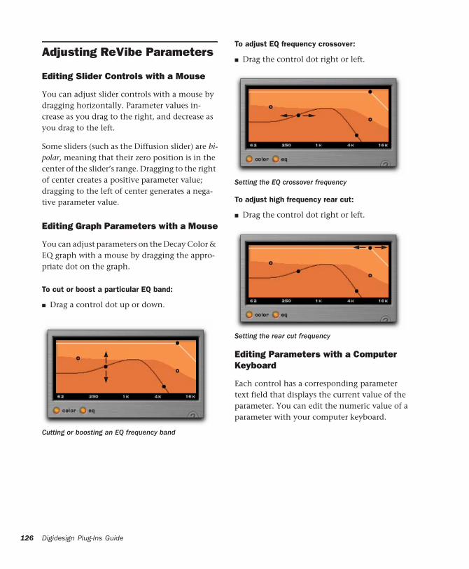
126
Adjusting ReVibe Parameters
Editing Slider Controls with a Mouse
You can adjust slider controls with a mouse by dragging horizontally. Parameter values in-crease as you drag to the right, and decrease as you drag to the left.
Some sliders (such as the Diffusion slider) are bi-polar, meaning that their zero position is in the center of the slider’s range. Dragging to the right of center creates a positive parameter value; dragging to the left of center generates a nega-tive parameter value.
Editing Graph Parameters with a Mouse
You can adjust parameters on the Decay Color & EQ graph with a mouse by dragging the appro-priate dot on the graph.
To cut or boost a particular EQ band:
■ Drag a control dot up or down.
Cutting or boosting an EQ frequency band
Digidesign Plug-Ins Guide
To adjust EQ frequency crossover:
■ Drag the control dot right or left.
To adjust high frequency rear cut:
■ Drag the control dot right or left.
Editing Parameters with a Computer Keyboard
Each control has a corresponding parameter text field that displays the current value of the parameter. You can edit the numeric value of a parameter with your computer keyboard.
Setting the EQ crossover frequency
Setting the rear cut frequency
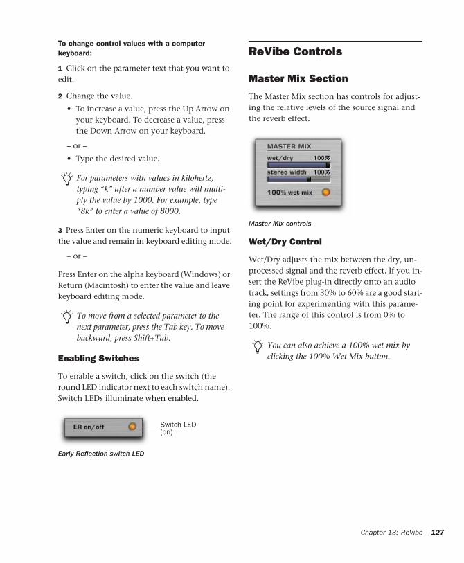
To change control values with a computer keyboard:
1 Click on the parameter text that you want to edit.
2 Change the value.
• To increase a value, press the Up Arrow on your keyboard. To decrease a value, press the Down Arrow on your keyboard.
– or –
• Type the desired value.
3 Press Enter on the numeric keyboard to input the value and remain in keyboard editing mode.
– or –
Press Enter on the alpha keyboard (Windows) or Return (Macintosh) to enter the value and leave keyboard editing mode.
Enabling Switches
To enable a switch, click on the switch (the round LED indicator next to each switch name). Switch LEDs illuminate when enabled.
For parameters with values in kilohertz, typing “k” after a number value will multi-ply the value by 1000. For example, type “8k” to enter a value of 8000.
To move from a selected parameter to the next parameter, press the Tab key. To move backward, press Shift+Tab.
Early Reflection switch LED
Switch LED(on)
ReVibe Controls
Master Mix Section
The Master Mix section has controls for adjust-ing the relative levels of the source signal and the reverb effect.
Wet/Dry Control
Wet/Dry adjusts the mix between the dry, un-processed signal and the reverb effect. If you in-sert the ReVibe plug-in directly onto an audio track, settings from 30% to 60% are a good start-ing point for experimenting with this parame-ter. The range of this control is from 0% to 100%.
Master Mix controls
You can also achieve a 100% wet mix by clicking the 100% Wet Mix button.
Chapter 13: ReVibe 127
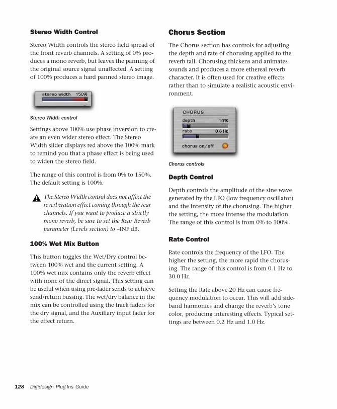
128
Stereo Width Control
Stereo Width controls the stereo field spread of the front reverb channels. A setting of 0% pro-duces a mono reverb, but leaves the panning of the original source signal unaffected. A setting of 100% produces a hard panned stereo image.
Settings above 100% use phase inversion to cre-ate an even wider stereo effect. The Stereo Width slider displays red above the 100% mark to remind you that a phase effect is being used to widen the stereo field.
The range of this control is from 0% to 150%. The default setting is 100%.
100% Wet Mix Button
This button toggles the Wet/Dry control be-tween 100% wet and the current setting. A 100% wet mix contains only the reverb effect with none of the direct signal. This setting can be useful when using pre-fader sends to achieve send/return bussing. The wet/dry balance in the mix can be controlled using the track faders for the dry signal, and the Auxiliary input fader for the effect return.
Stereo Width control
The Stereo Width control does not affect the reverberation effect coming through the rear channels. If you want to produce a strictly mono reverb, be sure to set the Rear Reverb parameter (Levels section) to –INF dB.
Digidesign Plug-Ins Guide
Chorus Section
The Chorus section has controls for adjusting the depth and rate of chorusing applied to the reverb tail. Chorusing thickens and animates sounds and produces a more ethereal reverb character. It is often used for creative effects rather than to simulate a realistic acoustic envi-ronment.
Depth Control
Depth controls the amplitude of the sine wave generated by the LFO (low frequency oscillator) and the intensity of the chorusing. The higher the setting, the more intense the modulation. The range of this control is from 0% to 100%.
Rate Control
Rate controls the frequency of the LFO. The higher the setting, the more rapid the chorus-ing. The range of this control is from 0.1 Hz to 30.0 Hz.
Setting the Rate above 20 Hz can cause fre-quency modulation to occur. This will add side-band harmonics and change the reverb’s tone color, producing interesting effects. Typical set-tings are between 0.2 Hz and 1.0 Hz.
Chorus controls
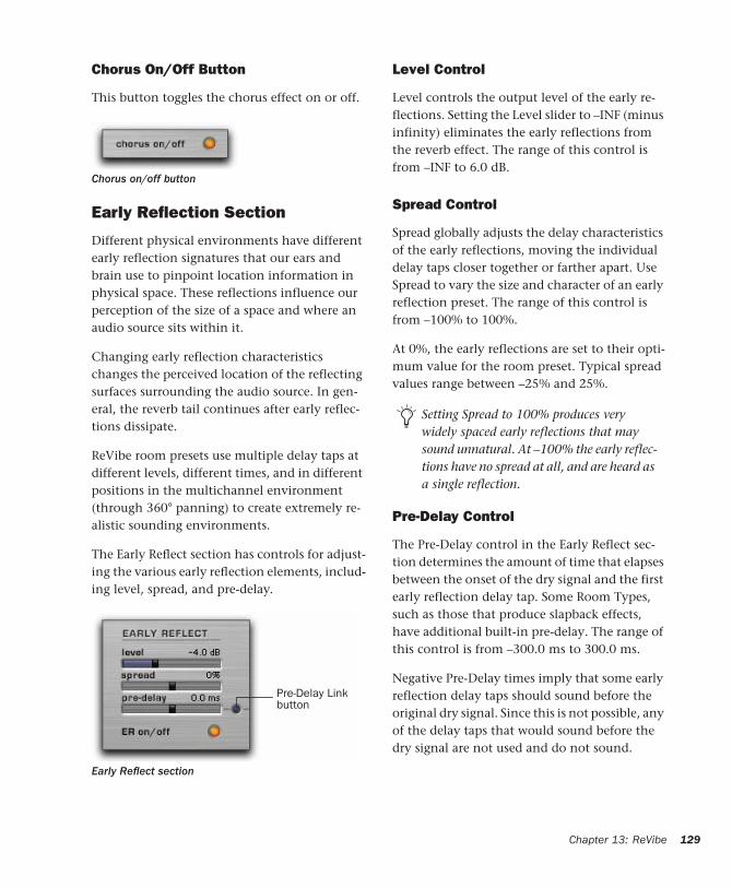
Chorus On/Off Button
This button toggles the chorus effect on or off.
Early Reflection Section
Different physical environments have different early reflection signatures that our ears and brain use to pinpoint location information in physical space. These reflections influence our perception of the size of a space and where an audio source sits within it.
Changing early reflection characteristics changes the perceived location of the reflecting surfaces surrounding the audio source. In gen-eral, the reverb tail continues after early reflec-tions dissipate.
ReVibe room presets use multiple delay taps at different levels, different times, and in different positions in the multichannel environment (through 360° panning) to create extremely re-alistic sounding environments.
The Early Reflect section has controls for adjust-ing the various early reflection elements, includ-ing level, spread, and pre-delay.
Chorus on/off button
Early Reflect section
Pre-Delay Linkbutton
Level Control
Level controls the output level of the early re-flections. Setting the Level slider to –INF (minus infinity) eliminates the early reflections from the reverb effect. The range of this control is from –INF to 6.0 dB.
Spread Control
Spread globally adjusts the delay characteristics of the early reflections, moving the individual delay taps closer together or farther apart. Use Spread to vary the size and character of an early reflection preset. The range of this control is from –100% to 100%.
At 0%, the early reflections are set to their opti-mum value for the room preset. Typical spread values range between –25% and 25%.
Pre-Delay Control
The Pre-Delay control in the Early Reflect sec-tion determines the amount of time that elapses between the onset of the dry signal and the first early reflection delay tap. Some Room Types, such as those that produce slapback effects, have additional built-in pre-delay. The range of this control is from –300.0 ms to 300.0 ms.
Negative Pre-Delay times imply that some early reflection delay taps should sound before the original dry signal. Since this is not possible, any of the delay taps that would sound before the dry signal are not used and do not sound.
Setting Spread to 100% produces very widely spaced early reflections that may sound unnatural. At –100% the early reflec-tions have no spread at all, and are heard as a single reflection.
Chapter 13: ReVibe 129
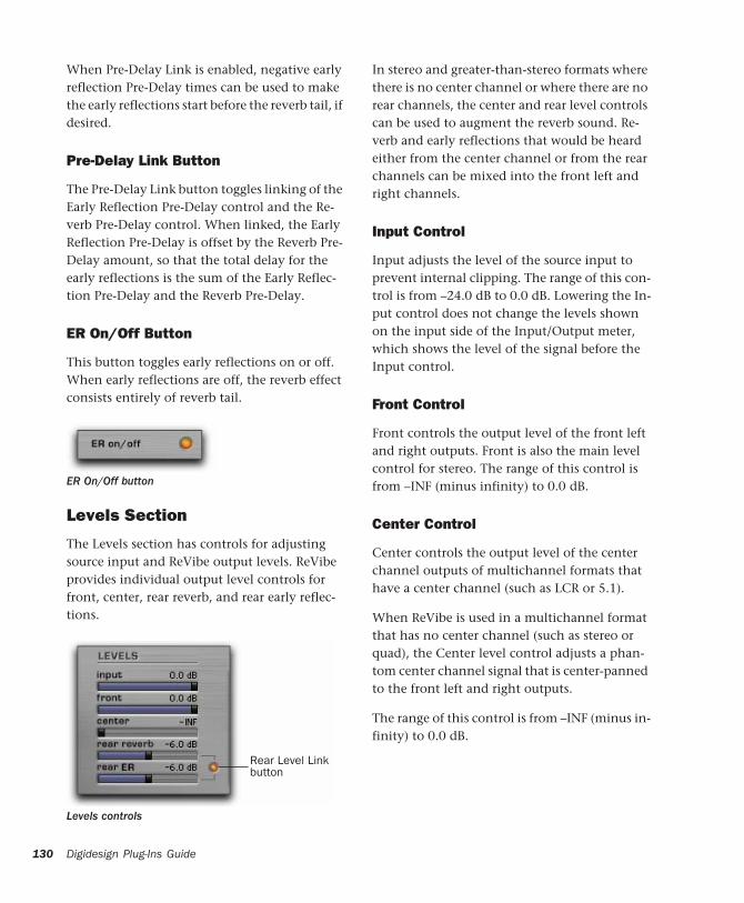
130
When Pre-Delay Link is enabled, negative early reflection Pre-Delay times can be used to make the early reflections start before the reverb tail, if desired.
Pre-Delay Link Button
The Pre-Delay Link button toggles linking of the Early Reflection Pre-Delay control and the Re-verb Pre-Delay control. When linked, the Early Reflection Pre-Delay is offset by the Reverb Pre-Delay amount, so that the total delay for the early reflections is the sum of the Early Reflec-tion Pre-Delay and the Reverb Pre-Delay.
ER On/Off Button
This button toggles early reflections on or off. When early reflections are off, the reverb effect consists entirely of reverb tail.
Levels Section
The Levels section has controls for adjusting source input and ReVibe output levels. ReVibe provides individual output level controls for front, center, rear reverb, and rear early reflec-tions.
ER On/Off button
Levels controls
Rear Level Link button
Digidesign Plug-Ins Guide
In stereo and greater-than-stereo formats where there is no center channel or where there are no rear channels, the center and rear level controls can be used to augment the reverb sound. Re-verb and early reflections that would be heard either from the center channel or from the rear channels can be mixed into the front left and right channels.
Input Control
Input adjusts the level of the source input to prevent internal clipping. The range of this con-trol is from –24.0 dB to 0.0 dB. Lowering the In-put control does not change the levels shown on the input side of the Input/Output meter, which shows the level of the signal before the Input control.
Front Control
Front controls the output level of the front left and right outputs. Front is also the main level control for stereo. The range of this control is from –INF (minus infinity) to 0.0 dB.
Center Control
Center controls the output level of the center channel outputs of multichannel formats that have a center channel (such as LCR or 5.1).
When ReVibe is used in a multichannel format that has no center channel (such as stereo or quad), the Center level control adjusts a phan-tom center channel signal that is center-panned to the front left and right outputs.
The range of this control is from –INF (minus in-finity) to 0.0 dB.
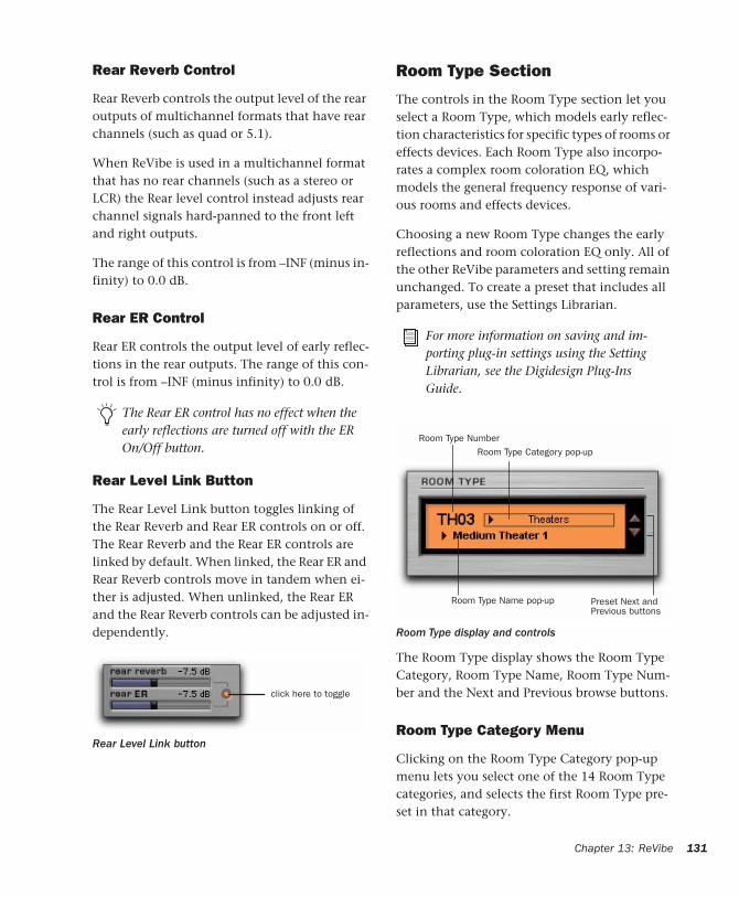
Rear Reverb Control
Rear Reverb controls the output level of the rear outputs of multichannel formats that have rear channels (such as quad or 5.1).
When ReVibe is used in a multichannel format that has no rear channels (such as a stereo or LCR) the Rear level control instead adjusts rear channel signals hard-panned to the front left and right outputs.
The range of this control is from –INF (minus in-finity) to 0.0 dB.
Rear ER Control
Rear ER controls the output level of early reflec-tions in the rear outputs. The range of this con-trol is from –INF (minus infinity) to 0.0 dB.
Rear Level Link Button
The Rear Level Link button toggles linking of the Rear Reverb and Rear ER controls on or off. The Rear Reverb and the Rear ER controls are linked by default. When linked, the Rear ER and Rear Reverb controls move in tandem when ei-ther is adjusted. When unlinked, the Rear ER and the Rear Reverb controls can be adjusted in-dependently.
The Rear ER control has no effect when the early reflections are turned off with the ER On/Off button.
Rear Level Link button
click here to toggle
Room Type Section
The controls in the Room Type section let you select a Room Type, which models early reflec-tion characteristics for specific types of rooms or effects devices. Each Room Type also incorpo-rates a complex room coloration EQ, which models the general frequency response of vari-ous rooms and effects devices.
Choosing a new Room Type changes the early reflections and room coloration EQ only. All of the other ReVibe parameters and setting remain unchanged. To create a preset that includes all parameters, use the Settings Librarian.
The Room Type display shows the Room Type Category, Room Type Name, Room Type Num-ber and the Next and Previous browse buttons.
Room Type Category Menu
Clicking on the Room Type Category pop-up menu lets you select one of the 14 Room Type categories, and selects the first Room Type pre-set in that category.
For more information on saving and im-porting plug-in settings using the Setting Librarian, see the Digidesign Plug-Ins Guide.
Room Type display and controls
Room Type NumberRoom Type Category pop-up
Room Type Name pop-up Preset Next and Previous buttons
Chapter 13: ReVibe 131
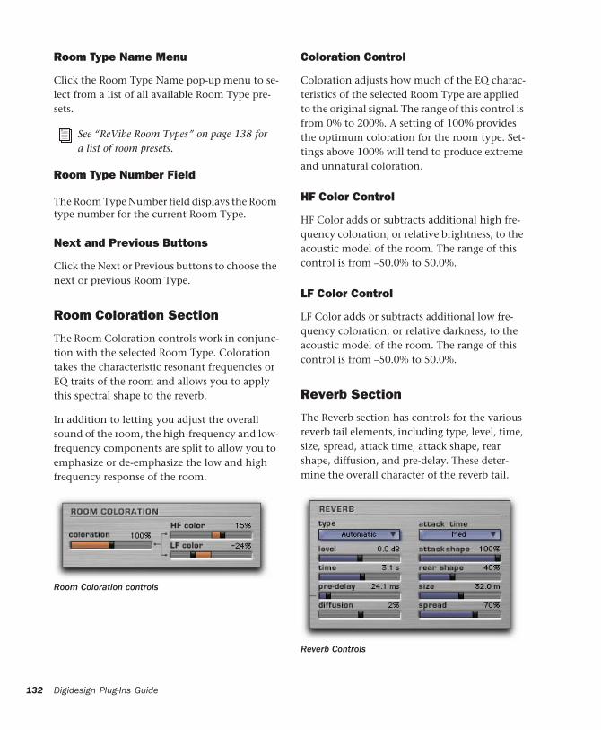
132
Room Type Name Menu
Click the Room Type Name pop-up menu to se-lect from a list of all available Room Type pre-sets.
Room Type Number Field
The Room Type Number field displays the Room type number for the current Room Type.
Next and Previous Buttons
Click the Next or Previous buttons to choose the next or previous Room Type.
Room Coloration Section
The Room Coloration controls work in conjunc-tion with the selected Room Type. Coloration takes the characteristic resonant frequencies or EQ traits of the room and allows you to apply this spectral shape to the reverb.
In addition to letting you adjust the overall sound of the room, the high-frequency and low-frequency components are split to allow you to emphasize or de-emphasize the low and high frequency response of the room.
See “ReVibe Room Types” on page 138 for a list of room presets.
Room Coloration controls
Digidesign Plug-Ins Guide
Coloration Control
Coloration adjusts how much of the EQ charac-teristics of the selected Room Type are applied to the original signal. The range of this control is from 0% to 200%. A setting of 100% provides the optimum coloration for the room type. Set-tings above 100% will tend to produce extreme and unnatural coloration.
HF Color Control
HF Color adds or subtracts additional high fre-quency coloration, or relative brightness, to the acoustic model of the room. The range of this control is from –50.0% to 50.0%.
LF Color Control
LF Color adds or subtracts additional low fre-quency coloration, or relative darkness, to the acoustic model of the room. The range of this control is from –50.0% to 50.0%.
Reverb Section
The Reverb section has controls for the various reverb tail elements, including type, level, time, size, spread, attack time, attack shape, rear shape, diffusion, and pre-delay. These deter-mine the overall character of the reverb tail.
Reverb Controls
Type Menu
Type is a pop-up menu that sets the type of re-verb tail. There are nine basic reverb types, plus the Automatic type. Selecting the Automatic re-verb type will select the type of reverb tail that is stored with the currently selected room type. The reverb types are:
• Automatic selects the reverb tail type stored with the room type.
• Natural is an average reverb tail type with no extreme characteristics.
• Smooth is optimized for large rooms.
• Fast Attack can be useful for plate reverbs.
• Dense is similar to smooth, and can also be good for a plate reverb.
• Tight is good for small to medium rooms.
• Sparse 1 produces sparse early reflections with a high diffusion buildup.
• Sparse 2 can be useful for a spring reverb.
• Wide is a generic large reverb.
• Small is optimized for small rooms.
Level Control
Level controls the output level of the reverb tail. When set to –INF (minus infinity) no reverb tail is heard, and the reverb effect consists entirely of the early reflections (if enabled). The range of this control is from –INF to 6.0 dB.
Time Control
Time controls how long the reverberation con-tinues after the original source signal stops. The range of this control is from 100.0 ms to Inf (in-finity). Setting Time to its maximum value will produce infinite reverberation.
Pre-Delay Control
The Pre-Delay control in the Reverb section sets the amount of time that elapses between signal input and the onset of the reverb tail.
Under natural conditions, the amount of pre-delay depends on the size and construction of the acoustic space and the relative position of the sound source and the listener. Pre-delay at-tempts to duplicate this phenomenon and is used to create a sense of distance and volume within an acoustic space. Extremely long pre-de-lay settings produce effects that are unnatural but sonically interesting.
The range of this control is from 0.0 ms to 300.0 ms.
Diffusion Control
Diffusion controls the rate that the sound den-sity of the reverb tail increases over time. The control ranges between –50% and 50%. At 0%, diffusion is set to an optimal preset value. Posi-tive Diffusion settings create a longer initial buildup of echo density. At negative settings, the buildup of echo density is slower than at the optimal preset value.
Attack Time Control
Attack Time adjusts the length of time between the start of the reverb tail and its peak level. Set-tings are Short, Medium, or Long.
Chapter 13: ReVibe 133
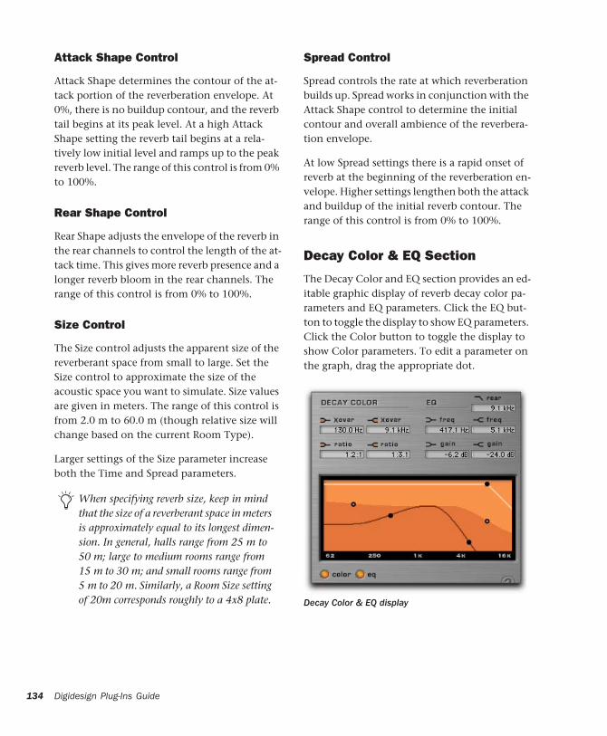
134
Attack Shape Control
Attack Shape determines the contour of the at-tack portion of the reverberation envelope. At 0%, there is no buildup contour, and the reverb tail begins at its peak level. At a high Attack Shape setting the reverb tail begins at a rela-tively low initial level and ramps up to the peak reverb level. The range of this control is from 0% to 100%.
Rear Shape Control
Rear Shape adjusts the envelope of the reverb in the rear channels to control the length of the at-tack time. This gives more reverb presence and a longer reverb bloom in the rear channels. The range of this control is from 0% to 100%.
Size Control
The Size control adjusts the apparent size of the reverberant space from small to large. Set the Size control to approximate the size of the acoustic space you want to simulate. Size values are given in meters. The range of this control is from 2.0 m to 60.0 m (though relative size will change based on the current Room Type).
Larger settings of the Size parameter increase both the Time and Spread parameters.
When specifying reverb size, keep in mind that the size of a reverberant space in meters is approximately equal to its longest dimen-sion. In general, halls range from 25 m to 50 m; large to medium rooms range from 15 m to 30 m; and small rooms range from 5 m to 20 m. Similarly, a Room Size setting of 20m corresponds roughly to a 4x8 plate.
Digidesign Plug-Ins Guide
Spread Control
Spread controls the rate at which reverberation builds up. Spread works in conjunction with the Attack Shape control to determine the initial contour and overall ambience of the reverbera-tion envelope.
At low Spread settings there is a rapid onset of reverb at the beginning of the reverberation en-velope. Higher settings lengthen both the attack and buildup of the initial reverb contour. The range of this control is from 0% to 100%.
Decay Color & EQ Section
The Decay Color and EQ section provides an ed-itable graphic display of reverb decay color pa-rameters and EQ parameters. Click the EQ but-ton to toggle the display to show EQ parameters. Click the Color button to toggle the display to show Color parameters. To edit a parameter on the graph, drag the appropriate dot.
Decay Color & EQ display
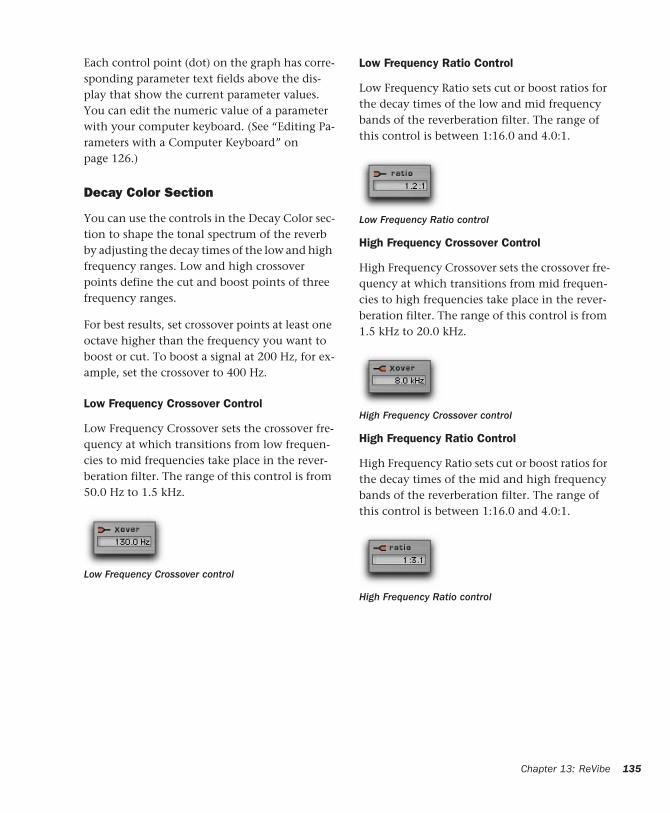
Each control point (dot) on the graph has corre-sponding parameter text fields above the dis-play that show the current parameter values. You can edit the numeric value of a parameter with your computer keyboard. (See “Editing Pa-rameters with a Computer Keyboard” on page 126.)
Decay Color Section
You can use the controls in the Decay Color sec-tion to shape the tonal spectrum of the reverb by adjusting the decay times of the low and high frequency ranges. Low and high crossover points define the cut and boost points of three frequency ranges.
For best results, set crossover points at least one octave higher than the frequency you want to boost or cut. To boost a signal at 200 Hz, for ex-ample, set the crossover to 400 Hz.
Low Frequency Crossover Control
Low Frequency Crossover sets the crossover fre-quency at which transitions from low frequen-cies to mid frequencies take place in the rever-beration filter. The range of this control is from 50.0 Hz to 1.5 kHz.
Low Frequency Crossover control
Low Frequency Ratio Control
Low Frequency Ratio sets cut or boost ratios for the decay times of the low and mid frequency bands of the reverberation filter. The range of this control is between 1:16.0 and 4.0:1.
High Frequency Crossover Control
High Frequency Crossover sets the crossover fre-quency at which transitions from mid frequen-cies to high frequencies take place in the rever-beration filter. The range of this control is from 1.5 kHz to 20.0 kHz.
High Frequency Ratio Control
High Frequency Ratio sets cut or boost ratios for the decay times of the mid and high frequency bands of the reverberation filter. The range of this control is between 1:16.0 and 4.0:1.
Low Frequency Ratio control
High Frequency Crossover control
High Frequency Ratio control
Chapter 13: ReVibe 135
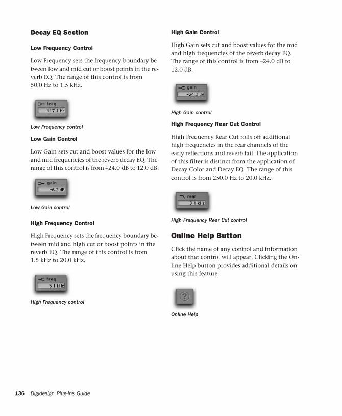
136
Decay EQ Section
Low Frequency Control
Low Frequency sets the frequency boundary be-tween low and mid cut or boost points in the re-verb EQ. The range of this control is from 50.0 Hz to 1.5 kHz.
Low Gain Control
Low Gain sets cut and boost values for the low and mid frequencies of the reverb decay EQ. The range of this control is from –24.0 dB to 12.0 dB.
High Frequency Control
High Frequency sets the frequency boundary be-tween mid and high cut or boost points in the reverb EQ. The range of this control is from 1.5 kHz to 20.0 kHz.
Low Frequency control
Low Gain control
High Frequency control
Digidesign Plug-Ins Guide
High Gain Control
High Gain sets cut and boost values for the mid and high frequencies of the reverb decay EQ. The range of this control is from –24.0 dB to 12.0 dB.
High Frequency Rear Cut Control
High Frequency Rear Cut rolls off additional high frequencies in the rear channels of the early reflections and reverb tail. The application of this filter is distinct from the application of Decay Color and Decay EQ. The range of this control is from 250.0 Hz to 20.0 kHz.
Online Help Button
Click the name of any control and information about that control will appear. Clicking the On-line Help button provides additional details on using this feature.
High Gain control
High Frequency Rear Cut control
Online Help
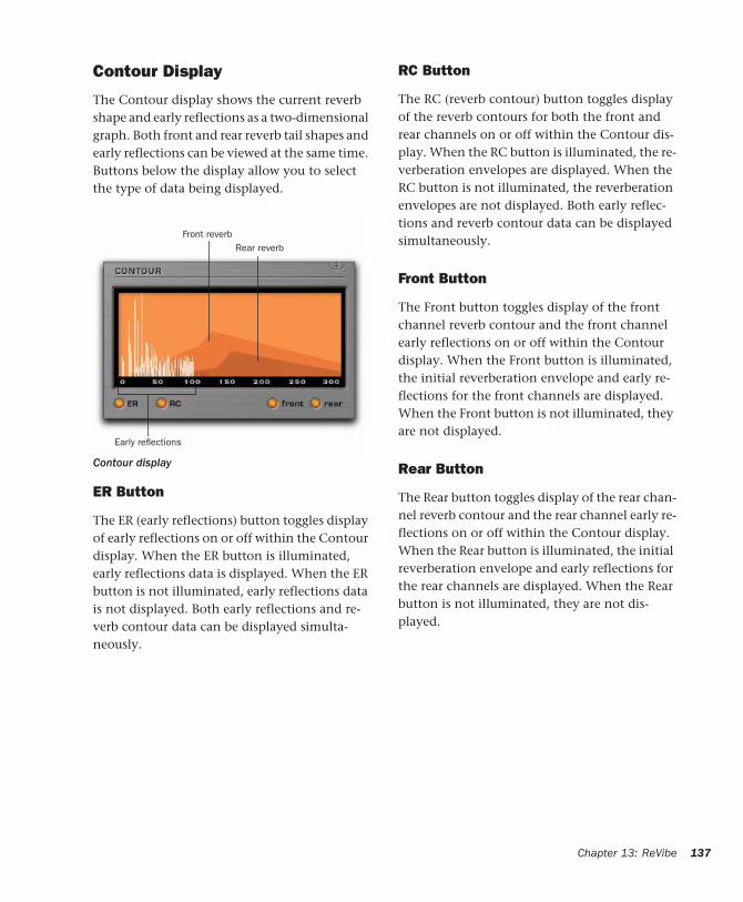
Contour Display
The Contour display shows the current reverb shape and early reflections as a two-dimensional graph. Both front and rear reverb tail shapes and early reflections can be viewed at the same time. Buttons below the display allow you to select the type of data being displayed.
ER Button
The ER (early reflections) button toggles display of early reflections on or off within the Contour display. When the ER button is illuminated, early reflections data is displayed. When the ER button is not illuminated, early reflections data is not displayed. Both early reflections and re-verb contour data can be displayed simulta-neously.
Contour display
Early reflections
Front reverbRear reverb
RC Button
The RC (reverb contour) button toggles display of the reverb contours for both the front and rear channels on or off within the Contour dis-play. When the RC button is illuminated, the re-verberation envelopes are displayed. When the RC button is not illuminated, the reverberation envelopes are not displayed. Both early reflec-tions and reverb contour data can be displayed simultaneously.
Front Button
The Front button toggles display of the front channel reverb contour and the front channel early reflections on or off within the Contour display. When the Front button is illuminated, the initial reverberation envelope and early re-flections for the front channels are displayed. When the Front button is not illuminated, they are not displayed.
Rear Button
The Rear button toggles display of the rear chan-nel reverb contour and the rear channel early re-flections on or off within the Contour display. When the Rear button is illuminated, the initial reverberation envelope and early reflections for the rear channels are displayed. When the Rear button is not illuminated, they are not dis-played.
Chapter 13: ReVibe 137
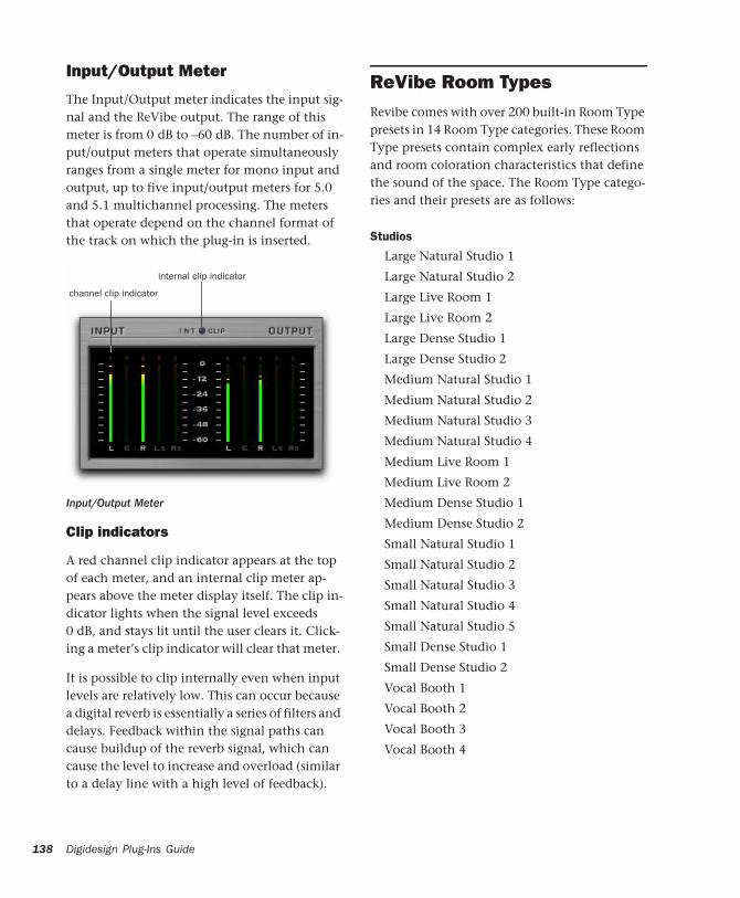
138
Input/Output Meter
The Input/Output meter indicates the input sig-nal and the ReVibe output. The range of this meter is from 0 dB to –60 dB. The number of in-put/output meters that operate simultaneously ranges from a single meter for mono input and output, up to five input/output meters for 5.0 and 5.1 multichannel processing. The meters that operate depend on the channel format of the track on which the plug-in is inserted.
Clip indicators
A red channel clip indicator appears at the top of each meter, and an internal clip meter ap-pears above the meter display itself. The clip in-dicator lights when the signal level exceeds 0 dB, and stays lit until the user clears it. Click-ing a meter’s clip indicator will clear that meter.
It is possible to clip internally even when input levels are relatively low. This can occur because a digital reverb is essentially a series of filters and delays. Feedback within the signal paths can cause buildup of the reverb signal, which can cause the level to increase and overload (similar to a delay line with a high level of feedback).
Input/Output Meter
internal clip indicator
channel clip indicator
Digidesign Plug-Ins Guide
ReVibe Room TypesRevibe comes with over 200 built-in Room Type presets in 14 Room Type categories. These Room Type presets contain complex early reflections and room coloration characteristics that define the sound of the space. The Room Type catego-ries and their presets are as follows:
Studios
Large Natural Studio 1
Large Natural Studio 2
Large Live Room 1
Large Live Room 2
Large Dense Studio 1
Large Dense Studio 2
Medium Natural Studio 1
Medium Natural Studio 2
Medium Natural Studio 3
Medium Natural Studio 4
Medium Live Room 1
Medium Live Room 2
Medium Dense Studio 1
Medium Dense Studio 2
Small Natural Studio 1
Small Natural Studio 2
Small Natural Studio 3
Small Natural Studio 4
Small Natural Studio 5
Small Dense Studio 1
Small Dense Studio 2
Vocal Booth 1
Vocal Booth 2
Vocal Booth 3
Vocal Booth 4
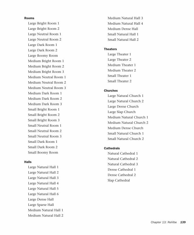
Rooms
Large Bright Room 1
Large Bright Room 2
Large Neutral Room 1
Large Neutral Room 2
Large Dark Room 1
Large Dark Room 2
Large Boomy Room
Medium Bright Room 1
Medium Bright Room 2
Medium Bright Room 3
Medium Neutral Room 1
Medium Neutral Room 2
Medium Neutral Room 3
Medium Dark Room 1
Medium Dark Room 2
Medium Dark Room 3
Small Bright Room 1
Small Bright Room 2
Small Bright Room 3
Small Neutral Room 1
Small Neutral Room 2
Small Neutral Room 3
Small Dark Room 1
Small Dark Room 2
Small Boomy Room
Halls
Large Natural Hall 1
Large Natural Hall 2
Large Natural Hall 3
Large Natural Hall 4
Large Natural Hall 5
Large Natural Hall 6
Large Dense Hall
Large Sparse Hall
Medium Natural Hall 1
Medium Natural Hall 2
Medium Natural Hall 3
Medium Natural Hall 4
Medium Dense Hall
Small Natural Hall 1
Small Natural Hall 2
Theaters
Large Theater 1
Large Theater 2
Medium Theater 1
Medium Theater 2
Small Theater 1
Small Theater 2
Churches
Large Natural Church 1
Large Natural Church 2
Large Dense Church
Large Slap Church
Medium Natural Church 1
Medium Natural Church 2
Medium Dense Church
Small Natural Church 1
Small Natural Church 2
Cathedrals
Natural Cathedral 1
Natural Cathedral 2
Natural Cathedral 3
Dense Cathedral 1
Dense Cathedral 2
Slap Cathedral
Chapter 13: ReVibe 139
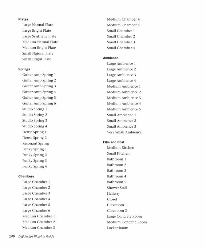
140
Plates
Large Natural Plate
Large Bright Plate
Large Synthetic Plate
Medium Natural Plate
Medium Bright Plate
Small Natural Plate
Small Bright Plate
Springs
Guitar Amp Spring 1
Guitar Amp Spring 2
Guitar Amp Spring 3
Guitar Amp Spring 4
Guitar Amp Spring 5
Guitar Amp Spring 6
Studio Spring 1
Studio Spring 2
Studio Spring 3
Studio Spring 4
Dense Spring 1
Dense Spring 2
Resonant Spring
Funky Spring 1
Funky Spring 2
Funky Spring 3
Funky Spring 4
Chambers
Large Chamber 1
Large Chamber 2
Large Chamber 3
Large Chamber 4
Large Chamber 5
Large Chamber 6
Medium Chamber 1
Medium Chamber 2
Medium Chamber 3
Digidesign Plug-Ins Guide
Medium Chamber 4
Medium Chamber 5
Small Chamber 1
Small Chamber 2
Small Chamber 3
Small Chamber 4
Ambience
Large Ambience 1
Large Ambience 2
Large Ambience 3
Large Ambience 4
Medium Ambience 1
Medium Ambience 2
Medium Ambience 3
Medium Ambience 4
Medium Ambience 5
Small Ambience 1
Small Ambience 2
Small Ambience 3
Very Small Ambience
Film and Post
Medium Kitchen
Small Kitchen
Bathroom 1
Bathroom 2
Bathroom 3
Bathroom 4
Bathroom 5
Shower Stall
Hallway
Closet
Classroom 1
Classroom 2
Large Concrete Room
Medium Concrete Room
Locker Room
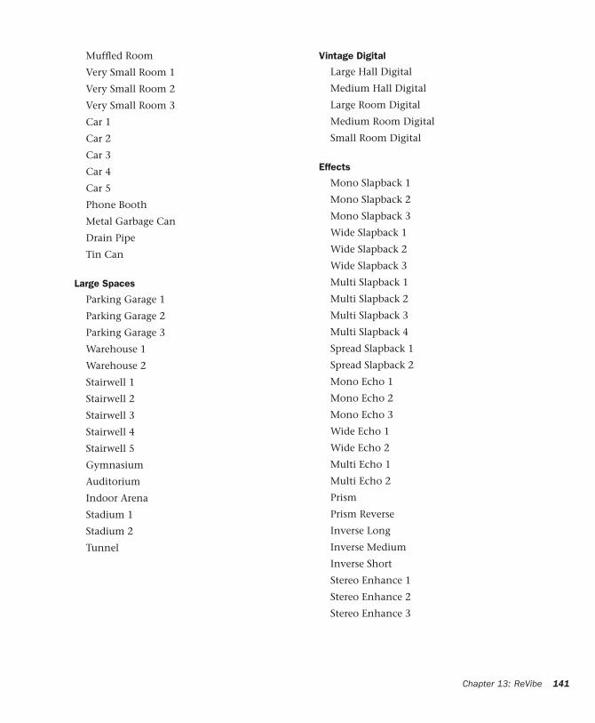
Muffled Room
Very Small Room 1
Very Small Room 2
Very Small Room 3
Car 1
Car 2
Car 3
Car 4
Car 5
Phone Booth
Metal Garbage Can
Drain Pipe
Tin Can
Large Spaces
Parking Garage 1
Parking Garage 2
Parking Garage 3
Warehouse 1
Warehouse 2
Stairwell 1
Stairwell 2
Stairwell 3
Stairwell 4
Stairwell 5
Gymnasium
Auditorium
Indoor Arena
Stadium 1
Stadium 2
Tunnel
Vintage Digital
Large Hall Digital
Medium Hall Digital
Large Room Digital
Medium Room Digital
Small Room Digital
Effects
Mono Slapback 1
Mono Slapback 2
Mono Slapback 3
Wide Slapback 1
Wide Slapback 2
Wide Slapback 3
Multi Slapback 1
Multi Slapback 2
Multi Slapback 3
Multi Slapback 4
Spread Slapback 1
Spread Slapback 2
Mono Echo 1
Mono Echo 2
Mono Echo 3
Wide Echo 1
Wide Echo 2
Multi Echo 1
Multi Echo 2
Prism
Prism Reverse
Inverse Long
Inverse Medium
Inverse Short
Stereo Enhance 1
Stereo Enhance 2
Stereo Enhance 3
Chapter 13: ReVibe 141

142
Digidesign Plug-Ins Guide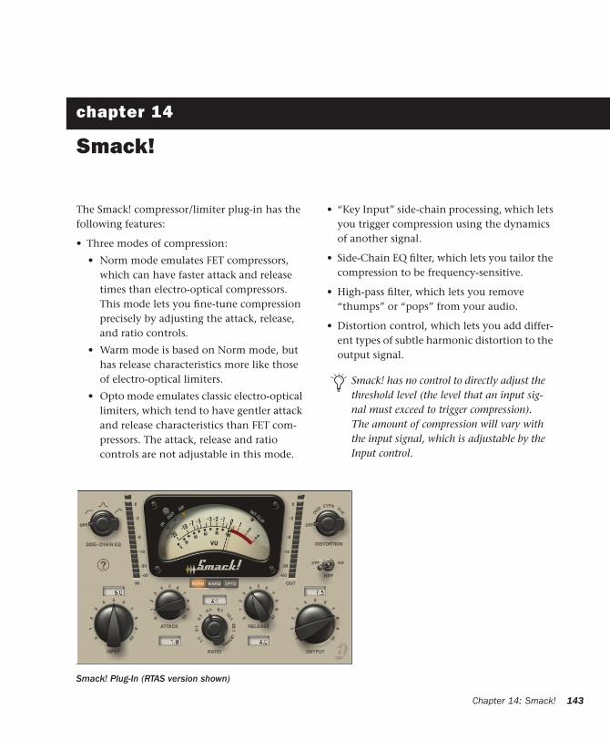
chapter 14
Smack!
The Smack! compressor/limiter plug-in has the following features:
• Three modes of compression:
• Norm mode emulates FET compressors, which can have faster attack and release times than electro-optical compressors. This mode lets you fine-tune compression precisely by adjusting the attack, release, and ratio controls.
• Warm mode is based on Norm mode, but has release characteristics more like those of electro-optical limiters.
• Opto mode emulates classic electro-optical limiters, which tend to have gentler attack and release characteristics than FET com-pressors. The attack, release and ratio controls are not adjustable in this mode.
• “Key Input” side-chain processing, which lets you trigger compression using the dynamics of another signal.
• Side-Chain EQ filter, which lets you tailor the compression to be frequency-sensitive.
• High-pass filter, which lets you remove “thumps” or “pops” from your audio.
• Distortion control, which lets you add differ-ent types of subtle harmonic distortion to the output signal.
Smack! has no control to directly adjust the threshold level (the level that an input sig-nal must exceed to trigger compression). The amount of compression will vary with the input signal, which is adjustable by the Input control.
Smack! Plug-In (RTAS version shown)
Chapter 14: Smack! 143
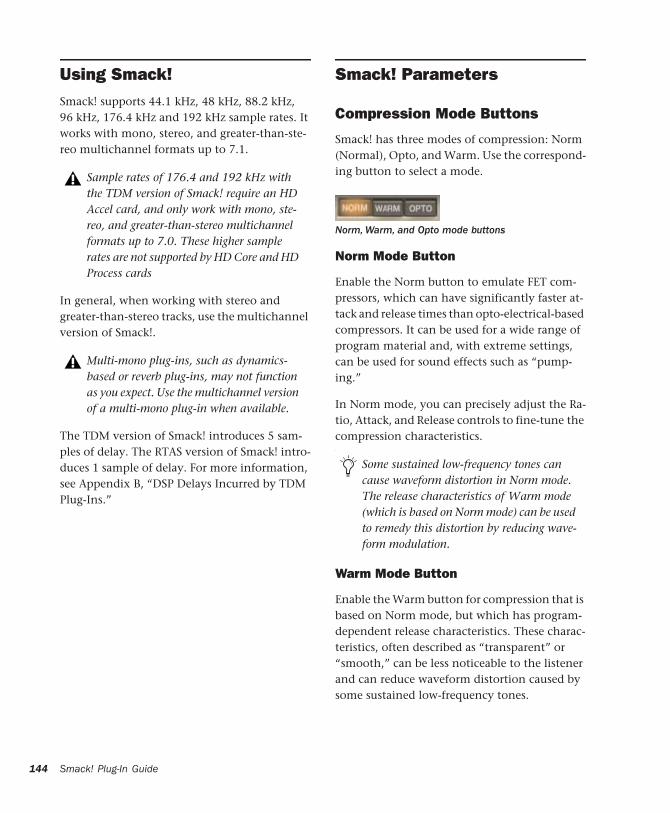
144
Using Smack! Smack! supports 44.1 kHz, 48 kHz, 88.2 kHz, 96 kHz, 176.4 kHz and 192 kHz sample rates. It works with mono, stereo, and greater-than-ste-reo multichannel formats up to 7.1.
In general, when working with stereo and greater-than-stereo tracks, use the multichannel version of Smack!.
The TDM version of Smack! introduces 5 sam-ples of delay. The RTAS version of Smack! intro-duces 1 sample of delay. For more information, see Appendix B, “DSP Delays Incurred by TDM Plug-Ins.”
Sample rates of 176.4 and 192 kHz with the TDM version of Smack! require an HD Accel card, and only work with mono, ste-reo, and greater-than-stereo multichannel formats up to 7.0. These higher sample rates are not supported by HD Core and HD Process cards
Multi-mono plug-ins, such as dynamics-based or reverb plug-ins, may not function as you expect. Use the multichannel version of a multi-mono plug-in when available.
Smack! Plug-In Guide
Smack! Parameters
Compression Mode Buttons
Smack! has three modes of compression: Norm (Normal), Opto, and Warm. Use the correspond-ing button to select a mode.
Norm Mode Button
Enable the Norm button to emulate FET com-pressors, which can have significantly faster at-tack and release times than opto-electrical-based compressors. It can be used for a wide range of program material and, with extreme settings, can be used for sound effects such as “pump-ing.”
In Norm mode, you can precisely adjust the Ra-tio, Attack, and Release controls to fine-tune the compression characteristics. ,
Warm Mode Button
Enable the Warm button for compression that is based on Norm mode, but which has program-dependent release characteristics. These charac-teristics, often described as “transparent” or “smooth,” can be less noticeable to the listener and can reduce waveform distortion caused by some sustained low-frequency tones.
Norm, Warm, and Opto mode buttons
Some sustained low-frequency tones can cause waveform distortion in Norm mode. The release characteristics of Warm mode (which is based on Norm mode) can be used to remedy this distortion by reducing wave-form modulation.
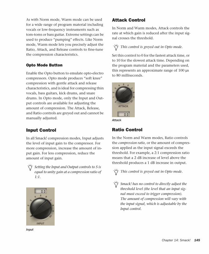
As with Norm mode, Warm mode can be used for a wide range of program material including vocals or low-frequency instruments such as tom-toms or bass guitar. Extreme settings can be used to produce “pumping” effects. Like Norm mode, Warm mode lets you precisely adjust the Ratio, Attack, and Release controls to fine-tune the compression characteristics.
Opto Mode Button
Enable the Opto button to emulate opto-electro compressors. Opto mode produces “soft knee” compression with gentle attack and release characteristics, and is ideal for compressing thin vocals, bass guitars, kick drums, and snare drums. In Opto mode, only the Input and Out-put controls are available for adjusting the amount of compression. The Attack, Release, and Ratio controls are greyed out and cannot be manually adjusted.
Input Control
In all Smack! compression modes, Input adjusts the level of input gain to the compressor. For more compression, increase the amount of in-put gain. For less compression, reduce the amount of input gain.
Setting the Input and Output controls to 5 is equal to unity gain at a compression ratio of 1:1.
Input
Attack Control
In Norm and Warm modes, Attack controls the rate at which gain is reduced after the input sig-nal crosses the threshold.
Set this control to 0 for the fastest attack time, or to 10 for the slowest attack time. Depending on the program material and the parameters used, this represents an approximate range of 100 µs to 80 milliseconds.
Ratio Control
In the Norm and Warm modes, Ratio controls the compression ratio, or the amount of compres-sion applied as the input signal exceeds the threshold. For example, a 2:1 compression ratio means that a 2 dB increase of level above the threshold produces a 1 dB increase in output.
This control is greyed out in Opto mode.
Attack
This control is greyed out in Opto mode.
Smack! has no control to directly adjust the threshold level (the level that an input sig-nal must exceed to trigger compression). The amount of compression will vary with the input signal, which is adjustable by the Input control.
Chapter 14: Smack! 145
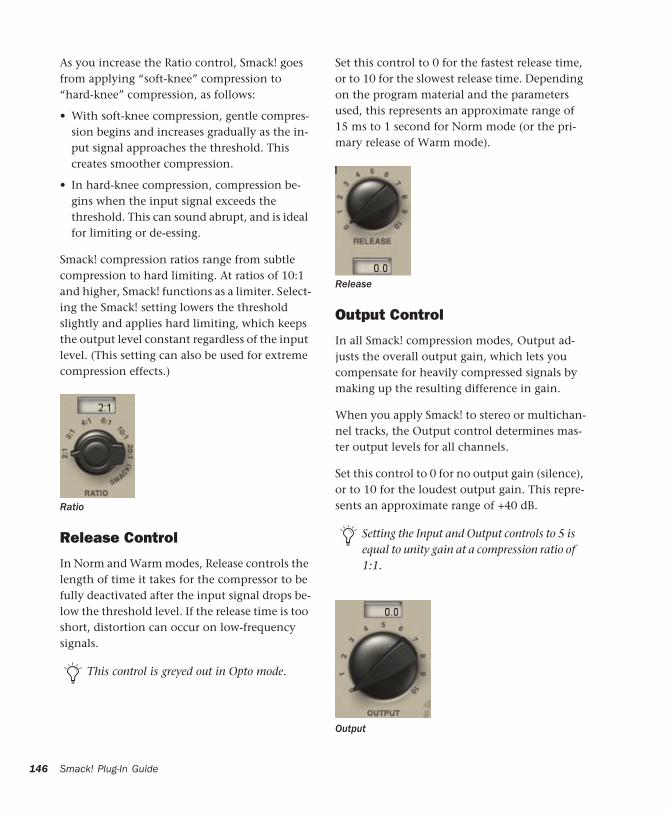
146
As you increase the Ratio control, Smack! goes from applying “soft-knee” compression to “hard-knee” compression, as follows:
• With soft-knee compression, gentle compres-sion begins and increases gradually as the in-put signal approaches the threshold. This creates smoother compression.
• In hard-knee compression, compression be-gins when the input signal exceeds the threshold. This can sound abrupt, and is ideal for limiting or de-essing.
Smack! compression ratios range from subtle compression to hard limiting. At ratios of 10:1 and higher, Smack! functions as a limiter. Select-ing the Smack! setting lowers the threshold slightly and applies hard limiting, which keeps the output level constant regardless of the input level. (This setting can also be used for extreme compression effects.)
Release Control
In Norm and Warm modes, Release controls the length of time it takes for the compressor to be fully deactivated after the input signal drops be-low the threshold level. If the release time is too short, distortion can occur on low-frequency signals.
Ratio
This control is greyed out in Opto mode.
Smack! Plug-In Guide
Set this control to 0 for the fastest release time, or to 10 for the slowest release time. Depending on the program material and the parameters used, this represents an approximate range of 15 ms to 1 second for Norm mode (or the pri-mary release of Warm mode).
Output Control
In all Smack! compression modes, Output ad-justs the overall output gain, which lets you compensate for heavily compressed signals by making up the resulting difference in gain.
When you apply Smack! to stereo or multichan-nel tracks, the Output control determines mas-ter output levels for all channels.
Set this control to 0 for no output gain (silence), or to 10 for the loudest output gain. This repre-sents an approximate range of +40 dB.
Release
Setting the Input and Output controls to 5 is equal to unity gain at a compression ratio of 1:1.
Output
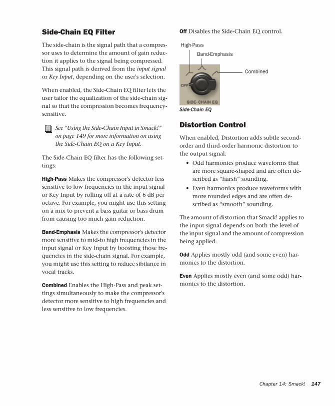
Side-Chain EQ Filter
The side-chain is the signal path that a compres-sor uses to determine the amount of gain reduc-tion it applies to the signal being compressed. This signal path is derived from the input signal or Key Input, depending on the user's selection.
When enabled, the Side-Chain EQ filter lets the user tailor the equalization of the side-chain sig-nal so that the compression becomes frequency-sensitive.
The Side-Chain EQ filter has the following set-tings:
High-Pass Makes the compressor's detector less sensitive to low frequencies in the input signal or Key Input by rolling off at a rate of 6 dB per octave. For example, you might use this setting on a mix to prevent a bass guitar or bass drum from causing too much gain reduction.
Band-Emphasis Makes the compressor's detector more sensitive to mid-to high frequencies in the input signal or Key Input by boosting those fre-quencies in the side-chain signal. For example, you might use this setting to reduce sibilance in vocal tracks.
Combined Enables the High-Pass and peak set-tings simultaneously to make the compressor's detector more sensitive to high frequencies and less sensitive to low frequencies.
See “Using the Side-Chain Input in Smack!” on page 149 for more information on using the Side-Chain EQ on a Key Input.
Off Disables the Side-Chain EQ control.
Distortion Control
When enabled, Distortion adds subtle second-order and third-order harmonic distortion to the output signal.
• Odd harmonics produce waveforms that are more square-shaped and are often de-scribed as “harsh” sounding.
• Even harmonics produce waveforms with more rounded edges and are often de-scribed as “smooth” sounding.
The amount of distortion that Smack! applies to the input signal depends on both the level of the input signal and the amount of compression being applied.
Odd Applies mostly odd (and some even) har-monics to the distortion.
Even Applies mostly even (and some odd) har-monics to the distortion.
Side-Chain EQ
High-Pass
Combined
Band-Emphasis
Chapter 14: Smack! 147
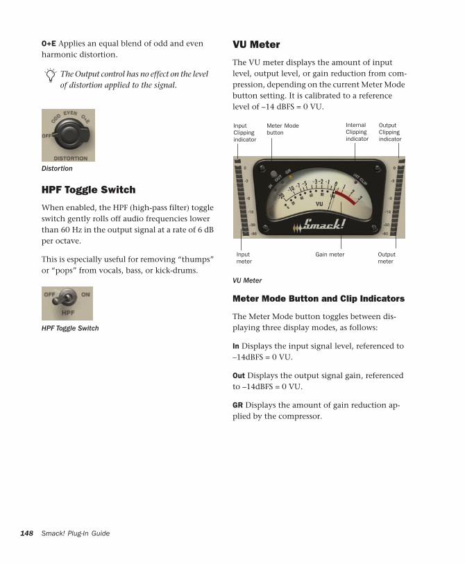
148
O+E Applies an equal blend of odd and even harmonic distortion.
HPF Toggle Switch
When enabled, the HPF (high-pass filter) toggle switch gently rolls off audio frequencies lower than 60 Hz in the output signal at a rate of 6 dB per octave.
This is especially useful for removing “thumps” or “pops” from vocals, bass, or kick-drums.
The Output control has no effect on the level of distortion applied to the signal.
Distortion
HPF Toggle Switch
Smack! Plug-In Guide
VU Meter
The VU meter displays the amount of input level, output level, or gain reduction from com-pression, depending on the current Meter Mode button setting. It is calibrated to a reference level of –14 dBFS = 0 VU.
Meter Mode Button and Clip Indicators
The Meter Mode button toggles between dis-playing three display modes, as follows:
In Displays the input signal level, referenced to –14dBFS = 0 VU.
Out Displays the output signal gain, referenced to –14dBFS = 0 VU.
GR Displays the amount of gain reduction ap-plied by the compressor.
VU Meter
Output meter
Inputmeter
InputClippingindicator
Meter Modebutton
OutputClippingindicator
InternalClippingindicator
Gain meter
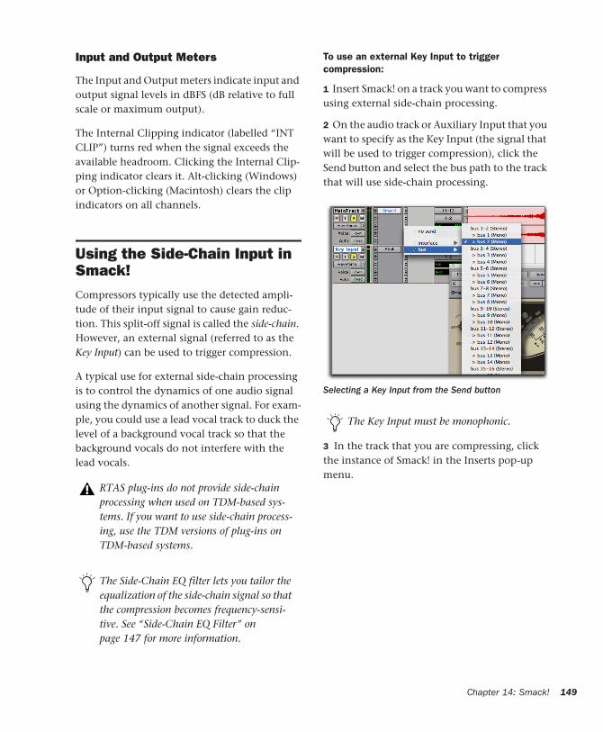
Input and Output Meters
The Input and Output meters indicate input and output signal levels in dBFS (dB relative to full scale or maximum output).
The Internal Clipping indicator (labelled “INT CLIP”) turns red when the signal exceeds the available headroom. Clicking the Internal Clip-ping indicator clears it. Alt-clicking (Windows) or Option-clicking (Macintosh) clears the clip indicators on all channels.
Using the Side-Chain Input in Smack!Compressors typically use the detected ampli-tude of their input signal to cause gain reduc-tion. This split-off signal is called the side-chain. However, an external signal (referred to as the Key Input) can be used to trigger compression.
A typical use for external side-chain processing is to control the dynamics of one audio signal using the dynamics of another signal. For exam-ple, you could use a lead vocal track to duck the level of a background vocal track so that the background vocals do not interfere with the lead vocals.
RTAS plug-ins do not provide side-chain processing when used on TDM-based sys-tems. If you want to use side-chain process-ing, use the TDM versions of plug-ins on TDM-based systems.
The Side-Chain EQ filter lets you tailor the equalization of the side-chain signal so that the compression becomes frequency-sensi-tive. See “Side-Chain EQ Filter” on page 147 for more information.
To use an external Key Input to trigger compression:
1 Insert Smack! on a track you want to compress using external side-chain processing.
2 On the audio track or Auxiliary Input that you want to specify as the Key Input (the signal that will be used to trigger compression), click the Send button and select the bus path to the track that will use side-chain processing.
3 In the track that you are compressing, click the instance of Smack! in the Inserts pop-up menu.
Selecting a Key Input from the Send button
The Key Input must be monophonic.
Chapter 14: Smack! 149
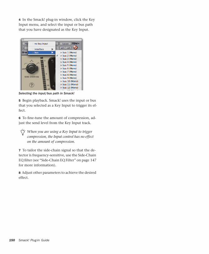
150
4 In the Smack! plug-in window, click the Key Input menu, and select the input or bus path that you have designated as the Key Input.
5 Begin playback. Smack! uses the input or bus that you selected as a Key Input to trigger its ef-fect.
6 To fine-tune the amount of compression, ad-just the send level from the Key Input track.
7 To tailor the side-chain signal so that the de-tector is frequency-sensitive, use the Side-Chain EQ filter (see “Side-Chain EQ Filter” on page 147 for more information).
8 Adjust other parameters to achieve the desired effect.
Selecting the input/bus path in Smack!
When you are using a Key Input to trigger compression, the Input control has no effect on the amount of compression.
Smack! Plug-In Guide
appendix a
DSP Requirements for TDM Plug-Ins
The number of TDM plug-ins you can use at one time depends on how much DSP power is avail-able in your system. Since the TDM hardware on Pro Tools cards provide dedicated DSP for plug-ins, plug-in performance is not limited by CPU processing power.
The DSP tables on the following pages show the theoretical number of instances of each plug-in that can be powered by a single DSP chip on Pro Tools|HD cards. DSP usage differs according to card type.
There are a total of nine DSP chips on a Pro Tools|HD card (HD Core, HD Process, and HD Accel). HD Core and HD Process cards pro-vide identical chip sets. HD Accel cards provide newer, more powerful DSP chips (making the HD Accel card ideal for DSP-intensive plug-ins, and for high sample rate sessions).
DSP tables show the theoretical maximum performance when no other plug-ins or sys-tem tasks (such as I/O) are sharing avail-able DSP resources. You will typically use more than one type of plug-in simulta-neously. The data in these tables are pro-vided as guidelines to help you gauge the relative efficiency of different plug-ins on your system. They are not guaranteed per-formance counts that you should expect to see in typical real-world sessions and usage.
Not all plug-ins are supported on all types of chips. The following tables indicate the number of compatible chips per card.
Using Multi-Mono Plug-Ins on Greater-Than-Stereo Tracks
Plug-ins used in multi-mono format on greater-than-stereo tracks require one mono instance per channel of the multi-channel audio format. For example, a multi-mono plug-in used on a 5.1 format track, requires six mono instances since there are six audio channels in the 5.1 for-mat.
Appendix A: DSP Requirements for TDM Plug-Ins 151
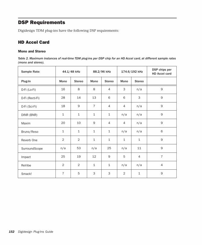
152
DSP RequirementsDigidesign TDM plug-ins have the following DSP requirements:
HD Accel Card
Mono and Stereo
Table 2. Maximum instances of real-time TDM plug-ins per
Digidesign Plug-Ins Guide
DSP chip for an HD Accel card, at different sample rates
(mono and stereo).Sample Rate: 44.1/48 kHz 88.2/96 kHz 174.6/192 kHzDSP chips per HD Accel card
Plug-In Mono Stereo Mono Stereo Mono Stereo
D-Fi (Lo-Fi) 16 8 8 4 3 n/a 9
D-Fi (Recti-Fi) 28 14 13 6 6 3 9
D-Fi (Sci-Fi) 18 9 7 4 4 n/a 9
DINR (BNR) 1 1 1 1 n/a n/a 9
Maxim 20 10 9 4 4 n/a 9
Bruno/Reso 1 1 1 1 n/a n/a 6
Reverb One 2 2 1 1 1 1 9
SurroundScope n/a 53 n/a 25 n/a 11 9
Impact 25 19 12 9 5 4 7
ReVibe 2 2 1 1 n/a n/a 4
Smack! 7 5 3 3 2 1 9
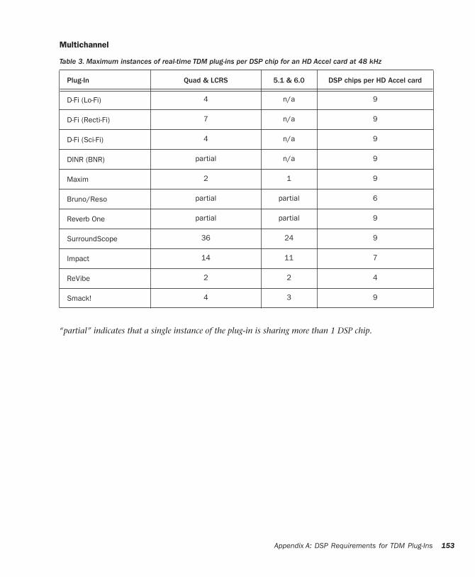
Multichannel
Table 3. Maximum instances of real-time TDM plug-ins per
DSP chip for an HD Accel card at 48 kHz“partial” indicates that a single instance of the plug-in is sharing more than 1 DSP chip.
Plug-In Quad & LCRS 5.1 & 6.0 DSP chips per HD Accel card
D-Fi (Lo-Fi) 4 n/a 9
D-Fi (Recti-Fi) 7 n/a 9
D-Fi (Sci-Fi) 4 n/a 9
DINR (BNR) partial n/a 9
Maxim 2 1 9
Bruno/Reso partial partial 6
Reverb One partial partial 9
SurroundScope 36 24 9
Impact 14 11 7
ReVibe 2 2 4
Smack! 4 3 9
Appendix A: DSP Requirements for TDM Plug-Ins 153
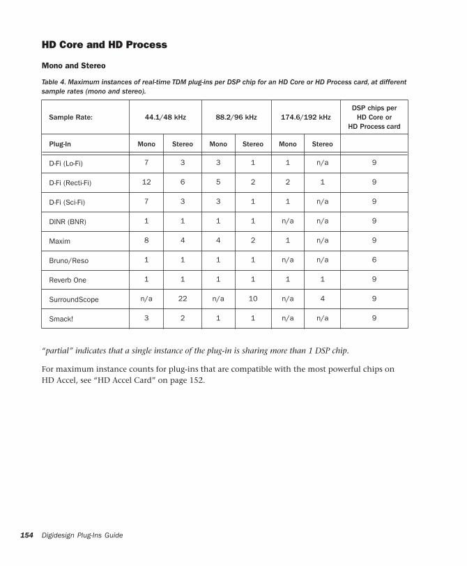
154
HD Core and HD Process
Mono and Stereo
Table 4. Maximum instances of real-time TDM plug-ins per
Digidesign Plug-Ins Guide
DSP chip for an HD Core or HD Process card, at different
“partial” indicates that a single instance of the plug-in is sharing more than 1 DSP chip.
For maximum instance counts for plug-ins that are compatible with the most powerful chips on HD Accel, see “HD Accel Card” on page 152.
sample rates (mono and stereo).
Sample Rate: 44.1/48 kHz 88.2/96 kHz 174.6/192 kHzDSP chips per
HD Core or HD Process card
Plug-In Mono Stereo Mono Stereo Mono Stereo
D-Fi (Lo-Fi) 7 3 3 1 1 n/a 9
D-Fi (Recti-Fi) 12 6 5 2 2 1 9
D-Fi (Sci-Fi) 7 3 3 1 1 n/a 9
DINR (BNR) 1 1 1 1 n/a n/a 9
Maxim 8 4 4 2 1 n/a 9
Bruno/Reso 1 1 1 1 n/a n/a 6
Reverb One 1 1 1 1 1 1 9
SurroundScope n/a 22 n/a 10 n/a 4 9
Smack! 3 2 1 1 n/a n/a 9
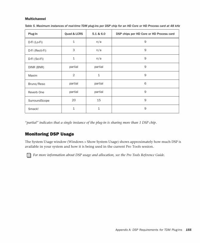
Multichannel
Table 5. Maximum instances of real-time TDM plug-ins per
DSP chip for an HD Core or HD Process card at 48 kHz“partial” indicates that a single instance of the plug-in is sharing more than 1 DSP chip.
Plug-In Quad & LCRS 5.1 & 6.0 DSP chips per HD Core or HD Process card
D-Fi (Lo-Fi) 1 n/a 9
D-Fi (Recti-Fi) 3 n/a 9
D-Fi (Sci-Fi) 1 n/a 9
DINR (BNR) partial partial 9
Maxim 2 1 9
Bruno/Reso partial partial 6
Reverb One partial partial 9
SurroundScope 20 15 9
Smack! 1 1 9
Monitoring DSP Usage
The System Usage window (Windows > Show System Usage) shows approximately how much DSP is available in your system and how it is being used in the current Pro Tools session.
For more information about DSP usage and allocation, see the Pro Tools Reference Guide.
Appendix A: DSP Requirements for TDM Plug-Ins 155

156
Digidesign Plug-Ins Guide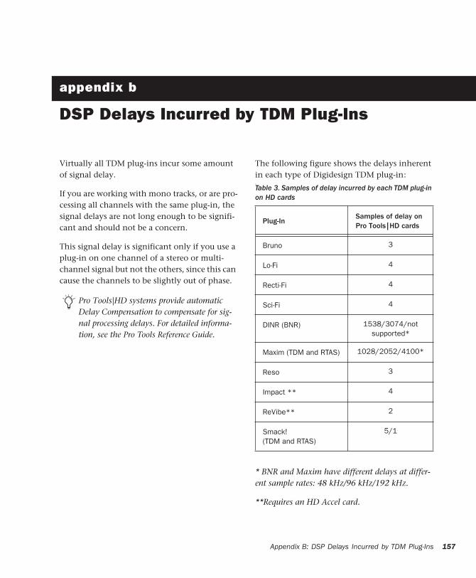
appendix b
DSP Delays Incurred by TDM Plug-Ins
Virtually all TDM plug-ins incur some amount of signal delay.
If you are working with mono tracks, or are pro-cessing all channels with the same plug-in, the signal delays are not long enough to be signifi-cant and should not be a concern.
This signal delay is significant only if you use a plug-in on one channel of a stereo or multi-channel signal but not the others, since this can cause the channels to be slightly out of phase.
Pro Tools|HD systems provide automatic Delay Compensation to compensate for sig-nal processing delays. For detailed informa-tion, see the Pro Tools Reference Guide.
The following figure shows the delays inherent in each type of Digidesign TDM plug-in:≈
* BNR and Maxim have different delays at differ-ent sample rates: 48 kHz/96 kHz/192 kHz.
**Requires an HD Accel card.
Table 3. Samples of delay incurred by each TDM plug-in on HD cards
Plug-InSamples of delay on Pro Tools|HD cards
Bruno 3
Lo-Fi 4
Recti-Fi 4
Sci-Fi 4
DINR (BNR) 1538/3074/not supported*
Maxim (TDM and RTAS) 1028/2052/4100*
Reso 3
Impact ** 4
ReVibe** 2
Smack!(TDM and RTAS)
5/1
Appendix B: DSP Delays Incurred by TDM Plug-Ins 157

158
Digidesign Plug-Ins Guide
Numerics100% Wet control 95100% Wet Mix button 128
Aacoustic environments 93, 124adaptive quantization 47adjusting parameters 126Adjusting ReVibe Parameters 126ADSR Envelope Generator 81, 88aliasing artifacts 47All (harmonics) control 86Alternating Rectification 51Alt-Max Rectification 51Amplitude
controls 81, 87envelope 81
Analyze button 40anechoic chamber 94, 124Anti-Alias Filter control 47Attack 118Attack control 81, 97Attack Shape control 134Attack Time pop-up menu 133Attenuation control 72AudioSuite
AudioSuite Buffer 41buffer size 41multichannel processing 39plug-ins 2plug-ins, using 42processing 43processing preferences 41
AudioSuite processing on networked hard drives 42
Audition pop-up menu 38authorizing plug-ins 6
Auto button 20Auto Fit button 62Auto Update button 105, 107automation
Auto Latch mode 26Auto Touch mode 26creating 26plug-in 25Safe button 20using playlists 25
Automation Safe button 20Auxiliary Inputs
inserting RTAS plug-ins 32
BBand Breakpoints 99band-emphasis frequencies
using to filter compression 147Bend Range control 82, 88bipolar controls 126Bit Resolution control 73Broadband Noise Reduction 57, 59Bruno
controls 79features 75Online Help 84Pitch controls 82Threshold control 80Timbre controls 79using MIDI 77Voice controls 83Voice Stack control 83
buffer size for AudioSuite processing 41Bypass button 38
for real-time plug-ins 19
index
Index 159
160
CCategory 15Ceiling control 72Center control 130Chan/Track Process Mode 37Channel selector 20Chorus On/Off button 129Chorus section 128clip indicator 120, 148
channel 138internal 138
Clip LED 19clipping 19clipping indicator (Reverb One) 101closing multiple plug-in windows 21Coloration control 132Compare button 20compensating for DSP delays 157compression 117
FET-style compression 144filtering frequencies 147limiting (Smack!) 146Norm mode 144side-chain processing 149Smack 143Smack! opto-electrical 145transparent 144using Key Input to trigger 149Warm mode 144
compression ratio 117Contour display 137Contour Line 58, 59
editing 65control points 135Convert Plug-In pop-up 19Copy Settings command 27copying a plug-in setting 29CPU meter 10CPU power requirements for RTAS plug-ins 10CPU Usage Limit 11Create Continuous File command 37Create Individual Files command 37creating a settings subfolder 30Crossfade
control 79, 106frequency 79
Digidesign Plug-Ins Guide
Crossover sliders (Reverb One) 100cross-synthesis 75
DD2
adjusting parameters 23Damping
Damping Amount control 85Damping Velocity control 85
Decay Color and EQ section 134Decay Color section 135Decay control 82Decay EQ section 136Decay Ratio control 96Delay 15delay
DSP induced 12Delay Master control 99Delete Current Settings File command 28Depth control 96, 128destination folder for plug-in settings 28Detune
Detune Amount control 82, 89Detune Velocity control 82, 89
D-Fi demo session 52Diffusion control 97, 133distortion (Smack!) 147Distortion control 147Distortion/Saturation controls 47Dither 15
AudioSuite 41bit depth for AudioSuite 41
Dither control (Maxim) 73down-processing audio 46downward expanders for DINR 58drum limiting 70DSP delay compensation 12DSP delays 157DSP delays inherent in plug-ins 157duplicating inserts 17dynamic audio signal modeling 58dynamic range of a mix 70dynamic range of individual instruments 70Dynamics 15Dynamics controls 95, 107
EEarly Reflect section 129Early Reflection section 129early reflections 94, 124
Early Reflect On 99Early Reflection control 97ER (early reflection) button 100ER Settings control 98presets 98simulating 98
Edit Settings option 41editing parameters
moving to the next field 127with a computer keyboard 126with a mouse 126
Effect Amount control 48Effect Frequency control 49Effects 15effects
recording with 14enabling switches 127Entire Selection mode 37Envelope Follower 49, 90Envelope Generator 81EQ 15ER (early reflections) button 137ER On/Off button 130external audio source, using for side-chain 24External Key 24, 80, 86External On/Off 119external side-chain processing 23
Ffast transients, reducing 144favorites 15File Mode selector 37filtering frequencies for compression 147Fit button 59, 61Follower control 90Freak Mod 48frequencies
filtering to trigger compression 147Frequency control 89, 99Front button 137Front control 130
GGain
Gain Amount control 81, 87Gain Velocity control 81, 87
gain (make-up) 119gain reduction
displaying in VU meter 148Gain Reduction meter 120Glide control 82
Hhard limiting (Smack!) 146hard-knee compression (Smack!) 146Hardware 15Hardware Buffer Size
and latency 11Harmonic 15harmonic distortion
applying to output signal 147harmonic overtones of resonator 85Harmonics control 86HD-series cards
DSP delays 157HF Color control 132High Frequency control 136High Frequency Crossover 135High Frequency Ratio 135High Frequency Rear Cut control 136High Gain control 136high-pass frequencies
using to filter compression 147High-Shelf EQ control 61Histogram 69, 71host processing 2
IiLok 6Impact
meters 120Import Settings command 28importing plug-in settings 29In 145Increment Patch 30Input control 130Input control (Smack!) 145
Index 161
162
Input Level 48Input Level control 71input level meters 101input signal
displaying level of in VU meter 148Input/Output Meter 120Input/Output meter 138Insert Position selector 20inserting plug-ins during playback 17inserts 13
post-disk 14post-fader (Master Faders only) 14pre-fader 14pre-fader operation 14
installing plug-insWindows 5
Instrument 15Internal Clipping indicator (Smack!) 149internal side-chain processing 23
KKey Input 78, 80, 86
Key Input selector 20Smack! 149using to trigger compression 149
key inputdefinition 23using for external side-chain processing 24
Key Input selector 24, 40Key Listen 24Key Listen control 80Key Listen On/Off 119keyboard shortcuts 23
LLatch bar 77late reverberation 94latency
and HW Buffer 11Learn button 61Learn First Audio Mode 61Learn Last Audio Mode 61Level control 96, 98, 129, 133Levels section 130LF Color control 132LFE Enable button 20
Digidesign Plug-Ins Guide
LFO (Low Frequency Oscillator) 49Librarian menu 19License Card 6Limiting
a mixdown 70drums 70individual instruments 70
Linear Quantization control 47Link button 73, 74Link Enable buttons 20linking plug-in controls 22Lissajous Meter 113Load/Unload Sound icons 105Lock Settings File command 28locked regions and AudioSuite processing 42Lo-Fi 45, 46
demo session 54Low Frequency control 136Low Frequency Crossover 135Low Frequency Ratio 135Low Gain control 136Low-Pass Filter control 89
MMake-Up 119make-up gain (Smack!) 146Manufacturer 15Master Faders
inserting RTAS plug-ins 32inserts (post-fader) 14
Master Link button 20Master Mix controls 95Master Mix section 127Master Tune control 82, 88Maxim 69
controls 71Online Help 69peak levels 69signal delay 71signal peaks 70Threshold control 72, 74
Meter Mode button 148meters
clipping indicator 101input 101output 101
MIDIand Bruno/Reso 77MIDI-triggered samplers 103
MIDI Beat Clock 24, 80MIDI Clock control 80, 87Mix control 52, 73, 81, 107Mod Amount/Mod Rate control 50Mod Delay II
Tempo Sync 25Mod Slewing control 49mode 143Modulation 15Modulation Type control 49mono 117mono plug-ins 14Mono voice mode for Reso 83, 90moving inserts 17multichannel 117multichannel formats 113multichannel formats supported 125multichannel plug-ins 14multi-mono plug-ins 14MultiShell II compatible plug-ins 10muted regions and AudioSuite processing 42
Nnegative excursion period of waveform 51Negative Rectification 51Next and Previous Room Type buttons 132Noise Contour line 58Noise Generator 47Noise Reduction 15Noise Reduction Amount control 60Noise Reduction limitations 58Noise Shaping control 73Noise Signature 58, 59non-linear harmonic distortion
applying to output signal 147non-real-time plug-ins 35Norm button 144Normal (see Norm button)
OOdd (harmonics) control 86Online Help button 136
on-screen keyboard 77, 79, 84opening multiple plug-in windows 21Opto
Smack! opto-electrical compression 145ordering RTAS and TDM plug-ins 33Other 15Output control 72Output Level meters 101Output Meter 48, 50, 52output signal
displaying level of in VU meter 148Overwrite File command 37
Pparameters 126
Norm mode 144Warm mode 144
Paste Settings command 28pasting plug-in settings 29Peak Align control 106Peak limiting 69, 70Peak On All Chans/Tracks mode 38Peak On Each Chan/Track mode 38Phase Invert button 20Phase Meter 115Pitch Shift 15Playlist command 36plug-in controls
adjusting 22, 23linking 22
Plug-In selector 19, 36for AudioSuite plug-ins 36
plug-in Settings Librarian 27Plug-In window
closing multiple windows 21opening multiple windows 21
plug-in-induced delays 12plug-ins
as Inserts 13auditioning settings 30automating 25creating a default setting 29inserting 16inserting during playback 17inserting on-the-fly 17Manufacturer view 15
Index 163
164
mono 14moving and duplicating 17multichannel 14multi-mono 14Plug-In selector 35removing 17settings librarian 39
Poly voice mode 83, 90pops, removing with Smack! 148Portamento control 82, 88Positive Excursion 51Positive Rectification 51post-disk inserts 14post-fader inserts 14Post-Filter 51, 52Preamp noise 57Pre-delay 94, 124
presets 97pre-delay 124Pre-Delay control
early reflections 129Pre-Delay Link 130reverb tail 133
Pre-Delay Link button 130pre-fader inserts 14Pre-Filter 50previewing AudioSuite effects 38Process Mode selector 37processing
AudioSuite 39preferences 41requirements of real-time plug-ins 9
QQ control 89Quantization control 47quantization noise 73
RRate control 96, 128Ratio 118RC (reverb contour) button 100, 137real-time plug-ins
AudioSuite 2RTAS and TDM 9
Rear button 137
Digidesign Plug-Ins Guide
Rear ER control 131Rear Level Link button 131Rear Reverb control 131Rear Shape control 134recommended usages
for Norm mode 144for Opto mode 145for Warm mode 144
recording with plug-in effects 14Recti-Fi 46, 50
demo session 55Rectification 51reflection 129Region by Region mode 37Region List command 36Release 118Release control 60, 72, 82Release control (Smack!) 146replacing audio with SoundReplacer 103Reso
controls 84features 76Online Help 91Pitch controls 88Threshold control 86Timbre controls 85Voice controls 89Voice Stack control 90
Resonance (Q) control 89Resonance Amount control 85Resonance Velocity control 85Resonant peak 89Resonator 75, 85Resonator– 48Resonator+ 48Response control 60Reverb 15reverb
character 94reverb graphs
editing 94Reverb Color 99Reverb Contour 100Reverb EQ 99
Reverb OneChorus controls 96HF Cut control 99
HF Damp control 100Online Help 100Threshold control 96Time control 96
Reverb section 132reverb tail 124reverb tail controls 132Reverb tail type 133reverberation
explained 93Reverberation Concepts 124reverberation explained 124ReVibe 123
Chorus section 128Contour Display 137Decay Color & EQ section 134Decay Color section 135Decay EQ section 136Early Reflect section 129Early Reflection section 129Levels section 130Master Mix section 127Reverb section 132Room Coloration section 132Room Type section 131
Ring Mod control 48ring modulation 48room coloration 124Room Coloration section 132Room Type Category menu 131Room Type Name menu 132Room Type Number field 132Room Type section 131Root Settings folder 28
specifying 28RTAS plug-ins 2
additional latency 33improving performance 11limitations on TDM-based systems 149ordering with TDM plug-ins 33placing after TDM plug-ins 32placing on Auxiliary Inputs or Master Faders 32voice usage 33
SSample Rate control 46Sample Size control 47
Sample+Hold control 49saving plug-in settings 29
Save Plug-In Settings To command 28Save Settings As command 27Save Settings command 27
Sci-Fi 45, 48demo session 53
screen response 11Scroll Left/Right buttons 62selecting tracks for AudioSuite processing 42Selection Reference selector 36Set As User Default command 28Set Plug-In Default To command 28Set Root Settings Folder command 28settings 39
choosing a destination for 28copying 29creating subfolders 29creating User Default 29importing 29pasting 29saving 29Settings Preferences command 28
Settings Menu 19shortcuts for keyboard input 23side-chain
definition 23Side-Chain EQ control 147side-chain filters 24
Smack! 147Side-Chain Listen 24side-chain processing 20, 23, 78, 118, 121
Smack! 149using 149
signal delay 157simulating early reflections 98Size control 97, 134Slewing 49Slow Down control 52Smack!
adjusting input 145Attack control 145band emphasis 147clip indicator 149compression modes 144distortion controls 147hard limiting ratio setting 146
Index 165
166
high-pass detector 147high-pass filter 148increasing and decreasing Ratio 145Input meter 149key input 149level 143limiting 146multichannel formats, supported 144Norm mode 144Opto 145output gain 146Output meter 149Ratio control 145reducing waveform distortion, Norm mode 144Release control 146side-chain frequency filters 147side-chain processing 149soft-knee 146supported sample rates 144threshold (definition of) 145threshold and ratio 145unity gain 145
smooth compression 144Smoothing control 60soft-knee compression (Smack!) 146Sound Field 15SoundReplacer
controls 104features 103Online Help 107
Spectral Graph 59Speed Up control 52Spread control 81, 97, 99, 129, 134Stereo spread 81Stereo Width control 95, 128subfolders, creating for settings 29Subharmonic synthesis 52Super Fit button 62supported sample rates 125Surround Display 114SurroundScope
displays 114features 113using 113
Sustain Level control 82Switch control 80System Usage window 155
RTAS 10
Digidesign Plug-Ins Guide
Ttape hiss 57Target button 20TC/E plug-in option 41TDM plug-ins 1, 9, 123
DSP requirements 151inserting on tracks 16moving and duplicating 17ordering with RTAS plug-ins 33removing from tracks 17
tempoTempo Sync 24
Tempo Sync 20, 24Threshold 118threshold 146
definition 143thumps, removing with Smack! 148Timbrometer 80Time control 133Time Trimmer 41TimeAdjuster plug-in
using for delay compensation 12time-slicing 75Toggle (harmonics) control 86Track selector 19transparent compression 144triangle wave 49Trigger
envelope 104markers 104
Trigger and Hold 49Trigger Threshold 105Type pop-up menu 133
UUndo button for DINR 63unity 146unlinking plug-in controls 22Update button 105, 106usages
(see recommended usages)Use in Playlist button 36User Default setting, creating 29
VVari-Fi 46, 52Voice 76Voice Mode control 83voice stacking 89voices
and RTAS 33VU meter 148
Wwah-wah effect 90Warm button 144wave sequencing 79waveform display of SoundReplacer 104waveform distortion
reducing with Warm mode 144Web site 3Wet/Dry control 95, 127
XX axis of histogram 71
YY axis of histogram 71
Zzero crossing 51Zoom Out/In buttons 62Zoomer 104, 106
Index 167

168
Digidesign Plug-Ins Guide