DIGI-IT Users Guidedigi-it.com/pdf/INSTALL-MANUAL.pdfUsers Guide Page 7 of 60 Printed for Reference...
60
Users Guide Page 1 of 60 Printed for Reference Only on October 21, 2010 DIGI-IT INC. Installation Guide Version ID: 4.0.2.1 Date: Sep/14/2010 Author: Digi-IT Inc.
Transcript of DIGI-IT Users Guidedigi-it.com/pdf/INSTALL-MANUAL.pdfUsers Guide Page 7 of 60 Printed for Reference...

Users Guide Page 1 of 60 Printed for Reference Only on October 21, 2010 DIGI-IT INC.
Installation Guide
Version ID: 4.0.2.1
Date: Sep/14/2010
Author: Digi-IT Inc.

Users Guide Page 2 of 60 Printed for Reference Only on October 21, 2010 DIGI-IT INC.
Contents
Installation Guide ............................................................................................................................................. 1
1. Minimum System Requirement (Recommend) ...................................................................................... 3
2. Products .................................................................................................................................................... 4
3. Installation ................................................................................................................................................. 7 3.1. Installation of DIT-4.............................................................................................................................. 7 3.2. Installation of DIT-4 PRO ..................................................................................................................... 8 3.3. Installation of DIT-300, DIT-600, DIT-1200, DIT-2400 Series ............................................................. 9 3.4. Installation of Live Display Board ...................................................................................................... 13 3.5. Installation of DIT-1200Pro ................................................................................................................ 15 3.6. Installation of DIT-2400Pro , DIT-4800Pro and DIT-4800Pro/Ex ...................................................... 16 3.7. Installation of DIT-2400H.Pro ............................................................................................................ 19 3.8. Installation of DIT-2400U.Pro ............................................................................................................ 20 3.9. Installation of DIT-4800U.Pro ............................................................................................................ 21 3.10. Installation of DIT-2400S32 ........................................................................................................... 22 3.11. Installation of DIT-9600 .................................................................................................................. 25 3.12. Installation of Multi-board(Two Board) ........................................................................................... 26 3.13. Installation of 16ch Audio Capture Card ........................................................................................ 29
4. Installation of Capture Board Driver ; DIT-4, DIT-4PRO, DIT-300, DIT-600, DIT-1200, DIT-2400 ..... 30 4.1. Installation of Video Driver ................................................................................................................. 30 4.2. Installation of Audio Driver ................................................................................................................. 31
5. Installation of Live Display Board Driver.............................................................................................. 34
6. Installation of DIT-XXXXPro Board Driver ; DIT-1200Pro, DIT-2400Pro, DIT-4800Pro and DIT-4800Pro/Ex ...................................................................................................................................................... 38
7. Installation of HW Compression Board Driver .................................................................................... 40 7.1. DIT-2400H.Pro ................................................................................................................................... 40 7.2. DIT-2400U.Pro ................................................................................................................................... 44 7.3. DIT-4800U.Pro ................................................................................................................................... 46
8. Installation of 16ch Audio Capture Card Driver ................................................................................... 48 8.1. Installation of Video Driver ................................................................................................................. 48 8.2. Installation of Audio Driver ................................................................................................................. 52
9. Installation of DIT-2400/32S Board Driver ............................................................................................ 57
10. Installation of DIT-9600 Board Driver.................................................................................................... 59

Users Guide Page 3 of 60 Printed for Reference Only on October 21, 2010 DIGI-IT INC.
1. Minimum System Requirement (Recommend)
Product OS CPU Memory VGA
DIT-4
Windows2000/ WindowsXP/ Windows2003/ Vista
P3 - 1.0GHz 256MB 32MB
DIT-4Pro P4 - 2.0GHz 256MB 32MB
DIT-300 P3 - 1.0GHz 256MB 32MB
DIT-600 P3 - 1.4GHz 256MB 32MB
DIT-1200 P4 - 2.0GHz 256MB 32MB
DIT-2400 P4 - 2.4GHz 512MB 32MB
DIT-2400/32S P4 - 3.2GHz 512MB 128MB
DIT-1200Pro P4 - 2.0GHz 512MB 128MB
DIT-2400Pro P4 - 2.8GHz 512MB 128MB
DIT-2400Pro/32D P4 - 3.2Ghz 512MB 128MB
DIT-4800Pro P4 - 3.2Ghz 512MB 128MB
DIT-4800Pro/Ex P4 - 3.2Ghz 512MB PCI Exp. 128 MB
DIT-4800Pro/32D P4 - 3.4Ghz 768MB 128MB
DIT-2400H.Pro P4 - 3.2 GHz 1GB 128MB
DIT-4800H.Pro/16D P4 – 3.4 GHz 1GB 128MB
DIT-2400U.Pro P4 - 3.4 GHz 1GB 128MB
DIT-4800U.Pro/16D Core2 Quad [email protected] 2GB PCI Exp. 256MB
DIT-4800U.Pro Core2 Quad [email protected] 2GB PCI Exp. 256MB
DIT-2400/32D P4 - 3.2GHz 1GB PCI Exp. 128MB
DIT-4800Pro/32D P4 - 3.4Ghz 1GB PCI Exp. 128MB
DIT-4800/64D WindowsXP/ Vista
Core2 6600 2.4GHz 4GB PCI Exp. 256MB
DIT-9600 Core2 Quad [email protected] 4GB PCI Exp. 256 MB
DIT-9600Pro/32D Core2 Quad [email protected] 4GB PCI Exp. 256 MB
- The case which will work in high resolution(640x480), the RAM Memory is 512MB. - The case which will work in 32 Channel, the VGA 64MB must be over. - Recommand Mother Board of Intel chipset and ATI VGA card(32MB over). - Please set ‘Screen Saver’ to ‘None’.(Control Panel->Display->Screen Saver->‘None’) - If you want to use product as follows, system has to have the PCI Expresss slot. : DIT-4800Pro/Ex, DIT-9600 - We recommand that you use XP or Vista for 64ch system (Don’t use Windows2000 and Windows2003 for 64ch system) ; DIT-4800/64D

Users Guide Page 4 of 60 Printed for Reference Only on October 21, 2010 DIGI-IT INC.
2. Products
< DIT-4 > < DIT-4Pro >
< DIT-300 > < DIT-600 >
< DIT-1200 > < DIT-2400 >
< Live Display card > < DIT-1200Pro >

Users Guide Page 5 of 60 Printed for Reference Only on October 21, 2010 DIGI-IT INC.
< DIT-2400Pro > < DIT-4800Pro > < DIT-4800Pro/Ex > < DIT-2400H.Pro > < DIT-2400U.Pro > < DIT-4800U.Pro > < DIT-2400/32S > < DIT-9600 >

Users Guide Page 6 of 60 Printed for Reference Only on October 21, 2010 DIGI-IT INC.
< 16ch Audio Capture Card >

Users Guide Page 7 of 60 Printed for Reference Only on October 21, 2010 DIGI-IT INC.
3. Installation
3.1. Installation of DIT-4
Camera 4
Camera 3
Camera 2
Camera 1
TV Out
Reset(Watchdog)
Sensor & Relay (Digital I/O)
20pin Flat Cable
R
ES
ET
Connect to
Mainboard
<Capture Card>
<Sensor I/O Card>
Relay Outputs
Sensor Inputs
RS485 Cable
Connect to Serial Port
of Mainboard
9DSUB-RJ11 Connector
reset switch cable of system case

Users Guide Page 8 of 60 Printed for Reference Only on October 21, 2010 DIGI-IT INC.
3.2. Installation of DIT-4 PRO
Camera 4
Camera 3
Camera 2
Camera 1
TV Out
Reset(Watchdog)
RE
SET
Sensor & Relay
(Digital I/O)
<Capture Card>
Connect to
Mainboard
reset switch cable of system case
20 pin Flat Cable
I/O Card
Relay Outputs Sensor Inputs
RS485 Cable
9DSUB-RJ11 Connector
Connect to Serial Port
of Mainboard
4CH Audio Card
5 pin Audio Cable

Users Guide Page 9 of 60 Printed for Reference Only on October 21, 2010 DIGI-IT INC.
3.3. Installation of DIT-300, DIT-600, DIT-1200, DIT-2400 Series
Video I/O
9x2 pin 8x2 pin
Black
White
Reset (Watchdog)
RE
SET
Sensor & Relay
(Digital I/O)
26 pin Flat Cable
<Capture Card>
RS485 Cable
9DSUB-RJ11 Connector
Connect to
Mainboard
reset switch cable of system case
Connect to Serial Port
of Mainboard
To : a) BNC Panel
or
b) BNC Cable
To : a) BNC Panel or
b) BNC Cable or
c) 16ch DI/4ch DO Baord
4CH Audio Cable(Only DIT-1200)
8CH Audio Cable(Only DIT-2400)

Users Guide Page 10 of 60 Printed for Reference Only on October 21, 2010 DIGI-IT INC.
a) Video input by BNC I/O Panel
N/A
8x2 pin 9x2 pin
TV Out
White
Black
Sensor & Relay
(Digital I/O)
26 pin Flat Cable
16CH BNC Panel Front
16CH BNC Panel Rear
From Capture Board
From Capture Board
Users Guide Page 11 of 60 Printed for Reference Only on October 21, 2010 DIGI-IT INC.
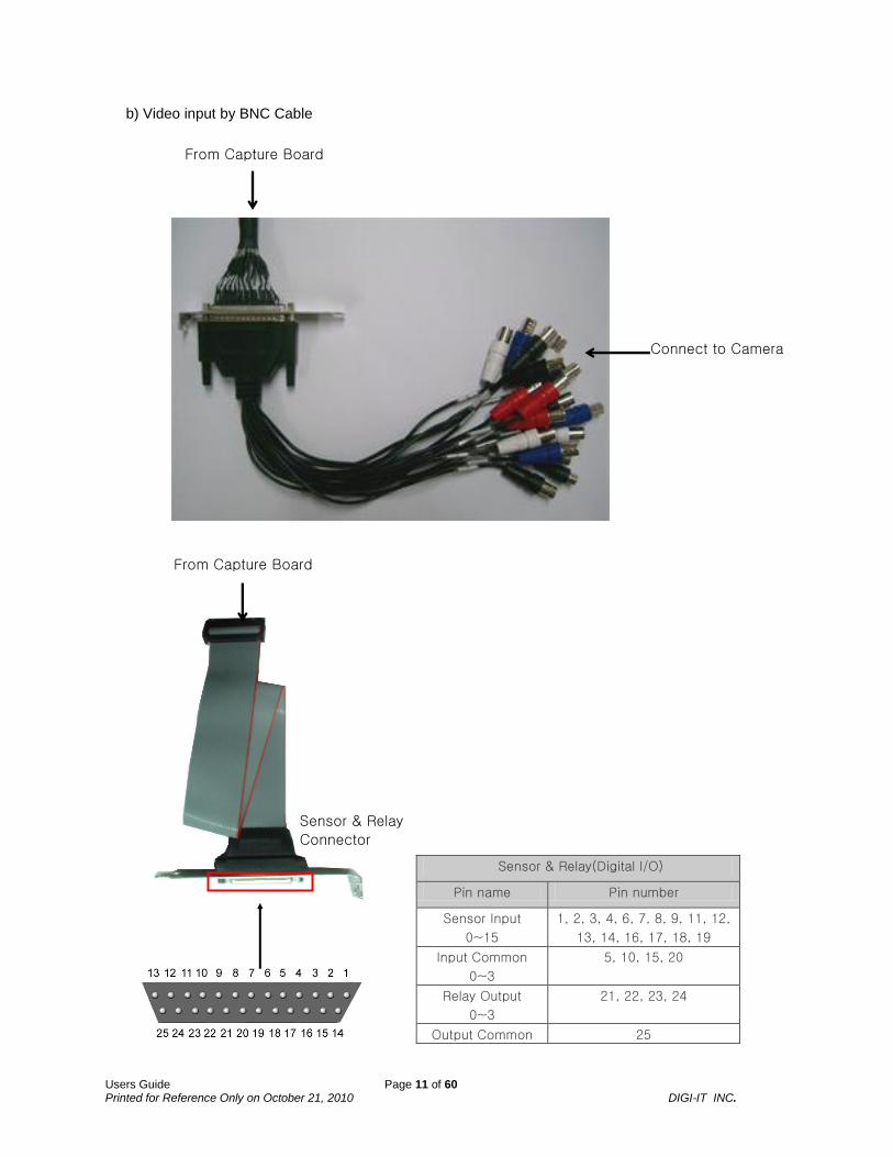
b) Video input by BNC Cable
From Capture Board
Connect to Camera
Sensor & Relay
Connector
From Capture Board
Sensor & Relay(Digital I/O)
Pin name Pin number
Sensor Input
0~15
1, 2, 3, 4, 6, 7, 8, 9, 11, 12,
13, 14, 16, 17, 18, 19
Input Common
0~3
5, 10, 15, 20
Relay Output
0~3
21, 22, 23, 24
Output Common 25

Users Guide Page 12 of 60 Printed for Reference Only on October 21, 2010 DIGI-IT INC.
c) 16ch DI/4ch DO Baord(Option Part)
4ch I/O Card 12ch Sensor Input Card
Relay Outputs Sensor Inputs
From Capture Board
26 pin Flat Cable

Users Guide Page 13 of 60 Printed for Reference Only on October 21, 2010 DIGI-IT INC.
3.4. Installation of Live Display Board
(Connection between capture board and live display board.)
34 pin
Video inputs (ref. 3.3)
<Video Capture Board>
To Live Display Board
34 pin Flat Cable

Users Guide Page 14 of 60 Printed for Reference Only on October 21, 2010 DIGI-IT INC.
<Live Display Board>
From Capture Board
34 pin
34 pin Flat Cable

Users Guide Page 15 of 60 Printed for Reference Only on October 21, 2010 DIGI-IT INC.
3.5. Installation of DIT-1200Pro
120/480 Capture & Live Card
Sensor & Relay (Digital I/O)
20 pin Flat Cable
8CH Video Cable 2ea
TV Out
25DSUB-None
Connect to Serial Port of Mainboard
Sensor & Relay(Digital I/O)
Pin name Pin number
Sensor Input
0~15
1, 2, 3, 4, 6, 7, 8, 9, 11, 12,
13, 14, 16, 17, 18, 19
Input Common
0~3
5, 10, 15, 20
Relay Output
0~3
21, 22, 23, 24
Output Common 25
16CH Audio Card
8CH Audio Cable 2ea
5 pin Audio Cable 4ea
RS485 Cable
Reset (Watchdog)

Users Guide Page 16 of 60 Printed for Reference Only on October 21, 2010 DIGI-IT INC.
3.6. Installation of DIT-2400Pro , DIT-4800Pro and DIT-4800Pro/Ex
a) Video input by BNC Cable
480/480 Capture & Live Card
Sensor & Relay (Digital I/O)
20 pin Flat Cable
8CH Video Cable 2ea
TV Out
25DSUB-None
Connect to Serial Port of Mainboard
Sensor & Relay(Digital I/O)
Pin name Pin number
Sensor Input
0~15
1, 2, 3, 4, 6, 7, 8, 9, 11, 12,
13, 14, 16, 17, 18, 19
Input Common
0~3
5, 10, 15, 20
Relay Output
0~3
21, 22, 23, 24
Output Common 25
Reset (Watchdog)
16CH Audio Card
8CH Audio Cable 2ea
5 pin Audio Cable 4ea
RS485 Cable
If you install 4800Pro/Ex card, you have to connect DC 5V input cable at this connector!!!
DC 5V input cable from power

Users Guide Page 17 of 60 Printed for Reference Only on October 21, 2010 DIGI-IT INC.
b) Video input by BNC I/O Panel(DIT-1200Pro card also)
480/480 Capture & Live Card
Sensor & Relay (Digital I/O)
20 pin Flat Cable
TV Out
Connect to Serial Port of Mainboard
16CH Audio Card
8CH Audio Cable 2ea
5 pin Audio Cable 4ea
RS485 Cable
40 pin
To BNC Panel
26 pin Flat Cable
To BNC Panel
If you install 4800Pro/Ex card, you have to connect DC 5V input cable at this connector!!!
DC 5V input cable from power

Users Guide Page 18 of 60 Printed for Reference Only on October 21, 2010 DIGI-IT INC.
N/A
17x2 pin
White
Black
Sensor & Relay (Digital I/O)
26 pin Flat Cable
16CH BNC Panel Front
16CH BNC Panel Rear
From Capture Board
From Sensor Board

Users Guide Page 19 of 60 Printed for Reference Only on October 21, 2010 DIGI-IT INC.
3.7. Installation of DIT-2400H.Pro
<8ch HW Compression Card>
Sensor & Relay
(Digital I/O)
20 pin Flat Cable
4ch Video/4ch Audio Cable 2ea
TV Out
25DSUB-None
Connect to Serial Port
of Mainboard
Sensor & Relay(Digital I/O)
Pin name Pin number
Sensor Input
0~15
1, 2, 3, 4, 6, 7, 8, 9, 11, 12,
13, 14, 16, 17, 18, 19
Input Common
0~3
5, 10, 15, 20
Relay Output
0~3
21, 22, 23, 24
Output Common 25
Reset (Watchdog)
RS485 Cable

Users Guide Page 20 of 60 Printed for Reference Only on October 21, 2010 DIGI-IT INC.
3.8. Installation of DIT-2400U.Pro
<8ch HW Compression Card>
Sensor & Relay
(Digital I/O)
20 pin Flat Cable
4ch Video/4ch Audio Cable 2ea
TV Out
25DSUB-None
Connect to Serial Port
of Mainboard
Sensor & Relay(Digital I/O)
Pin name Pin number
Sensor Input
0~15
1, 2, 3, 4, 6, 7, 8, 9, 11, 12,
13, 14, 16, 17, 18, 19
Input Common
0~3
5, 10, 15, 20
Relay Output
0~3
21, 22, 23, 24
Output Common 25
Reset (Watchdog)
RS485 Cable

Users Guide Page 21 of 60 Printed for Reference Only on October 21, 2010 DIGI-IT INC.
3.9. Installation of DIT-4800U.Pro
<16ch HW Compression Card>
Sensor & Relay
(Digital I/O)
20 pin Flat Cable
16ch Video Cable
25DSUB-None
Connect to Serial Port
of Mainboard
Sensor & Relay(Digital I/O)
Pin name Pin number
Sensor Input
0~15
1, 2, 3, 4, 6, 7, 8, 9, 11, 12,
13, 14, 16, 17, 18, 19
Input Common
0~3
5, 10, 15, 20
Relay Output
0~3
21, 22, 23, 24
Output Common 25
Reset (Watchdog)
RS485 Cable
16ch Audio Cable
You have to connect DC 5V SATA input cable at this connector!!!
DC 5V SATA input cable from power
16CH Audio Card
8CH Audio Cable 2ea

Users Guide Page 22 of 60 Printed for Reference Only on October 21, 2010 DIGI-IT INC.
3.10. Installation of DIT-2400S32
Sensor & Relay
(Digital I/O)
20 pin Flat Cable
Reset (Watchdog)
16CH Audio Card
8CH Audio Cable 2ea
5 pin Audio Cable 4ea
16CH Video Cable 2ea
<32ch Capture Card>
To : a) 16ch Sensor I/O Card or
b) Extendable 16ch Sensor I/O Card

Users Guide Page 23 of 60 Printed for Reference Only on October 21, 2010 DIGI-IT INC.
a) 16ch Sensor I/O Card
Connect to Serial Port of Mainboard
Sensor & Relay(Digital I/O)
Pin name Pin number
Sensor Input
0~15
1, 2, 3, 4, 6, 7, 8, 9, 11, 12,
13, 14, 16, 17, 18, 19
Input Common
0~3
5, 10, 15, 20
Relay Output
0~3
21, 22, 23, 24
Output Common 25
RS485 Cable
25DSUB-None
From Capture Board

Users Guide Page 24 of 60 Printed for Reference Only on October 21, 2010 DIGI-IT INC.
b) Extendable 16ch Sensor I/O Card(16+16=32ch)
connect to serial Port of mainboard
Sensor & Relay(Digital I/O)
Pin name Pin number
Sensor Input
0~15
1, 2, 3, 4, 6, 7, 8, 9, 11, 12,
13, 14, 16, 17, 18, 19
Input Common
0~3
5, 10, 15, 20
Relay Output
0~3
21, 22, 23, 24
Output Common 25
RS485 Cable 25DSUB-None
From Capture Board
20 pin Flat Cable

Users Guide Page 25 of 60 Printed for Reference Only on October 21, 2010 DIGI-IT INC.
3.11. Installation of DIT-9600
480/480 Capture & Live Card
Sensor & Relay (Digital I/O)
20 pin Flat Cable
Connect to Serial Port of Mainboard
Sensor & Relay(Digital I/O)
Pin name Pin number
Sensor Input
0~15
1, 2, 3, 4, 6, 7, 8, 9, 11, 12,
13, 14, 16, 17, 18, 19
Input Common
0~3
5, 10, 15, 20
Relay Output
0~3
21, 22, 23, 24
Output Common 25
16CH Audio Card
8CH Audio Cable 2ea
5 pin Audio Cable 4ea
RS485 Cable
If you install 4800Pro/Ex card, you have to connect DC 5V input cable at this connector!!!
DC 5V input cable from power
16CH Video Cable 2ea
Reset (Watchdog)

Users Guide Page 26 of 60 Printed for Reference Only on October 21, 2010 DIGI-IT INC.
3.12. Installation of Multi-board(Two Board)
If you install two board with DVR cards you can get 8ch or 16ch or 32ch. - We don’t recommend combination that is not of the same cards. E.g. DIT-4+DIT1200, DIT-300+DIT-600 etc… - The following does not support this feature Support DIT-4, 4Pro, 300, 600, 1200, 2400/32S, 1200Pro, 2400Pro, 4800Pro/Ex, 2400H.Pro,
2400U.Pro, 4800U.Pro Not support DIT-2400, DIT-9600, DIT-Pro, DIT-4800Pro
Remark :
- Please run File Manager and make new DB .(refer to section-2 into User manual ) - If you install two 16 ch cards, you can use 32 ch of sensor but 4 relay out put from 1
st board.
- If you use ‘Watchdog’ , please connect the cable with 1st board.
order
1st camera cable
2nd camera cable
1st board
2nd board (1~16)
(17~32)
change to 32

Users Guide Page 27 of 60 Printed for Reference Only on October 21, 2010 DIGI-IT INC.
< Video Cascade Connection on multi card ; DIT-4800H.Pro/16D and DIT-4800U.Pro/16D > - You have to connect 6pin cable between ‘1
st card video Inputs’ and ‘2
nd card video outputs’
DIT-2400H.Pro or DIT-2400U.Pro
TV Out
1st card
2nd card
Digital Cascade Video Inputs/Outputs
1st card
2nd card
12pin connector for the digital cascade

Users Guide Page 28 of 60 Printed for Reference Only on October 21, 2010 DIGI-IT INC.
- You have to connect 3pin cable between ‘1
st card video Inputs’ and ‘2
nd card video outputs’
* You can also refer to ‘system setting - CCTV’ section in user manual for using this feature.
Analog Cascade Video Inputs/Outputs
1st card
2nd card
6pin connector for the analog cascade

Users Guide Page 29 of 60 Printed for Reference Only on October 21, 2010 DIGI-IT INC.
3.13. Installation of 16ch Audio Capture Card
25DSUB-None
8CH Audio Cable 2ea
<16ch Audio Capture Card>

Users Guide Page 30 of 60 Printed for Reference Only on October 21, 2010 DIGI-IT INC.
4. Installation of Capture Board Driver ; DIT-4, DIT-4PRO, DIT-300, DIT-600, DIT-1200, DIT-2400
4.1. Installation of Video Driver
1. Power on after installation of the capture board on the system.
2. System will recognize each capture board.
3. Select the folder of driver. (inside the provided CD)
4. Complete installation of the driver(s).
Users Guide Page 31 of 60 Printed for Reference Only on October 21, 2010 DIGI-IT INC.
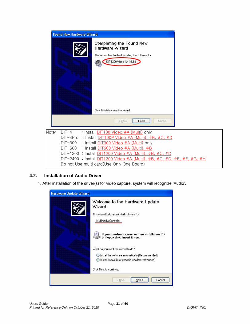
4.2. Installation of Audio Driver
1. After installation of the driver(s) for video capture, system will recognize ‘Audio’.
Note: DIT-4 : Install DIT100 Video #A (Multi) only
DIT-4Pro : Install DIT100P Video #A (Multi), #B, #C, #D
DIT-300 : Install DIT300 Video #A (Multi) only
DIT-600 : Install DIT600 Video #A (Multi), #B
DIT-1200 : Install DIT1200 Video #A (Multi), #B, #C, #D
DIT-2400 : Install DIT1200 Video #A (Multi), #B, #C, #D, #E, #F, #G, #H
Do not Use multi card(Use Only One Board)

Users Guide Page 32 of 60 Printed for Reference Only on October 21, 2010 DIGI-IT INC.
2. Select the folder of driver. (inside the provided CD)
3. Complete installation of the driver(s)
Note: DIT-4 : Install DIT100 Audio #A (Multi) only
DIT-4Pro : Install DIT100P Audio #A (Multi), #B, #C, #D
DIT-300 : Install DIT300 Audio #A (Multi) only
DIT-600 : Install DIT600 Audio #A (Multi), #B
DIT-1200 : Install DIT1200 Audio #A (Multi), #B, #C, #D
DIT-2400 : Install DIT1200 Audio #A (Multi), #B, #C, #D, #E, #F, #G, #H
Do not Use multi card(Use Only One Board)

Users Guide Page 33 of 60 Printed for Reference Only on October 21, 2010 DIGI-IT INC.
4. After installation of the drivers for Video & Audio, you can confirm correct installation of the drivers by run of the ‘Device Manager’ as follows.
In this case that Installed DIT-1200 x 2ea
1st Card
2nd
Card
Users Guide Page 34 of 60 Printed for Reference Only on October 21, 2010 DIGI-IT INC.
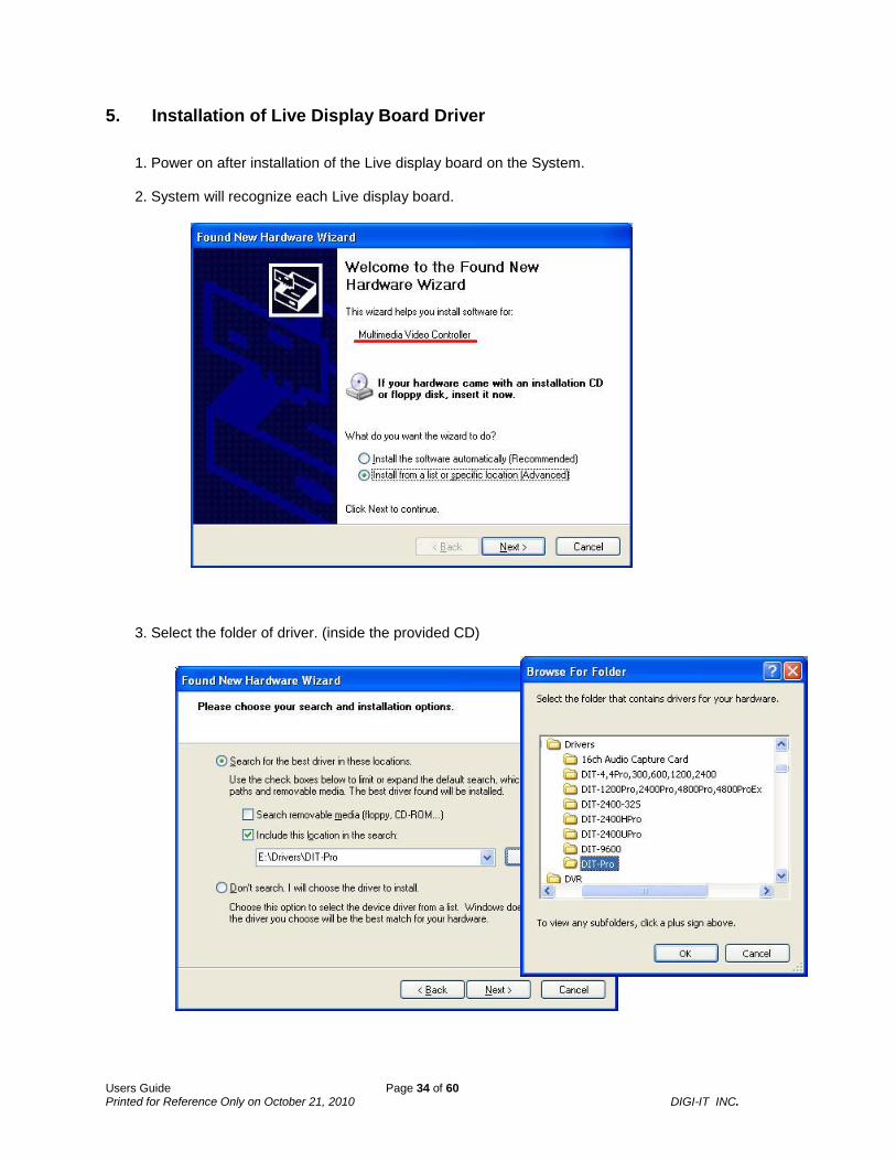
5. Installation of Live Display Board Driver
1. Power on after installation of the Live display board on the System. 2. System will recognize each Live display board.
3. Select the folder of driver. (inside the provided CD)

Users Guide Page 35 of 60 Printed for Reference Only on October 21, 2010 DIGI-IT INC.
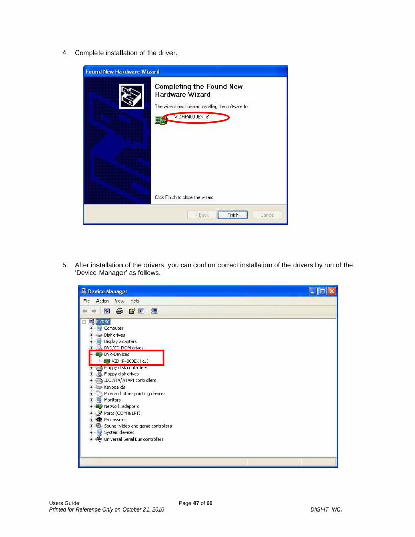
4. Complete installation of the driver.
5. After installation of the driver for 'DITLIVE Video Capture’, system will recognize ‘Audio’.

Users Guide Page 36 of 60 Printed for Reference Only on October 21, 2010 DIGI-IT INC.
6. Select the folder of driver. (inside the provided CD)
7. Complete installation of the driver.
Users Guide Page 37 of 60 Printed for Reference Only on October 21, 2010 DIGI-IT INC.
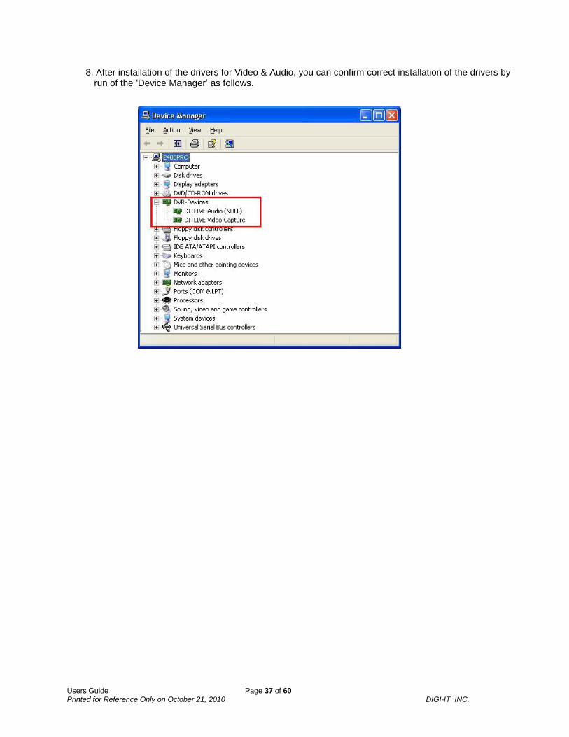
8. After installation of the drivers for Video & Audio, you can confirm correct installation of the drivers by run of the ‘Device Manager’ as follows.

Users Guide Page 38 of 60 Printed for Reference Only on October 21, 2010 DIGI-IT INC.
6. Installation of DIT-XXXXPro Board Driver ; DIT-1200Pro, DIT-2400Pro, DIT-4800Pro and DIT-4800Pro/Ex
1. Power on after installation of the board on the system.
2. System will recognize the board.
3. Select the folder of driver. (inside the provided CD)

Users Guide Page 39 of 60 Printed for Reference Only on October 21, 2010 DIGI-IT INC.
4. Complete installation of the driver.
5. After installation of the drivers for video, you can confirm correct installation of the drivers by run of
the ‘Device Manager’ as follows.

Users Guide Page 40 of 60 Printed for Reference Only on October 21, 2010 DIGI-IT INC.
7. Installation of HW Compression Board Driver
7.1. DIT-2400H.Pro
1. Power on after installation of the Live display board on the system.
2. System will recognize each the board.
3. Select the folder of driver. (inside the provided CD)

Users Guide Page 41 of 60 Printed for Reference Only on October 21, 2010 DIGI-IT INC.
4. Complete installation of the driver.
5. After installation of the driver for ‘DIT-2400HIPRO (ENC)’(2 piece), system will recognize ‘DIT-2400HIPRO (CAP)’.

Users Guide Page 42 of 60 Printed for Reference Only on October 21, 2010 DIGI-IT INC.
6. Select the folder of driver. (inside the provided CD)
7. Complete installation of the driver.

Users Guide Page 43 of 60 Printed for Reference Only on October 21, 2010 DIGI-IT INC.
8. After installation of the drivers, you can confirm correct installation of the drivers by run of the ‘Device Manager’ as follows.

Users Guide Page 44 of 60 Printed for Reference Only on October 21, 2010 DIGI-IT INC.
7.2. DIT-2400U.Pro
1. Power on after installation of the Live display board on the system.
2. System will recognize each the board.
3. Select the folder of driver. (inside the provided CD)

Users Guide Page 45 of 60 Printed for Reference Only on October 21, 2010 DIGI-IT INC.
4. Complete installation of the driver.
5. After installation of the drivers, you can confirm correct installation of the drivers by run of the
‘Device Manager’ as follows.

Users Guide Page 46 of 60 Printed for Reference Only on October 21, 2010 DIGI-IT INC.
7.3. DIT-4800U.Pro
1. Power on after installation of the Live display board on the system.
2. System will recognize each the board.
3. Select the folder of driver. (inside the provided CD)
Users Guide Page 47 of 60 Printed for Reference Only on October 21, 2010 DIGI-IT INC.
4. Complete installation of the driver.
5. After installation of the drivers, you can confirm correct installation of the drivers by run of the
‘Device Manager’ as follows.

Users Guide Page 48 of 60 Printed for Reference Only on October 21, 2010 DIGI-IT INC.
8. Installation of 16ch Audio Capture Card Driver
8.1. Installation of Video Driver
1. Power on after installation of the audio capture board on the system. 2. System will recognize each audio capture board.
3. Select a lower item, then click next.

Users Guide Page 49 of 60 Printed for Reference Only on October 21, 2010 DIGI-IT INC.
4. Select a item ’Sound, video and game controllers’, then click next.
5. Click ‘Have Disk...’.

Users Guide Page 50 of 60 Printed for Reference Only on October 21, 2010 DIGI-IT INC.
6. Select the folder of driver. (inside the provided CD)
7. Select ‘DIT A16 (V) (Multi)’, then click ‘Next’

Users Guide Page 51 of 60 Printed for Reference Only on October 21, 2010 DIGI-IT INC.
8. Click ‘Continue Anyway’.
9. Complete installation of the driver(s).

Users Guide Page 52 of 60 Printed for Reference Only on October 21, 2010 DIGI-IT INC.
8.2. Installation of Audio Driver
1. After installation of the driver(s) for video capture, system will recognize ‘Audio’.
2. Select a lower item, then click next.

Users Guide Page 53 of 60 Printed for Reference Only on October 21, 2010 DIGI-IT INC.
3. Select a item ‘Sound, video and game controllers’, then click ‘Next’.
4. Click ‘Have Disk...’.

Users Guide Page 54 of 60 Printed for Reference Only on October 21, 2010 DIGI-IT INC.
5. Select the folder of driver. (inside the provided CD)
6. Select ‘DIT A16 (V) (Multi)’, then click ‘Next’

Users Guide Page 55 of 60 Printed for Reference Only on October 21, 2010 DIGI-IT INC.
7. Click ‘Continue Anyway’.
8. Complete installation of the driver(s).

Users Guide Page 56 of 60 Printed for Reference Only on October 21, 2010 DIGI-IT INC.
9. After installation of the drivers, you can confirm correct installation of the drivers by run of the ‘Device Manager’ as follows.

Users Guide Page 57 of 60 Printed for Reference Only on October 21, 2010 DIGI-IT INC.
9. Installation of DIT-2400/32S Board Driver
1. Power on after installation of the board on the system. 2. System will recognize each the board.
3. Select the folder of driver. (inside the provided CD)

Users Guide Page 58 of 60 Printed for Reference Only on October 21, 2010 DIGI-IT INC.
4. Complete installation of the driver.
5. After installation of the drivers for video, you can confirm correct installation of the drivers by run of
the ‘Device Manager’ as follows.

Users Guide Page 59 of 60 Printed for Reference Only on October 21, 2010 DIGI-IT INC.
10. Installation of DIT-9600 Board Driver
1. Power on after installation of the board on the system. 2. System will recognize each the board.
3. Select the folder of driver. (inside the provided CD)

Users Guide Page 60 of 60 Printed for Reference Only on October 21, 2010 DIGI-IT INC.
4. Complete installation of the driver.
5. After installation of the drivers for video, you can confirm correct installation of the drivers by run of
the ‘Device Manager’ as follows.