Digging Into AutoCAD - Cadapult Software...
21
Cadapult Software Solutions, Inc. AutoCAD Civil 3D 2009 Digging Into 1 Level 1 Training Rick Ellis
Transcript of Digging Into AutoCAD - Cadapult Software...
Digging Into AutoCAD Civil 3D 2009
by
Rick Ellis Cadapult Software Solutions, Inc.
Cadapult Software Solutions, Inc.PO Box 344 • Canby Oregon 97013
www.cadapult-software.com
[email protected] • (503) 829-8929
© Cadapult Software Solutions, Inc. All rights reserved.
AutoCAD Civil 3D 2009
Digging Into
AutoCAD Civil 3D 2009
Digging Into
1
1
Level 1 TrainingRick Ellis
“Rick’s background in the civil engineering field, combined with his knowledge of the technology, uniquely qualifies him as a teacher and author of this new Civil 3D Training Guide. His thorough step-by-step manual and consistent ability with technical software led us to choose him to train Pierce County’s employees. This training guide is thoughtfully laid out with precise directions and graphics. Thank you!”
—Gael Serviss, Engineer Technician/CAD Manager Pierce County, WA
is an update to our popular book for Civil 3D 2008, taking the reader through a complete project using AutoCAD Civil 3D. It is exercise based with step-by-step procedures for many common tasks, including working with:
• Styles• GIS Data• Raster Images • Points• Surfaces• Parcels
Special explanations and tips are also included, to help users transitioning from Land Desktop.
• Alignments• Profiles • Corridors• Sections• Grading• Volumes
ISBN: 978-1-934865-02-6
9 781934 865026
9 0 0 0 0
000442 CAD COVER 8/6/08 10:11 AM Page 1
Digging Into AutoCAD Civil 3D 2009 Level 1 Training
Rick Ellis
PO Box 344 Canby Oregon 97013 www.cadapult-software.com [email protected] (503) 829-8929

Digging Into AutoCAD Civil 3D 2009
ii
Copyright © 2008 Cadapult Software Solutions, Inc. All Rights Reserved
No part of this publication may be stored in a retrieval system, transmitted, or reproduced in any way, including but not limited to photocopy, photograph, magnetic or other record, without the prior agreement and written consent of the publisher. Publisher: Cadapult Software Solutions, Inc. The author and publisher have made their best efforts to prepare this book, and the content it is based upon final release software. Cadapult Software Solutions, Inc. reserves the right to revise this book at any time. In no event shall Cadapult Software Solutions, Inc. or any of the authors or contributors be liable to anyone for special, collateral, incidental, or consequential damages in connection with or arising out of purchase or use of these materials. The liability to Cadapult Software Solutions, Inc., regardless of the form of action, shall not exceed the purchase price of the materials described herein. The dataset provided is for illustration purposes only. While it is based on real world information to add relevance to the exercises, it has been altered and modified to more effectively demonstrate certain features as well as to protect all parties involved. The data should not be used for any project work and may not represent actual places or things. The following are registered trademarks of Autodesk, Inc.: AutoCAD, AutoCAD Map, Autodesk, Autodesk Map Guide, Autodesk Map, Autodesk Map 3D, Autodesk Civil 3D, Autodesk Land Desktop, AutoCAD Map 3D, AutoCAD Civil 3D, AutoCAD Land Desktop, LDT, LDD, Autodesk Raster Design, DWF, DWF Viewer, Softdesk, Volo, Volo View, AutoLISP, AutoCAD Data Extension, AutoCAD LT, Heidi, AutoSNAP, AutoTrack, DesignCenter, DWG Linking, DXF, PolarSnap, Visual LISP, ADE, ADI. All other brand names, product names or trademarks belong to their respective holders. ISBN 978-1-934865-02-6

Digging Into AutoCAD Civil 3D 2009
iii
About the Author Rick Ellis is the founder and President of Cadapult Software Solutions, Inc., where he provides training and consulting services to clients around the country helping them get the most out of their design software investment. Rick specializes in AutoCAD Civil 3D, AutoCAD Map 3D, AutoCAD Land Desktop, and AutoCAD Raster Design. He is a member of the Autodesk Developer Network, author of several books including “Digging Into AutoCAD Civil 3D 2008”, “Digging Deeper Into Autodesk Civil 3D 2008”, “Digging Into Autodesk Land Desktop 2006” and “Digging Into Autodesk Map 3D 2009”, co-author of “Introducing Autodesk Civil 3D”, a select author for CAD Digest, and an instructor for the AUGI training program and Autodesk University. Prior to founding Cadapult Software Solutions Rick worked as a CAD Manager and Civil Designer and then as the Technical Services Manager for an Autodesk Reseller. He brings this real world experience and industry knowledge to his training and consulting projects to provide practical examples and solutions to clients. You can email Rick at: [email protected] About the Technical Editor Russell Martin is an independent consultant who has worked with spatial data and cartographic design tools since 1985, on several different platforms and in many different business and academic settings. He pioneered the position of Staff Geographer, and later served as Network Administrator and CAD Manager at a multi-disciplinary environmental engineering firm. He has assisted with the development of many computer systems involving spatial data, for industries as diverse as transportation, property management, engineering, and facilities management. He also enjoys being a cartographic designer and collects atlases, maps and globes. Russell is a member of the Association of American Geographers, the Autodesk Developer Network, and co-author of “Digging Into Autodesk Map 3D 2009”. You can email Russell at: [email protected]

Digging Into AutoCAD Civil 3D 2009
iv
About Cadapult Software Solutions, Inc. www.cadapult-software.com Founded in 2002, Cadapult Software Solutions, Inc. is an independently owned small business located near Portland, Oregon specializing in training, consulting services, and technical support for CAD systems with a focus on the Civil/Survey/GIS industry. Cadapult Software Solutions helps clients maximize the return on their software investment through training classes, consulting services, and support. We offer a wide range of Training options, from standard open enrollment classes to customized on-site training. Our mobile training lab gives us the flexibility to bring classes to our clients regardless of the location. Support options ranging from telephone support to on-site visits help to ensure the continued success of your CAD solution. Although we hold several certifications with Autodesk, Cadapult Software Solutions is an independent company and therefore can provide recommendations and solutions that best fit a clients needs rather than being limited to a specific company’s product line. Further affiliations with other consultants and software companies give Cadapult Software Solutions a broad range of experience and industry knowledge to draw from that is not common for a company of its size. Acknowledgements Rick Ellis I would like to thank all the people who made this book possible. There is no way that I can adequately explain the importance of their involvement. But I can simply state that this project could not have been completed without any of them. Many thanks to Russell Martin for his work as Technical Editor on this project. His input, suggestions, and collaboration on this book were invaluable. Thank you to Brandt Melick and the City of Springfield, Oregon for providing the project data. And most of all, thank you to my wife Katie, and our children Courteney, Lucas, and Thomas for their love and support. This project would never have been possible without your encouragement and understanding.

Digging Into AutoCAD Civil 3D 2009
v
Table of Contents
Chapter 1 Introduction .......................................................1 1.1 Overview.................................................................... 2 1.2 Project Overview.......................................................... 2 1.3 Style Conventions ......................................................... 3 1.4 Included Data .............................................................. 4 1.5 Description of AutoCAD Civil 3D ........................................ 5
1.5.1 Program Interface ............................................. 5 1.5.2 Drawing Window Colors....................................... 7 1.5.3 Workspaces ..................................................... 9 1.5.4 Dynamic Input.................................................. 9 1.5.5 Data Management ............................................10 1.5.6 Styles ...........................................................10
Chapter 2 Data Collection and Base Map Preparation................ 11 2.1 Overview...................................................................12
2.1.1 Concepts .......................................................12 2.1.2 Terms...........................................................13
2.2 Importing GIS Data .......................................................14 2.2.1 Importing ESRI Shapefiles ...................................14 2.2.2 Controlling the Display of Polygons........................24 2.2.3 Viewing GIS Attributes in AutoCAD ........................25
2.3 Using Queries to Manage and Share Data.............................26 2.3.1 Attaching Source Drawings..................................26 2.3.2 Defining a Query..............................................33 2.3.3 Saving Changes Back To the Source Drawings............38
2.4 Inserting Images and the Project Boundary ..........................42 2.4.1 Inserting a Registered Image ...............................42 2.4.2 Adding the Project Area.....................................46
2.5 Importing Point and Breakline Information from Aerial Mapping.48 2.5.1 Attaching Source Drawings..................................48 2.5.2 Defining a Compound Query ................................52
2.6 Chapter Summary ........................................................62
Chapter 3 Preliminary Layout............................................. 63 3.1 Overview...................................................................64
3.1.1 Concepts .......................................................64 3.1.2 Styles ...........................................................65
3.2 Creating a Preliminary Existing Ground Surface.....................66 3.2.1 Creating a Surface............................................66 3.2.2 Adding Surface Data .........................................70 3.2.3 Changing the Surface Style to Control Display...........74 3.2.4 Using the Object Viewer ....................................75

Digging Into AutoCAD Civil 3D 2009
vi
3.3 Creating a Preliminary Alignment .....................................77 3.3.1 Drafting the Preliminary Alignment .......................77
3.4 Creating Points from an Alignment....................................83 3.4.1 Establishing the Point Settings .............................83 3.4.2 Setting Points on the Alignment ...........................86
3.5 Creating a Point Group and Exporting the Points ...................88 3.5.1 Creating a Point Group ......................................89 3.5.2 Creating a Point Import/Export Format ..................91 3.5.3 Exporting Points to an ASCII File ...........................94
3.6 Chapter Summary ........................................................95
Chapter 4 Creating a Survey Plan ........................................ 97 4.1 Overview...................................................................98
4.1.1 Concepts .......................................................98 4.1.2 Styles ...........................................................99
4.2 Importing Survey Points ............................................... 100 4.2.1 Creating a Description Key File .......................... 100 4.2.2 Importing Points from an ASCII File ..................... 107 4.2.3 Confirming the Description Keys Worked Properly.... 110
4.3 Working with Point Groups ........................................... 111 4.3.1 Locking Points and Group Properties.................... 111 4.3.2 Creating a Point Group for Property Corners .......... 112 4.3.3 Creating a Point Group for Center Line Points ........ 114 4.3.4 Creating a Point Group for Breakline Points ........... 115 4.3.5 Creating a Point Group for Tree Points ................. 116
4.4 Controlling Point Display.............................................. 117 4.4.1 Creating Point Styles....................................... 117 4.4.2 Creating Point Label Styles ............................... 122 4.4.3 Controlling Point Display with Point Groups ........... 134 4.4.4 Controlling the Dragged State............................ 136 4.4.5 Controlling Point Label Size in Model Space ........... 138 4.4.6 Controlling Point Group Display Order .................. 139
4.5 Drawing Linework Using Transparent Commands ................. 141 4.5.1 Drawing Lines by Point Number .......................... 141 4.5.2 Drawing Lines by a Range of Point Numbers ........... 142 4.5.3 Drawing Lines by Point Object ........................... 144
4.6 Working with Parcels .................................................. 146 4.6.1 Defining a Parcel from Existing Geometry.............. 146 4.6.2 Creating a Parcel Area Report............................ 150 4.6.3 Creating a Parcel Legal Description Report ............ 152
4.7 Labeling Linework...................................................... 155 4.7.1 Labeling Parcel Lines ...................................... 155 4.7.2 Working with Parcel Segment Labels.................... 158 4.7.3 Creating a Line Tag Style ................................. 159 4.7.4 Tagging Parcel Lines ....................................... 162

Digging Into AutoCAD Civil 3D 2009
vii
4.7.5 Creating a Line Table ...................................... 163 4.7.6 Creating a Parcel Area Table ............................. 166 4.7.7 Labeling AutoCAD Objects ................................ 176
4.8 Additional Exercises ................................................... 182 4.9 Chapter Summary ...................................................... 182
Chapter 5 Building a Survey Quality Surface..........................183 5.1 Overview................................................................. 184
5.1.1 Concepts ..................................................... 184 5.1.2 Styles ......................................................... 184
5.2 Building a Surface from Survey Data ................................ 185 5.2.1 Creating a Point Group to Be Used As Surface Data .. 185 5.2.2 Creating the Survey Surface .............................. 186 5.2.3 Adding Point Group Data to a Surface .................. 189 5.2.4 Creating Breaklines by Point Number ................... 190 5.2.5 Creating Breaklines by Point Selection.................. 191 5.2.6 Adding Breaklines to the Surface ........................ 193 5.2.7 Viewing the Surface........................................ 195
5.3 Editing the Surface..................................................... 196 5.3.1 Editing Point Data .......................................... 196 5.3.2 Editing Breaklines .......................................... 198 5.3.3 Deleting Lines ............................................... 199 5.3.4 Pasting Surfaces ............................................ 201
5.4 Surface Analysis ........................................................ 204 5.4.1 Displaying Slope Arrows ................................... 204 5.4.2 Elevation Banding .......................................... 205 5.4.3 Slope Analysis ............................................... 211
5.5 Working with Contours ................................................ 216 5.5.1 Displaying a Surface as Contours......................... 216 5.5.2 Controlling Contour Display............................... 218 5.5.3 Labeling Contours .......................................... 223 5.5.4 Moving Contour Labels..................................... 223 5.5.5 Deleting Contour Labels ................................... 224 5.5.6 Labeling Only the Major Contours ....................... 224 5.5.7 Editing Contour Labels..................................... 226 5.5.8 Controlling the Display of Contour Label Lines ........ 230 5.5.9 Controlling Surface Display for Performance .......... 232
5.6 Chapter Summary ...................................................... 233
Chapter 6 Working with Proposed Horizontal Alignments..........235 6.1 Overview................................................................. 236
6.1.1 Concepts ..................................................... 236 6.1.2 Styles ......................................................... 237
6.2 Laying Out the Horizontal Alignment ............................... 238 6.2.1 Default Curve Settings ..................................... 238

Digging Into AutoCAD Civil 3D 2009
viii
6.2.2 Creating Tangents with Curves........................... 242 6.3 Editing Alignments ..................................................... 243
6.3.1 Editing Alignments Graphically........................... 243 6.3.2 Editing Alignments in Grid View ......................... 243
6.4 Stationing and Offsets ................................................. 245 6.4.1 Working with Alignment Labels .......................... 245 6.4.2 Changing the Stationing of an Alignment............... 246 6.4.3 Labeling Station and Offset Values ...................... 248 6.4.4 Creating Alignment Offsets ............................... 249
6.5 Laying Out Parcels ..................................................... 249 6.5.1 Creating Right of Way Parcels ............................ 249 6.5.2 Merging Parcels ............................................. 251 6.5.3 Creating Parcels Manually................................. 252 6.5.4 Creating Parcels with the Slide Bearing Tool .......... 255 6.5.5 Creating Parcels Automatically .......................... 257 6.5.6 Editing Parcels .............................................. 260 6.5.7 Deleting Parcels ............................................ 260 6.5.8 Renumbering Parcels ...................................... 261
6.6 Working With Parcel Styles and Labels ............................. 263 6.6.1 Controlling Parcel Display................................. 263 6.6.2 Creating Parcel Styles ..................................... 264 6.6.3 Creating Parcel Area Label Styles ....................... 269 6.6.4 Changing the Styles of Multiple Parcels................. 275
6.7 Additional Exercises ................................................... 277 6.8 Chapter Summary ...................................................... 277
Chapter 7 Working with Profiles.........................................279 7.1 Overview................................................................. 280
7.1.1 Concepts ..................................................... 280 7.1.2 Styles ......................................................... 280
7.2 Creating an Existing Ground Profile ................................. 281 7.2.1 Sampling and Drawing the Profile ....................... 281 7.2.2 Changing the Profile View Style.......................... 289 7.2.3 Creating a Profile View Style ............................. 290 7.2.4 Creating Additional Profile Views........................ 298
7.3 Creating Profiles of Finished Ground................................ 300 7.3.1 Constructing the Finished Ground Centerline.......... 300 7.3.2 Editing the Profile Graphically ........................... 305 7.3.3 Editing the Profile in Grid View .......................... 306 7.3.4 Working with Profile Labels............................... 307 7.3.5 Adding Profile Labels ...................................... 310 7.3.6 Working with Profile View Bands ........................ 311 7.3.7 Adding Profile View Bands ................................ 313
7.4 Chapter Summary ...................................................... 314

Digging Into AutoCAD Civil 3D 2009
ix
Chapter 8 Corridor Modeling .............................................315 8.1 Overview................................................................. 316
8.1.1 Concepts ..................................................... 316 8.1.2 Styles ......................................................... 316
8.2 Working with Assemblies.............................................. 317 8.2.1 Subassembly Catalogs...................................... 317 8.2.2 Creating an Assembly ...................................... 319
8.3 Working with Corridors ................................................ 326 8.3.1 Creating a Corridor......................................... 326 8.3.2 Editing a Corridor........................................... 332 8.3.3 Creating Corridor Surfaces ................................ 333 8.3.4 Viewing and Editing Corridor Sections .................. 337 8.3.5 Exporting Corridor Points ................................. 339
8.4 Working with Sections ................................................. 345 8.4.1 Creating Sample Lines ..................................... 345 8.4.2 Creating a Section Group Plot Style ..................... 349 8.4.3 Creating Section Views .................................... 352 8.4.4 Volume Calculations ....................................... 357 8.4.5 Creating a Mass Haul Diagram ............................ 361 8.4.6 Editing a Corridor to Update Volumes................... 364
8.5 Creating a Surface Showing Final Site Conditions................. 365 8.5.1 Pasting Surfaces ............................................ 365
8.6 Additional Exercises ................................................... 368 8.7 Chapter Summary ...................................................... 368
Chapter 9 Grading ..........................................................369 9.1 Overview................................................................. 370
9.1.1 Concepts ..................................................... 370 9.1.2 Styles ......................................................... 370
9.2 Working with Grading Groups ........................................ 371 9.2.1 Creating a Grading Group ................................. 371 9.2.2 Creating a Grading Object ................................ 374 9.2.3 Creating a Grading Infill ................................... 381 9.2.4 Reviewing Grading Group Properties .................... 383
9.3 Volume Calculations ................................................... 385 9.3.1 Creating a Grid Volume Surface.......................... 385 9.3.2 Creating a TIN Volume Surface........................... 389 9.3.3 Displaying Cut and Fill with Surface Styles............. 392 9.3.4 Creating a Legend for Cut and Fill Depths.............. 394
9.4 Chapter Summary ...................................................... 395

Sample Exercise
Digging Into AutoCAD Civil 3D 2009
66 | Chapter 3
3.2 Creating a Preliminary Existing Ground Surface
In this set of exercises, you will create a preliminary surface of the existing ground from the AutoCAD objects that you queried into the drawing in the previous chapter. In later chapters, you will build a surface from survey data and merge it with the preliminary surface, using the preliminary surface to add buffer data around your survey.
3.2.1 Creating a Surface
A Surface in Civil 3D is an Object. This surface object contains the surface definition and is saved in the drawing on a layer just like any other AutoCAD object. The surface object can be displayed many different ways by changing the surface style. As an example the surface can be displayed as triangles, contours, or elevation bands.
1. Continue working in the drawing Design.dwg.
2. If it is open, Close the Map Task Pane.
3. If the Toolspace is not visible, turn it on by selecting General ⇒ Toolspace.
4. On the Prospector tab of the Toolspace, right-click on Surfaces and select ⇒ Create Surface.

Digging Into AutoCAD Civil 3D 2009
Preliminary Layout | 67
5. Confirm that TIN surface is selected as Type.
The TIN Surface type is the most common type of surface. It can be created from many different types of data that form a triangulated irregular network.
You can also create Grid Surfaces that are optimized for data on a regularly spaced grid. A common use of the Grid Surface is for building a surface from DEM data.
TIN Volume and Grid Volume surfaces can also be created for volume calculations between two surfaces. These are similar to the Composite Volume and Grid Volume calculations in Land Desktop.
6. Click the Surface Layer button to open the Object Layer dialog box.

Digging Into AutoCAD Civil 3D 2009
68 | Chapter 3
7. Set the Modifier to Suffix.
8. Enter "-*" as the Modifier value.
This will add the surface name as a suffix to the surface layer.
9. Click <<OK>> to close the Object Layer dialog box.

Digging Into AutoCAD Civil 3D 2009
Preliminary Layout | 69
10. Enter "Pre-EG" for the Surface Name.
11. Click in the Style Value field to activate the Ellipses <<…>> button, and then click it to select a Style.
12. Select the Style Border & Triangles & Points from the drop-down list.
This will set your surface to display a standard looking TIN as soon as surface data is added.

Digging Into AutoCAD Civil 3D 2009
70 | Chapter 3
13. Click <<OK>> to close the Select Surface Style dialog box.
14. Click <<OK>> to close the Create Surface dialog box.
The surface is now created and can be found in the Prospector. At this point the surface does not have any data so it is not displayed in the drawing editor.
3.2.2 Adding Surface Data
Once a surface is created you can add many different types of data to construct the model. The first step in this process is to find out what type of data you have available. You may want to List the properties of objects that you intend to use in the surface to find out what type of an object they are and if they have an elevation assigned to them. For example it is important to know if your spot elevations are AutoCAD points, blocks, or text. If they have elevations you can use any of these but you need to know what they are so that you can use the appropriate command.
1. Turn off the layers EX-BREAKLINE and Project Boundary to isolate the spot elevations layer.
2. On the Prospector tab of the Toolspace, expand the Surfaces node.
3. Expand the Surface Pre-EG.
4. Expand the Definition node under Pre-EG.
5. Right-click on Drawing Objects under the Definition node and select ⇒ Add.
Digging Into AutoCAD Civil 3D 2009
Preliminary Layout | 71
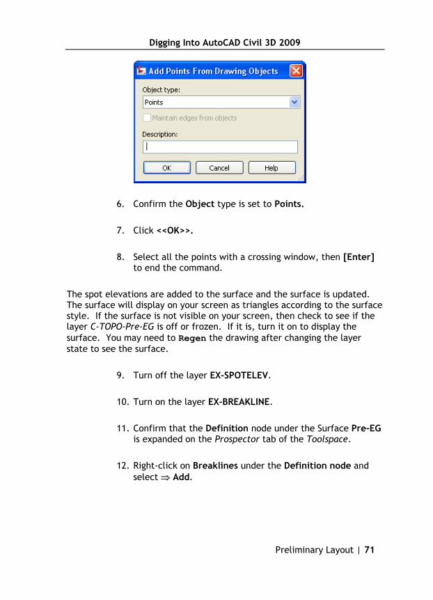
6. Confirm the Object type is set to Points.
7. Click <<OK>>.
8. Select all the points with a crossing window, then [Enter] to end the command.
The spot elevations are added to the surface and the surface is updated. The surface will display on your screen as triangles according to the surface style. If the surface is not visible on your screen, then check to see if the layer C-TOPO-Pre-EG is off or frozen. If it is, turn it on to display the surface. You may need to Regen the drawing after changing the layer state to see the surface.
9. Turn off the layer EX-SPOTELEV.
10. Turn on the layer EX-BREAKLINE.
11. Confirm that the Definition node under the Surface Pre-EG is expanded on the Prospector tab of the Toolspace.
12. Right-click on Breaklines under the Definition node and select ⇒ Add.

Digging Into AutoCAD Civil 3D 2009
72 | Chapter 3
13. Enter "Aerial Survey" for the Description.
14. Confirm that the Type is set to Standard.
You will not use any Weeding or Supplementing factors in this exercise. These options allow you to remove or add vertices to breaklines respectively. These are useful options if you have breaklines that have been over digitized and may have thousands of extra vertices very close together or if you need to add vertices to a breakline that has long distances between vertices.
15. Click <<OK>>.
16. Pick the breaklines with a crossing window.
The breaklines are added to the surface and the surface is updated.

Digging Into AutoCAD Civil 3D 2009
Preliminary Layout | 73
17. Turn on the layer Project Boundary.
18. Confirm that the Definition node under the Surface Pre-EG is expanded on the Prospector tab of the Toolspace.
19. Right-click on Boundaries under the Definition node and select ⇒ Add.
20. Enter "Project Limits" for the Name.
21. Confirm that the Type is set to Outer.
22. Confirm that the option for Non-destructive breaklines is Disabled.
Enabling the Non-destructive breaklines option trims the surface at the boundary while disabling it erases any surface lines that cross the boundary. This option is useful when you have good surface data on both sides of the boundary and are using the boundary to limit the extents of the surface. It is typically not used for outer boundaries.
23. Click <<OK>>.
24. Pick the Boundary.

Digging Into AutoCAD Civil 3D 2009
74 | Chapter 3
The boundary is added to the surface and the surface is updated. The surface is dynamically linked to all of its surface data. So if you edit a point, breakline, or boundary the surface and the corresponding node under the surface definition will display as "Out of date" in the Prospector. If you right-click on the surface name in the Prospector and select Rebuild the surface will be updated to reflect the changes in the surface data. The undo command can be used to undo any changes to the surface or the surface data.
25. Save the drawing.
3.2.3 Changing the Surface Style to Control Display
The surface style controls the display of the surface. By changing the surface style you can display the surface in many different ways. Creating and editing surface styles will be covered in detail in Chapter 5. For now you should just get comfortable with the concept that surfaces can be displayed many different ways and that the display is controlled by the surface style.
1. Turn off the layers EX-BREAKLINE and Project Boundary.
You should now see the surface, displayed as triangles, by itself without the breaklines or boundary.
2. On the Prospector tab of the Toolspace, right-click on Surface Pre-EG and select ⇒ Surface Properties.

Digging Into AutoCAD Civil 3D 2009
by
Rick Ellis Cadapult Software Solutions, Inc.
Cadapult Software Solutions, Inc.PO Box 344 • Canby Oregon 97013
www.cadapult-software.com
[email protected] • (503) 829-8929
© Cadapult Software Solutions, Inc. All rights reserved.
AutoCAD Civil 3D 2009
Digging Into
AutoCAD Civil 3D 2009
Digging Into
1
1
Level 1 TrainingRick Ellis
“Rick’s background in the civil engineering field, combined with his knowledge of the technology, uniquely qualifies him as a teacher and author of this new Civil 3D Training Guide. His thorough step-by-step manual and consistent ability with technical software led us to choose him to train Pierce County’s employees. This training guide is thoughtfully laid out with precise directions and graphics. Thank you!”
—Gael Serviss, Engineer Technician/CAD Manager Pierce County, WA
is an update to our popular book for Civil 3D 2008, taking the reader through a complete project using AutoCAD Civil 3D. It is exercise based with step-by-step procedures for many common tasks, including working with:
• Styles• GIS Data• Raster Images • Points• Surfaces• Parcels
Special explanations and tips are also included, to help users transitioning from Land Desktop.
• Alignments• Profiles • Corridors• Sections• Grading• Volumes
ISBN: 978-1-934865-02-6
9 781934 865026
9 0 0 0 0
000442 CAD COVER 8/6/08 10:11 AM Page 1