Diffuse Ys. Directional Brightness Measurement S-5 Brightmeter... · Technical Bulletin No. 101...
6
Technical Bulletin No. 101 Diffuse Ys. Directional Brightness Measurement By S. J. Popson President, Technidyne Corporation, New Albany, In. U.S.A. Abstract A description of the optical geometries of- the two types of brightness testers most commonly used in the Pulp & Paper Industry is presented. An historical discussion of the development and accep- tance of the two types of brightness testers, one employing directional geometry and the other em- ploying diffuse geometry, is also presented pointing out the reasons for adoption of diffuse geom- etry for brightness measurement by the European and Canadian Pulp and Paper Industries and adoption of directional geometry by the American Pulp and Paper Industry. The technical and practical advantages and disadvantages of each geometry are discussed as well as their relationship to end product useage. Experimental data on several grades of paper and clay confirm the disagree- ment between the two standard brightness scales due to differences in illuminating and viewing geometries. The data also substantiates the capability of instruments employing diffuse geometry to average point to point variations encountered in pulp and to minimize directionality effects encountered in embossed pulps or machine made papers. Difficulties encountered in attempting to utilize diffuse brightness testers for the measurement of fluorescent papers are discussed and documented. INTRODUCTION A debate has raged for many years in the Paper In- dustry over the relative merits of measuring papet- makers' brightness utilizing instruments employing either directional or diffuse geometry. This argument stems from the fact that brightness values are depen- dent upon the geometry of the testing instrument used to make the measurements. It is commonly recognized that brightness measurements made by two testers with different geometries will not agree (1). The geometry of an optical instrument refers to the physical relationship of the optical components which make up the instrument such as lamps, lenses, reflec- tors, apertures, etc. The two geometries most commonly used in brightness testers in the pulp and paper industry are shown in Figure 1. The directional geometry re- ferred to as 45°-0° is so called because the lamp and lens system produce a beam of light which directly strikes the sample at an angle of 45° with the perpen- dicular. The receiving lens system and photocell collect only the reflected light which is contained about an axis which is perpendicular to the sample (0°). This 45°-0° directional geometry is specified in TAPPI Standard T452 which further defines each geometric parameter such as size of illuminated area, viewed are:a, cone angle, etc. The diffuse geometry shown in Figure 1 is referred to as diffuse-Oo which means that the illumination from the lamps strikes the inner wall of a sphere, which is coated with a high reflectance white material, and mul- tiple reflections from this surface diffuse the light be- fore it strikes the sample. The reflected light is viewed by a photocell positioned to view the sample perpen- dicularly (0°). This diffuse illumination-direct viewing (0°) geometry has been specified in ISO Standards T2469 and 2470 as well as Canadian, Scandinavian and other brightness standards. The size of the sphere, area of illumination and view, and the area of openings in the sphere are geometric variables which also affect the measurement, and therefore, must be specified. FIG.1 EXAMPLES OF DIRECTIONAL AND DIFFUSE GEOMETRIES COMMONLY EMPWYED IN PULP AND PAPER BRIGHTNESS TESTERS SAMPLE I NTEGRATI NG SPHERE GLOSS TRAP ~ \ ! :. ,w..~ j)'''.' PHOTOCelL SAMPLE DIRECTIONAL GEOMETRY (..'ILLUMINATION-O'VIEWING) DIFFUSE. GEOMETRY (OIFFUSE ILLUMINATION -O'VIEWING) HISTORICAL DEVELOPMENT Directional Brightness Measurement The first paper brightness tester utilizing directional geometry as shown in Fig. 1, the GE Reflection Meter, was developed and introduced to the Pulp and Paper Industry in the early 1930's. Because of the difficulty of producing instruments which agreed with each other
Transcript of Diffuse Ys. Directional Brightness Measurement S-5 Brightmeter... · Technical Bulletin No. 101...

Technical Bulletin No. 101
Diffuse Ys. Directional Brightness Measurement
By S. J. PopsonPresident, Technidyne Corporation, New Albany, In. U.S.A.
Abstract
A description of the optical geometries of- the two types of brightness testers most commonly usedin the Pulp & Paper Industry is presented. An historical discussion of the development and accep-tance of the two types of brightness testers, one employing directional geometry and the other em-ploying diffuse geometry, is also presented pointing out the reasons for adoption of diffuse geom-etry for brightness measurement by the European and Canadian Pulp and Paper Industries andadoption of directional geometry by the American Pulp and Paper Industry. The technical andpractical advantages and disadvantages of each geometry are discussed as well as their relationshipto end product useage. Experimental data on several grades of paper and clay confirm the disagree-ment between the two standard brightness scales due to differences in illuminating and viewinggeometries. The data also substantiates the capability of instruments employing diffuse geometryto average point to point variations encountered in pulp and to minimize directionality effectsencountered in embossed pulps or machine made papers. Difficulties encountered in attempting toutilize diffuse brightness testers for the measurement of fluorescent papers are discussed anddocumented.
INTRODUCTION
A debate has raged for many years in the Paper In-dustry over the relative merits of measuring papet-makers' brightness utilizing instruments employingeither directional or diffuse geometry. This argumentstems from the fact that brightness values are depen-dent upon the geometry of the testing instrument usedto make the measurements. It is commonly recognizedthat brightness measurements made by two testers withdifferent geometries will not agree (1).
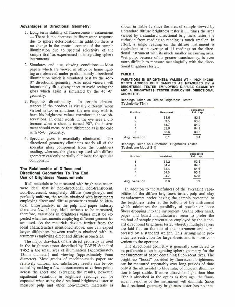
The geometry of an optical instrument refers to thephysical relationship of the optical components whichmake up the instrument such as lamps, lenses, reflec-tors, apertures, etc. The two geometries most commonlyused in brightness testers in the pulp and paper industryare shown in Figure 1. The directional geometry re-ferred to as 45°-0° is so called because the lamp andlens system produce a beam of light which directlystrikes the sample at an angle of 45° with the perpen-dicular. The receiving lens system and photocell collectonly the reflected light which is contained about an axiswhich is perpendicular to the sample (0°). This 45°-0°directional geometry is specified in TAPPI StandardT452 which further defines each geometric parametersuch as size of illuminated area, viewed are:a, coneangle, etc.
The diffuse geometry shown in Figure 1 is referredto as diffuse-Oo which means that the illumination fromthe lamps strikes the inner wall of a sphere, which iscoated with a high reflectance white material, and mul-tiple reflections from this surface diffuse the light be-
fore it strikes the sample. The reflected light is viewedby a photocell positioned to view the sample perpen-dicularly (0°). This diffuse illumination-direct viewing(0°) geometry has been specified in ISO StandardsT2469 and 2470 as well as Canadian, Scandinavianand other brightness standards. The size of the sphere,area of illumination and view, and the area of openingsin the sphere are geometric variables which also affectthe measurement, and therefore, must be specified.
FIG.1 EXAMPLES OF DIRECTIONAL AND DIFFUSE GEOMETRIES COMMONLY EMPWYEDIN PULP AND PAPER BRIGHTNESS TESTERS
SAMPLE
I NTEGRATI NGSPHERE
GLOSS TRAP
~ \ !:.
,w..~ j)'''.'PHOTOCelL
SAMPLE
DIRECTIONAL GEOMETRY(..'ILLUMINATION-O'VIEWING)
DIFFUSE. GEOMETRY(OIFFUSEILLUMINATION-O'VIEWING)
HISTORICAL DEVELOPMENT
Directional Brightness Measurement
The first paper brightness tester utilizing directionalgeometry as shown in Fig. 1, the GE Reflection Meter,was developed and introduced to the Pulp and PaperIndustry in the early 1930's. Because of the difficultyof producing instruments which agreed with each other

within the limits of visual discrimination, the Instituteof Paper Chemistry established a "Brightness Stand-ardization System" whereby all newly manufacturedbrightness testers were matched geometrically photo-metrically and spectrally to a master instrument. Inaddition, calibrated opal glass and paper standa~dswere issued on a monthly subscription basis to allowbrightness tester users to maintain close agreement withthe IPC master. TAPPI Standard T452, which wasbased on the GE Reflection Meter, was adopted byTAPPI in 1948. Subsequently, brightness testers con-forming to TAPPI T452 have been manufactured byMartin Sweets Company, Diano Corporation and Tech-nidyne Corporation.
The success experienced by the U.S. Paper Industrywith the use of the GE Brightness Meter and its suc-cessors is mainly attributable to the rigorous and dili-gent maintenance of the brightness standardization sys-tem by the Institute of Paper Chemistry. As a result,users of the system throughout the Paper Industry havedeveloped confidence in the accuracy and reliability oftheir brightness measurements.
Diffuse Brightness MeasurementThe most commonly used diffuse brightness tester,
the Zeiss Elrepho, was introduced in the 1950's by CarlZeiss Company of Oberkochen, West Germany. TheElrepho with its integrating sphere (diffuse) geometrywas adopted by the European and Canadian Paper In-dustries and the International Standards Organization(ISO) as the standard instrument for measuring bright-ness. The Elrepho remained the only instrument manu-factured in accordance with the European, Canadianand ISO standards until the recent introduction of theTechnibrite Model TB-l by Technidyne Corporationof New Albany, Indiana, U.S.A.
In contrast to the rigorously maintained directionalbrightness scale, which has remained relatively un-changed in over 45 years, the diffuse brightness scalehas seen several major changes including:
1. The basis for setting the 100% brightness pointwas changed from the reflectance of magnesiumoxide to absolute reflectance (2). This scale changecaused all brightness readings to go down i.e. apulp previously measured at 60 brightness mightnow read 58.5
2. A gloss trap was included in the integrating sphereto exclude the specular gloss component. The in-sertion of a gloss trap is an attempt to minimizethe effect of surface reflectance, leaving onlyintrinsic brightness to be measured. Unfortunately,no gloss trap can completely exclude speculargloss from all grades of pulp and paper, there-fore, the measurements are very much a functionof the size and position of the trap. Brightnessvalues may be lower by up to 2% due to theinclusion of a gloss trap (3).
3. The use of a xenon lamp has been recommendedto boost the excitation of fluorescent papers.Sphere lining deterioration causes increasing ab-
sorption of ultraviolet (UV) energy as the liningages thereby reducing the excitation of fluores-cent dyes. The intended use of the xenon lampwas to boost the UV energy to a level sufficientto excite fluorescent papers and produce an ap-propriately higher brightness value. The use ofthe xenon attachment has not gained widespreadacceptance due to long term stability concerns,difficulty in deciding when to use the attachment,and because of its high cost.
These changes have caused some frustration amongusers of the diffuse brightness method in explaining totheir customers how the brightness of a pulp or papercan change 2% from one day to the next because abrightness scale change has been adopted. A 2% in-crease in brightness is never hard to explain, but a 2%reduction in brightness is impossible to explain to acustomer.
ADVANTAGES AND DISADVANTAGES
One might reasonably ask why a part of the world(USA) would settle on the measurement of pulp andpaper brightness by one geometry and another part ofthe world' (Canada and Europe) would settle onbrightness measurement by a different geometry. Thereason for this disagreement is that there are valid ad-vantages and disadvantages for both the diffuse anddirectional geometries of brightness measurement. Thefollowing is a synopsis of the advantages and disad-vantages:
Advantages of Diffuse Geometry:
1. Averages non-uniformities - This is a very im-portant advantage in the measurement of pulpwhich varies greatly in its uniformity. Far fewermeasurements need to be made on an instrumentwhich diffusely illuminates the sample than on adirectional reflectance instrument in order to ob-tain a representative average of the overall samplereflectance.
2. Averages ditectionality effects-Since the diffusebrightness tester illuminates the sample from everydirection, there is no change in reading associatedwith sample reorientation.
3. Simulates viewing condition - Some argue thatthe diffuse brightness tester better simulates typi-cal viewing conditions than the directional bright-ness tester. This argument pertains primarily tothe fact that the area of view in the standarddiffuse brightness tester is larger than the area ofview in the standard directional brightness tester.
4. Excludes or includes specular gloss - A glosstrap can be either included or excluded to simulatethe end product viewing conditions.
5. Minimizes translucency effect - This point alsopertains to the fact that the area of illuminationand view is larger in the- standard diffuse bright-ness tester than in the standard directional bright-ness tester.
Advantages of Directional Geometry:
1. Long term stability of fluorescence measurement- There is no decrease in fluorescent responsedue to sphere deterioration. In addition there isno change in the spectral content of the sampleillumination due to spectral selectivity, of thesample itself as experienced in integrating sphereinstruments.
2. Simulates end use viewing conditions - Mostpapers which are viewed in office or home light-ing are observed under predominantly directionalillumination which is simulated best by the 45°-0° directional geometry. Also most viewers willintentionally tilt a glossy sheet to avoid seeing thegloss which again is simulated by the 45°-0°geometry.
3. Pinpoints directionality - In certain circum-stances if the product is visually different whenviewed in two orientations; the user may wish tohave his brightness values corroborate those ob-servations. In other words, if the eye sees a dif-ference when a sheet is turned 90°, the instru-ment should measure that difference as is the casewith 45-0° geometry.
4. Specular gloss is essentially eliminated - Thedirectional geometry eliminates nearly all of thespecular gloss component from the brightnessreading, whereas, the gloss trap used with diffusegeometry can only partially eliminate the specularcomponent.
The Relationship of Diffuse andDirectional Geometries To The EndUse of Brightness Measurements
If all materials to be measured with brightness testerswere ideal, that is: non-directional, non-translucent,non-fluorescent, completely diffuse (non-glossy), andperfectly uniform, the results obtained with instrumentsemploying direct and diffuse geometries would be iden-tical. Unfortunately, in the pulp and paper industrythere are few, if any, ideal surfaces to be measured,therefore, variations in brightness values must be ex-pected when instruments employing different geometriesare used. As the materials deviate further from theideal characteristics mentioned above, one can expectlarger differences between readings obtained with in-struments employing direct and diffuse geometries.
The major drawback of the direct geometry as usedin the brightness tester described by TAPPI StandardT452 is the small area of illumination (approximately13mm diameter) and viewing (approximately 9mmdiameter). Most grades of machine-made paper arerelatively uniform and satisfactory results can be ob-tained by making a few measurements at various pointsacross the sheet and averaging the results, however,significant variations in brightness readings can beexpected when using the directional brightness tester tomeasure pulp and other non-uniform materials as
shown in Table 1. Since the area of sample viewed bya standard diffuse brightness tester is 11 times the areaviewed by a standard directional brightness tester, thevariation from reading to reading is much smaller. Ineffect, a single reading on the diffuse instrument isequivalent to an average of 11 readings on the direc-tional instrument with its much smaller measuring area.Wet pulp, because of its greater translucency, is evenmore difficult to measure meaningfully with the direc-tional brightness tester.
TABLE 1.
VARIATIONS IN BRIGHTNESS VALUES AT 1 INCH INCRE-MENTS ACROSS PULP SAMPLES AS MEASURED BY ABRIGHTNESS TESTER EMPLOYING D.\FFUSE GEOMETRYAND A BRIGHTNESS TESTER EMPLOYING DIRECTIONALGEOMETRY.
Readings Taken on Diffuse Brightness Tester(Technibrite TB-1)
Readings Taken on Directional Brightness Tester(Technidyne Model 8-4)
In addition to the usefulness of the averaging capa-bilities of the diffuse brightness tester, pulp and claymanufacturers prefer. having the sample presented tothe brightness tester at the bottom of the instrumentwhich minimizes the possibility of powder or loosefibers dropping into the instrument. On the other hand,paper and board manufacturers seem to prefer themethod of sample presentation employed by the stand-ard directional brightness tester whereby multiple layersare laid flat on the top of the instrument and com-pressed by a standard weight. This arrangement pro-vides less restriction for large sheets and is more con-venient to the operator.
The directional geometry is generally considered tobe preferable to an integrating sphere geometry for themeasurement of paper containing fluorescent dyes. Thebrightness "boost" provided by fluorescent brightenerscan be measured repeatably over .long periods of timeonly if the ultraviolet to blue ratio of incident illumina-tion is kept stable. If more ultraviolet light than bluelight is absorbed in the optics as they age, the fluor-escent response of the instrument will diminish. Sincethe directional geometry brightness tester has no inte,..
CorrugatedPosition Handsheet Pulp Lap.
1 83.6 82.82 83.5 83.63 83.7 84.04 83.6 84.15 83.6 83.6- -
Avg. variation 0.1 0.4
CorrugatedPosition Handsheet Pulp Lap
1 84.2 82.82 84.4 84.03 83.4 84.64 84.0 83.55 84.7 82.8- -
Avg. variation 0.6 0.9
grating sphere, there is much less chance of UV lightbeing absorbed, therefore, the directional instrumentshould provide excellent long term fluorescent responsestability:
Integrating sphere instruments are also subject tochanges in their response to fluorescence; a) when agloss trap is included in the integrating sphere the sam-ple opening becomes a larger percentage of the remain-ing reflective area of the sphere, causing a relativelyhigher degree of fluorescence excitation (see Tables~3,4 and 5), and b) when a fluorescent paper is measuredwith an integrating sphere instrument, the light emittedby fluorescence is reflected by the sphere wall andreilluminates the sample adding to the original illumi-nation. This effectively changes the spectral characterof the light source each time a sample is measured (4).
It should be considered that effects a) and b) de-scribed above can be taking place in combination withcontinuous changes in UV /blue ratio making the meas-urement of fluorescent materials on an integratingsphere instrument a risky proposition at best.
DISCUSSION OF EXPERIMENTAL RESULTS
The data shown in Table 1 point up the differencebetween brightness testers employing diffuse geometryand brightness testers employing directional geometrywith regard to their ability to average non-uniformitiesacross a sheet. Five readings were taken on a typicalpulp handsheet utilizing the Technibrite Model TB-1Brightness Tester which employs diffuse illumination-0°viewing geometry. Each reading was spaced one inchaway from the previous reading. Note that the maxi-mum variation from one position to the next is 0.2brightness units with an average variation from onepoint to the next of 0.1. This same test was run utiliz-ing a brightness tester employing 45° - 0° directionalgeometry (the Technidyne Model S-4 Brightness Test-er). The maximum brightness variation between twopoints spaced one inch apart on the handsheet was 1.0brightness units with an average variation betweenmeasurement points of 0.6. This data clearly indicatesthat the diffuse brightness tester, with its larger samplemeasurement area, provides better averaging of point topoint variations within the pulp. It should be noted thatthe repeatability of each instrument was carefullychecked and found to be within 0.1 brightness units toassure that the low point to point brightness variationsmeasured by the diffuse brigtness tester were actuallydue to geometric averaging rather than lack of instru-ment sensitivity.
Measurements were also made at one inch incrementson corrugated pulp lap which has considerably greatersurface variation than a handsheet. Again, the bright-ness tester employing diffuse geometry and large meas-urement area measured substantially less point to pointvariation in brightness than the tester employing direc-tional geometry.
To point up the effect of sample directionality uponbrightness measurements taken with instruments em-ploying different geometries a corrugated pulp lap,
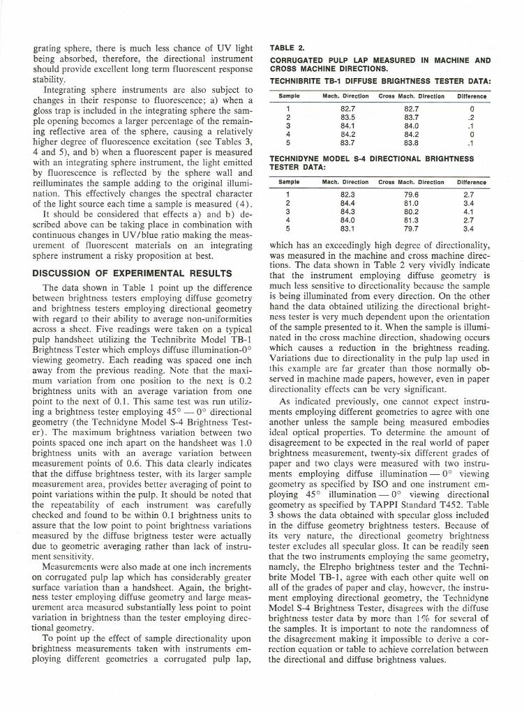
TABLE2.
CORRUGATEDPULP LAP MEASUREDIN MACHINEANDCROSS MACHINEDIRECTIONS.TECHNIBRITETB-1 DIFFUSEBRIGHTNESSTESTERDATA:
TECHNIDYN.E MODEL S-4 DIRECTIONAL BRIGHTNESSTESTER DATA:
which has an exceedingly high degree of directionality,was measured in the machine and cross machine direc-tions. The data shown in Table 2 very vividly indicatethat the instrument employing diffuse geometry ismuch less sensitive to directionality because the sampleis being illuminated from every direction. On the otherhand the data obtained utilizing the directional bright-ness tester is very much dependent upon the orientationof the sample presented to it. When the sample is illumi-nated in the cross machine direction, shadowing occurswhich causes a reduction in the brightness reading.Variations due to directionality in the pulp lap used inthis example are far greater than those normally ob-served in machine made papers, however, even in paperdirectionality effects can be very significant.
As indicated previously, one cannot expect instru-ments employing different geometries to agree with oneanother unless the sample being measured embodiesideal optical properties. To determine the amount ofdisagreement to be expected in the real world of paperbrightness measurement, twenty-six different grades ofpaper and two clays were measured with two instru-ments employing diffuse illumination - 0° viewinggeometry as specified by ISO and one instrument em-ploying 45° illumination - 0° viewing directionalgeometry as specified by TAPPI Standard T452. Table3 shows the data obtained with specular gloss includedin the diffuse geometry brightness testers. Because ofits very nature, the directional geometry brightnesstester excludes all specular gloss. It can be readily seenthat the two instruments employing the same geometry,namely, the Elrepho brightness tester and the Techni-brite Model TB-1, agree with each other quite well onall of the grades of paper and clay, however, the instru-ment employing directional geometry, the TechnidyneModel S-4 Brightness Tester, disagrees with the diffusebrightness tester data by more than 1% for several ofthe samples. It is important to note the randomness ofthe disagreement making it impossible to derive a cor-rection equation or table to achieve correlation betweenthe directional and diffuse brightness values.
Sample Mach. Direction Cross Mach. Direction Difference
1 82.7 82.7 02 83.5 83.7 .23 84.1 84.0 .14 84.2 84.2 05 83.7 83.8 .1
Sample Mach. Direction Cross Mach. Direction Difference
1 82.3 79.6 2.72 84.4 81.0 3.43 84.3 80.2 4.14 84.0 81.3 2.75 83.1 79.7 3.4

TABLE3.DATA COMPARING TWO BRIGHTNESS TESTERSEMPLOYING DIFFUSE GEOMETRY WITH ONE BRIGHTNESSTESTER EMPLOYING DIRECTIONAL GEOMETRY
SPECULAR GLOSS INCLUDED*
'Specular gloss is included in both diffuse geometry brightness testersbut the directional brightness tester always excludes specular gloss.
All three of the brightness testers used in this studywere checked and found to be in a good state of cali-bration with regard to photometry and spectral re-sponse. Each data point shown in Tables 3 and 4 is anaverage of five brightness determinations on an opticallyinfinite pad made up in accordance with the samplingprocedures described in TAPPI T400 and T452. Thegrades of paper used in this study are described in Table5. The fluorescence rankings i.e., highly fluorescent,slightly fluorescent, or non-fluorescent, were determinedby measuring the fluorescent component on a Techni-dyne Model S-4 Brightness Tester utilizing TAPPIUseful Method #548 with verification by visual obser-vation under controlled conditions. All three instrumentswere calibrated based on absolute reflectance utiliz-ing a paper transfer standard of approximately 90%brightness.
The measurements made and reported in Table 3were repeated after insertion of gloss traps in theElrepho and Technibrite TB-l Brightness Testers. Thedata thus obtained with specular gloss excluded is re-ported in Table 4 along with the data obtained on theS-4 Brightness Tester which always excludes gloss.
Again the disagreement due to geometric difference isapparent and defies any attempt at mathematical cor-relation for the wide range of brightness values andgrades utilized in this study.
CHANGE IN GEOMETRY WITHINA GIVEN INSTRUMENT
Thus far we have concerned ourselves with disagree-ment between instruments which have been designed toemploy different illuminating and viewing geometries.Now let us consider the effect of change in geometrywithin a given instrument. When a black gloss trap isinserted in the integrating sphere of a diffuse brightnesstester, the sample is no longer illuminated from everydirection as the illuminating rays surrounding a per-pendicular axis to the sample have been eliminated.This change in geometry can provide some interestingresults as shown in Table 5.
Referring to the coated grades #103, 104, and 105,which are also non-fluorescent, we can see that thedifferences between brightness readings including glossand excluding gloss are positive numbers approaching1%. This indicates that the surface reflectance from thecoated sheet (specular gloss) is contributing an addi-
TABLE 4.DATA COMPARING TWO BRIGHTNESS TESTERSEMPLOYING DIFFUSE GEOMETRY WITH ONE BRIGHTNESSTESTER EMPLOYING DIRECTIONAL GEOMETRY.
SPECULAR GLOSS EXCLUDED
DIRECTIONALDIFFUSE GEOMETRY GEOMETRY
Elrepho TB-1 S-4Brightness Comparison Comparison
101 70.92 -.60 + .34102 50.46 -.26 - .48
.... 103* 80.78 +.30 + .80zW
104* 80.46 +.20 +1.08Uen105* 81.36 +.22 +1.08W
a:0 106 57.48 -.38 - .48='
107 48.58 -.36 + .72.Ju.Z 108 81.72 +.10 - .340 109 82.30 +.26 - .76z
110 82.80 +.28 + .14111 16.24 +.02 + .84
Std. Deviation .30 .71
," j
150 73.86 +.08 - .10.Jw 151 61.66 -.34 + .02I-u 152 81.30 +.32 - .56:r:(I)(!) 153 81.18 +.16 + .80::;0(I)=' 154 77.08 -.02 + .88.Ju. 155 78.46 +.28 + .88
Std. Deviation .24 .65I
200 80.56 +.32 + .88201 77.90 +.16 - .06
Jj
202 80.74 +.36 +1.60.JU 203 81.98 +.10 - .14:r:en 204 85.42 +.02 - .02(!)w_a:
205 82.46 -.20 - .28:r:0;:).J 206 82.48 -.24 - .12u.207 84.70 0 + 1.18208 92.36 -.18 + .02
Std. Deviation .21 .73CLAY A 89.7 0 + .4
B 84.5 +.1 - .3
DIRECTIONALDIFFUSE GEOMETRY GEOMETRY
Elrepho TB-1 S-4Brightness Comparllon Comparllon
101 70.20 -.18 +1.06102 49.98 -.02 0
I- 103 79.80 +.28 +1.78zW104 79.66 +.24 1.88U
(I)105 80.56 +.14 1.88W
a:106 56.90 -.18 + .100
=' 107 47.82 +.08 1.48.Ju.108 81.44 -.14 - .06Z
0 109 81.92 -.08 - .38z110 82.84 -.02 + .10111 15.78 +.24 +1.46
Std. Deviation .16 1.26
'"j
150 73.76 +.16 0.Jw 151 61.68 -.12 0I-u 152 81.04 +.20 - .30J:(I)(!) 153 81.14 +.28 + .84::;0
154 77.14 +.04 + .82(I)='.J155 77.96 +.30 +1.38u.
Std. Deviation .28 .75200 80.80 -.14 + .64201 78.12 -.26 - .28
Jj
202 80.78 +.02 +1.56.Ju 203 82.30 -.42 - .46:r:en 204 85.82 -.46 - .42(!)w5: 205 82.86 -.42 - .68
=' 206 82.86 -.48 - .50.Ju.207 85.16 -.26 + .72208 93.10 -.46 - .72
Std. Deviation .36 .75CLAY A 89.7 0 + .4
8 84.6 -.2 - .4

tional 1% to the brightness of the sheet. Given thatpositive numbers indicate the gloss contribution of thesheet, how can one explain the negative differences ob-tained by the Elrepho on Samples 200-208? The an-swer lies in the fact that the geometry of the integratingsphere was changed when the gloss trap was inserted.Inclusion of the glosstrap reduces the effectivearea ofthe sphere waIf making the illuminated sample area alarger percentage of the total wall area. The resultingchange in illuminating conditions causes a. relativelyhigher excitation of the fluorescent papers yielding ahigher brightness value when the gloss trap is in theinstrumentthan when it is not.
SUMMARY
This investigation of advantages and disadvantagesof diffuse and directional brightness measurementgeometries leads to the conclusion that neither geometryis ideal for the measurement of all materials encoun-tered in the pulp and paper industry. Advantages ofdirectional geometry such as exclusion of specular gloss,long term fluorescent response stability and simulationof normal viewing conditions are important factors in
the measurement of paper, particularly for grades whichare coated, calendared or fluorescent. The main attri-bute of diffuse geometry, namely its ability to averagepoint to point variations, lends itself well to the meas-urement of pulp where brightness variations within agiven sample can be significant. Bearing in mind theconsiderations previously stated, it would appear thatthe choice between diffuse and directional geometryfor brightness measurement must be ultimately basedon the characteristics of the particular material to bemeasured.
TABLE6.DESCRIPTION OF SAMPLES TESTED
Sample No. DescriptionFluorescent
Component Value
101102103104105106107108109110111150151152153154155200201202203204205206207208
70# colonial white """""""'" .1267# vellum bristol , .0660# offset coated 2 sides. . . . . . . . . .. .0460# offset coated 1 side. . . . . . . . . . .. .0870# coated 1 side label paper. . . . . .. .1670# text ivory laid finish .1070# imperial ivory offset light yellow.. .0816# bond. . . . . . . . . . . . . . . . . . . . . . .. .0613# bond. . . . . . . . . . . . . . . . . . . . . . .. .0820# bond. . . . . . . . . . . . . . . . . . . . . . ., 0
unbleached kraft .049# bond. . . . . . . . . . . . . . . . . . . . . . . .1.08
20# 25% rag light gray. . . . . . . . . . .. .94110# index.. .. .. .. .. .. .. .. .. .. .." .8480# vellum bristol ,.. .5265# cover laid finish. . . . . . . . . . . . . .. .4490# index .3250# offset smooth finish. . . . . . . . . . . .2.6670# offset vellum finish . . . . . . .2.2450# offset. . . . . . . . . . . . . . . . . . . . . . . .2.6480# offset embossed finish 2.9820# ledger 3.8670# offset.. . . . . . . . . . . . . . . . . . . . . . .4.16
9# onionskin 25% rag .4.3270# pearl white offset. . . . . . . . . . . . . .4.8620# 25% rag 5.92
LITERATURE CITED
1. J. A. Van den Akker, "Standard Brightness, Color, andSpectrophotometry with Emphasis on Recent Information"Tappi Vol. 48. No. 12 (Dec., 1965).
2. Van den Akker, J. A., Dearth, L. R. and Shillcox, W. M.,"Evaluation. of Absolute Reflectance for StandardizationPurposes" J. Optical Soc. Amer., 46, 378 (1956) and 56, 250(1966).
3. W. Budde and S. Chapman, "Measurement of Brightnessand Opacity According to ISO Standards", Transactions, No.2, 61-64, 1975.
4. Margret Burns, "You Can Check Color Appearance bySpectrophotometer", Industrial Research & Development,March, 1980.
TABLE 5.
SPECULAR GLOSS COMPONENT OF BRIGHTNESS(GLOSS INCLUDED - GLOSS EXCLUDED)
Sample No. Elrepho TechnlbrlleTB.'
101 +.72 + .30102 +.48 + .20
I- coated. . . . . . . . .103 +.98 +1.00zw coated. . . . . . . . . 104 +.80 + .72U'" coated. . . . . . . . . 105 +.80 + .88wa: 106 +.58 + .380::> 107 +.76 + .32..Ju. 108 +.28 + .52Z0 109 +.38 + .72z
110 -.04 + .22111 +.62 + .24
>" j
150 +.10 + .02151 -.02 - .24152 +.26 + .38:I:'"
<!J 153 +.04 - .08::::;0 154 -.06 - .12"'::>..J 155 +.52 + .48u.
200 -.24 + .22201 -.22 + .20
Jj
202 -.04 + .30
..JU 203 -.32 + .20:I:'" 204 -.40 + .08(!)w_a: 205 -.40 - .18:I:0::> 206 -.38 - .14..Ju. 207 -.46 - .20
208 -.74 - .46


![X-one-クレイパックリーフ-単 EX INUI) EX INI]PEX INUPEX Brightness Clay Pack for your brightness life íNUP Brightness Clay Pack far your brightness life íNUP](https://static.fdocuments.net/doc/165x107/5c8b11e009d3f2d5658ce1da/x-one-ex-inui-ex-inipex-inupex-brightness-clay.jpg)
![]Ys}˝‡—dUeconweb.ucsd.edu/~v2crawford/Camerer_Ch1intro.pdf]Ys}˝‡—dU ... d(d](https://static.fdocuments.net/doc/165x107/613063f61ecc515869441112/-ysaa-v2crawfordcamererch1intropdf-ysaadu-dd.jpg)