Diffraction Methods & Electron Microscopy Lecture 3 · Diffraction lens Intermediate lens ......
75
FYS 4340/9340 course – Autumn 2016 63 Diffraction Methods & Electron Microscopy Sandeep Gorantla FYS 4340/FYS 9340 Lecture 3
Transcript of Diffraction Methods & Electron Microscopy Lecture 3 · Diffraction lens Intermediate lens ......

FYS 4340/9340 course – Autumn 2016 63
Diffraction Methods & Electron Microscopy
Sandeep Gorantla
FYS 4340/FYS 9340
Lecture 3

Lab Groups
64
THURSDAY TEM COURSE (FYS 4340/FYS 9340) LAB GROUPS PLAN
Group 1 Group 2 Group 3
9:00-11:00 12:00-14:00 14:00-16:00 Annika Utz Amalie Berg Hans Jakob Sivertsen Mollatt
Andrei Karzhou Nikita Thind Heine Ness
Martin Løvøy Hengyi zhu Henrik Riis
Martin Jensen/Anne Klemm PrasantaDhak
FYS 4340/9340 course – Autumn 2016

FYS 4340/9340 course – Autumn 2016 65
Simplified ray diagram of conventional TEM Simplified ray diagram of conventional STEM
This Lecture
66
• TEM Instrumentation – Part 2 (Text book Chapters: 5 – 9)
• TEM Specimen Preparation
(Text book Chapters: 10)
FYS 4340/9340 course – Autumn 2016

FYS 4340/9340 course – Autumn 2016 67
Electron gun
Illumination system
Imaging system
Projection and Detection system
Specimen stage
Courtesy: David Rassouw

FYS 4340/9340 course – Autumn 2016 68
FEG gun
Extraction Anode Gun lens
Monochromator
Monochromator Aperture
Accelerator
Gun Shift coils C1 aperture/mono energy slit C1 lens
C2 lens C2 aperture Condenser alignment coils
C3 lens C3 aperture Beam shift coils
Mini condenser lens Objective lens upper Specimen Stage Objective lens upper
Image Shift coils Objective aperture
Cs Corrector
SA Aperture
Diffraction lens
Intermediate lens
Projector 1 lens
Projector 2 lens HAADF detector
Viewing Chamber Phosphorous Screen BF/CCD detectors
GIF CCD detector EELS prism
Courtesy: David Rassouw, CCEM, Canada
• Electron Gun
• Electron Lens
• Apertures
• Specimen Stage/Holders • Lq. N2 Coldtrap
• Image Viewing/Recording system
• Spectrometers
• Stigmators, scan coils and beam deflecting coils
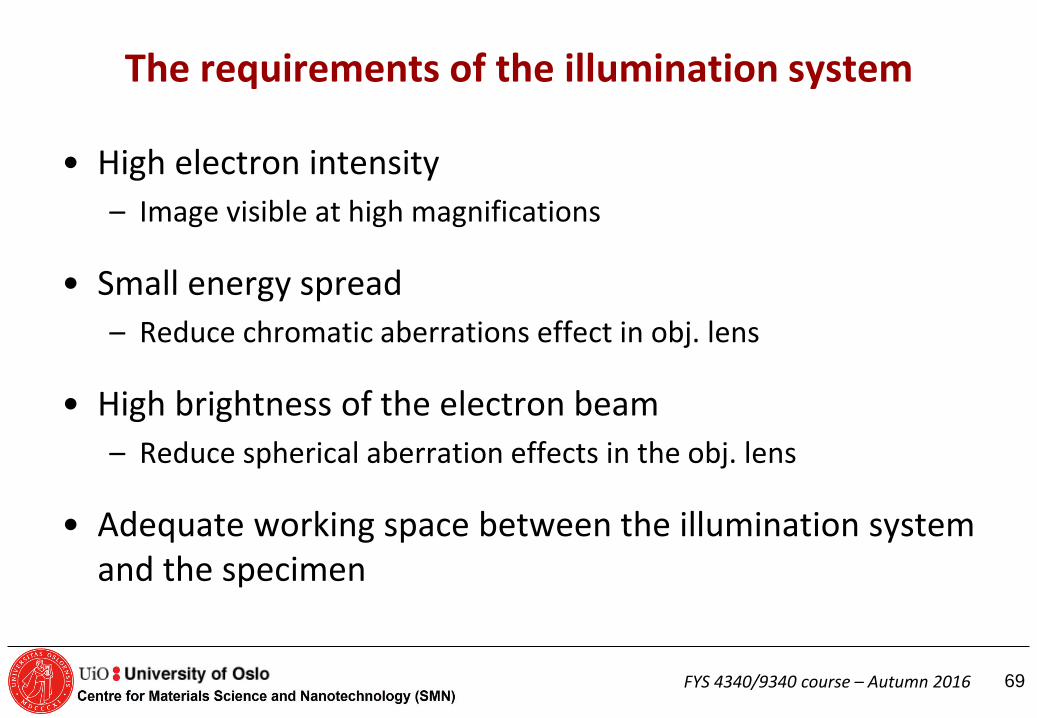
The requirements of the illumination system
• High electron intensity
– Image visible at high magnifications
• Small energy spread
– Reduce chromatic aberrations effect in obj. lens
• High brightness of the electron beam
– Reduce spherical aberration effects in the obj. lens
• Adequate working space between the illumination system and the specimen
69 FYS 4340/9340 course – Autumn 2016

The electron source
• Two types of emission sources
– Thermionic emission
• W or LaB6
– Field emission
• Cold FEG W
• Schottky FEG ZnO/W
70 FYS 4340/9340 course – Autumn 2016

The electron gun
• The performance of the gun is characterised by:
– Beam diameter, dcr
– Divergence angle, αcr
– Beam current, Icr
– Beam brightness, βcr
at the cross over
Cross over
α
d
Image of source
71 FYS 4340/9340 course – Autumn 2016

Brightness
• Brightness is the current density per unit solid angle of the source
• β = icr/(πdcrαcr)2
Beam diameter, dcr
Divergence angle, αcr
Beam current, Icr
Beam brightness, βcr at the cross over
72 FYS 4340/9340 course – Autumn 2016

The electron gun
Bias -200 V
Ground potential
-200 kV
Anode
Wehnelt cylinder
Cathode
dcr Cross over
αcr
Equipotential lines
Thermionic gun FEG
73 FYS 4340/9340 course – Autumn 2016

Thermionic guns
Filament heated to give
Thermionic emission -Directly (W) or
indirectly (LaB6)
Filament negative
potential to ground
Wehnelt produces a
small negative bias -Brings electrons to
cross over
74 FYS 4340/9340 course – Autumn 2016

Thermionic guns
75 FYS 4340/9340 course – Autumn 2016

Thermionic emission
• Current density:
– Ac: Richardson’s constant, material dependent
– T: Operating temperature (K)
– φ: Work function (natural barrier to prevent electrons to leak out from the surface)
– k: Boltzmann’s constant
Jc= AcT2exp(-φc/kT)
Richardson-Dushman
Maximum usable temperature T is determined
by the onset of the evaporation of material.
76 FYS 4340/9340 course – Autumn 2016

Field emission
• The principle:
– The strength of an electric field E is considerably increased at sharp points.
E=V/r
• rW < 0.1 µm, V=1 kV → E = 1010 V/m
– Lowers the work-function barrier so that electrons can tunnel out of the tungsten.
• Surface has to be pristine (no contamination or oxide) – Ultra high vacuum condition (Cold FEG) or poorer vacuum if tip is heated
(”thermal” FE; ZrO surface tratments → Schottky emitters).
77 FYS 4340/9340 course – Autumn 2016

Field emission
• Current density: Fowler-Norheim
Maxwell-Boltzmann
energy distribution
for all sources
78 FYS 4340/9340 course – Autumn 2016

Characteristics of principal electron sources at 200 kV
W Thermionic
LaB6 Thermionic
FEG Schottky (ZrO/W)
FEG cold (W)
Current density Jc (A/m2) 2-3*104 25*104 1*107
Electron source size (µm) 50 10 0.1-1 0.010-0.100
Emission current (µA) 100 20 100 20~100
Brightness B (A/m2sr) 5*109 5*1010 5*1012 5*1012
Energy spread ΔE (eV) 2.3 1.5 0.6~0.8 0.3~0.7
Vacuum pressure (Pa)* 10-3 10-5 10-7 10-8
Vacuum temperature (K) 2800 1800 1800 300
* Might be one order lower
79 FYS 4340/9340 course – Autumn 2016

Advantages and disadvantages of the different electron sources
W Advantages: LaB6 advantages: FEG advantages:
Rugged and easy to handle High brightness Extremely high brightness
Requires only moderat vacuum
High total beam current Long life time, more than 1000 h.
Good long time stability Long life time (500-1000h)
High total beam current
W disadvantages: LaB6 disadvantages: FEG disadvantages:
Low brightness Fragile and delicate to handle Very fragile
Limited life time (100 h) Requires better vacuum Current instabilities
Long time instabilities Ultra high vacuum to remain stable
80 FYS 4340/9340 course – Autumn 2016

Electron lenses
• Electrostatic – Require high voltage- insulation problems
– Not used as imaging lenses, but are used in modern monochromators
• ElectroMagnetic
– Can be made more accurately
– Shorter focal length
F= -eE
F= -e(v x B)
Any axially symmetrical electric or magnetic field have the properties
of an ideal lens for paraxial rays of charged particles.
81 FYS 4340/9340 course – Autumn 2016

General features of magnetic lenses
• Focus near-axis electron rays with the same accuracy as a glass lens focusses near axis light rays
• Same aberrations as glass lenses
• Converging lenses
• The bore of the pole pieces in an objective lens is about 4 mm or less
• A single magnetic lens rotates the image relative to the object
• Focal length can be varied by changing the field between the pole pieces. (Changing magnification)
http://www.matter.org.uk/tem/lenses/electromagnetic_lenses.htm
82 FYS 4340/9340 course – Autumn 2016

Strengths of lenses and focused image of the source
If you turn up one lens (i.e. make it stronger, or ‘over- focus’ then you must turn the other lens down (i.e. make it weaker, or ‘under-focus’ it, or turn its knob anti-clockwise) to keep the image in focus.
http://www.rodenburg.org/guide/t300.html
83 FYS 4340/9340 course – Autumn 2016

Magnification of image, Rays from different parts of the object
If the strengths (excitations) of the two lenses are changed, the magnification of the image changes
http://www.rodenburg.org/guide/t300.html
84 FYS 4340/9340 course – Autumn 2016

The Objective lens • Often a double or twin lens
• The most important lens
– Determines the reolving power of the TEM
• All the aberations of the objective lens are magnified by the intermediate and projector lens.
• The most important aberrations
– Asigmatism
– Spherical
– Chromatical
85 FYS 4340/9340 course – Autumn 2016

Astigmatism
Can be corrected for with stigmators
86
Stigmators
FYS 4340/9340 course – Autumn 2016

87
Stigmators
FYS 4340/9340 course – Autumn 2016
88 FYS 4340/9340 course – Autumn 2016
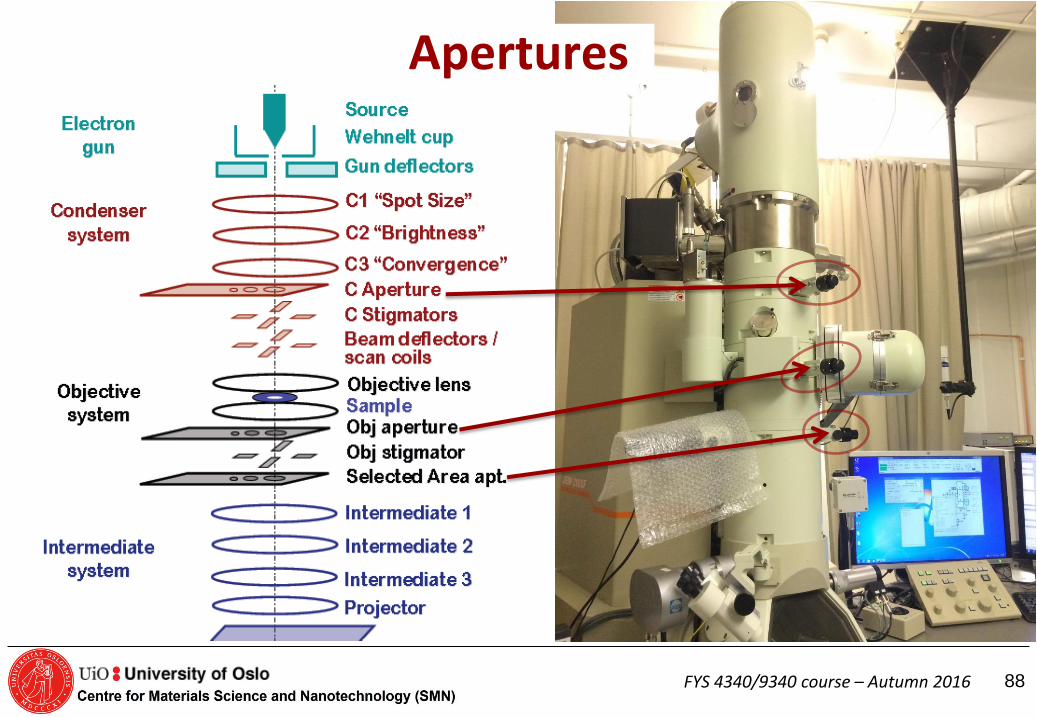
Apertures

Use of apertures Condenser aperture: Limit the beam divergence (reducing the diameter of the discs in the convergent electron diffraction pattern). Limit the number of electrons hitting the sample (reducing the intensity), . Objective aperture: Control the contrast in the image. Allow certain reflections to contribute to the image. Bright field imaging (central beam, 000), Dark field imaging (one reflection, g), High resolution Images (several reflections from a zone axis). Selected area aperture: Select diffraction patterns from small (> 1µm) areas of the specimen. Allows only electrons going through an area on the sample that is limited by the SAD aperture to contribute to the diffraction pattern (SAD pattern).
89 FYS 4340/9340 course – Autumn 2016

BF image
Objective aperture
Objective aperture: Contrast enhancement
All electrons contributes to the image.
Si
Ag and Pb
glue (light elements) hole
Only central beam contributes to the image.
Bright field (BF)
90 FYS 4340/9340 course – Autumn 2016

Small objective aperture Bright field (BF), dark field (DF) and weak-beam (WB)
BF image
Objective aperture
DF image Weak-beam
Dissociation of pure screw dislocation In Ni3Al, Meng and Preston, J. Mater. Scicence, 35, p. 821-828, 2000.
(Diffraction contrast)
91 FYS 4340/9340 course – Autumn 2016

Large objective aperture High Resolution Electron Microscopy (HREM)
HREM image
Phase contrast
92 FYS 4340/9340 course – Autumn 2016

Selected Area Diffraction Aperture Selected area diffraction
Objective lense
Diffraction pattern
Image plane
Specimen with two crystals (red and blue)
Parallel incoming electron beam
Selected area aperture
Pattern on the screen
93 FYS 4340/9340 course – Autumn 2016

Diffraction with no apertures Convergent beam and Micro diffraction (CBED and µ-diffraction)
Convergent beam
Focused beam
Convergent beam
Illuminated area less than
the SAD aperture size.
CBED pattern µ-diffraction pattern
C2 lens
Diffraction information from an area with
~ same thickness and crystal orientation
Small probe
94 FYS 4340/9340 course – Autumn 2016

Shadow imaging (diffraction mode)
Objective lense
Diffraction plane
(back focal plane)
Image plane
Sample
Parallel incoming electron beam
95 FYS 4340/9340 course – Autumn 2016

Specimen holders and goniometers
• Specimen holders
– Single tilt holders
– Double tilt holders
– Rotation holders
– Heating holders • Up to 800oC
– Cooling holders
• N: -100 - -150oC
• He: 4-10K
– Strain holders
– Environmental cells
• Goniometers:
- Side-entry stage - Most common type
- Eucentric
- Top-entry stage - Less obj. lens aberrations
- Not eucentric
- Smaller tilting angles
96 FYS 4340/9340 course – Autumn 2016

Next Lecture
97
• TEM Specimen Preparation
(Text book Chapters: 10)
FYS 4340/9340 course – Autumn 2016
Learning outcome
• HMS awareness
• Overview of common techniques
• Possible artifacts
• You should be able to evaluate which technique to use for a given sample
• Lab will give you some practical skills
98 FYS 4340/9340 course – Autumn 2016

What to consider before preparing a TEM specimen
• Ductile/fragile
• Bulk/surface/powder
• Insulating/conducting
• Heat resistant
• Irradiation resistant
• Single phase/multi phase
• Can mechanical damage be tolerated?
• Can chemical changes be accepted?
• Etc, etc…….
What is the objectiv of the TEM work?
99 FYS 4340/9340 course – Autumn 2016

Specimen preparation for TEM
• Crushing
• Cutting
– saw, “diamond” pen, ultrasonic drill, FIB
• Mechanical thinning
– Grinding, dimpling,
– Tripod polishing
• Electrochemical thinning
• Ion milling
• Coating
• Replica methods
• Etc.
100 FYS 4340/9340 course – Autumn 2016

SAFETY!!!!
• Know what you handling. – MSDS
• Protect your self and others around you. – Follow instructions
• If an accident occurs, know how to respond.
101 FYS 4340/9340 course – Autumn 2016

Safety rules
• Be sure that you can safely dispose of the waste product before you start.
• Be sure you have the ‘antidote’ at hand.
• Never work alone in the specimen-preparation laboratory.
• Always wear safety glasses when preparing specimens and/or full protective clothing, including face masks and gloves, if so advised by the safety manual.
• Only make up enough of the solution for the one polishing session. Never use a mouth pipette for measuring any component of the solution. Dispose of the solution after use.
• Always work in a fume hood when using chemicals.
• Check that the extraction rate of the hood is sufficient for the chemical used.
102 FYS 4340/9340 course – Autumn 2016
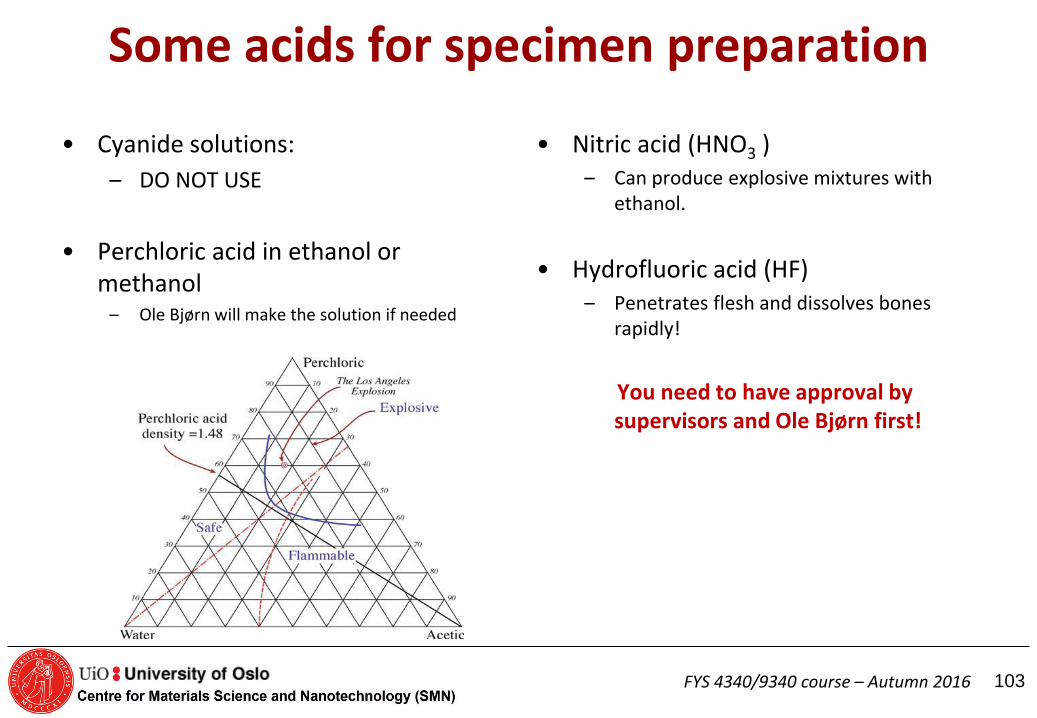
Some acids for specimen preparation
• Cyanide solutions:
– DO NOT USE
• Perchloric acid in ethanol or methanol
– Ole Bjørn will make the solution if needed
• Nitric acid (HNO3 ) – Can produce explosive mixtures with
ethanol.
• Hydrofluoric acid (HF) – Penetrates flesh and dissolves bones
rapidly!
You need to have approval by supervisors and Ole Bjørn first!
103 FYS 4340/9340 course – Autumn 2016

Work in the Stucture Physics lab
• Get the local HMS instructions from
Ole Bjørn Karlsen
Sign a form confirming that you have got the information
Ask
104 FYS 4340/9340 course – Autumn 2016

Preparation philosophy
Self-supporting discs or specimen supported on a grid or washer
105 FYS 4340/9340 course – Autumn 2016

Self-supporting disk or grid
• Self supporting disk
– Consists of one material • Can be a composite
– Can be handled with a tweeser
• Metallic, magnetic, non-magnetic, plastic, vacuum
If brittle, consider Cu washer with a slot
• Grid
– Several types (Fig. 10.3)
– Different materials (Cu, Ni…)
– Support brittle materials
– Support small particles
The grid may contribute to the EDS.
Common size: 3 mm.
Smaller specimen diameters can be used for certain holders.
106 FYS 4340/9340 course – Autumn 2016

Grids and washers used as specimen support
Common size: 3 mm. Smaller specimen diameters can be used for certain holders.
May contribute to the EDS
signal.
107 FYS 4340/9340 course – Autumn 2016

Preparation of self-supporting discs
• Cutting
– Ductile material or not?
• Grinding
– 100-200 μm thick
– polish
• Cut the 3mm disc
• Dimple ?
• Final thinning
– Ion beam milling
– Electropolishing
108 FYS 4340/9340 course – Autumn 2016
Self-supporting disk or grid
• Self supporting disk
– Consists of one material • Can be a composite
– Can be handled with a tweeser
• Metallic, magnetic, non-magnetic, plastic, vacuum
If brittle, consider Cu washer with a slot
• Grid and washer
– Several types
– Different materials (Cu, Ni…)
– Support brittle materials
– Support small particles
109 FYS 4340/9340 course – Autumn 2016

Preparation of self-supporting discs
• Cutting/cleaving
– Ductile material or not?
110 FYS 4340/9340 course – Autumn 2016

Cutting and cleaving
• Si
• GaAs
• NaCl
• MgO
Brittle materials with
well-defined cleavage plane
Razor blade or ultramicrotome
Cutting with a saw:
Soft or brittle material?
111

Preparation of self-supporting discs
• Cutting/cleaving
– Ductile material or not?
• Grinding
– 100-200 μm thick
– polish
• Cut the 3mm disc
112 FYS 4340/9340 course – Autumn 2016

Cutting a 3 mm disc
Soft or brittle material?
Mechanical damage OK?
Brittle: Spark erosion, ultrasonic drill, grinding drill
113 FYS 4340/9340 course – Autumn 2016

Preparation of self-supporting discs
• Cutting
– Ductile material or not?
• Grinding
– 100-200 μm thick
– polish
• Cut the 3mm disc
• Prethinning
– Dimpling
– Tripod polishing
114 FYS 4340/9340 course – Autumn 2016

Dimpling F
ω ΔΖ
115 FYS 4340/9340 course – Autumn 2016

Surface dimpling using a chemical solution
The light pipe permits visual detection of perforation using the mirror.
Si: HF + HNO3
GaAs: Br + methanol
116 FYS 4340/9340 course – Autumn 2016

Final thinning of the discs
• Electropolishing
• Ionmilling
117 FYS 4340/9340 course – Autumn 2016

Jet polishing
Twin-jet electropolishing apparatus. The positively charged specimen is held in a Teflon holder between the jets. A light pipe (not shown) detects perforation and terminates the polishing.
A single jet of gravity fed electrolyte thin a disk supported on a positively charged gauze. The disk has to be rotated periodically.
118 FYS 4340/9340 course – Autumn 2016

Ar ion beam thinning
Variation in penetration depth and thinning rate with the angle of incidence.
119 FYS 4340/9340 course – Autumn 2016

Effect of Ar-thinning on CdTe
Defects (dark spots) in Ar-thinned specimen Crystal thinned by reactive iodine ion milling.
120 FYS 4340/9340 course – Autumn 2016

first embedding them in epoxy and forcing the epoxy into a 3-mm (outside) diameter brass tube prior to curing the epoxy. The tube and epoxy are then sectioned into disks with a diamond saw, dimpled, and ion milled to transparency.
Preparation of particles and fibers
121 FYS 4340/9340 course – Autumn 2016

Spacers : Si, glass, or some other inexpensive material.
Initial preparation steps
122
THIN FILMS TEM specimen preparation
FYS 4340/9340 course – Autumn 2016

Grind down/
dimple
THIN FILMS TEM specimen preparation
• Top view
• Cross section
or
Cut out a cylinder
and glue it in a Cu-tube
Grind down and
glue on Cu-rings
Cut a slice of the
cylinder and grind
it down / dimple
Ione beam thinning
Cut out cylinder
Ione beam thinning
Cut out slices
Glue the interface
of interest face to
face together with
support material
Cut off excess
material
• Focused Ion Beam
(FIB)
123 FYS 4340/9340 course – Autumn 2016

• Electropolishing – The window method
• Ultramicrotomy
• Crushing – In ethanol
– Mix in an epoxy
• Replication and extraction
• Cleaving and SACT
• The 90o wedge
• Lithography
• Preferensial chemical etching
Specimens on grids/washers
124 FYS 4340/9340 course – Autumn 2016

Window polishing
• A sheet of the metal 100mm2 is lacquered around the edges and made the anode of an electrolytic cell. • Progress during thinning: the initial perforation
usually occurs at the top of the sheet; lacquer is used to cover the initial perforation and the sheet is rotated 180o and thinning continues to ensure that final thinning occurs near the center of the sheet.
125 FYS 4340/9340 course – Autumn 2016

Ultramicrotomy
The sample is first embedded in epoxy or some other medium or the whole sample is clamped and moved across a knife edge. The thin flakes float off onto water or an appropriate inert medium, from where they are collected on grids.
126 FYS 4340/9340 course – Autumn 2016

Replication of a surface
1) Spray acetone on the surface to be replicated before pressing a plastic (usually cellulose acetate) 2) Removed the plastic from the surface when hardened 3) Evaporate a C, Cr, or Pt film onto the replicated plastic surface. 4) Dissolve the plastic with acetone Alternatively: the direct carbon replica.
127 FYS 4340/9340 course – Autumn 2016

Extraction replication
The rest of the matrix is etched A thin amorphous carbon film is evaporated over the particles
128 FYS 4340/9340 course – Autumn 2016

Cleaving
Cleaved MoS2 showing regions of different shades of green, which correspond to different thicknesses.
1) Use tape
2) Dissolve tape in a
solvent
129 FYS 4340/9340 course – Autumn 2016

SACT The small-angle cleaving technique
Invaluable for films on Si or glass where there is no crystal structure
1. Scratch the sample; 2. Cleaving along the scratch;
130 FYS 4340/9340 course – Autumn 2016

LACT- The 90o wedge
1) Prethin: 2-mm square of the multilayers on a Si substrate 2) Scribe the Si through the surface layers, turn over, and cleave Need: a sharp 90o edge; 3) Mount the 90o corner
131 FYS 4340/9340 course – Autumn 2016

Preferential chemical etching
Etch away most of the sample, leaving a small etched plateau Mask a region <50 nm across and etch away the majority of the surrounding plateau. Turn 90o and mounted in a specimen holder
132 FYS 4340/9340 course – Autumn 2016

Lithographic techniques
Etching between the barrier layers Produces an undercutting down to the implanted layer which acts as an etch stop, producing a uniform layer 10 mm thick.
133 FYS 4340/9340 course – Autumn 2016

FIB
Schematic of a two-beam (electron and ion) FIB instrument.
-The area of interest has been marked. -A Pt bar is deposited to protect this area from the Ga beam. -The two trenches are cut. -The bottom and sides of the slice are (final) cut. -The TEM specimen is polished in place before extracting it.
134 FYS 4340/9340 course – Autumn 2016

A dual-beam FIB instrument.
135 FYS 4340/9340 course – Autumn 2016

Summary flow chart for specimen preparation
136 FYS 4340/9340 course – Autumn 2016
Next Lecture
137
• Introduction to Crystallography
by
Patricia Almeida Carvalho Senior Research Scientist
SINTEF
THERE WILL BE TEM COURSE LAB THIS THURSDAY
***