Total solder points: 274 Difficulty level: beginner 1 2 3 ...

EAA SOLIDWORKS University p 1/14
Modeling an Aircraft Airfoil Tutorial
Difficulty: Beginner | Time: 1 hour
This modeling lesson guides you through the creation of an aircraft airfoil in SOLIDWORKS, then using the airfoil to create
an aerodynamic surface.
You will create two airfoils and use them to create a simple wing panel, but the process can be easily modified for any
number of applications such as tail fins, streamlined struts and fairings.
The objective of the lesson is to give you an understanding of the basic workflow and tools to create your own wing skin
in the future.
In this lesson you will learn these skills:
Create an airfoil in a spreadsheet
Importing a curve into SOLIDWORKS to create an airfoil
Create a Sketch Block and loft feature to create a simple wing
Process Overview
Designing an airfoil is relatively straightforward process:
1. Locate your airfoil coordinate data (X/Y/Z coordinates),
2. Manipulate airfoil data for to scale and ensure completeness,
3. Import airfoil coordinate data into SOLIDORKS as a Curve Through XYZ,
4. Use curves to loft an aerodynamic surface,
Due to tutorial time considerations, the first two steps are taken care for you.
Locating Your Airfoil Coordinate Data
You can copy airfoil coordinates from public websites such as – UIUC Airfoil Coordinates Database (http://m-
selig.ae.illinois.edu/ads/coord_database.html), or The Incomplete Guide to Airfoil Usage (http://m-
selig.ae.illinois.edu/ads/aircraft.html).
EAA SOLIDWORKS University p 2/14
Modeling an Aircraft Airfoil Tutorial
You can also purchase airfoil design software such as Profili 2 (http://www.profili2.com ) which enables you to mix and
match thickness and camber profiles to make your own unique shape.
Manipulating Airfoil Data
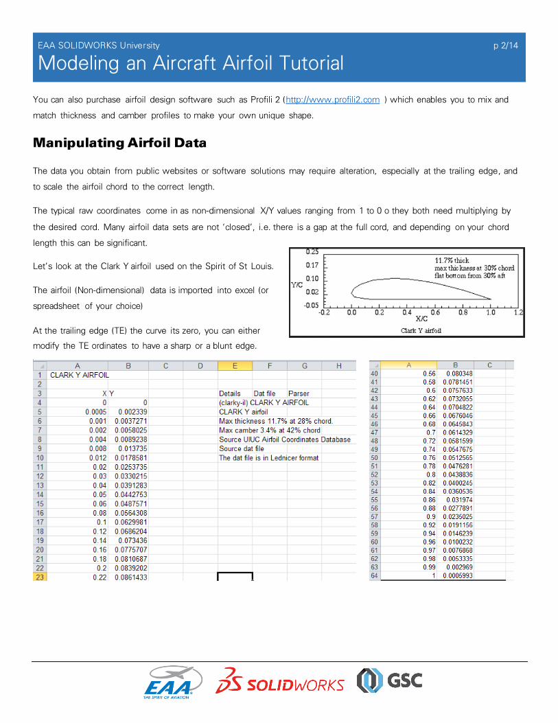
The data you obtain from public websites or software solutions may require alteration, especially at the trailing edge, and
to scale the airfoil chord to the correct length.
The typical raw coordinates come in as non-dimensional X/Y values ranging from 1 to 0 o they both need multiplying by
the desired cord. Many airfoil data sets are not ‘closed’, i.e. there is a gap at the full cord, and depending on your chord
length this can be significant.
Let’s look at the Clark Y airfoil used on the Spirit of St Louis.
The airfoil (Non-dimensional) data is imported into excel (or
spreadsheet of your choice)
At the trailing edge (TE) the curve its zero, you can either
modify the TE ordinates to have a sharp or a blunt edge.

EAA SOLIDWORKS University p 3/14
Modeling an Aircraft Airfoil Tutorial
SOLIDWORKS needs three ordinates to locate a point in space (X/Y/Z) so you need to
create a second sheet with the ordinates multiplied by your airfoil chord width, (X & Y),
with a third column of zeros (Z-axis).
It is important to note that the units of your airfoil are set on import not in the excel sheet,
but you should ensure that the units between the excel sheet and SOLIDWORKS are
consistent.
Once you have the .dat file formatted correctly, save the sheet as a .txt file ready for
importing into SOLIDWORKS.
Creating an Airfoil in SOLIDWORKS
1. Select Fi le \ New on the top menu. (If this is the first document you have created, the Units and Dimension Standard
dialog box appears.)
a. For Units, select IPS (inch, pounds, seconds).
b. For Dimension Standard, select ANSI .
c. Click OK.
The New SOLIDWORKS Document dialog box appears.
2. Select Part, and click OK. A new part window appears.
3. Import airfoil curve data. Select Insert\Curves\Curve through XYZ
4. In the dialog box that appears, browse to the folder
‘Airfoil curve data’, then change the curve file type
to “.txt”.

EAA SOLIDWORKS University p 4/14
Modeling an Aircraft Airfoil Tutorial
5. Select the Root Upper curve and open, Then select ok
6. Repeat to import the Root Lower .txt file to finalize the airfoil.

EAA SOLIDWORKS University p 5/14
Modeling an Aircraft Airfoil Tutorial
Create Airfoil Sketch
7. Select the Sketch toolbar Icon and Click Sketch.
8. Select the Front plane.
9. From the sketch toolbar select the Convert Entities tool and select your top and bottom X, Y, Z curves..
10. Select the green check box.
11. Select the zoom to area from the mini tool bar.
12. Window into the the airfoil trailing edge. You can see the gap. Select the Line tool to connect the to end
points. Zoom in closer if necessary.
13. You can tell if the curve is closed if your TE section becomes shaded.
14. Hit the Esc key to exit the line command, and select the zoom
to fit from the mini tool bar.

EAA SOLIDWORKS University p 6/14
Modeling an Aircraft Airfoil Tutorial
15. Add a chord center line to your airfoil; use the centerline option of the line tool.
16. Draw a horizontal centerline from the leading edge to beyond the trailing edge.
a. Start from the LE, right mouse click, and
move the mouse to the right to extend
the line.
b. Click again to finish the line. You will see
that the line is horizontal by the – icon as
you extend the line
c. Hit Esc to exit the command.
17. To make it easier to use this airfoil later we are going to group
these sketch entities into a Sketch Block.
a. Select Tool \ Blocks \ Make
b. Now, window-select the airfoil, ensuring all lines are within
the selection, as shown below.
c. You should have four entities in the section box. Select the green check mark.

EAA SOLIDWORKS University p 7/14
Modeling an Aircraft Airfoil Tutorial
18. Exit the sketch by selecting the sketch return icon in the top left corner.
19. Save the part to the desktop with the name Airfoil_<your initials\
20. Looking at the model tree you can see the two imported curves, the first sketch,
and the Sketch block.
21. The Sketch block is what we will use to build the wing so we have to save
the block out of the part.
a. Right mouse click on the block and select save block.
b. Save the block to the desktop with the name <your
initials\_RooT_Block1.SLDBLK
22. Now, create the wing tip airfoil using the same method, from importing the curves to saving the sketch block.
23. Now, save the part.
Creating a Simple Wing
In this simple wing we will add dihedral by creating a new sketch plane at an angle to the top plane.
1. Click Fi le \ New \ Part.
2. Click OK.
3. Select the Feature tab of the command bar.
4. Select the Reference Geometry command.

EAA SOLIDWORKS University p 8/14
Modeling an Aircraft Airfoil Tutorial
5. Select Axis.
6. Select the top and Front reference planes. If the planes are not visible in the modeling window select the arrow next
to the part name and select from the model feature list.
7. Select the Reference Geometry command again.
8. Select Plane.
9. Select the Top Plane as the first reference, and the Axis as the second reference. If the planes are not visible in the
modeling window select the arrow next to the part name and select from the model feature list.
10. Select the angle button in the first reference and set the value as 3-degrees.
11. Select the green check mark to accept the settings.
12. Select the Sketch toolbar
13. Click Sketch.
14. Select Plane 1 plane. A sketch opens on the Plane 1
plane.
15. Sketch and dimension the wing plan.
a. Draw a horizontal line 84 inches long from the origin:
Select Line
b. Start from the center, click, and move the mouse to
the right to extend this line. Click again to finish the
line. You will again see that the line is horizontal by the – icon as you extend the line.
c. Select the Smart Dimension , ”select” the line and place the linear dimension.
d. The modify dimension dialogue is now displayed, type in 84

EAA SOLIDWORKS University p 9/14
Modeling an Aircraft Airfoil Tutorial
16. Add a 200-inch vertical line from the origin. You will know the line is vertical from
the | icon. Convert to construction geometry by right mouse click and select
Construction Geometry.
17. Add three more lines to complete the outline of the wing plan.

EAA SOLIDWORKS University p 10/14
Modeling an Aircraft Airfoil Tutorial
18. Set the semi span of the wing by selecting the end point of the construction line and the horizontal line and setting a
coincident constraint and add the following dimensions
19. Accept the sketch.
20. Save the part as <your initials\_simple_wing to the desktop.
Add Wing Root and Tip Planes
The wing airfoils should be orientated perpendicular to the wing plan.
1. Select the Reference Geometry command.
Select Plane and select Plane-1 as the first
reference and the axis as the second reference.
The default orientation (Perpendicular) is
correct. Accept the dialogue box.
2. Select the Reference Geometry command. Select
Plane. Select Plane-2 and a point at the wing tip of
the wing plan sketch. Accept the command

EAA SOLIDWORKS University p 11/14
Modeling an Aircraft Airfoil Tutorial
Add Sketch Blocks for the Wing Root and Wing Tip
1. Create a sketch on Plane-2 by RMC on it and select the Sketch icon from the mini toolbar.
2. Select Tools \ B locks \ Insert B lock.
3. Browse to the root airfoil on the desktop.
4. Place the sketch block with a right mouse click.
5. Hit the Esc key to close the sketch block inert dialogue box.
6. Locate the sketch block by selecting the point at the airfoil LE
and the sketch origin and setting a coincident constraint.

EAA SOLIDWORKS University p 12/14
Modeling an Aircraft Airfoil Tutorial
7. In this wing the Root angle is zero degrees so select the airfoil
cord and the wing plan line and set a collinear constraint.
8. Accept the sketch to exit.
9. Create a sketch on Plane-3 by right mouse click on it and select the Sketch icon from the mini toolbar.
10. Select Tools \ B locks \ Insert Block.
11. Browse to the wing tip airfoil on the desktop.
12. Place the sketch block with a right mouse click.

EAA SOLIDWORKS University p 13/14
Modeling an Aircraft Airfoil Tutorial
13. Hit Esc to close the sketch block inert dialogue box.
14. Locate the sketch block by selecting the point at the airfoil LE and the sketch origin and setting a coincident constraint
at the wing tip we want a negative airfoil angle of attack.
15. Add an angular dimension of 3-degrees between the airfoil chord and the wing planform sketch line. Exit the sketch.
Creating the Wing
The wing is created by a loft feature between the root and tip sketches -
1. Select Lofted Boss/Base from the features command bar.
.
2. Select the top curve of the root profile sketch.
3. Select the top curve of the tip profile sketch.

EAA SOLIDWORKS University p 14/14
Modeling an Aircraft Airfoil Tutorial
The wing is now shown in preview.
4. Select the green check mark to accept the loft. Congratulations you have created a simple wing! The same process
can be used for other aerodynamic surfaces and fairings. Additional features can be added to round off the wing tip
and trailing edge.