DIFFERENTIAL TEMPERATURE CONTROLLER FOR SIMPLE …
18
Control of simple solar thermal plants with 1 collector array and 1 tank - Full graphic display for clear and logical visualization - Innovative operation concept for easy handling - Smart and time-saving wiring concept - Installation wizard for safe commissioning - Service wizard for targeted and quick customer service - Numerous operation, protective as well as monitoring and service functions - Attractive, elegant and puristic design - Various equipment levels for different applications CUSTOMER BENEFIT DIFFERENTIAL TEMPERATURE CONTROLLER FOR SIMPLE SOLAR THERMAL PLANTS FOR DRINKING WATER HEATING AND HEATING SUPPORT
Transcript of DIFFERENTIAL TEMPERATURE CONTROLLER FOR SIMPLE …
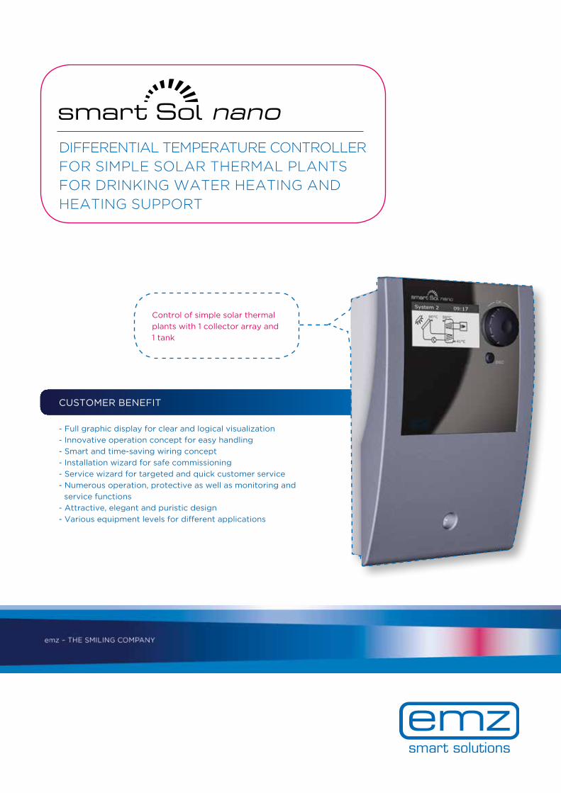
Control of simple solar thermal plants with 1 collector array and 1 tank
- Full graphic display for clear and logical visualization - Innovative operation concept for easy handling - Smart and time-saving wiring concept - Installation wizard for safe commissioning - Service wizard for targeted and quick customer service - Numerous operation, protective as well as monitoring and service functions - Attractive, elegant and puristic design - Various equipment levels for different applications
CUSTOMER BENEFIT
DIFFERENTIAL TEMPERATURE CONTROLLER FOR SIMPLE SOLAR THERMAL PLANTS FOR DRINKING WATER HEATING AND HEATING SUPPORT

Solar controllers - equipment levels B Basic S Special
EQUIPMENT LEVELS
Hardware
Number inputs for temperature sensors PT1000 3 3
thereof switchable (analog outputs 0...10V or PWM outputs or temperature inputs) - -
thereof usable as input for pulse encoder/impeller - -
Number inputs (male connectors) for analog vortex flow sensors - -
Number triac outputs, max. 1A - for pumps, valves, boiler 1 1
Number relay outputs - change-over contact, pot.-free, max. 1A - for pumps, valves, boiler - -
Number high current relay outputs - make contact, pot.-free, max. 15A - for immersion heater, boiler - 1
Number fixed analog outputs 0…10V or PWM outputs for high-efficiency pumps 1 1
Additional supply terminals, 2 x 85V-265V for valves, 5V and 24V for sensors - -
SD card slot for data logging, upload of hydraulic systems incl. settings - -
USB port for acces to SD card, PC, remote access and software update - -
Acoustic alarm (to be deactivated) in case of messages - -
Power reserve for real-time clock (min. 8 h) √ √
Energy-saving switch power supply with a wide-range input, 85 … 265VAC, 50/60Hz - -
Transformer power supply, 230VAC +/-10%, 50/60Hz √ √
Full graphic TFT colour display with backlight, dimmable - -
Full graphic FSTN monochrome display with backlight √ √
B S
System
Multi-piece plastic housing √ √
Operation via rotary encoder and esc button √ √
Micro fuse incl. spare fuse, type 5x20mm, time-lag 2A 2A
Laser engraved connection diagram on the rear side of the terminal cover √ √
Wall mounting, installation in pump group or tank √ √
Protection class IP20 √ √
Ambient temperature 0 … 40°C √ √
Active display area, width x height in mm 45 x 23 45 x 23
Mesaurements, width x height x depth in mm 102 x 150 x 45 102 x 150 x 45
Maximum number national languages 15 15
Maximum number collector arrays 1 1
Maximum number tanks 1 1
Number hydraulic systems with animation of pumps, valves, back-up heating/disable recharge 1 3
Installation wizard (free configuration, selection hydraulic system, upload from SD card) √ √
Preset of configuration at OEM level √ √
Service wizard √ √
Solar heating support √ √
Protective functions
Collector emergency OFF adjustable √ √
Collector cooling √ √
Antifreeze √ √
Tank maximum temperature limitation √ √
Tank temperature limit cut-out √ √
Anti-blocking protection √ √
Soft charge - -
Tank cooling √ √
Operation and efficiency functions
Differential temperature control (Delta-T-control) √ √
Fixed temperature control (Fixed-T-control) √ √
Disable the tank recharge with graphical display - -
Efficient tank charge - -

Solar controllers - equipment levels B S
Monitoring and Service functions
Sensor monitoring √ √
Monitoring the output parameters √ √
Permanent plausibility checks with detection of missing and unplausible settings √ √
Sensor balancing √ √
Display free tank sensor top √ √
Service hour counter for outputs √ √
Data logging on SD card, upload hydraulic systems - -
Display of temperatures and actuators √ √
Message list with indication of errors and warnings √ √
Manual Mode √ √
Reset of complete or parameter related factory settings √ √
Solar yield calculation via pump activation with data display √ √
Solar yield measurement via vortex and/or impeller with data display - -
Graphical representation of the solar yield on the display (from SD card or RAM) - -
Number of heat meters for solar yield determination 1 1
Display of CO²-savings - -
Optional accessory and customized adaptions on request
Assembly/operating instructions on CD, safety instructions as a leaflet √ √
Assembly/operating instructions incl. safety instructions as a booklet √ √
Quick Start Guide as a leaflet √ √
Collector sensor PT1000, grey Silicon, operation temperature range -40 … +180°C, length 2.500mm, with ferrules
√ √
Tank sensor PT1000, black PVC, operation temperature range -5 … +90°C, length 2.500mm, with ferrules
√ √
Power cable, black 230V, 3poles, H05VV-F 3G0,75mm, length 1.500mm, with ferrules
√ √
SD card - -
Vortex flow sensors, Grundfos types VFS - -
Impeller flow sensors - -
Resistors for disable tank recharge or sensor switching, boiler sensor PT100 = 130 Ω / PT500 = 620 Ω / PT1000 = 1,3 kΩ
- -
smart Box for easy remote access via internet: graphical visualization of the log-data, parameterization, software update, online operation
- -
Local PC software "smart Sol analyzer" for direct connection: graphical visualization of the log-data, parameterization, software update, online operation
- -
OEM personalization √ √
Priority/pendulum charging at multiple tanks/zone tanks with adjustable priorities and temperatures - -
Low-flow-function for low-flow-plants - -
Tube collector function √ √
Selectable thermostat functions - -
Maximum number of freely selectable control functions - -
Speed control and speed limitation of the pumps √ √
Collector defrosting - -
Holiday function - -
Automatic summer/winter time changeover - -
Collector minimum temperature √ √
Overtravel time for outputs √ √
Quick charging - -
Inversion of valve signal via menue setting - -
Anti-legionella function in conjunction with back-up heating - √
Back-up heating via different heat sources - √
Direct back-up heating via electric immersion heater - √
Heating return increase - -
Bypass in the solar circuit - -

1.1 Evaluation
Heat quantities
Measured valuesService hours
Error list
0.9 End
Next
You have completedcommissioning!
emz-Hanauer GmbH & Co. KGaASiemensstraße 1D-92507 Nabburg
Telefon: +49 (0) 9433 898-0Fax: +49 (0) 9433 898-188
OPERATION AND VISUALIZATION
- Full graphic FSTN monochrome display with backlight - Rotary encoder with Push, ESC button - Different operation levels for OEM , heating installer and end user - Self-explanatory menu and user guidance - Combination of plain text displays and symbols - Graphical representation of active functions - Different national languages
WIRING
- Easily removable terminal cover for access to the terminal compartment - Laser engraved connection diagram on the rear side of the terminal cover - Generously dimensioned terminal compartment - Proven spring-type terminals - Convenient, intersection-free wiring - Strain relief device
INSTALLATION AND SERVICE WIZARD
- Developed in common with Regensburg University and heating trade - Solar thermal plant is ready to operate with just a few settings - By selecting the plant systems all procedures and functions are preset - Optical indications of malfunctions and errors - Possibility of a preliminary diagnosis by the enduser in case of error messages - Recommendations for the installer to eliminate malfunction or to perform maintenance work
PLANT VISUALIZATION
- Indication of measured values for inputs and outputs - Service hour counter for outputs - Message list with indication of errors and warnings - Solar yield calculation via pump activation with data display
AS
Auxiliary heating circuitTank sensor 1, top
Collector sensor 1
Tank sensor 1, bottom
Connection to power supply
Solar circuit pump 1
HYDRAULIC SYSTEMS
Ver
sio
n: E
N 0
2/20
17
Message list
BS S S
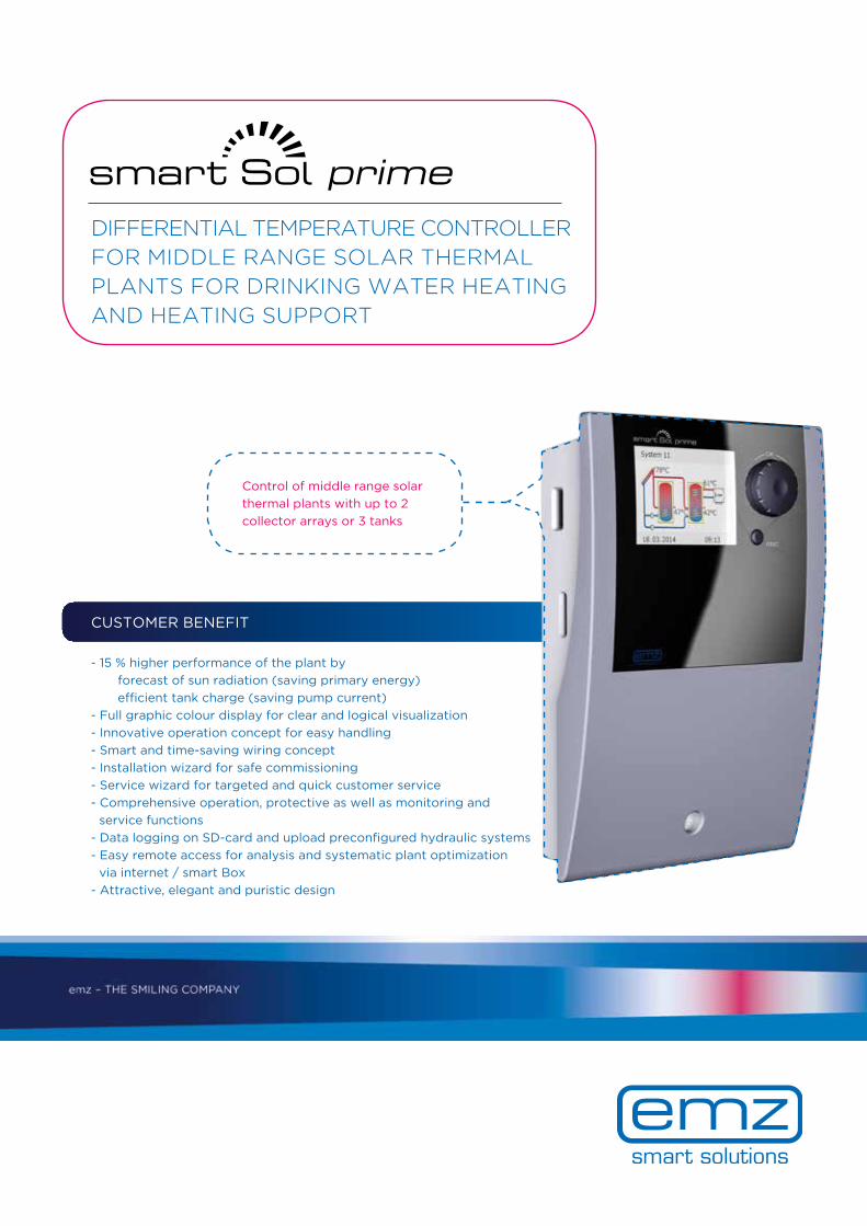
Control of middle range solar thermal plants with up to 2 collector arrays or 3 tanks
CUSTOMER BENEFIT
DIFFERENTIAL TEMPERATURE CONTROLLER FOR MIDDLE RANGE SOLAR THERMAL PLANTS FOR DRINKING WATER HEATING AND HEATING SUPPORT
- 15 % higher performance of the plant by forecast of sun radiation (saving primary energy) efficient tank charge (saving pump current) - Full graphic colour display for clear and logical visualization - Innovative operation concept for easy handling - Smart and time-saving wiring concept - Installation wizard for safe commissioning - Service wizard for targeted and quick customer service - Comprehensive operation, protective as well as monitoring and service functions - Data logging on SD-card and upload preconfigured hydraulic systems - Easy remote access for analysis and systematic plant optimization via internet / smart Box - Attractive, elegant and puristic design

T TopC Comfort
Hardware
Number inputs for temperature sensors PT1000 4 6
thereof switchable (analog outputs 0...10V or PWM outputs or temperature inputs) 1 1
thereof usable as input for pulse encoder/impeller 2 2
Number inputs (male connectors) for analog vortex flow sensors - 1
Number triac outputs, max. 1A - for pumps, valves, boiler 2 2
Number relay outputs - change-over contact, pot.-free, max. 1A - for pumps, valves, boiler 1 1
Number high current relay outputs - make contact, pot.-free, max. 15A - for immersion heater, boiler - -
Number fixed analog outputs 0…10V or PWM outputs for high-efficiency pumps - 2
Additional supply terminals, 2 x 85V-265V for valves, 5V and 24V for sensors - -
SD card slot for data logging, upload of hydraulic systems incl. settings - √
USB port for acces to SD card, PC, remote access and software update - √
Acoustic alarm (to be deactivated) in case of messages √ √
Power reserve for real-time clock (min. 8 h) √ √
Energy-saving switch power supply with a wide-range input, 85 … 265VAC, 50/60Hz - -
Transformer power supply, 230VAC +/-10%, 50/60Hz √ √
Full graphic TFT colour display with backlight, dimmable √ √
Full graphic FSTN monochrome display with backlight - -
EQUIPMENT LEVELS
Solar controllers - equipment levels C T
System
Multi-piece plastic housing √ √
Operation via rotary encoder and esc button √ √
Micro fuse incl. spare fuse, type 5x20mm, time-lag 2A 2A
Laser engraved connection diagram on the rear side of the terminal cover √ √
Wall mounting, installation in pump group or tank √ √
Protection class IP20 √ √
Ambient temperature 0 … 40°C √ √
Active display area, width x height in mm 47 x 35 47 x 35
Mesaurements, width x height x depth in mm 115 x 173 x 46 115 x 173 x 46
Maximum number national languages 20 20
Maximum number collector arrays 2 2
Maximum number tanks 2 3
Number hydraulic systems with animation of pumps, valves, back-up heating/disable recharge 20 24
Installation wizard (free configuration, selection hydraulic system, upload from SD card) √ √
Preset of configuration at OEM level √ √
Service wizard √ √
Solar heating support √ √
Protective functions
Collector emergency OFF adjustable √ √
Collector cooling √ √
Antifreeze √ √
Tank maximum temperature limitation √ √
Tank temperature limit cut-out √ √
Anti-blocking protection √ √
Soft charge √ √
Tank cooling √ √
Operation and efficiency functions
Differential temperature control (Delta-T-control) √ √
Fixed temperature control (Fixed-T-control) √ √
Disable the tank recharge with graphical display √ √
Efficient tank charge √ √

Solar controllers - equipment levels C T
Monitoring and Service functions
Sensor monitoring √ √
Monitoring the output parameters √ √
Permanent plausibility checks with detection of missing and unplausible settings √ √
Sensor balancing √ √
Display free tank sensor top √ √
Service hour counter for outputs √ √
Data logging on SD card, upload hydraulic systems - √
Display of temperatures and actuators √ √
Message list with indication of errors and warnings √ √
Manual Mode √ √
Reset of complete or parameter related factory settings √ √
Solar yield calculation via pump activation with data display √ √
Solar yield measurement via vortex and/or impeller with data display √ √
Graphical representation of the solar yield on the display (from SD card or RAM) √ √
Number of heat meters for solar yield determination 2 2
Display of CO²-savings √ √
Optional accessory and customized adaptions on request
Assembly/operating instructions on CD, safety instructions as a leaflet √ √
Assembly/operating instructions incl. safety instructions as a booklet √ √
Quick Start Guide as a leaflet √ √
Collector sensor PT1000, grey Silicon, operation temperature range -40 … +180°C, length 2.500mm, with ferrules
√ √
Tank sensor PT1000, black PVC, operation temperature range -5 … +90°C, length 2.500mm, with ferrules
√ √
Power cable, black 230V, 3poles, H05VV-F 3G0,75mm, length 1.500mm, with ferrules
√ √
SD card - √
Vortex flow sensors, Grundfos types VFS - √
Impeller flow sensors √ √
Resistors for disable tank recharge or sensor switching, boiler sensor PT100 = 130 Ω / PT500 = 620 Ω / PT1000 = 1,3 kΩ
√ √
smart Box for easy remote access via internet: graphical visualization of the log-data, parameterization, software update, online operation
- √
Local PC software "smart Sol analyzer" for direct connection: graphical visualization of the log-data, parameterization, software update, online operation
- √
OEM personalization √ √
Priority/pendulum charging at multiple tanks/zone tanks with adjustable priorities and temperatures √ √
Low-flow-function for low-flow-plants √ √
Tube collector function √ √
Selectable thermostat functions √ √
Maximum number of freely selectable control functions 2 2
Speed control and speed limitation of the pumps √ √
Collector defrosting √ √
Holiday function √ √
Automatic summer/winter time changeover √ √
Collector minimum temperature √ √
Overtravel time for outputs √ √
Quick charging √ √
Inversion of valve signal via menue setting √ √
Anti-legionella function in conjunction with back-up heating √ √
Back-up heating via different heat sources √ √
Direct back-up heating via electric immersion heater - -
Heating return increase √ √
Bypass in the solar circuit √ √

emz-Hanauer GmbH & Co. KGaASiemensstraße 1D-92507 Nabburg
Telefon: +49 (0) 9433 898-0Fax: +49 (0) 9433 898-188
QRCODE
emz-Hanauer GmbH & Co. KGaASiemensstraße 1D-92507 Nabburg
Telefon: +49 (0) 9433 898-0Fax: +49 (0) 9433 898-188
Tank sensor 2, bottom
Tank sensor 2, topS olar circuit pump 2
Connection to power supply
Collector sensor 1
Solar circuit pump 1Tank sensor 1, bottom
heating boiler connection according to
page 45-46
OPERATION AND VISUALIZATION
- Full graphic TFT colour display with backlight - Rotary encoder with Push, ESC button - Different operation levels for OEM, heating installer and end user - Self-explanatory menu and user guidance - Combination of plain text displays and symbols - Graphical representation of active functions - Different national languages
WIRING
- Easily removable terminal cover for access to the terminal compartment - Laser engraved connection diagram on the rear side of the terminal cover - Generously dimensioned terminal compartment - Variable wiring and connection possibilities - Proven spring-type terminals - Convenient, intersection-free wiring - Strain relief device
INSTALLATION AND SERVICE WIZARD
- Developed in common with Regensburg University and heating trade - Solar thermal plant is ready to operate with just a few settings - Commissioning via free configuration, selection of the hydraulic system or upload from the SD card - Optical and/or acustical indications of malfunctions and errors - Possibility of a preliminary diagnosis by the enduser in case of error messages - Recommendations for the installer to eliminate malfunction or to perform maintenance work
PLANT VISUALIZATION
- Indication of measured values for inputs and outputs - Service hour counter for outputs - Display CO²-savings - Message list with indication of errors and warnings - Solar yield measurement with data display and graphical representation - Remote access plus software packages for plant monitoring and optimization
DATA INTERFACES
- Data interfaces such as SD card for data logging and commissioning or USB for remote control and software update
HYDRAULIC SYSTEMS
Ver
sio
n: E
N 0
2/20
17
CT
CT
CT
CT
CT
CT
CT
CT
CT
= (smart sol prime "Comfort") and operation of a HE pump via PWM output are only systems with one pump and up to 3 temperature sensors possible!"
C
CT
CT
CT
CT
CT
CT
CT
CT
CT
CT
CT T
TTT

Control of complex solar thermal plants with up to 2 collector arrays or 4 tanks
- 15 % higher performance of the plant by forecast of sun radiation (saving primary energy) efficient tank charge (saving pump current) - Full graphic colour display for clear and logical visualization - Innovative operation concept for easy handling - Smart and time-saving wiring concept - Installation wizard for safe commissioning - Service wizard for targeted and quick customer service - Comprehensive operation, protective as well as monitoring and service functions - Data logging on SD-card and upload preconfigured hydraulic systems - Easy remote access for analysis and systematic plant optimization via internet / smart Box - Attractive, elegant and puristic design
CUSTOMER BENEFIT
DIFFERENTIAL TEMPERATURE CONTROLLER FOR COMPLEX SOLAR THERMAL PLANTS FOR DRINKING WATER HEATING AND HEATING SUPPORT

P Premium
Hardware
Number inputs for temperature sensors PT1000 10
thereof switchable (analog outputs 0...10V or PWM outputs or temperature inputs) 4
thereof usable as input for pulse encoder/impeller 4
Number inputs (male connectors) for analog vortex flow sensors 2
Number triac outputs, max. 1A - for pumps, valves, boiler 4
Number relay outputs - change-over contact, pot.-free, max. 1A - for pumps, valves, boiler 1
Number high current relay outputs - make contact, pot.-free, max. 15A - for immersion heater, boiler -
Number fixed analog outputs 0…10V or PWM outputs for high-efficiency pumps -
Additional supply terminals, 2 x 85V-265V for valves, 5V and 24V for sensors √
SD card slot for data logging, upload of hydraulic systems incl. settings √
USB port for acces to SD card, PC, remote access and software update √
Acoustic alarm (to be deactivated) in case of messages √
Power reserve for real-time clock (min. 8 h) √
Energy-saving switch power supply with a wide-range input, 85 … 265VAC, 50/60Hz √
Transformer power supply, 230VAC +/-10%, 50/60Hz -
Full graphic TFT colour display with backlight, dimmable √
Full graphic FSTN monochrome display with backlight -
Solar controllers - equipment level
System
Multi-piece plastic housing √
Operation via rotary encoder and esc button √
Micro fuse incl. spare fuse, type 5x20mm, time-lag 4A
Laser engraved connection diagram on the rear side of the terminal cover √
Wall mounting, installation in pump group or tank √
Protection class IP20 √
Ambient temperature 0 … 40°C √
Active display area, width x height in mm 70 x 53
Mesaurements, width x height x depth in mm 218 x 218 x 51
Maximum number national languages 20
Maximum number collector arrays 2
Maximum number tanks 4
Number hydraulic systems with animation of pumps, valves, back-up heating/disable recharge 30
Installation wizard (free configuration, selection hydraulic system, upload from SD card) √
Preset of configuration at OEM level √
Service wizard √
Solar heating support √
Protective functions
Collector emergency OFF adjustable √
Collector cooling √
Antifreeze √
Tank maximum temperature limitation √
Tank temperature limit cut-out √
Anti-blocking protection √
Soft charge √
Tank cooling √
Operation and efficiency functions
Differential temperature control (Delta-T-control) √
Fixed temperature control (Fixed-T-control) √
Disable the tank recharge with graphical display √
Efficient tank charge √
EQUIPMENT LEVELS
P

Solar controllers - equipment levels
Monitoring and Service functions
Sensor monitoring √
Monitoring the output parameters √
Permanent plausibility checks with detection of missing and unplausible settings √
Sensor balancing √
Display free tank sensor top √
Service hour counter for outputs √
Data logging on SD card, upload hydraulic systems √
Display of temperatures and actuators √
Message list with indication of errors and warnings √
Manual Mode √
Reset of complete or parameter related factory settings √
Solar yield calculation via pump activation with data display √
Solar yield measurement via vortex and/or impeller with data display √
Graphical representation of the solar yield on the display (from SD card or RAM) √
Number of heat meters for solar yield determination 4
Display of CO²-savings √
Optional accessory and customized adaptions on request
Assembly/operating instructions on CD, safety instructions as a leaflet √
Assembly/operating instructions incl. safety instructions as a booklet √
Quick Start Guide as a leaflet √
Collector sensor PT1000, grey Silicon, operation temperature range -40 … +180°C, length 2.500mm, with ferrules
√
Tank sensor PT1000, black PVC, operation temperature range -5 … +90°C, length 2.500mm, with ferrules
√
Power cable, black 230V, 3poles, H05VV-F 3G0,75mm, length 1.500mm, with ferrules
√
SD card √
Vortex flow sensors, Grundfos types VFS √
Impeller flow sensors √
Resistors for disable tank recharge or sensor switching, boiler sensor PT100 = 130 Ω / PT500 = 620 Ω / PT1000 = 1,3 kΩ
√
smart Box for easy remote access via internet: graphical visualization of the log-data, parameterization, software update, online operation
√
Local PC software "smart Sol analyzer" for direct connection: graphical visualization of the log-data, parameterization, software update, online operation
√
OEM personalization √
Priority/pendulum charging at multiple tanks/zone tanks with adjustable priorities and temperatures √
Low-flow-function for low-flow-plants √
Tube collector function √
Selectable thermostat functions √
Maximum number of freely selectable control functions 4
Speed control and speed limitation of the pumps √
Collector defrosting √
Holiday function √
Automatic summer/winter time changeover √
Collector minimum temperature √
Overtravel time for outputs √
Quick charging √
Inversion of valve signal via menue setting √
Anti-legionella function in conjunction with back-up heating √
Back-up heating via different heat sources √
Direct back-up heating via electric immersion heater -
Heating return increase √
Bypass in the solar circuit √
P

emz-Hanauer GmbH & Co. KGaASiemensstraße 1D-92507 Nabburg
Telefon: +49 (0) 9433 898-0Fax: +49 (0) 9433 898-188
OPERATION AND VISUALIZATION
- Full graphic TFT colour display with backlight - Rotary encoder with Push, ESC button - Different operation levels for OEM, heating installer and end user - Self-explanatory menu and user guidance - Combination of plain text displays and symbols - Graphical representation of active functions - Different national languages
WIRING
- Easily removable terminal cover for access to the terminal compartment - Laser engraved connection diagram on the rear side of the terminal cover - Generously dimensioned terminal compartment - Variable wiring and connection possibilities - Proven spring-type terminals - Convenient, intersection-free wiring - Strain relief device
INSTALLATION AND SERVICE WIZARD
- Developed in common with Regensburg University and heating trade - Solar thermal plant is ready to operate with just a few settings - Commissioning via free configuration, selection of the hydraulic system or upload from the SD card - Optical and/or acustical indications of malfunctions and errors - Possibility of a preliminary diagnosis by the enduser in case of error messages - Recommendations for the installer to eliminate malfunction or to perform maintenance work
PLANT VISUALIZATION
- Indication of measured values for inputs and outputs - Service hour counter for outputs - Display CO²-savings - Message list with indication of errors and warnings - Solar yield measurement with data display and graphical representation - Remote access plus software packages for plant monitoring and optimization
DATA INTERFACES
- Data interfaces such as SD card for data logging and commissioning or USB for remote control and software update
HYDRAULIC SYSTEMS
Ver
sio
n: E
N 0
2/20
17
P P PPPP P
P P PPPP P
P P PPPP P
P P PPPP P
P P

emz – THE SMILING COMPANY
CUSTOMER BENEFIT
- Reduced travelling expenses due to remote maintenance - Power savings thanks to plant optimization using professional visualization and evaluation of the power yield values - Permanent safety due to active error messaging - Easy access to WiFi with different devices for time-saving plant monitoring
YOUR CONVENIENT REMOTE ACCESS TO emz SOLAR CONTROLLER
smart Solar Cloud
https://emz.smartsolarcloud.com
smart Box
Router / on site Server emz database
USB
PC software„smart Sol analyzer“
USB
www
Data USB Ethernet WiFi
LTELTE

smart Solar Cloud OVERVIEW OF FEATURES "smart Box"
Technical Data
Power supply 90 … 264VAC, 47-63Hz
Memory 1 GB RAM LPDDR2 - 900 SDRAM
Processor64-bit Quad-Core 1.2 GHz WiFi 802.11n + Bluetooth 4.1
PortsEthernet 10/100 Mbps / 4 x USB 2.0 / HDMI / CSI / DSI / RCA / Micro-USB for power supply/ Slot for micro SD card
Power consumption typically 3.5 W
Dimensions, length x width x height 94 x 63 x 32mm (incl. housing)
Requirementssmart Sol with USB port, SD card slot and SD card incl. data, router on site
Scope of supplies
smart Box, preinstalled with operating system (Linux) and function software on SD card Safety instructions DE/EN and manual onlineAC-adaptersingle packaging
FEATURES
- Remote access to smart Sol prime "TOP" and smart Sol plus "Premium" by smart Box via internet - Access via internet with various LAN- and WiFi-capable devices, e. g. PCs, tablet PCs, smartphones, netbooks … - Use of devices is independent of their operating system - One smart Box address 1 controller - Function software and operating system preinstalled on smart Box via SD card - Function software update via server - Integrated online help and operating manual
FUNCTIONS
- Animated display of the current hydraulic plant system - Evaluation and graphic visualization of the log data: Solar yields, CO² savings, temperatures, volumetric flows, actuator response - Quick and easy configuration - Online operation and registration of controller - Device manager provides clarity and permits registration of several controllers - Active error message via email - Remote update of the smart Sol controller software
All the relevant functions of the smart Box are also available as local PC software "smart Sol analyzer".
FEATURES
- Local PC software for convenient and professional plant evaluation - Available as installation software for downloading - Direct USB link between controller and terminal required, e. g. laptop, PC - For controllers with USB port and SD card slot
PC software "smart Sol analyzer"
SYSTEM REQUIREMENTS
- Operating system WinXP, Win7, Win8 or Win8.1, Win10 - Free HDD memory space 1 GB - RAM > 1 GB - 1 free USB 2.0 port
Ver
sio
n: E
N 0
2/20
17
emz-Hanauer GmbH & Co. KGaASiemensstraße 1D-92507 Nabburg
Phone: +49 (0) 9433 898-0Fax: +49 (0) 9433 898-188
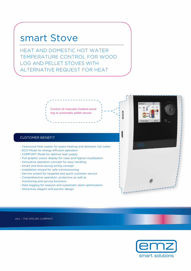
- Yearround heat supply for space heating and domestic hot water - ECO-Mode for energy-efficient operation - COMFORT-Mode for optimal heat supply - Full graphic colour display for clear and logical visualization - Innovative operation concept for easy handling - Smart and time-saving wiring concept - Installation wizard for safe commissioning - Service wizard for targeted and quick customer service - Comprehensive operation, protective as well as monitoring and service functions - Data logging for analysis and systematic plant optimization - Attractive, elegant and puristic design
CUSTOMER BENEFIT
Control of manually fuelled wood log or automatic pellet stoves
HEAT AND DOMESTIC HOT WATER TEMPERATURE CONTROL FOR WOOD LOG AND PELLET STOVES WITH ALTERNATIVE REQUEST FOR HEAT
smart Stove

smart Stove - equipment level
Hardware
Number inputs for temperature sensors PT1000 6
Number triac outputs, max. 1A - for pumps, valves 2
Number relay outputs - change-over contact, pot.-free, max. 1A - for pumps, valves, additional heating 1
Number fixed analog outputs 0…10V or PWM outputs for high-efficiency pumps 2
SD card slot for data logging, upload of hydraulic systems incl. settings, software update √
USB port for acces to SD card √
Acoustic alarm (to be deactivated) in case of messages √
Power reserve for real-time clock (min. 8 h) √
Transformer power supply, 230VAC +/-10%, 50Hz √
Full graphic TFT colour display with backlight, dimmable √
System
Multi-piece plastic housing √
Operation via rotary encoder and ESC button √
Micro fuse incl. spare fuse, type 5x20mm, time-lag 2A
Wall mounting √
Protection class IP20 √
Ambient temperature 0 … 40°C √
Active display area, width x height in mm 47 x 35
Mesaurements, width x height x depth in mm 115 x 173 x 46
Maximum number national languages 5
Number hydraulic systems (with animation of pumps, valves, aditional heating) 7
Installation wizard (selection hydraulic system, upload from SD card) √
Service wizard √
Protective functions
Over temperature protection √
Over temperature shut-off √
Antifreeze protection √
Anti-blocking protection √
Operation and efficiency functions
Flow temperature control für heating circuit (fixed set-point) √
Domestic hot water temperature control √
COMFORT-Mode for heating flow (increased set-point) √
ECO-Mode for heating flow (reduced set-point, dynamic delay of additional heating) √
COMFORT-Mode for domestic hot water (increased set-point) √
ECO-Mode for domestic hot water (reduced set-point, dynamic delay of additional heating) √
Thermostat or window function √
Automatic summer/winter time changeover √
Anti-legionella function (in conjunction with additional heating) √
Additional heat via different heat sources (selectable) √
Overtravel time for outputs √
Inversion of valve signal via menue setting √
Loading pump, speed variable, invertible √
Dynamic pump start (depending on combustion performance at wood log stoves) √
Thermostatic flame detection √
Alternative sensor selection for integrated immersion heater (depending on fitting position) √
Recommendation to light/reheat a wood log stove (to be displayed) √
smart Stove EQUIPMENT LEVEL

smart Stove - equipment level
Monitoring and Service functions
Sensor monitoring √
Monitoring the output parameters √
Remote access by USB in connection with the optional smart Box √
Sensor balancing √
Automatic sensor switching in case of sensor defect √
Service hour counter for outputs √
Data logging on SD card, upload hydraulic systems √
Display of temperatures and actuators √
Message list with messages and warnings √
Manual Mode √
Reset of complete or parameter related factory settings √
Optional accessory and customized adaptions on request
Assembly/operating instructions on CD, safety instructions as a leaflet √
Assembly/operating instructions incl. safety instructions as a booklet √
Quick Start Guide as a leaflet √
Stove sensor PT1000, grey Silicon, operation temperature range -40 … +180°C, length 2.500mm, with ferrules
√
Tank sensor PT1000, black PVC, operation temperature range -5 … +90°C, length 2.500mm, with ferrules
√
Power cable, black 230V, 3poles, H05VV-F 3G0,75mm, length 1.500mm, with ferrules
√
SD card √
OEM personalization √
Also available as a set: incl. 1 pc oven sensor PT1000 Silicon, 3 pc tank sensor PT1000 PVC, assembly/operating instructions on CD, Quick Start Guide and safety instructions as a leaflet
√

emz-Hanauer GmbH & Co. KGaASiemensstraße 1D-92507 Nabburg
Telefon: +49 (0) 9433 898-0Fax: +49 (0) 9433 898-188
OPERATION AND VISUALIZATION
- Full graphic TFT colour display with backlight - Rotary encoder with Push, ESC button - Different operation levels for OEM, heating in-staller and end user - Self-explanatory menu and user guidance - Combination of plain text displays and symbols - Different national languages
WIRING
- Easily removable terminal cover for access to the terminal compartment - Generously dimensioned terminal compartment - System-dependent wiring - Proven spring-type terminals - Convenient, intersection-free wiring - Strain relief device
Installation and Service Wizard
- Developed in common with Regensburg University and heating trade - Solar thermal plant is ready to operate with just a few settings - Selection of hydraulic systems and function blocks - Optical and/or acustical indications of malfunctions and errors - Possibility of a preliminary diagnosis by the enduser in case of error messages - Recommendations for the installer to eliminate malfunction or to perform maintenance work
Plant Visualization
- Indication of measured values for inputs and outputs - Service hour counter for outputs - Message list with messages and warnings
DATA INTERFACES
- Data interfaces such as SD card for data logging and upload of hydraulic systems or USB for soft-ware updates and remote control
smart Stove HYDRAULIC SYSTEMS
Ver
sio
n: E
N 0
8/2
015