DIFFERENTIAL RECTIFICATION OF DIGITAL OR … · After a short introduction to the problem, firstly...
10
14. CONGRESS OF THE INTERNATIONAL SOCIETY FOR PHOTOGRAMMETRY HAMBURG 1980 COMMISSION III, WORKING GROUP 1 INVITED PAPER RAINER HOSSLER LEHRSTUHL FOR PHOTOGRAMMETRIE TECHNISCHE MONCHEN ARCISSTR. 21 POSTFACH 202420 0-8000 MONCHEN 2 DIFFERENTIAL RECTIFICATION OF DIGITAL OR DIGITIZED IMAGERIES ABSTRACT After a short introduction to the problem, firstly the direct and the indirect method for differential rectification of di - gital or digitized imageries are described. Ensuing the appli- cation of these two methods to the rectification of digital satellite images, digital aircraft images and to digitized two dimensional images is discussed with regards to various aspects connected with the problem . Some aspects are : restitution of the exterior orientation, implementation of digital height mo - dels, post - processing of the output image. The last chapter deals with data handling problems . 294.
Transcript of DIFFERENTIAL RECTIFICATION OF DIGITAL OR … · After a short introduction to the problem, firstly...

14. CONGRESS OF THE INTERNATIONAL SOCIETY FOR PHOTOGRAMMETRY HAMBURG 1980
COMMISSION III, WORKING GROUP 1 INVITED PAPER
RAINER HOSSLER LEHRSTUHL FOR PHOTOGRAMMETRIE
TECHNISCHE UNIVERSIT~T MONCHEN ARCISSTR. 21
POSTFACH 202420 0-8000 MONCHEN 2
DIFFERENTIAL RECTIFICATION OF DIGITAL OR DIGITIZED IMAGERIES
ABSTRACT
After a short introduction to the problem, firstly the direct and the indirect method for differential rectification of di gital or digitized imageries are described. Ensuing the application of these two methods to the rectification of digital satellite images, digital aircraft images and to digitized two dimensional images is discussed with regards to various aspects connected with the problem . Some aspects are : restitution of the exterior orientation, implementation of digital height mo dels, post - processing of the output image. The last chapter deals with data handling problems .
294.
I ,'i T R 0 D lJ C T I C :!
~lith the beainninrJ of soace travel the C:eve~onr"'ent of diaital image recording, transmission and processing was pushed essentiallv. :laturallv firstlv devic~s for cinital ir:Ja'le recording· the so calied scanners and devices for writin-? digital imaaes were d~velooed . Soon the last ones ~e re used to diaitize ordinary nerial or other nh.ctoqraoh.v in order to apply the oossibilities of dicital i~a~e ~rocessina to the~ too. The develop~ent of the scanner went on fror"' ~hose with rotatina mirror O!'Jtics to the so called linear solid state scanners. In these scanners t~e scanninG line is sa~oled in small, discrete adjacent sensor ele~ents. It allows scanninq without any moving parts. The develoDment tendencies aine to two dimensional arravs, but the current state of technoloay a l 1 o w s o n l '/ t o p r o d u c e s r; a l 1 a r e a s o f h i a h r e s o 1 u t i o n . U :J t o now ~atric~s of 380 by 438 detectors are available (/1/).
Tf-Je techniaues and met'lods in di'Jital irr:arJe orocessillG ha·:'= been oushed to h.iah standards too. T~is is true ill regard to ~ardware as~ects as well as in reaard to software ~evelooe~ents . But f0r a lona tiTe it was not oave~ attention enounh to the first steo of-image processing , the aeome~ric r~ctification. 1nl~ since the other i~aae orocessinn rethods ~eet 'lir:Jh standards, the necessity f'"lr hich efficent ciffere!ltial rectification methods becar:e evident in ']eneral. The r~ctification itself is performed in tv1o steos. :n the first steo t~e transfor~ation oaraneters ~etween ima1e and ~errain coordinates have to be calculated and in the second steo the rectification has to be oerf0r~ed accordin1 to these oarameters. Firstl~ the transforr:a t ion ~ara~eters ~etween the distorted i~age and the ground control have to be determined. 7here are existin1 different methods, which can be divided in t~o orouos (/2/, /3!). The ~ost si~ole methods determine one set of transformation oarameters far the whole imaae accordir1 to a certain interoolaticn rTJodel (similarity transforna-t:ions, affin transformations, etc.) from available control at control aoints (/1/ , /51) . This kind o-~=" ;nethods can be sufficient for r e 1 a t i v e i :; u n d i s torte d i r: a CJ e s ( e . 7 . : s a t e l 1 i t e i m a (} e r '' ) . In qeneral thev are called non oarametric ret~ods . In ODT)OSi t e to therTJ are the parametric ~ethods . which rectificate the image data by ri?orous relations between imaae and terrain coordinates (collinearity equations). T~e variation of the un known exterior orientation oarametors from line to line is described by certain mathematical models (e . ~ . : polvnomials. G a us s '~ arc o v tJ roc e s s e s ) . Us u a l 1 y t r: e '1 e c ~ s s a r v i n :::> u t i n f o r rr a -tion are control point coordinates . T1ese rectification ~eth ods are able to consider recorde~ exterinr oiientation pa rameters, jut in ~eneral thev do not ~ecause of the low ac C:.Jracy level of the recordings . T:1at snall be en oug h for t1is tooic . It will be treated in de t ail in anot1er naner of ',1 r; I I I / 1 ( ! 6 I ) .
This pacer dea ls wit1 the second s~en of di~it al rectification the transfer of every sintlle oicture el<:>fTlent (oixel) fror;; its
295.

actual oositio n to the corrected location . For this t ask there are existing only two methods, the direct and the indirect method .
REC TIFICATION METHODS
Both methods are usinq as innut information the di gital or di gitized image, which means a rectangular matrix of~ x n nun bers renresen t ing the e1re_v shades '~ij (xi , y . ) (i = 1 ... m, j = 1 ... n) of the nicture elements . Row a~d colu~n number define the location of each pixel within the i~age.
The direct method calculates for each pixel of t~e rec t angular matrix an cutout oosition in a rectangular coordinate system . The 0rid structure however will be destroyed in the output i~aqe . The indirect method 00es the reverse way . For each oixel of a rectangular cutout grid this method calculates the corresoondino input position for the transfer of grey shades .
. . . . . . . . . . . . . . . . . . . . . . y ...... y .
Lhx ~X Direct "1ethod
comoutation of cutout oosition
·. . . . . . ..... . . . . . ...... . . . . ...... . . .......
'j y
LS, ~X Indirect ~· 1 ethod
comoutation of the corresoondin o innut pi xel to a !JlVen output oixel
RECTIFICATIO N OF DIGI TAL SATELLITE I MAGES
Digital images recorded f r om satellites are characteri z ed by a re l atively good geometric quality, which is caused by the quiet and stable fl i ght behaviour of satellites . Th i s means that also simple or less ri oorous rectification l"le t ~ods (non ~arametric m~ t hods) may suooly with qo od rectifie d i~aoery . Usinq f or examole a tw o dimensional oolvno~ial of s e cond or der ·.~ e ge t t he f o 1 1 ow i n g form u l as f or t he d i r e c t ( 1 ) and the indirect (2) recti f ica ti on me t ~od .
296.

0 i re c t met~od :
X = ao
y = b 0
Indirect
X = c 0
d y = 0
+ a 1x + a zY + a 3xy + a4x 2
+ b1x + b2y + b3xy + b11 x 2
method:
+
+
c1x + c 2Y + c3XY + c4X 2
d1
X d2Y ct 3XY 2 + + + d 1 X '+
X,Y: terrain coordinates
x,y: image coordinates
+
+
+
+
asy 2
b5y 2
y2 c5 ,
d y2 5
( 1 a )
( 1 b )
( 2 a )
( 2 b )
The parameters a, b or c, d have to be determined by a least squares adjustment. The necessary observation equations can b e d e r i v e d f r o m e q u a t i o n ( 1 ) r e s o . ( 2 ) , 'tl h i c h 1 e a d t o t w o e -quations for each control ooint. The disadvantage of the direct method is, that it does not result in a reaular nutout grid. Aoart from the non regular grid, which wifl be obtained, the outout image has gaps and overlaos . T~at means that from this i~aoe a reoular arid must be comouted for the diaital image outp,ut device . This has to be done off-line using the methods Gf digital image processing . In contrast to it the indirect method has the bia advantaoe that a reqularlv formed outnut grid will be obtained immedi~tely. - -
However, the more efficient the sensors become (which firstlv means hi~her resolution) the better the rectification methods (parametric methods) have to be . Especiallv relief disnlacement has to be taken into consideration. For images taken from aircraft this is absolutely necessary, if good rectification results shall be obtained.
RECTIFICATION OF DIGITAL AIRCRAFT I '1AGES
Digital aircraft imaaes are characterized by relatively large distortions and biq relief di splacements caused by wide scan angles , if the sur*ace has not been too flat . For . the rectification of aircraft scanner images therefore hioh efficient methods (~arametric methods) using rigorous formulas dessrib ing the relation between image and ground coordinates have to be aoplied . The collinearity equations are those rigorous relations between image and terrain. Certain inaccuracies caused by the exterior orientation parameters are u~avoidable, because it is not possible to determine them for each imane line ( recordings are to inaccurate up to now). The v~riations from line to line have to be modeled adequately in or der to bridoe over controlless areas . Thus the various methods differ from - each other . Such methods can use oolvnomials, Gauss Marcov orocesses (random orocesses), Fourier Functions
297.

or something else. Apart from that unavoidable inaccuracy the following equations are the rigorous relations between image and terrain.
Direct rr.ethod:
alljx + al2jy - al3jc X = ( z - z . ) + :<
OJ a3ljx + a32jy - a33jc
oj ( 3 a )
( 3 b )
Z = f(x,y) fron a di'Jital '1ei~ht model ( J ~ ~.1 \ ' I
Indirect method:
x = -c rx -. ) ('~ v ) (~ z ' a,,.~· - ·" ;.+a?li , - , .,+al1iL- · ;
- - J 0 v - J () J ~ - .J ____ tU__
a 13 ~(X-X .)+a?J .(Y -Y .)+a~ 3 ;(Z-Z ;) J 0.) - J OJ J ._, OJ
a 1 ?;(X-X ;)+a?";(Y-Y .)+a 12 .(z-zn .) y = - c ~ ~ ,/ 0 .) '- {_ .j c J ~ ,J ~- f 1 '- I
' -"_I
a,3,(X-X .. )+a?~.(Y-Y .)+a..,.,.(Z - Z .) - 1' o~· -JJ' 'J~ 5v1 O]'
Z = f(X,Y) f'rorn a JH ' 1
Wi th
c: calibratec -Focal lenat~:
aikj = f (wj, ¢j' Kj) =l. .. J , <=l .. . 3
j: index of the i~ase line
The exterior orientation oarameters X0 ;, Y0
; . Z0 ;. w;, t ;, Ki mav be functions of the ima~e coordinates x~ v a~ us~d f6r · in~tance for polynomials (I~!) . o more adeaua~e wav to model the time deoendend courses of t~e exterior orientation oar~ ~eters can be the use of stochastic (random) orocrsses cs it i s s h o 1v n e . r:J • i n I ~ / a n d I 9 I .
3oth methods (direct , indir-ect) need f0r .;: co""olete rectifi c a t i o n h e i rJ h t i n f o r rn a t i o n . T ~ e d i r e c t ~ e t '1 o d n e e ,: s 2 J ~ ' ! based on imarJe coordinates . Sut usually the '.Y ' 1 's exist in rectangular 0rids based on oround coorcinates . The r e f 0re t~e height must be calculated by intersecting t~e orojection beam with the surface of the 8~ ~. This sur f ace ~as to ~e rode l ed artificially by usina the surroundina discrete '1eiaht infer -
298.
!'lation of several nrid points . 11sually t~e internolation between the discrete ~ein~ts aoes li~early i1 X and Y if the srid is dense enouoh. Th~ intersec:ion has to be calculated iteratively. The nu~ber of iterations strqnalv deo2nrls on t~e ~round for~ and on the aonroxi~ate value Z of the heicht which has to be c~lculated . It is easv to obtain nood aJproximate values'""· If firstl 't the nround co0rdinates o~ t'le fir~t and the last 8ixel of each line are deter~ine~ hv i1-tersect~n~ the n~ojection ~eams wit~ the ~H~, the ~ooroxi~ate values X, ? and Z of t ~ e oth2r Jict ure ele~ents can b e c3lcu lated very easily fro~ t~e known oixel size an~ the k1awn ~eneral direction of t he 1rojecte 1 l ine on ~h~ ~ round ( t ~ e o r o j e c t i o n i s n o t a s t r a i a ~ t l i n e ) . ~ .' s u a l 1 ~' o n e i t e r 3 t i o n o ~ the intersection will ~e enounj, Jecaus? t~e deviations of t h e n e 1·1 v a l u e s :< , Y , Z fro rn ? , ·r , Z 'II i l l be '" i t 1 i n a. c c e o t a b l e tolerances . Connected 'Hith this tooic is t~e !:!rrJC:·l~rn of hid den surfaces and multiole solutiCJns . ,:1. ':le f i~it solution f'l ay be fcund as exllained for instance in / ! "/. Su bseauent1v ~~e outnut i~aae has to be processed bv ~ea~s c ~ diaital i~a~e
Jrocessin~ too, because of the qa1s an~ o v~r l 3~S.
The indirect ~av needs the ~ei~ht informati on ~ased on a rect an 'J u l a r 'J r 0 u n d c o o r d i '1 a t 2 !1 r i ~ . '.; s u a l 1 ~ ~ 2 ~~ ~ ~ I r; d o 1 ::l v e t ~ i s c o n f i tJ u r a t i o n , e v e n t u a l 1 ~~ t h e y h a v e t o :: ~ ~~ e !l s i -F i ~ ~~ . r- r a i'1
J r. f1 1 s b as e d on t r i 3 n a 1 e '1 e s "'e s , the r e c t an 'l u l :; r n r i j 1 as t J
b e i n t e r 'J 0 1 a t e d f i r s t l .:1 .
When calculatin0 the ~osition x, y of a Jixel i n t~e i~aae snace the oroble~ aooears, tha t ~e do not k ~cw, ~ ~ich oroiection center (we ~ave one far eac1 line) belonos to the around pixel. A solution ~or this oro b len can be foun d bv calculating the correct projection center iteratively, if the orientation parameters depend on x and y (/ 11 / ) . If they do not (/ 9/ ) the solution can be very complicated . In this case the direct method shouid be preferred .
R EC:TIFIC.~TIOri OF CISITIZED T'.!O DI'~E ~lSIO ~LL1L I ' ~!'IGES
Jir:;lital i;naoe orocessing and digitc.l rectification resoectivelv most l v have been used for remote sensina aoplications, but can be aoolied to conventional i~agerv too~ if they have been dicitized before. For aerial ohoto~raohv then we have t h e v1 e l i k n o 'tJ n c o 1 l i n e a r i t y e o u a t i o n s , ;, h i c h - a i v e u s t h e r e -lation between ground and image coordinates.
a1 , (X - X ) + azl(Y - Yo) + a3l(Z - Zo) .L 0
X = - c ( 5 a ) a13(X - Xo) + az3(Y - Yo) + a33(Z - Zo )
( v 'I ) + azz(Y - Yo) + ( 7 7 ' 3 1 ? '- ,, . aJz , ~-Lo ' ~ 0 y = -c ( c:: h \
- u I
I '< '( \ al 3' -. o 1 + a 2 3 (Y - Y0
) + a33(Z - Zo)
Z = f(:<, Y) f rom a J H'1
299.

The set of the six orientation parameters X0 , Y0 , Z0
and w, ~. K (aik = f (w, cb,K)) can ~e calculated for instance bv are section in space. Because we do have a two dimensionalJ image with only one corresponding projection center we do not have coordination problems as exolained above. Therefore we can applv both methods (direct, indirect) without di ffi cul ties . In this case the indirect method (formulas (Sa), (Sb)) should be preferred, because then we can avoid to calculate a rectangular outout grid afterwards. The height information must be based on a rectangular ground coordinate grid. Existing OHM's eventually have to be densified or interpolated aaain if they do not have rectangular meshes . -
There are interestina aoolications in terrestrial ohotonram metry too, esoeciall~ i~ · the field of architecture phot~ grammetry, where often unwindable facades have to be reeled off onto a olane , which can be done very comfortable by digital imaae processing methods as exolained in /12/. For this task an analytical formulation of the object to be rectified is necessary in advance (the corresponding task in aerial ohotoqraohy would be the implementation of a DHM). Thus we are able to calculate rectified object coordinates of each picture element and its position in the projection . In this case the indirect method has the same advantaaes as exolained above for aerial ohotoqraohy and can be used very successfully for digital rectification.
DATA HANDLI~G ASPECTS
Data handling is the biqgest oroblem of digital differential rectification. Secause of the very large auantity of data, which has to be processed, an ootimal data handling conceot vlill hela to save time and costs. Operational orograms should find a reasonable middle coarse between storage and comouting time requirements. Roughly said time and storage are reciprocal to each other. As storage in core usually is a limiting factor the rectification has to be done in blocks .
Cons .~ering the direct rectification method using col linearity equations, we are able to estimate the extent of an output matrix, which is necessary in order to rectify one single image line on-line by directly addressing in core. The extent of the matrix we get from simplified differential equations (6). They are true for a central perspective linear array scanner .
= - hll¢ e
- h tan -z llK ( 5 a)
~Y = tan~ ~Z 0 + h(1+tan 2 ~)~w (6b) max c.. c..
The scanner characteristics are assu~ed to be: resolution 13 ~m , c = 24 mm, scan angle e = soo and 1728 pic-
300.
ture elements oer image line . This corresponds with the elec tro opt~ca~ (1 inear array) scanner of ,,l BP (corr:pare /1 41) . The dev1at1ons of the orientation parameters are assumed to be within the following values (comoare /13/) :
6Z0
< 0 . 02h, 0 6w < 5 ,
In the worst case , if all the deviations have the same sinn, we qet , exoressed i n Pixels of ground resolu t ion:
ljx I max "' 300 [ r s u]
JD. Y I max "' 21JO (rsuJ
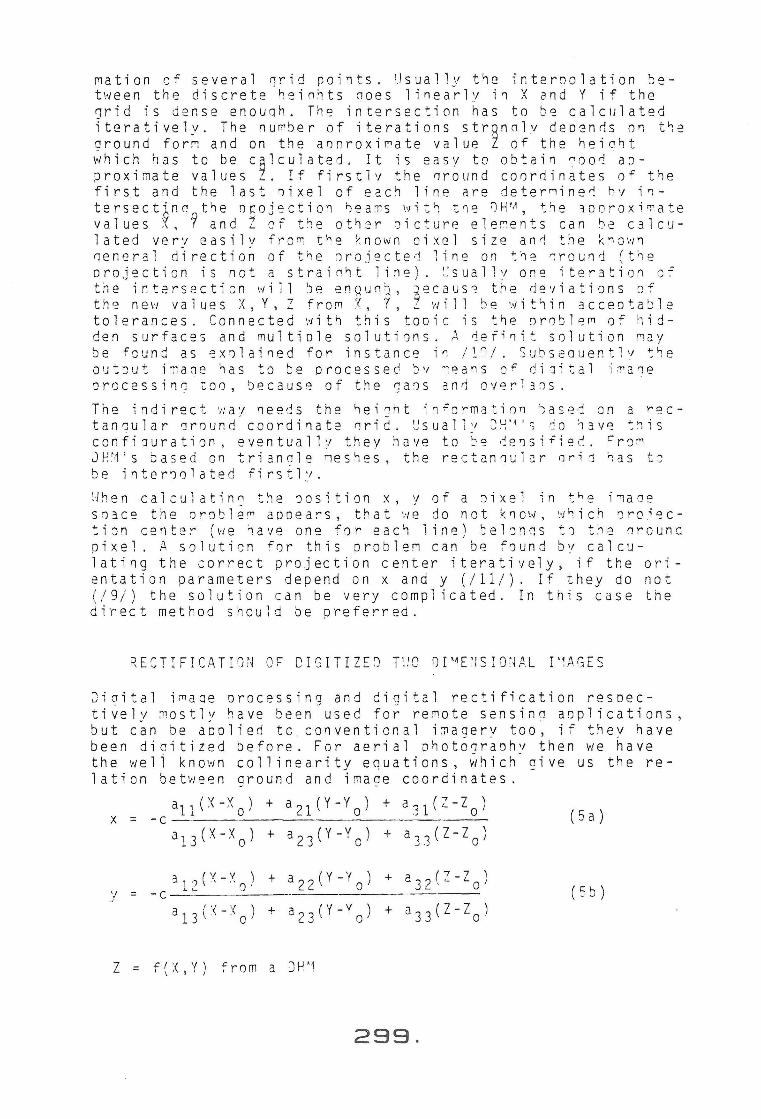
Therefore we should have an outcut matrix of not less than 600 x 2122 elements, if we would l ik e to address the cutout pixels directly in central memory .
I I I I I I I I I I I I I I I I I I I I I 500 172 8
21 2 8
Input Image line Outout Imane Matrix
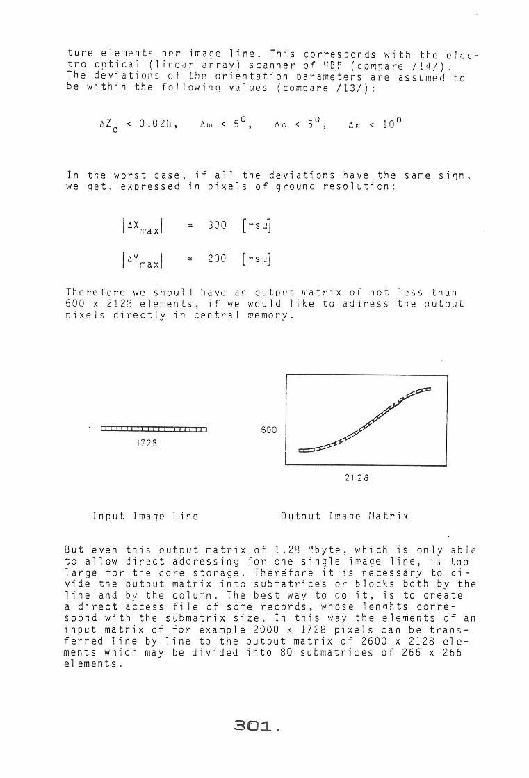
But even this outcut matrix o f 1 . 2S ~ byte, which is only able to allow direct addressing for one single image line , is too large for the core storage . Ther~fore it is necessary to di vide the cutout matrix into submatrices or blocks both by the line and by the column . The best way t o do it , is to create a direct access file of some records , whose lennhts corre spond with the submatrix size . In this way the elements of an input matrix of for example 2000 x 1728 pixels can be trans ferred line by line to the output matrix of 2600 x 2128 ele ments which may be divided into 80 submatrices of 266 x 266 elements .
30:1..

2000
1728
Input Matrix (actual reauired storage: 1 line)
I 266 I
266 -+-I
-+-I I I
~-+-+-+-I I I 2600
2128
Outout Matrix (actual required storaqe: submatrix of 265 x 266 elements)
This direct access technique has the big advantage, that the central memorv demand, which is the main limiting factor of a comouter, can be lowed down to the absolute Minimum if the submatrix size is made very small . Therefore such digital rectifications even can be done on minicomouters, which usu ally have a core memorv caoacity from 32 K-bytes, uo to 256 K-bytes and direct addressable disk cartridges of several M- bytes. By it comouting times will rise, but that is no lim iti ng fact or, because minicomputers usually belong tn a small circle, which does not employ the comouter to ,capac ity .
Equal considerat1ons are true for the indirect rectification method with chanaed signs . In this case the outout image is handled sequentially line by line and the input image has to be stored divided in submatrices and direct accessible .
Comouting times can be lowed down essentially, if only some pixels are transferred using collinearity equations and digi tal height information. To the oicture elements located with in those corner points simple rectification ~ethods (e.g . interpolation models) can be apnlied to . But reducing com puting times by this way could be payed by a certa i n loss of accuracy .
An i nteresting possibility for di gital differential rectifi cation of aerial photography in connection with a microden sitometer was shown in / 15/ . Us i ng the indirect rectification method for each pixel of the output matrix the corresponding input position is calculated using the rigorous equations and height information from a OHM . Then the densitometer is moved by servomotors into this position in order to take the grey shade of the pixel . The grey shades a r e stored on a magnetic tape . This method can be done with a re l atively small comput er, because there are only low demands on storage caoacity .
302.
REFERENCES
/1/ MONTUORI, J.S.: Image Scanner Technology. Photogrammetric Engineering and Remote Sensing, pp. 49-61, 1980
/2/ KONECNY, G.: Mathematical Models and Procedures for the Geometric Restitution of Remote Sensing Imagery. Invited paper, XIII. Congress of the I_nternational Society for Photogrammetry, Helsinki, 1976
/3/ BAKER, J.R. and Mikhail, E.M.: Geometric Analysis and Restitution of Digital Multispectral Scanner Data Arrays. LARS Information Note 052875, Purdue University, West Lafayette, USA
/4/ GOPFERT, W.M.: High-Precision Scanner Imagery Rectification Using Dynamic Meshes of Digitally Correlated Pass Points. Presented paper, International Symposium on Image Processing - Interactions with Photogrammetry and · Remote Sensing, Graz, 1977
/5/ WIESEL, J.: Auswertungen fUr das Flugzeugmessprogramm mit dem digitalen Bildverarbeitungssystem DIDAK. Symposium Flugzeugmessprogramm, Hannover, 1977. BMFT FBW 78-04, pp. 389-394, 1978
/6/ MIKHAIL, E.M.: Current Status of Metric Reduction of (Passive) Scanner Data. Paper to be presented, XIV Congress of the International Society for Photogrammetry, Hamburg, 1980
/7/ KONECNY, G.: Methods and Possibilities for Digital Differential Rectification . Photogrammetric Engineering and Remote Sensing, pp. 727-734, 1979
/8/ HOSSLER, R.: High Accurate Geometric Rectification -Necessity and Realization. Presented paper, ISP Commission VII Symposium, Freiburg, 1978
/9/ EBNER, H. and HOSSLER, R. : The Use of Gauss-MarcovProcesses ' in Diqital Rectification of Remote Sensing Data. Presented-paper, ISP Commission III Symoosium, Moscow, 1978
/10/ UNRUH, J., AlSPANGH, D. and MIKHAIL, E.M.: Sensor Simulation from Spectral and Digital Terrain Data. Information Note 47907, Purdue University, 1977
/11/ SCHUHR, W.: Digitale Entzerrung multisp~ktraler Bilder. BuL, pp. 202-208, 1976
/12/ B~HR, H.-P.: Digital Rectification of a Facade. Presented paoer, ISP Commission III Symposium, Moscow, 1978
/13/ KONECNY, G.: Development and Possibilities of Digital Image Correlation and Digital Differential Rectification. Presented oaper, ISP Commission II Symposium, Paris, 1978
/14/ HOFMANN, 0. and SEIGE, P .: Erste Erprobungsergebnisse mit der experimentellen optoelektronischen Kamera von MBB. BuL, pp. 33-40, 1979
/15/ KEATING, T.J. and BOSTON, D.R.: Digital Orthophoto Production Using Scanning Microdensitometers. Presented paper, ISP Commission III Symposium, Moscow, 1978
303.