DIFFERENTIAL PRESSURE (FLOW) TRANSMITTER · The transmitter can be configured to provide a constant...
10
DIFFERENTIAL PRESSURE (FLOW) TRANSMITTER Remark : To minimize environmental influence, span should be greater than 1/40 of the max. span in most applications. Important : For FKC#49, max possible overload pressure on LP side must be ≤ 100 bar. The accuracy is not guaranteed when used at negative DP FKC 11 FKC 22 FKC 33 FKC 35 FKC 36 FKC 38 FKC 43 FKC 45 FKC 46 FKC 48 FKC 49* -0.1 to +3.2 {-1 to +32} -0.1 to +10 {-1 to +100} -0.1 to +16 {-1 to +160} -0.1 to +16 {-1 to +160} -0.1 to + 16 {-1 to +160} -0.1 to +16 {-1 to +160} -0.1 to +42 {-1 to +420} -0.1 to +42 {-1 to +420} -0.1 to +42 {-1 to +420} -0.1 to +30 {-1 to +300} -0.1 to +30 {-1 to +300} ±1 {±10} ±6 {±60} ±32 {±320} ±130 {±1300} ±500 {±5000} ±3000 {±30000} ±32 {±320} ±130 {±1300} ±500 {±5000} ±3000 {±30000} +20000,-10000 {+200000,-100000} 0.1 {1} 0.1 {1} 0.32 {3.2} 1.3 {13} 5 {50} 30 {300} 0.32 {3.2} 1.3 {13} 5 {50} 30 {300} 500 {5000} 1 {10} 6 {60} 32 {320} 130 {1300} 500 {5000} 3000 {30000} 32 {320} 130 {1300} 500 {5000} 3000 {30000} 20000 {200000} Min. Model Range limits kPa {m bar} Static pressure MPa {bar} Span limits kPa {m bar} Max. SPECIFICATIONS Functional specifications Type : FKC : Smart, 4-20mA + HART/Fuji Electric communi- cation protocols. Service : Liquid, gas, or vapour Static pressure, span, and range limits : Lower limit of static pressure (vacuum limit) : Silicone filling oil : See Fig. 1 Fluorinated filling oil : 66 kPa abs (500 mmHg abs) at tem- perature below 60°C Over range limit : To maximum static pressure limit DATA SHEET EDSF6-134m July, 2018 Date Fuji Electric France S.A.S. The FKC model of the FCX-AII V5 series of pressure transmit- ters accurately measures differential pressure, liquid level or flow rate and transmits a proportional 4-20 mA output signal. The transmitter uses an unique micro-capacitive silicon sensor in combination with a state-of-the-art digital signal processing to provide exceptional performances in terms of accuracy and stability. FEATURES 1. High accuracy up to ±0.04% Fuji Electric’s micro-capacitive silicon sensor provides in standard ±0,065% accuracy for all elevated or suppressed calibration ranges without additional adjustments. ±0.04% accuracy is available in option. 2. Minimum inventory and design Electronics unit, local indicators and electronics housing are interchangeable among all FCX-AII V5 transmitters. 3. Minimum environmental influence The Advanced Floating Cell technology provides a high im- munity against temperature variations, static pressure and overpressure commonly found in the process industry and substantially reduces the overall measurement error. 4. HART/Fuji Electric communication protocols FCX-AII V5 series of pressure transmitters can communicate using either the universal HART or the proprietary and faster Fuji Electric communication protocol. By the use of Device Description files, HART compatible devices can communicate with any FCX-AII V5 transmitter. 5. Application flexibility Various options are available to address most of the process industry applications, including : - Full range of hazardous area approvals - Built-in RFI filter and lightning arrester - Analog or 5 digits local display with engineering units - Stainless steel electronics housing - Wide selection of wetted part materials 6. Programmable output Linearization Function The output signal can be linearized using up to 14 pair- points. 7. Burnout current flexibility The burnout current value can be adjusted in the ranges of [3.2 ; 4.0] and [20.0 ; 22.5] mA and can be compliant with NAMUR NE43 recommandations. FKC ... 5
Transcript of DIFFERENTIAL PRESSURE (FLOW) TRANSMITTER · The transmitter can be configured to provide a constant...

DIFFERENTIAL PRESSURE (FLOW) TRANSMITTER
Remark : To minimize environmental influence, span should be greater than 1/40 of the max. span in most applications.
Important : For FKC#49, max possible overload pressure on LP side must be ≤ 100 bar. The accuracy is not guaranteed when used at negative DP
FKC 11
FKC 22
FKC 33
FKC 35
FKC 36
FKC 38
FKC 43
FKC 45
FKC 46
FKC 48
FKC 49*
-0.1 to +3.2{-1 to +32}
-0.1 to +10{-1 to +100}
-0.1 to +16{-1 to +160}
-0.1 to +16{-1 to +160}
-0.1 to + 16{-1 to +160}
-0.1 to +16{-1 to +160}
-0.1 to +42{-1 to +420}
-0.1 to +42{-1 to +420}
-0.1 to +42{-1 to +420}
-0.1 to +30{-1 to +300}
-0.1 to +30{-1 to +300}
±1{±10}
±6{±60}
±32{±320}
±130{±1300}
±500{±5000}
±3000{±30000}
±32{±320}
±130{±1300}
±500{±5000}
±3000{±30000}
+20000,-10000{+200000,-100000}
0.1{1}
0.1{1}
0.32{3.2}
1.3{13}
5{50}
30{300}
0.32{3.2}
1.3{13}
5{50}
30{300}
500{5000}
1{10}
6{60}
32{320}
130{1300}
500{5000}
3000{30000}
32{320}
130{1300}
500{5000}
3000{30000}
20000{200000}
Min.Model
Range limitskPa {m bar}
Static pressureMPa {bar}
Span limits kPa{m bar}
Max.
SPECIFICATIONSFunctional specifications
Type : FKC : Smart, 4-20mA + HART/Fuji Electric communi-
cation protocols.Service : Liquid, gas, or vapourStatic pressure, span, and range limits :
Lower limit of static pressure (vacuum limit) :Silicone filling oil : See Fig. 1Fluorinated filling oil : 66 kPa abs (500 mmHg abs) at tem-perature below 60°C
Over range limit : To maximum static pressure limit
DATA SHEET
EDSF6-134mJuly, 2018DateFuji Electric France S.A.S.
The FKC model of the FCX-AII V5 series of pressure transmit-ters accurately measures differential pressure, liquid level or flow rate and transmits a proportional 4-20 mA output signal. The transmitter uses an unique micro-capacitive silicon sensor in combination with a state-of-the-art digital signal processing to provide exceptional performances in terms of accuracy and stability.
FEATURES1. High accuracy up to ±0.04% Fuji Electric’s micro-capacitive silicon sensor provides in
standard ±0,065% accuracy for all elevated or suppressed calibration ranges without additional adjustments.
±0.04% accuracy is available in option.2. Minimum inventory and design Electronics unit, local indicators and electronics housing are
interchangeable among all FCX-AII V5 transmitters.3. Minimum environmental influence The Advanced Floating Cell technology provides a high im-
munity against temperature variations, static pressure and overpressure commonly found in the process industry and substantially reduces the overall measurement error.
4. HART/Fuji Electric communication protocols FCX-AII V5 series of pressure transmitters can communicate
using either the universal HART or the proprietary and faster Fuji Electric communication protocol.
By the use of Device Description files, HART compatible devices can communicate with any FCX-AII V5 transmitter.
5. Application flexibility Various options are available to address most of the process
industry applications, including : - Full range of hazardous area approvals - Built-in RFI filter and lightning arrester - Analog or 5 digits local display with engineering units - Stainless steel electronics housing - Wide selection of wetted part materials6. Programmable output Linearization Function The output signal can be linearized using up to 14 pair-
points.7. Burnout current flexibility The burnout current value can be adjusted in the ranges of
[3.2 ; 4.0] and [20.0 ; 22.5] mA and can be compliant with NAMUR NE43 recommandations.
FKC...5
2
FKC...5
Configuration : Configuration of the FCX-AII V5 series of pressure transmitters
can be carried out by either using a Hand Held Communicator (ie. Fuji Electric FXW or third party HART terminal) or the 3 push-buttons optional indicator.
A third party HART hand held communicator can be used in combination with Fuji Electric FCX-AII V5 HART Device Description files (https://fieldcommgroup.org).Functions Fuji Electric
FXWThird party HART HHC
3 push buttons optional indicator
Display Set Display Set Display Set
Tag Nb v v v v v vModel Nb v v v v v vSerial Nb & Software revision v — v — v —
Engineering units v v v v v vUpper Range Value v — v — v —Measuring Range v v v v v vDamping v v v v v v
Output sig-nal type
Linear v v v v v vSquare Root v v v v v v
Burnout current v v v v v vCalibration v v v v v vOutput Adjust — v — v — vMeasuring Value v — v — v —Self Diagnosis v — v — v —
Printer (option) v — — — — —
External Adj Screw Lock v v v v v vTransmitter Display v v v v v vLinearization — — v v v vRerange v v v v v vSaturation Current v v v v v vWrite Protect v v v v v vHistory– Calibration History– Ambient T° History
vv
v—
vv
v—
vv
v—
Note 1 : The FXW firmware revision must be higher than 7.0 in order to address FCX-AII V5 “Saturation current”, “Write protect” and “History” functions.
Note 2 : The “Linearization” function is not accessible throught the 3 puh-buttons optional indicator.
Zero and span adjustment : Zero and span are adjustable with a Hand Held Commu-
nicator or locally with the external adjustment screw.Damping : The damping time constant can be adjusted within the
range of [0.06 to 32] seconds. Zero elevation / suppression : Zero can be adjusted within the range of ±100% of the
URL of the sensor.
Output signal : 4-20 mA (linear or square root) with digital signal super-
imposed on the analog signal Power supply : 10.5 to 45 V DC at transmitter terminals. 10.5 to 32 V DC with the optional arrester. Refer to hazardous location table for specific limitations.Load limitations : see figure below
Hazardous locations :
2000
R [Ω]
1500
1000
Load
res
ista
nce
250
0
1533
600 Operatingarea
Communication range with HandHeld Communicator(HHC)
24 4510.6 16.1E [V]
Power voltage
E [V] -10.5
(I max [mA]+0.9)x10-3R [Ω] =
When the upper limit of the saturationcurrent (Imax) is 21.6 mA
Note 1 : The load resistance varies with the upper limit of the saturation current [I max]
Note 2 : For communication with HHC (FXW model), a minimum load of 250 Ω is required.
Marking (Digit 10 =) Protection typeATEX
(K)
Intrinsic Safety “i” :
Ex II 1G/DEx ia IIC T4 Ga (-40°C ≤ Ta ≤ +70°C)Ex ia IIC T5 Ga (-40°C ≤ Ta ≤ +50°C)Ex ia IIIC T135°C Da (-40°C ≤ Ta ≤ +70°C)Ex ia IIIC T100°C Da (-40°C ≤ Ta ≤ +50°C)IP 66/67Electrical Parameters :Ui ≤ 28 Vdc, Ii ≤ 94,3 mA, Pi ≤ 0,66 WCi = 26nF(1) / 36 nF(2), Li = 0.6 mH(3) / 0.7mH(4)
(X)
Flameproof Enclosure “d”:Ex II 2G/DEx d IIC T5 Gb (-40°C ≤ Ta ≤ +85°C)Ex d IIC T6 Gb (-40°C ≤ Ta ≤ +65°C)Ex tb IIIC T100°C Db (-40°C ≤ Ta ≤ +85°C)Ex tb IIIC T85°C Db (-40°C ≤ Ta ≤ +65°C)45 Vdc max
(P)
Increased Safety “e” :Ex II 3G/DEx ec IIC T5 Gc (-40°C ≤ Ta ≤ +70°C)Ex tc IIIC T100°C Dc (-40°C ≤ Ta ≤ +70°C)45 Vdc max
(M) Combination (K) + (X)IECEx
(T)
Intrinsic Safety “i”:Ex ia IIC T4 Ga (-40°C ≤ Ta ≤ +70°C)Ex ia IIC T5 Ga (-40°C ≤ Ta ≤ +50°C)Ex ia IIIC T135°C Da (-40°C ≤ Ta ≤ +70°C)Ex ia IIIC T100°C Da (-40°C ≤ Ta ≤ +50°C)IP 66/67Electrical Parameters :Ui ≤ 28 Vdc, Ii ≤ 94,3 mA, Pi ≤ 0,66 WCi = 26nF(1) / 36 nF(2), Li = 0.6 mH(3) / 0.7mH(4)
(R)
Flameproof Enclosure “d”:Ex d IIC T5 Gb (-40°C ≤ Ta ≤ +85°C)Ex d IIC T6 Gb (-40°C ≤ Ta ≤ +65°C)Ex tb IIIC T100°C Db (-40°C ≤ Ta ≤ +85°C)Ex tb IIIC T85°C Db (-40°C ≤ Ta ≤ +65°C)45 Vdc max
(Q)
Increased Safety “e” :Ex ec IIC T5 Gc (-40°C ≤ Ta ≤ +70°C)Ex tc IIIC T100°C Dc (-40°C ≤ Ta ≤ +70°C)45 Vdc max
(N) Combination (T) + (R)
cCSAus
(J)
Intrinsic safety / Non Incendive / Class 1 Division 2 :IS Class I Division 1, Groups ABCD Ex iaClass II Groups EFG; Class IIINI Class I Division 2, Groups ABCD(Per control drawing TC522873)Class I Division 2, Groups ABCDT4 (-40°C ≤ Ta ≤ +70°C)T5 (-40°C ≤ Ta ≤ +50°C)Vmax = 28 Vdc, Imax = 94.3 mA, Pmax ≤ 0.66 WCi = 26nF(1) / 36 nF(2), Li = 0.6 mH(3) / 0.7mH(4)
(E)
Explosion proofXP Class I Division 1, Groups CDClass II Groups EFG; Class IIIT5 (-40°C ≤ Ta ≤ +85°C)T6 (-40°C ≤ Ta ≤ +65°C)Vmax = 42.4 Vdc
(L) Combination (J) + (E)ATEX
IECEx
cCSAus
(W) Combination (K) + (X) + (T) + (R) + (J) + (E)
(1) Without optional arrester (3) Without analog indicator(2) With optional arrester (4) With analog indicator

3
Normal / reverse action : Selectable from a Hand Held CommunicatorLocal indicator : One optional analog or 5-digits digital indicator.Burnout direction and saturation currents : If the self-diagnostic functions detect a transmitter failure,
the burnout function will drive the output signal to either “Output Hold”, “Output Overscale” or “Output Underscale” modes.
When “Output Hold” : The output signal is held as the last value just before the failure
happens. When “Output Overscale” : The output signal is set within the range of [20.0 to 22.5] mA When “Output Underscale” : The output signal is set within the range of [3.2 to 4.0] mA Both burnout and saturation current can be adjusted within
the range of [3.2 ; 4.0] and [20.0 ; 22.5] mA
3.2 3.8
3.6 4 20
20.8 22.5
21.6 [mA]
Normal operating range
Burnout
Saturation
Burnout
Saturation
Loop-check / fixed output current : The transmitter can be configured to provide a constant
output signal from 3.2 up to 22.5 mA.Low flow cut-off : The output signal is proportional to √ differential pressure
between low flow cut-off and the measuring range. Be-tween zero and low flow cut-off, the output signal is pro-grammable to zero or linear between 0 and 20% of the flow.
Temperature limit : Ambient : -40 to +85°C -20 to +80°C (with optional LCD unit) -40 to +60°C (with optional arrester) Please refer to the hazardous locations table for ambient
temperature limitations according to the standard and type of protection.
Process : -40 to +120°C for silicone filling oil -20 to +80°C for fluorinated oil filling oil Storage : -40 to +90°CHumidity limit : 0 to 100% RH (Relative Humidity)
Performance sPecifications for linear outPutReference conditions, silicone filling oil, SS 316L isolating dia-phragms, 4 to 20 mA analog output in linear mode.Accuracy rating : (including linearity, hysteresis, and repeatability)
Max span : 32 kPa to 3000 kPa models :For spans > 1/10 of URL : ±0.065% of span or ±0.04% of span (optional)For spans < 1/10 of URL :
± (0.015 + 0.005 x ) % of span
Max span 20 MPa models :For spans ≥ 5 MPa : ±0.1% of spanFor spans < 5 MPa : ± (0.05 + 0.05 x ) % of span
URLSpan
5MPaSpan
Range code (6th digit in the model code)
“1”/1 kPa {10 mbar}“2”/6 kPa {60 mbar}
“3”/32 kPa {320 mbar}
“5”/130 kPa {1300 mbar}
“6”/500 kPa {5000 mbar}
“8”/3000 kPa {30000 mbar}
“9”/20000 kPa {200000 mbar}
URLSpan
Total effect(% of span)
Zero shift(% of span)
± (0.125+0.1 ) %
± (0.075+0.0125 ) % ± (0.095+0.0125 ) %
± (0.15+0.1 )%
Double the effects for material code (7th digit in model code) “H”, “M”, “T”
Double the effects for material code (7th digit in model code) “H”, “M”, “T”
Double the effects for material code (7th digit in model code) “H”, “M”, “T”
Max span 1 kPa and 6 kPa models :For spans greater than 1/10 of URL : ±0.1% of spanFor spans below 1/10 of URL :
± (0.05 + 0.005 x ) % of spanStability : ±0.1% of the URL for 10 years for 6th digit code 3, 5, 6, 8
and 9.Temperature effect : Effects per 28°C changewithin the range of -40°C and +85°C
URLSpan
URLSpan
URLSpan
URLSpan
Static pressure code(5th digit in the model code)
“1” / 1 kPa {10 mbar} sensor“2” / 6 kPa {60 mbar} sensor
“3”“3”“4”“4”
±0.2% / 3.2 MPa {32 bar}±0.2% / 10 MPa {100 bar}
±0.1% / 16 MPa {160 bar} FKC35,36,38±0.15% / 16 MPa {160 bar} FKC33±0.25% / 42 MPa {420 bar} FKC43,45,46,48±0.2% / 10 MPa {100 bar} FKC49
Zero shift (% of URL)
Static pressure code(5th digit in the model code)
“1” / 1 kPa {10 mbar} sensor“2” / 6 kPa {60 mbar} sensor
“3” “4”
Zero shift(% of URL)
±0.035% / 6.9 MPa {69 bar}±0.2% / 6.9 MPa {69 bar} FKC49
±0.2% / 3.2 MPa {32 bar}±0.2% / 10 MPa {100 bar}
Static pressure effect :
Overrange effect :
Performance sPecifications for square root outPut Accuracy rating :
Temperature effect : Effects per 28°C changewithin the range of -40°C
and +85°C
Max span 1kPa and 6kPa models :
± (0.24+0.03125x ) % / 28°C
Range code Shift at 20% output point
“1” and “2”
“3” through “9”
± (0.375+0.25x ) % / 28°CURLSpan
URLSpan
Output Accuracy
50 to 100%20 to 50%10 to 20%
±0.1 %±0.25%±0.5 %
50 to 100%20 to 50%10 to 20%
±0.065 % ±0.163 % ±0.325 %
Span
Output
±(0.015+0.005 × URL/Span)%±2.5 × (0.015+0.005 × URL/Span)%±5 × (0.015+0.005 × URL/Span)%
below 0.1 × URLover 0.1 × URL

4
FKC...5
Remark : Gasket : Viton o-ring or PTFE square section gasket. Availability of above material design depends on ranges and static
pressure according material codes V, H, M and T. Refer to the “Model code symbols”.Non-wetted parts material : Electronics housing : Low copper die-cast aluminum alloy finished with polyester
coating (standard), or SS 316 (option). Bolts and nuts : Cr-Mo alloy (standard). Options : SS 316 (L) for static pressure if 160 bar max. SS 660 (M10) for static pressure < 160 bar. SS 660 (M12) for static pressure > 160 bar Filling fluid : Silicone oil (standard) or fluorinated oil (option) Mounting bracket : SS 304L or 316L (option)Environmental protection : IEC IP66/IP67 and Type 4XMounting : Without mounting bracket : Direct mounting on manifold (optional) With optional mounting bracket : For Ø50 mm (2”) pipe or direct wall mounting.Mass {weight} : Transmitter approx. 3.5 kg without options. Add : 0.3 kg for indicator 0.5 kg for mounting bracket 2 kg for stainless steel housing (option)
PHYSICAL SPECIFICATIONSConduit connections : 1/2”-14 NPT, Pg13.5 or M20×1.5 Process connections : Standard : 1/4”-18 NPT meets DIN 19213. Option : 1/2”-14 NPT with oval flangesProcess-wetted parts material :
V Ranges 1 & 2
Ranges 3 to 8
W
H
J
M
T
SS 318LN
SS 316L
SS 316L
Hastelloy-C
SS 316L
Monel lining
Tantalum lining
SS 316L
SS 316L
SS 316L
SS 316L
SS 316L
SS 316L
SS 316L
SS 316L
SS 316L
Hastelloy-C
Hastelloy-C
SS 316L +Gold coating
Monel
Tantalum
SS 316L
SS 316L
SS 316L
SS 316L
SS 316L
SS 316L
SS 316L
Material code(7th digit)
Process cover
Diaphragm Wettedsensor body
Vent / drain
common Performance sPecifications for both outPut modesSupply voltage effect : Less than 0.005% of calibrated span per 1 VUpdate rate : 60 msecRFI effect : < 0,2% of the URL for the frequencies from 20 up to 1000
MHz with an electrical field strength of 10 V/m and housing covers in place. (Classification : 2-abc : 0.2% of span accord-ing SAMA PMC 33.1).
Response time : (63.3% of output signal without damping)Range code
(6th digit in model codes)Time constant
(at 23°C)Dead time
“1” 0.33 sec.
0.12 sec.“2” 0.3 sec.“3” 0.12 sec.
“5” through “8” 0.08 sec.
Response time = time constant + dead timeMounting position effect : Zero shift, less than 0.12 kPa {1.2 m bar} for a 10° tilt in
any position. This error can be corrected by adjusting Zero. (Double the effect for fluorinated filling fluid).
No effect on span. Vibration effect : < ±0.25% of span for spans greater than 1/10 of URL. Frequency 10 to 150 Hz, acceleration 39,2 m/sec2 .Material fatigue : Please consult Fuji Electric.Dielectric strength : 500 V AC, 50/60Hz 1 min., between circuit and earth (except with the optional arrester)Insulation resistance : More than 100 MW at 500 V DC.Internal resistance for external field indicator : 12 W max. (connected to test terminal CK+ and CK-)Pressure equipment directive (PED) 2014/68/EU Digit 5 code 1, 2, 3, 8 and 9 according to Article 4.3 Digit 5 code 4 : Category III model H1

5
OPTIONAL FEATURESLocal indicator : A plug-in analog indicator (2.5% accuracy) can be
mounted into the electronics compartment or the terminal box of the housing.
An optional 5 digit indicator with engineering units is also available.
Local configuration with the 3 push-buttons indicator : A local configuration can be carried out with the optional 3
push-buttons 5-digits indicator.Arrester : A built-in arrester protects the electronics from lightning
surges. Lightning surge immunity : ±4 kV (1.2 × 50 µs)Oxygen service : Special cleaning procedures are applied during the man-
ufacturing process to maintain oil free all process wetted part. The filling fluid is fluorinated oil.
Chlorine service : Same procedures and filling fluid as for oxygen service.Degreasing : Process-wetted parts are cleaned and the filling fluid is
standard silicone oil. Not for use with oxygen or chlorine presence.
NACE specification : Metallic materials for all pressure boundary parts comply
with NACE MR 0175/ISO 15156. SS 660 or SS 660/660 bolts and nuts comply with NACE
MR 0175/ISO 15156.Optional tag plate : An extra stainless steel tag plate with customer tag data
is wired to the transmitter.
ACCESSORIESOval flange : Converts process connection to 1/2”-14 NPT.Manifolds : Available in SS 316 and in pressure rating 16 MPa or 42 MPa.Hand held communicator : FXW model, refer to datasheet N° EDS8-47
60−40 −15 85 120
Non operationg area
2.7{27}
4{40}
20
Ope
ratin
g pr
essu
re
Process Temperature [°C]
{200}
101
{mbar abs}
{1010}
kPa abs
Silicone oil (Code:Y,G)
Silicone oil (Code:R)
Operating area
Fig. 1 Relation between process temperature and operating pressure
6
FKC...5
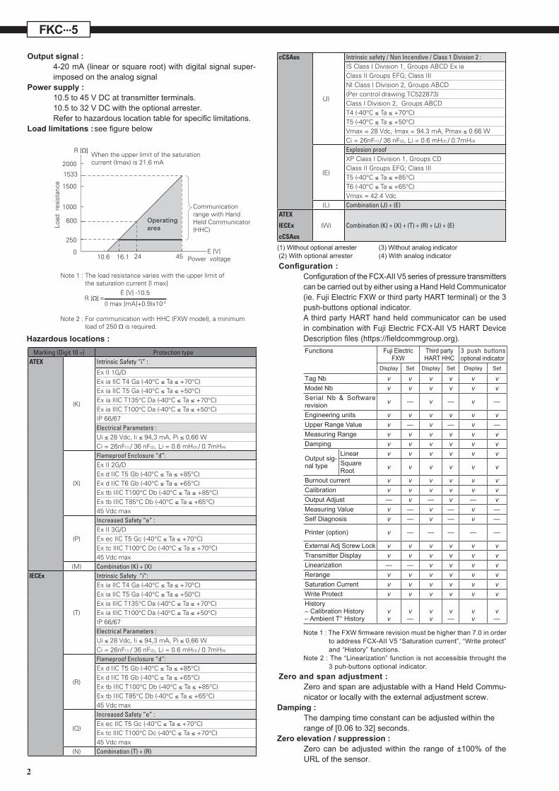
MODEL CODE SYMBOLS 1 2 3 4 5 6 7 8 9 10 11 12 13 14 15 16
5 - - - DESCRIPTIONType
F K C
Differential pressure transmitter - Smart, 4-20 mA + HART/Fuji Electric communication protocols
ConnectionsProcess
connectionsOval flange
threadingElectrical
connectionEnclosure
type
M (*9)(*9)(*9)
1/4 - 18 NPT M10 M20 x 1,5N 1/4 - 18 NPT M10 Pg13,5P 1/4 - 18 NPT M10 1/2 - 14 NPTR (*8)
(*8)
(*8)
(*12)(*12)
(*12)(*1)(*1)
1/4 - 18 NPT 7/16 - 20 UNF M20 x 1,5 "L" shape
"T" shape
T 1/4 - 18 NPT 7/16 - 20 UNF 1/2 - 14 NPT
1/2 - 4 NPT
V (*1) 1/4 - 18 NPT M10 or M12 (*1) Pg13,5W (*1) 1/4 - 18 NPT M10 or M12 (*1)
M10 or M12 (*1)M10 or M12 (*1)
M20 x 1,5X56789
1/4 - 18 NPT
1/4"-18 NPT1/4"-18 NPT1/4"-18 NPT1/4"-18 NPT
Rc 1/4"7/16 - 20 UNF7/16 - 20 UNF7/16 - 20 UNF
7/16 - 20 UNF
Pg13,5
Pg13,5M20 x 1,5
Pg13,5
G 1/2"
Ranges and materials(*2) Static pressure
limitsMeasuring ranges
(*2)Process - cover Measuring
diaphragmWetted cell body
(*3) (*3) LP side HP - side1 1 V
-1 to
32 bar10/100 mm WC
SS 316L SS 316L SS 318LN1 1 W SS 316L Hastelloy C SS 318LN1 1 J SS 316L Gold coat SS 318LN1 1 H SS 316L Hastelloy C Hastelloy C2 2 V
-1 to
100 bar10/600 mm WC
SS 316L SS 316L SS 318LN2 2 W SS 316L Hastelloy C SS 318LN2 2 J SS 316L Gold coating SS 318LN2 2 H SS 316L Hastelloy C Hastelloy C 3 3 V SS 316L SS 316L SS 316L3 3 W SS 316L Hastelloy C SS 316L3 3 H
32 /3200 mm WC
SS 316L Hastelloy C Hastelloy C3 3 M SS 316L Monel Monel lining3 3 J
3 3 C
3 3 C
(*4)
(*4)
SS 316L Gold coating SS 316L
SS 316L Gold/ceramic Gold/ceramic
SS 316L Gold/ceramic Gold/ceramic
3 3 T SS 316L Tantalum Tantalum lining3 5 V
-1
to
160 bar (*3)
SS 316L SS 316L SS 316L3 5 W SS 316L Hastelloy C SS 316L3 5 H
0,13 /13 mm WC
SS 316L Hastelloy C Hastelloy C3 5 M SS 316L Monel Monel lining3 5 J (*4)
(*4)SS 316L Gold coating SS 316L
3 5 T SS 316L Tantalum Tantalum lining3 6 V SS 316L SS 316L SS 316L3 6 W SS 316L Hastelloy C SS 316L3 6 H 0,5/50 m WC SS 316L Hastelloy C Hastelloy C3 6 J (*4)
(*4)SS 316L Gold coating SS 316L
3 6 M SS 316L Monel Monel lining3 6 T SS 316L Tantalum Tantalum lining3 8 V
3/300 m WCSS 316L SS 316L SS 316L
3 8 W SS 316L Hastelloy C SS 31L63 8 J (*4) SS 316L Gold coating SS 316L4 3 V SS 316L SS 316L SS 316L4 3 W SS 316L Hastelloy C SS 316L4 3 H 32/3200 mm WC SS 316L Hastelloy C Hastelloy C4 3 M
-1 to
420 bar
SS 316L Monel Monel lining4 3 J (*4)
(*4)
(*4)
(*4)
SS 316L Gold coating
Gold coating
Gold coating
Gold coating
Gold coating
SS 316L4 5 V SS 316L SS 316L SS 316L4 5 W SS 316L Hastelloy C SS 316L4 5 H 0,13/13 m WC SS 316L Hastelloy C Hastelloy C4 5 M SS 316L Monel Monel lining4 5 J SS 316L SS 316L4 6 V SS 316L SS 316L SS 316L4 6 W SS 316L Hastelloy C SS 316L4 6 H 0,5/50 m WC SS 316L Hastelloy C Hastelloy C4 6 M SS 316L Monel Monel lining4 6 J SS 316L Monel lining4 8 V SS 316L SS 316L SS 316L4 8 W -1
to 300 bar
3/300 m WC SS 316L Hastelloy C SS 316L4 8 J
4 9 J
SS 316L SS 316L
SS 316L SS 316L4 9 V SS 316L SS 316L SS 316L
50/2000 m WC
8 1 H (*5) (*5) (*5) (*5) (*5) (*5) (*5) (*5) (*5) (*5) (*5) (*5) (*5) (*5) (*5) (*5) (*5) (*5) (*5) (*5) (*5) (*5)
10/100 mm WC PVDF Insert Hastelloy C Hastelloy C8 2 H 10/600 mm WC PVDF Insert Hastelloy C Hastelloy C8 3 H
0
to
15 bar
0
to
15 bar
PVDF Insert Hastelloy C Hastelloy C8 3 M 32/3200 mm WC PVDF Insert Monel Monel lining8 3 T PVDF Insert Tantalum Tantalum lining8 5 H PVDF Insert Hastelloy C Hastelloy C8 5 M 0,13/13 m WC PVDF Insert Monel Monel lining8 5 T PVDF Insert Tantalum Tantalum lining8 6 H
0,5 /50 m WC
PVDF Insert Hastelloy C Hastelloy C lining8 6 M PVDF Insert Monel Monel lining8 6 T PVDF Insert Tantalum Tantalum lining9 1 H 10/100 mm WC PVDF Insert SS 316L
SS 316LSS 316LSS 316LSS 316LSS 316LSS 316LSS 316LSS 316LSS 316LSS 316L
Hastelloy C Hastelloy C9 2 H 10/600 mm WC PVDF Insert Hastelloy C Hastelloy C9 3 H PVDF Insert Hastelloy C Hastelloy C9 3 M 32/3200 mm WC PVDF Insert Monel Monel lining9 3 T PVDF Insert Tantalum Tantalum lining9 5 H
0,13 /13 m WCPVDF Insert Hastelloy C Hastelloy C
9 5 M PVDF Insert Monel Monel lining9 5 T PVDF Insert Tantalum Tantalum lining9 6 H
0,5 /50 m WCPVDF Insert Hastelloy C Hastelloy C
9 6 M PVDF Insert Monel Monel lining9 6 T PVDF Insert Tantalum Tantalum lining

7
1 2 3 4 5 6 7 8 9 10 11 12 13 14 15 165 - - - DESCRIPTION
Indicator Arrester 5 - A None None5 - B Analog, 0-100% linear scale None5 - C
C
Analog, 0-100% √ scale
Analog, 0-100% √ scale
Digital, 0-100% √ scale
Digital, 0-100% √ scale
None5 - D Analog, Custom scale None5 - J Analog, double scale None5 - E None Yes5 - F
F
Analog, 0-100% linear scale Yes5 - G Yes5 - H Analog, Custom scale Yes5 - K
K
Analog, double scale Yes
5 - 1 Digital, 0-100% with push button None5 - 2 Digital, Custom scale with push button None5 - 3 Digital, 0-100% √ scale with push button
Digital, 0-100% √ scale with push button
None5 - 4 Digital, 0-100% with push button Yes5 - 5 Digital, Custom scale with push button Yes5 - 6 Yes
5 - L Digital, 0-100% None5 - P Digital, Custom scale None5 - M None5 - Q Digital, 0-100% Yes5 - S Digital, Custom scale Yes5 - N Yes
Hazardous location approvals
(*10)
(*10)
(*11)(*11)(*11)
(*11)(*11)(*11)
(*10)
(*10)
(*10)
(*10)
(*10)
(*13)(*13)
Side vent/drain Mounting bracket
ANone (standard)
NoneCK
SS 304LSS 316L
SS 304LSS 316L
DYes
NoneFL
Stainless Steel partsTAG plate Housing
Y None NoneB Yes NoneC None YesE Yes Yes
Special applications & filling fluidTreatment Filling fluid
Y None Silicone oilW None Fluorinated oilG Degreasing Silicone oilA Oxygen service Fluorinated oil (only with digit 7 = J, V, W)D Chlorine service Fluorinated oil (only with digit 7=H,T)N (*7) NACE Silicone oil
Process cover gasket
- A Viton - C PTFE square section for SS flange - D (*5) PTFE square section for PVDF insert
Bolts/screws materialA Carbon steel Cr-Mo - M10 for static pressure < 160 barU
(*3)
SS 316L / 316L - M10 for static pressure < 160 barV Carbon steel Cr-Mo - M12 for static pressure > 160 barW SS 660/660 - M10 for static pressure < 160 barW
(*7)(*7) SS 660/660 - M12 for static pressure > 160 bar
Special options(*6) - * special, no code available
None
ATEX - Flameproof
ATEX - Intrinsic Safety
ATEX - Increased Safety
ATEX - Combination Flameproof and Intrinsic Safety
cCSAus - Explosion proof
cCSAus - Intrinsic Safety and Non Incendive
cCSAus -Combination Explosion proof, Intrinsic Safety and Non Incendive
IECEx - Flameproof
IECEx - Intrinsic Safety
IECEx - Increased Safety
IECEx - Combination Flameproof and Intrinsic Safety
IECEx - ATEX - cCSAus - Explosion/flameproof, Intrinsic Safety and Non Incendive
A
X
K
P
M
E
J
L
R
T
Q
N
W
Notes*: 1- M12 thread if static pressure > 160 bar.2- Turn down ratio of 100 is possible but span greater than 1/40 of the the URL is recommended for better performances.3- For M10 bolts/nuts : maximum static pressure = 160 bar. For static pressure > 160 bar : M12 is required. 4- Gold coating on wetted parts of the measuring cell for hydrogen service. Gold/ceramic coating available upon request.5- Process cover with PVDF insert: 1/2”-14 NPT side process connection, no vent/drain, square section PTFE gasket. Other upon request.6- When no code can be found in the current model code, place “*” in the corresponding digit code as well as in the 16th digit.7- SS 660 bolts/nuts are in conformity with NACE MR0175/ISO 151568- For static pressure = 420 bar and PTFE process cover gasket, use only code “R”, “T” or “X”.9- Process connection on the bottom side with side vent/drain.10- Only with digit 4 = “M”, “P”, “R”, “T”, “W”11- Except digit 10 = “P”, “Q”12- For static pressure = 420 bar and PTFE process cover gasket, use only code “5”, “6” or “9”13- SS 316L enclosure not available for "T" shape version

8
FKC...5
OUTLINE DIAGRAM (unit : mm) <7th digit code : V, H, M, T>
A
B
C
DIMENSIONS
U-BOLT M8
198,5 225,5 38,5
198,5 225,5 38,5
194 221 37
Vent / drain
A B CD
E
ø15G
ø7
82.
5
ø18.5
R
T
V
W
X
M20x1.5
1/2-14NPT
Pg13.5
M20x1.5
Pg13.5
16
16
10,5
16
10,5
OVAL FLANGE SCREW
7/16-20 UNF
7/16-20 UNF
M10 or M12
M10 or M12
7/16-20 UNF
E GDCode X=4CONDUIT CONNECTION
Zero/Span adjustment screwCONDUIT CONNECTION
(SEE TABLE 1)
WITH ANALOG INDICATOR
WITH DIGITAL INDICATOR
VENT / DRAIN
MOUNTING BRACKET FOR
PIPE Ø50 MM (2”) (X11 = C)
HIGH PRESSURE CONNECTION
1/4 NPT
LOW PRESSURE CONNECTION
1/4 NPT
OVALE FLANGE SCREW
(SEE TABLE 1)
WEIGHT : - 3,5 KG (WITHOUT OPTION) ADD : - 0,3 KG FOR INDICATOR OPTION
- 2 KG FOR STAINLESS STEEL HOUSING OPTION
- 0,5 KG FOR MOUNTING BRACKET
Table 1

9
A
B
C
DIMENSIONS
U-BOLT M8
198,5 225,5 38,5
198,5 225,5 38,5
194 221 37
Vent / drain
A B CD
E
ø15G
ø7
82.
5
ø18.5
R
T
V
W
X
M20x1.5
1/2-14NPT
Pg13.5
M20x1.5
Pg13.5
16
16
10,5
16
10,5
OVAL FLANGE SCREW
7/16-20 UNF
7/16-20 UNF
M10 or M12
M10 or M12
7/16-20 UNF
E GDCode X=4CONDUIT CONNECTION
Zero/Span adjustment screwCONDUIT CONNECTION
(SEE TABLE 1)
WITH ANALOG INDICATOR
WITH DIGITAL INDICATOR
VENT / DRAIN
MOUNTING BRACKET FOR
PIPE Ø50 MM (2”) (X11 = C)
HIGH PRESSURE CONNECTION
1/4 NPT
LOW PRESSURE CONNECTION
1/4 NPT
OVALE FLANGE SCREW
(SEE TABLE 1)
WEIGHT : - 3,5 KG (WITHOUT OPTION) ADD : - 0,3 KG FOR INDICATOR OPTION
- 2 KG FOR STAINLESS STEEL HOUSING OPTION
- 0,5 KG FOR MOUNTING BRACKET
Table 1
Fuji Electric France S.A.S.46 rue Georges Besse - ZI du brézet - 63039 Clermont ferrandTél : 04 73 98 26 98 - Fax : 04 73 98 26 99Mail : [email protected] - web : www.fujielectric.frFuji Electric can accept no responsibility for possible errors in catalogues, brochures and other printed material. Fuji Electric reserves the right to alter its products without notice. This also applies to products already on order provided that such alterations can be made without subsequential changes being necessary in specifications already agreed. All trademarks in this material are property of the respective companies. All rights reseved.
FKC...5
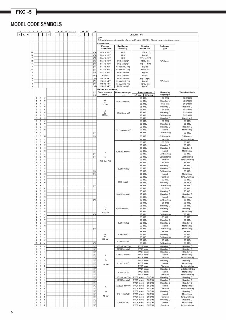
CONNECTION DIAGRAM
ELECTROMAGNETIC COMPATIBILITYAll FCX-AII series of pressure transmitters are in conformity with the provision of the EMC Directive 2014/30/EU on theharmonization of the laws of the Members States relating to electromagnetic compatibility.All these models of pressure transmitters are in accordance with the following harmonized standards :• EN 61326-1 (Electrical equipment for measurement, control and laboratory use - EMC requirements - Part 1: General requirements).• EN 61326-2-3 (Particular requirements - Test configuration, operational conditions and performance criteria for tranducers with integrated or remote signal conditioning).
Emission limits (according to EN 55011 / CISPR 11, Group 1 Class A) Frequency range (MHz) Limits Basic standard 30 to 230 40 dB (µV/m) quasi peack, measured at 10 m distance Passed 230 to 1000 47 dB (µV/m) quasi peack, measured at 10 m distance
Immunity Phenomenon Test value Standard Required Result Performance criteria of criteria Electrostatic Discharge ±4 kV (Contact) EN/IEC 61000-4-2 B A ±8 kV (Air) Radiated, Electromagnetic 10 V/m (0.08 to 1.0 GHz) EN/IEC 61000-4-3 A A Field 3 V/m (1.4 to 2.0 GHz) 1 V/m (2.0 to 2.7 GHz) Fast transients (burst) 2 kV (5/50 ns, 5 kHz EN/IEC 61000-4-4 B A Surge Transients 1 kV Line to line EN/IEC 61000-4-5 B A 2 kV Line to ground Conducted RF Disturbances 3 Vrms (150 kHz to 80 MHz) EN/IEC 61000-4-6 A A 80% AM @ 1 kHz Power Frequency 30 A/m (50 Hz, 60 Hz) EN/IEC 61000-4-8 A A Magnetic Field Performance criteria (A & B): according to IEC 61326