Differential Interference Contrast Attachment for ... · differential interference contrast...
15
DIFFERENTIAL INTERFERENCE CONTRAST ATTACHMENT For TRANSMITTED LIGHT MODEL BH2-NIC INSTRUCTION MANUAL OLYMPUS
Transcript of Differential Interference Contrast Attachment for ... · differential interference contrast...

DIFFERENTIAL INTERFERENCE
CONTRAST ATTACHMENT
For TRANSMITTED LIGHT
MODEL BH2-NIC
INSTRUCTION MANUAL
OLYMPUS
This instruction manual has been written for use of the differential interference contrast attachment Model BH2-NIC.It is recommended to carefu lly read the manual for the microscope Model BHS or BHT as wellas this manual so that you can fully understand and obtain the optimum integrated performanceof this attachment With the microscope in use.
This attachment is specially designed for use with LB series optical elements includingeyepieces, photo eyepieces, and objectives (no other than S Plan objectives, effective forthe Nomarski method) ; otherwise no comple e performance can be obtained from ttusattachme nt.
CONTENTS
I.
II .
III.
IV.
V.
VI.
VII.
VIII.
ABSTRACT .
STANDARD COMPONENTS
PRINCIPLE OF NOMARSKI METHOD A ND INTERF ERENCECONTRAST IMAGE .
1. Principle2. Interference Contrast Image3. Characteristics and Applications of omar i and Phase Contrast Methods .. . .
SPECIFICATIONS
DESCRIPTION OF VARIOUS COMPONENTS . . .
ASSEMBLY . . .
OPERATION .. . .
1. Condenser Centration2. Aligning Phase Annulus and Light Annulus3. Polarizer Centration .4. Light Path Selection5. Interference Contrast .6. Phase Contrast7. Brightfield8. Magnification at Observation and Photomicrography
TROUBLESHOOTING .
2
35
6
7
8
9
10
11
I. ABSTRACT
This differential interference contrast device incorporates a pair of birefr ingent cry stal prismsas beam-splitters, wit h a shear between the two interferi ng beams smaller than the resolut ionlimit of the objective used in the microscope, so that no doub le image is observed.
These attachments, used in conjuncti on w ith a BHS or BHT microscope, permit detect ion ofminu te difference of th ickness and changes of internal ref ract ive index , of unstained, t ransparentspecimens.
By operat ing the birefringent crystal pr ism bu ilt in the intermed iate tube , a most suitab le contrast color can be chosen in accordance w ith purpose and specimen. The background color canbe cont inuously changed in the order from dark to yellow , to purpl ish red, to blue or in the
reversed order.
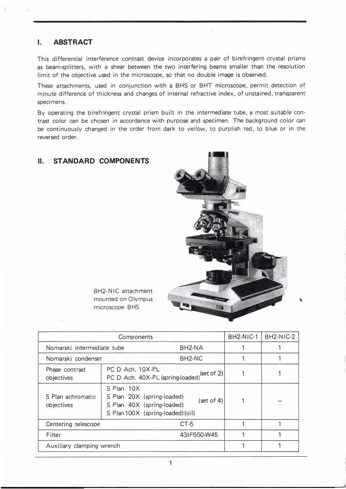
II. STANDARD COMPONENTS
BH2-NIC atta chmentmounted on Olympusmicroscope BHS
Components BH2-NIC-' BH2-NIC-2
Nomarsk i intermed iate tube B H2-NA , ,Nomarsk i condenser BH2-NC 1 1
Phase contrast PC D Ach. 10X-PL ( f 2)1 1
objectives. set 0
PC D Ach . 40X-PL (sprmg-Ioaded)
S Plan lOXS Plan achro mat ic S Plan 20X (spri ng-loaded)
(set of 4) 1objectives S Plan 40X (spring-loaded)
-
S Plan 100X (spri ng-loaded)(oi l)
Centering telescope CT-5 1 1
Filter 431F550 -W45 1 1
Auxiliary clamping wrench 1 1
j

III . PRINCIPLE OF NOMARSKI METHOD AND INTERFERENCE CONTRASTIMAGE
1. Princ iple
"T"he d ifferent ial interference contrast attachment ,after Nomarski , is a two-beam shearing interferencedevice developed on the basis of the Nomarski method , in wh ich t he amount of shear between two interfer ing beams is made less than t he resolution limit ofthe objective used in the microscope, by means ofbirefringent crysta ls used as beam-split ters.
When a ray of light passes through a birefring entcrystal , t he opt ic axis of which is indicated by t hedouble arrow , the ray is divided into two linearlypolar ized rays, an extraordinary ray wh ich runs parallel to the p lane of the diagram, and an ord inarv ray ,whose plane of vibration is perpendicular t o that ofthe extraordinary ray, as shown in Fig. 1.
In Fig. 2, a modi fied Wollaston pri sm consists of twowedge-like un iaxial crystals cemented togeth er, whoseoptic axes are at a right angle t o each ot her. If a rayof linearly polarized light enters the pri sm, it wi II bedivided into two rays trave ling in different directions.
-.,..,E:""""-f---- Ordina ry ray"""i-+-+............... Extrao rdinary
ray
Fig. 1
Plane of frin gelocal izat ion
G
Mod ified Wollast onprism
Fig. 2
, &@ ind icat e the d irect io ns of o ptic axes ;for the d irecti on para llel with the planeof the diagram, and @ fo r the di rect ionperpendicular.
After emerging f rom the pr ism, the two rays intersect at a fixed point . The plane, whichincludes the point o f this intersecti on, is called the plane of " f r inge localizat ion" .
Condense r Cd Ob ject ive ObPo larizer P Ana lyzer A
Wollaston prismon the Cd sid e
Specimen
Wollaston prismon the Ob side
2
Fig. 3

Fig. 3 is a diagram of a light path in which a ray of light emitted from the light source islinearly polarized after it passes through the polarizer P. Entering the Wollaston pr ism onthe condenser side, it is divided into two rays of linearly polarized light. In order to equali zethe intensit ies of the rays and therefore to maximize the contrast of the interference fringes,the Wollaston pr ism must be placed with its optic axis at 45
0to the direction of vi~ration
of the linearly polarized light incident on the prism . The two divided rays intersect at apoint on the plane of f ringe localization, which is calculated to coincide with the focal planeFcd of the condenser Cd. They then pass through t he condenser, become parallel to eachother with a slight lateral separati on and illuminate the specimen . The two rays are transmitted th rough the specimen and the objective which recombines the separate rays at t heplane of fringe local ization of the second Wollaston pr ism on the objec t ive slde. at the rearfocal plane Fob of the object ive Db. The combined rays do not interfere because theirdirections of vibration are perpendicular to each othe r . In order to observe interferencefr inges, an analyzer must be introduced behind the Wollaston prism on the objective side.
A
"//
//
II¢:::=====:'> p
Fig. 4 indicates that the analyzer is placed in a "crossedfilter" position with the polarizer. After the linearly polarized waves "e , " and "e2" as divided by the Wollasto nprism on the condenser side pass through the differentpaths in the specimen as shown in the vector diaqram,their components along the ir directions of polarizationwi ll form interference fringes having maximum visib ility,according to the shear between the two interferingcomponents. If the po larizer P is rotated 450 fro m the Fig. 4
"crossed-filter" posit ion, either "el" or "e2" w ill be blocked , therefore, interf erence fringescannot be formed and an image simila r to a bright fie ld image is observed.If the plane of fringe localizat ion coincides with the rear focal plane of the objective, thespacing of the fringe s becomes infinitely large so that one color fringe f i lls the entire f ieldo f view. When this condition is fulfilled, interference contrast is obtained .
2. Interf erence Cont rast Image
From the view of geometrical optics, two sheared images should be formed in the imageplane of the objective, in other words, in the focal plane of t he eyepiece. However , theyare not recognized as a double image because the amou nt of the shear is too small t o beresolved .
Now consider a specimen with refractive index N2 at positi on A, smaller than the refract iveindex N I at the surroundings B, as shown in Fig. 5. Af ter passing through the specimen,the wavefront W of t he light is divided into two wavefront s, one at position A and theother at position B, advancing at A by d (N2 - N I ) with a sheared amount c;
3

A '
Nl 7 N2 'S( Nt
B B
t t W t
~---- - ,I
I
l) 1 I.r-- - - ---..
/_ ____ -I .
Fig.5 :> X
There occurs a difference between t he opt ical path lengths (or produc ts of the ref ractiveindex " N" and thickness "d " ) at C1 and C2 • Th is difference depends on phasedifferences8 1 and 82 at C1 and C2 , respective ly .There is no difference in background colors at A and B, whi le at C1 and C2 , t he background colors differ, depending upon phase d if ferences at o land 02.
~w is the different ial coefficient of the wavefr ont . These equat ions imply th at the path
d~ference is equal to the prod uct of the shear b. and the different ial coefficient , fro mwh ich is derived the name of "d ifferent ial interference" . By moving the pr ism in the d irect ion as indicated by the arrow in Fig. 6, the pat h difference between two wavefrontsis changed; accordingly the color of the backgro und changes.
Fig. 7 shows the relat ion between the wavef ront s when path di fference 00 is int roducedby the movement of t he prism. In th is case , pat h differences at C1 and C2 are given by
By adjusting the path difference 00, it is possible to observe images similar to dark f ield,relief-like images or sensiti ve color images. .Thus, the best result will be obtai ned by selecting the type of the image suitable for the specimen to be observed.
Direct ion of Wollastonprism movement
Wollaston prism
Fig.6
4
3. Characteristics and App licat ions of Nomarski and Phase Contrast Methods
1) Characterist ics
CD Generally the larger the phase difference, the more conspicuous the halos, wh ich is a drawback of the ordinary phase contrast method, making d ist inct observation of contours moredifficult. The Nomarsk i method does not cause halos, so that a clearer def in it ion of image
details is obtained.
® The Nomarsk i method permits utilization of the full numerical aperture of the objective,which results in exceptional image brightness, and resolut ion almost double that of thelight annulu s used in phase contrast microscopy.
® The depth of focus is smaller in differential interference cont rast than in phase contrast .This prevents disturbing out-of-focus effects, as with phase contrast, and permits layer bylayer scanni ng of specimens, commonly called "optical sectioning " .
@ Interference colors, or grey shadings, can be seen in proportion with the gradient of pathdifferences of the specimen. Phase contrast helps to determine a high or low refract iveindex of a specimen detail by the appearance of halos, according to the positive or negativecontrast of the objective in use .
@ As the shearing direction is restricted in accordance with the sliding direction of theWollaston prism, it is preferable to use a rotatab le stage to orient the specimen in the direction best suited for optimum resolut ion .
® For the observation of anisotropic objects, it is recommended t o apply phase contrastrather than interf erence contr ast for better results.
2) Appl icat ions
The interference cont rast method renders a sharply def ined, relief-like, image with excellent contrast in a wide range of interference colors. This method permits observat ionof unstained transparent objects like phase contrast, which makes it useful for observat ions
. in histology, cytology, biology, anatomy, etc .
IV. SPECIFICATIONS
• Nomarsk i Intermediate Tube
Tube magnification 1.25X; incorporates the modif ied Wollaston prism and analyzer withdepolarizer, both removable.
• Nomarsk i Condenser
Achromatic/aplanat ic condenser N.A. 1.40.Phase cont rast and interference contrast turret w it h 7 apertures, includ ing one empt yopen ing for br ight f ield ; 4 mod ified Wollaston prisms (for lOX, 20X, 40X and 100X objecti ves) and 2 light annul i (for lOX and 40X object ives); centerable by center ing screws.Polarizer built-in , rotatable and removable.Iris diaphragm buil t- in, with aperture adjustment lever.
5
I..
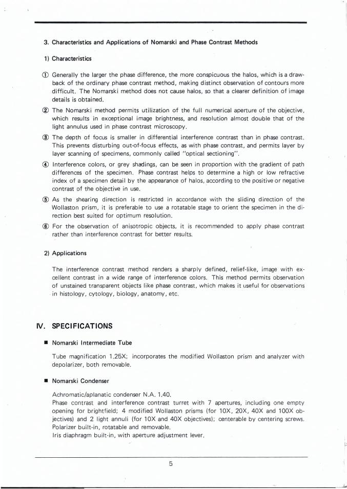
V. DESCRIPTION OF VARIOUS COMPONENTS
A. Nomarski Intermediate Tube BH2·NA
Phase cont rast tu rret
Engravings incl ude" 0" for empty aperture f or br ightf ield ;white letters forphase contrast . andred letters for interference contrast .
Aperture iri s d iaphragmcont ro l lever
Mounti ng dovetai I
Centering knob
Clamping screw
6
Dovetai lmount
Mountinq coll ar~-------~~------
/ / Insert th is collar l n-.> / to the condenser
' mount (36.8mmq,lof the microscope.
Polarizerinsertio n lever
Po larizer rotation/clampi ng screwFit the auxi liaryclamping wrench on to this screw to control the polar izer.
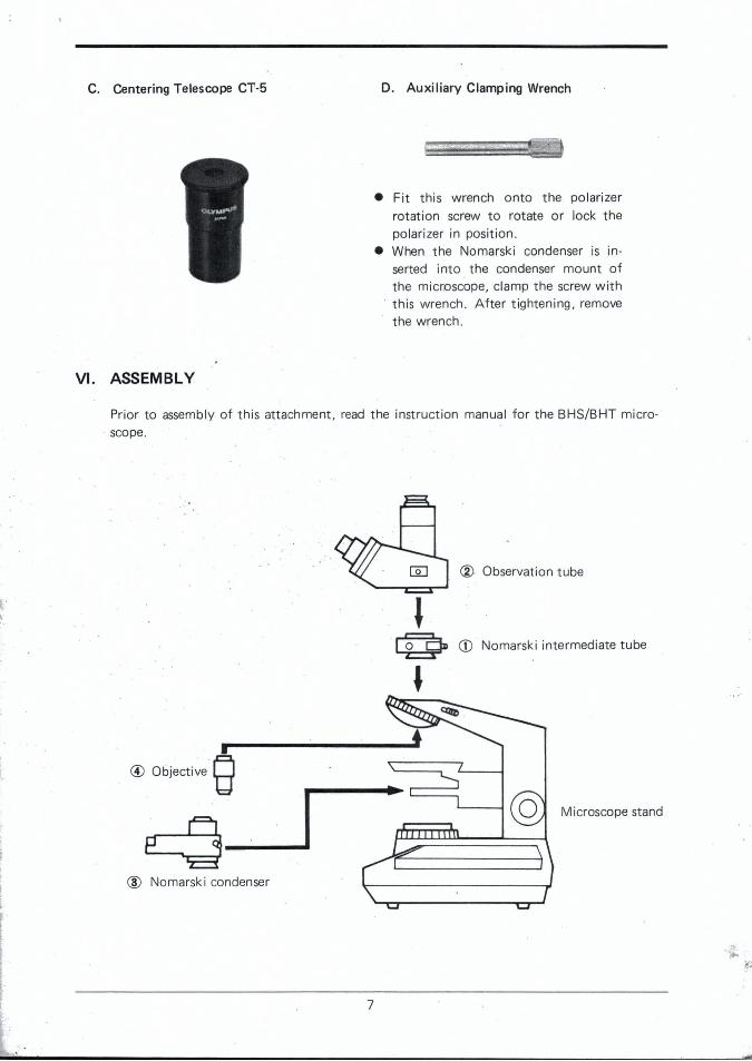
C. Centering Telescope CT-5
VI. ASSEMBLY
D. Auxil iary Clampi ng Wrench
• Fit t his wrench onto the po larizerrotation screw to rotate or lock thepolari zer in positi on.
• When th e Nomarsk i condenser is inserted into the condenser mount ofthe microscope, clamp the screw with
. this wrench. After tighten ing, removethe wrench.
Prior to assembly of this atta chment, read the inst ruct ion manual for the BHS/BHT micro. scope.
.i
•@ Objective 8~_I
® Nomarsk i condenser
7
® Observat ion tube
CD Nomarski intermediate tube
Microscope stand
VII . OPERATION
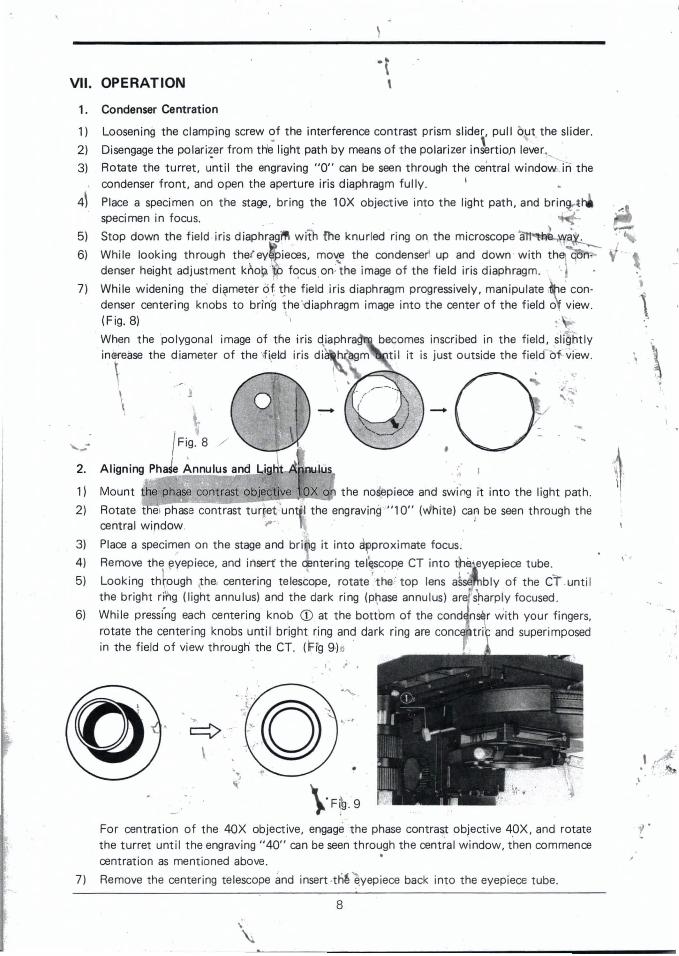
1. Condenser Cent rat ion
~..
y '.,
, f. "1'• • "
,
.'
becomes inscribed in the field, siightlyt il it is just outside the field-bf,·view.
\·F~ . ·9For centration of the 40X objective, engage the phase contrast objective 4~X, and rotatethe turret until the engraving "40" can be seen through the central window, then commencecentration as ment ioned above.
Remove the center ing telescope and insert-the~yep iece back int o t he eyepiece tube .
1) Loosening the clamping screw of the interference contrast prism slider, pull but. the slider .
2) Disengage t he polarizer from th'~ light path by meansof the polarizer i n~rtioJ1 lever.. .,3) Rota te t he turret, until t he engraving "0" can be seen through the central w indowJn the
, condenser front, and open the aperture iris diaphragm fully . '
4\ Place a specimen on the stage, br ing the lOX objective into the light path , and br inlHspecimen in focus .
5) Stop down the f ield ·iris d iaphragilPl with {he knurled 'ring on the microscope at1 ~ ~a .. . t •
6) While looking through the fey ,' ieces, mo'{e the condenser. up and down w ith th c;on-denser height adjustment k~o~ to focus on: the image of the field iris diaphragm. ' .
[. , . ,
7) While widening the' diameter ~f: the field iris diaphragm progressively, manipulate e con-denser centering knobs to brin'g the "d iaphragm image int o the center of the field ot view .
. \(F ig. 8) 1
When the 'po lygonal image of the iris diaphra
J. .
\ ..-' }\ . 0 _ \ ."--"
\ \! Fi9. 8 /
Align ing PhaJe A nnulus and Li9 ~t2.
1) Mount the phase contra st obje ct ive X on the nosepiece and swing it into the light path.
2) Rotate tl1el phase contrast turreCunt :1 the engraving "10" (vJhite) can be seen through thecentral window. r · · ,
.r,
3) Place a specimen on the stage and bri g it int o a~proximate focus.
4) Remove the eyepiece. and insert' the centering telescope CT into tneeyepiece tube .
5) Looking tht~u9h \t he, centering teles~ope, rotate ' the " top lens a~~ bly of the CT .unt i lthe bright ring (light annulus) and the dark ring (phase annulus) ar ' s~a rp IY focused.
6) While press(ng each centering knob CD at the bottom of the cond nser with your fingers,rotate the center ing knobs until bright ring and dark ring are conce tri and superimposedin the field of view through the CT. (F ig 9)~
7)
8
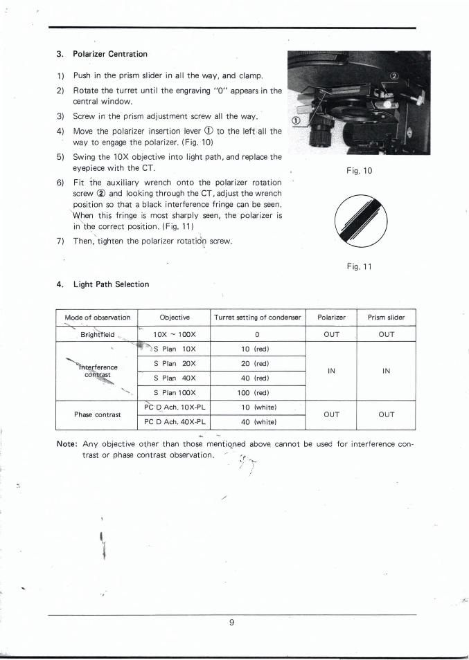
3. Polar izer Centrat ion
1) Push in the pr ism slider in all the way , and clamp.
2) Rotate the t urret unt i l the engraving "0" appears in thecentral w indow.
3) Screw in t he pr ism adjustment screw all the way.
4) Move the po larizer insert ion lever <D to t he lef t- all theway to engage t he polarizer. (Fig. 10)
5) Swing the lOX object ive int o light path , and replace theeyepiece with the CT.
6) Fit t he auxi liary wrench ont o the polar izer rotat ionscrew ® and loo king through the CT , adjust the wrenchposition so that a black interference fr inge can be seen.
'When this fringe is most sharply seen, the polar izer isin the correct position . (Fig . 11)
7) Then ,' t ighten the polarizer rotat idQ screw.
4. Light Path Select ion
Fig. 10
Fig. 11
:'. 1I }
/
Mode of observat ion Objecti ve Turret sett ing of condenser Polarizer Prism slide r-" ~, >-
Bright f ield ~ lOX - 100X 0 OUT OUT-~ ' !,,"J S Plan l OX 10 (red)
""'hterf erence S Plan 20X 20 (red)
cofitcast IN INS Plan 40X 40 (red),
<,,. S Plan 100 X 100 (red)
PC' q.Ach. 10X ·PL 10 (white )Phase contrast OUT OUT
PC 0 Ach. 40X·PL 40 (white )
Note : Any object ive other than those ment iqned above. cannot be used for interference contrast or phase contrast observation .
./
9
rtf
5. Interference Contrast
After comp let ing t he polarizer adjustment so that t he black interference fr inge is mostsharply seen, t ake t he following steps:
1) Choose a most suitable contrast colo r in a range fr om 0 orde r (black) to second order(blue) (or 0 to 700nm) by rotat ing the prism adjust ment screw.
• When the background is dark, darkfie ld-like observat ion is possible.
• When the background is made gray , the visual sensit ivit y to detect small path differenceas a relief-li ke image becomes most pronounced.
• When th e background color is magenta , a change of path d ifference can be most sensit ively detected as a change of color.
* Bear in mind that even th e smallest amount of contamination on th e surface may beshown up because of th e ext reme sensitivity in differential color contrast.
2). Since opt imum resolut ion is achieved on ly if the di rection of the detail s t o be observed isparallel to the pri sm shear, it is recommended to use a rot atable stage (Mod el BH2-SRG).
6. Phase Cont rast
Remove th e prism slider and the pola rizer f rom the light path.
1) Mount the phase contrast objective on t he nosepiece.
2) Center the light annulus . (Refer to " 2. A lign ing Phase Annulus and Light Annu lus" inpage 8.)
3) A fter inserting th e eyep iece into the eyepiece t ube, yo u can perfo rm phase cont rast mi croscopy.
4) The green fi lter provided can be mounted on the filter mount of th e microscope base.It increases cont rast in your observat ion or monochromatic photomicrography .
7. Br ightf ield
Remove the pr ism slider and the polarizer, and rotate the phase contrast t urret until t heengraving "0" is seen through t he centra l window, before you start your br ightfield observation .
8. Magnificat ion at Observation and Photo micrography
1) Observation magnificat ion = Ob]. power X Eyepiece power X 1.25
2) Photomicrography magni fi cat ion = (fo r 35 mm camera)Ob]. power X NFK phot o eyepiece power X 1.25(fo r large format camera)ou. power X NF K phot o eyepiece power X 3 X 1.25
10

VIII. TROUBLESHOOTING
If you are unable to obtain full performance from your instrument , please consult withthe table below as pointers for troubleshooting.
Troubles Causes Remedies
No interference color can be The polari zer is not in the Insert the polar izer into theseen. light path . light path .
The phase contrast turret is Align the turret correctly.not correctly aligned.
The prism slider is not in the Insert the slider into the lightlight path . path .
The interference color can be The height of condenser is Bring the condenser into fo -seen irregularly. not correctly adjusted. cusing position accurately .
The phase contrast turret is Match the magnification ofnot correctly positioned to objective and turret.the magnification of objectivein use.
No designated object ive is Use the designated objectives.used.
The Nomarski intermed iate Correct the direct ion of thetube is mounted in the wrong tube.direction.
Objectives of a wrong type Use S Plan objectives .are used.
No image of field diaphragm The slide glass is too th ick . Use a slide glass less than 1.2is seen. mm thick.
The light annulus and phase No designated phaseobject ive Use designated phase objec -annulus are not matched. is used. tives.
. ~_..i
11

MEMO·········-····----·-·····-·--·--------·---·-··--·· -.. ---..-.. ---.------ - -.. ----- .. --.-..-..- -
12

4-3·~,. HATAG~YA 2.CHOME,SHIBUYA.KUTOKYO, JAPAN.
Printed in Japan 8106 M Oll


![Quantitative differential interference contrast (DIC ... DIC v3.pdf2007. References: Title Microsoft PowerPoint - off-chip DIC v3.ppt [Compatibility Mode] Author Anne Created Date](https://static.fdocuments.net/doc/165x107/5f478857a1b54c464475ddfe/quantitative-differential-interference-contrast-dic-dic-v3pdf-2007-references.jpg)