Differential Global Positioning System (DGPS) Operation ... · Differential Global Positioning...
20
Differential Global Positioning System (DGPS) Operation and Post-Processing Method for the Synchronous Impulse Reconstruction (SIRE) Radar by Francois Koenig and David Wong ARL-TN-0281 June 2007 Approved for public release; distribution unlimited.
Transcript of Differential Global Positioning System (DGPS) Operation ... · Differential Global Positioning...

Differential Global Positioning System (DGPS) Operation and Post-Processing Method for the Synchronous Impulse
Reconstruction (SIRE) Radar
by Francois Koenig and David Wong
ARL-TN-0281 June 2007 Approved for public release; distribution unlimited.

NOTICES
Disclaimers The findings in this report are not to be construed as an official Department of the Army position unless so designated by other authorized documents. Citation of manufacturer’s or trade names does not constitute an official endorsement or approval of the use thereof. Destroy this report when it is no longer needed. Do not return it to the originator.

Army Research Laboratory Adelphi, MD 20783-1197
ARL-TN-0281 June 2007
Differential Global Positioning System (DGPS) Operation and Post-Processing Method for the Synchronous Impulse
Reconstruction (SIRE) Radar
Francois Koenig and David Wong Sensors and Electron Devices Directorate, ARL
Approved for public release; distribution unlimited.

ii
REPORT DOCUMENTATION PAGE Form Approved OMB No. 0704-0188
Public reporting burden for this collection of information is estimated to average 1 hour per response, including the time for reviewing instructions, searching existing data sources, gathering and maintaining the data needed, and completing and reviewing the collection information. Send comments regarding this burden estimate or any other aspect of this collection of information, including suggestions for reducing the burden, to Department of Defense, Washington Headquarters Services, Directorate for Information Operations and Reports (0704-0188), 1215 Jefferson Davis Highway, Suite 1204, Arlington, VA 22202-4302. Respondents should be aware that notwithstanding any other provision of law, no person shall be subject to any penalty for failing to comply with a collection of information if it does not display a currently valid OMB control number. PLEASE DO NOT RETURN YOUR FORM TO THE ABOVE ADDRESS. 1. REPORT DATE (DD-MM-YYYY)
June 2007 2. REPORT TYPE
Final 3. DATES COVERED (From - To)
5a. CONTRACT NUMBER
5b. GRANT NUMBER
4. TITLE AND SUBTITLE
Differential Global Positioning System (DGPS) Operation and Post-Processing Method for the Synchronous Impulse Reconstruction (SIRE) Radar
5c. PROGRAM ELEMENT NUMBER
5d. PROJECT NUMBER
5e. TASK NUMBER
6. AUTHOR(S)
Francois Koenig and David Wong
5f. WORK UNIT NUMBER
7. PERFORMING ORGANIZATION NAME(S) AND ADDRESS(ES)
U.S. Army Research Laboratory ATTN: AMSRD-ARL-SE-RU 2800 Powder Mill Road Adelphi, MD 20783-1197
8. PERFORMING ORGANIZATION REPORT NUMBER
ARL-TN-0281
10. SPONSOR/MONITOR'S ACRONYM(S)
9. SPONSORING/MONITORING AGENCY NAME(S) AND ADDRESS(ES)
U.S. Army Research Laboratory 2800 Powder Mill Road Adelphi, MD 20783-1197
11. SPONSOR/MONITOR'S REPORT NUMBER(S)
12. DISTRIBUTION/AVAILABILITY STATEMENT
Approved for public release; distribution unlimited.
13. SUPPLEMENTARY NOTES
14. ABSTRACT
This report provides a description of the differential global positioning system (DGPS) operation, setup procedure, and post-processing procedure to obtain centimeter accuracy of GPS data for the synchronous impulse reconstruction radar. This highly accurate position information will allow proper focusing of the radar image and will maintain image quality on a moving platform.
15. SUBJECT TERMS
SIRE radar, differential global positioning system
16. SECURITY CLASSIFICATION OF: 19a. NAME OF RESPONSIBLE PERSON
Francois Koenig a. REPORT
Unclassified b. ABSTRACT
Unclassified c. THIS PAGE
Unclassified
17. LIMITATION OF ABSTRACT
SAR
18. NUMBER OF PAGES
20 19b. TELEPHONE NUMBER (Include area code)
301-394-0856 Standard Form 298 (Rev. 8/98) Prescribed by ANSI Std. Z39.18

iii
Contents
List of Figures iv
1. Introduction 1
2. Recommended Operating Procedure 2 2.1 Base Station GPS Setup ..................................................................................................2
2.2 Base Station GPS Shutdown Sequence ...........................................................................5
2.3 Rover GPS Setup.............................................................................................................5
2.4 Rover GPS Shutdown Sequence .....................................................................................6
2.5 Download, Post-process, and Export GPS Data..............................................................6
2.6 Sequence to Download GPS Data from Flash Cards ......................................................6
2.7 Sequence to Post-Process GPS Data ...............................................................................7
2.8 Sequence to Export GPS Time Tags to File....................................................................7
2.9 Obtaining Base Station Data Without a Local Base Station .........................................10
3. Summary 11
References 12
Appendix 13
Distribution List 14

iv
List of Figures
Figure 1. Example of base station setup with Z-Surveyor (left) and rover antenna on the roof of mobile platform with Z-Surveyor unit stored inside the vehicle (right). ................................ 4
Figure 2. The front (left) and rear (right) panels of Z-Surveyor unit............................................. 4 Figure 3. Example of Eval32 showing the number of space vehicles in sky chart (top palette),
current base station location (bottom right palette), and display of main console (bottom left palette)..................................................................................................................................... 5
Figure 4. Example of the GrafNav data conversion utility............................................................ 8 Figure 5. Example of the GrafNav differential data-processing utility. ........................................ 8 Figure 6. Example of unprocessed (top) versus post-processed (bottom) data of the same GPS
location. (Note that the resolution of the unprocessed data shown on top is at 2 m per block, while the resolution of the post-processed data on the bottom is at 2 cm per block.) . 9
Figure 7. Example of the Dload32. (The left palette window shows the raw data file on the flash card, while the right palette shows the files downloaded from the card.) ............................ 10

1
1. Introduction
The global positioning system (GPS) jointly developed by the Department of Defense, the Department of Transportation, and the National Aeronautics and Space Administration was fully functional by 1995. The system has three major components: space, earth control, and end user. The space component consists of a constellation of 24 satellites arranged in such a way that they circumnavigate the earth in six orbital planes, each with four satellites at any given time. Therefore, on average, a typical receiver on earth can track 7 to 12 satellites at any given time of the day. Each satellite continuously transmits encrypted information via carrier signal over L1 and L2 bands at 1,575.42 and 1,227.6 MHz, respectively, to GPS receivers so users can precisely identify their location on earth by the triangulation principle. However, most systems will be able to provide sufficient positioning information by tracking just five orbiting satellites. The control component on earth is a worldwide network of monitoring stations that provides the status of each satellite in orbit. The control stations periodically upload important information such as atmospheric condition, trajectory information, and almanac data to the satellites. If necessary, each satellite uses the information to self-correct and adjust for proper operation. Finally, the end user component is the GPS receiver that has the capability to process the signal transmitted by the satellites for accurate positioning or navigation. Users with sophisticated software can create virtually unlimited applications. Commercial uses such as precision farming, emergency locator service, and intelligent vehicle navigation are among a few applications that are now possible.
For even greater accuracy, a user can implement a differential GPS (DGPS) solution (1). The principle behind DGPS is to use the reference location of the base receiver to correct for the error position of the unknown rover position. Since the base station is fixed, we can use the difference between the measurement of the base and the rover receivers to create an error correction vector. The precise location of the rover can then be calculated if we apply the error correction over all the satellite data. DGPS can be achieved through real-time telemetry links between a base and a rover or through post-processing the data. Real-time methods include a) medium frequency beacon differential service, b) L-Band satellite differential service, c) frequency modulation sub-carrier differential service, or d) on-site, radio frequency telemetry link. All the real-time services have a coverage area and a range limitation and require a local radio/receiver to obtain the transmitted service. Method d requires operation of a transmitter by the user in addition to the radio/receiver. Post-processing differential techniques only require the use of two GPS receivers with storage capacity. The kinematic post-processing method relies on the base station as the reference receiver and the rover as the unit that can move around without restriction. The user will post-process the data on a computer after the GPS data have been collected. Generally, centimeter resolution is possible with this technique, whereas the non-DGPS can only achieve a

2
resolution of a few meters. Therefore, DGPS with kinematic post-processing is a preferred method of tracking motion when accuracy and precision are a major issue.
The two units that we use for DGPS are Z-Surveyor1 receivers from Ashtech. They feature 12 parallel channels that receive coarse acquisition (C/A) code phase and full wavelength carrier phase measurement on L1 frequency (1575 MHz), precise (P) code phase and full wavelength carrier phase on L1 and L2 frequency (1227 MHz). We use Waypoint’s GrafNav2 software to post-process the GPS data. When the post-processing is completed, the radar data, along with the GPS information, are combined into a pre-focus data file in the lab. The positioning data extracted from the GPS give motion compensation (MOCOMP) information and track the radar position during the experiment. This will allow focusing of the data (2) where height and position of targets can be calculated relative to the position of the radar in the image.
2. Recommended Operating Procedure
The following operating procedures provide consistent differential GPS data for the synchronous impulse reconstruction (SIRE) radar data collection (3). Raw position data are recorded at a 0.1 second rate onto a flash card in the GPS units to be downloaded later, differentially processed and cross referenced with time tags stored with the radar data.
2.1 Base Station GPS Setup
1. Set up base station GPS antenna on a level tripod and measure the height of the antenna above ground (see figure 1).
2. Install charged battery into base Z-Surveyor unit (see figure 2). Connect Port A of Z-Surveyor to laptop with serial cable (figure 2).
3. Login to laptop: xadministrator; password _______________
or thinkpad: uwbradar; password _______________.
4. Ensure base Z-Surveyor is connected to antenna.
5. Turn on Z-Surveyor by pushing the power button on left of unit. “Sysinfo” message will display on the front panel for a few seconds.
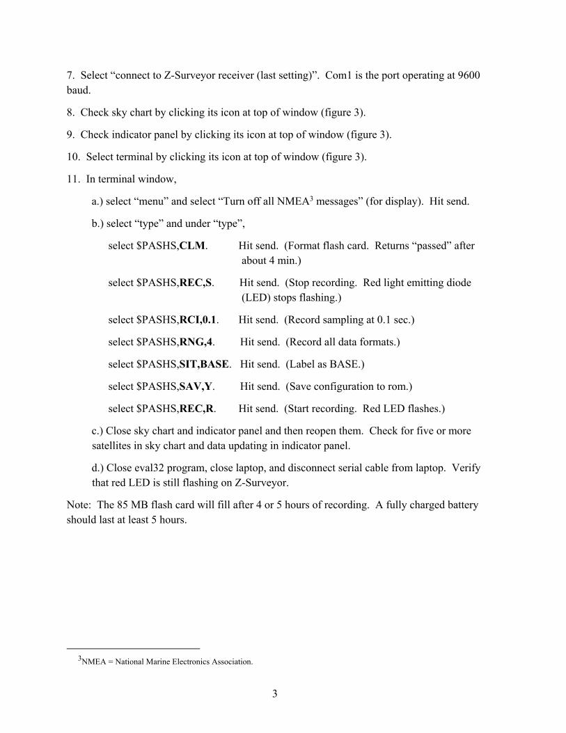
6. Run eval32 on laptop (see figure 3).
1Z-Surveyor is a trademark of Magellan, Corporation. 2Grafnav is a trademark of NovAtel, Inc.
3
7. Select “connect to Z-Surveyor receiver (last setting)”. Com1 is the port operating at 9600 baud.
8. Check sky chart by clicking its icon at top of window (figure 3).
9. Check indicator panel by clicking its icon at top of window (figure 3).
10. Select terminal by clicking its icon at top of window (figure 3).
11. In terminal window,
a.) select “menu” and select “Turn off all NMEA3 messages” (for display). Hit send.
b.) select “type” and under “type”,
select $PASHS,CLM. Hit send. (Format flash card. Returns “passed” after about 4 min.)
select $PASHS,REC,S. Hit send. (Stop recording. Red light emitting diode (LED) stops flashing.)
select $PASHS,RCI,0.1. Hit send. (Record sampling at 0.1 sec.)
select $PASHS,RNG,4. Hit send. (Record all data formats.)
select $PASHS,SIT,BASE. Hit send. (Label as BASE.)
select $PASHS,SAV,Y. Hit send. (Save configuration to rom.)
select $PASHS,REC,R. Hit send. (Start recording. Red LED flashes.)
c.) Close sky chart and indicator panel and then reopen them. Check for five or more satellites in sky chart and data updating in indicator panel.
d.) Close eval32 program, close laptop, and disconnect serial cable from laptop. Verify that red LED is still flashing on Z-Surveyor.
Note: The 85 MB flash card will fill after 4 or 5 hours of recording. A fully charged battery should last at least 5 hours.
3NMEA = National Marine Electronics Association.

4
Figure 1. Example of base station setup with Z-Surveyor (left) and rover antenna on the roof of mobile platform with Z-Surveyor unit stored inside the vehicle (right).
Figure 2. The front (left) and rear (right) panels of Z-Surveyor unit.
Rover antenna Base antenna
Up/Down Button
Battery Slot
Flash Memory Card Slot
On/Off AC Power Button
Display Panel
Connects to AC Power
Port A connects to PC Com1 serial port
For rover unit only – Port B connects to timing control card, sub miniature version A port
Connects to GPS antenna
5
Figure 3. Example of Eval32 showing the number of space vehicles in sky chart (top palette), current base station location (bottom right palette), and display of main console (bottom left palette).
2.2 Base Station GPS Shutdown Sequence
1. Turn off Z-Surveyor unit.
2. Remove flash card. Never pull out flash card while recording (red LED is flashing).
3. Remove battery and put into charger.
4. Remove GPS antenna from tripod and stow.
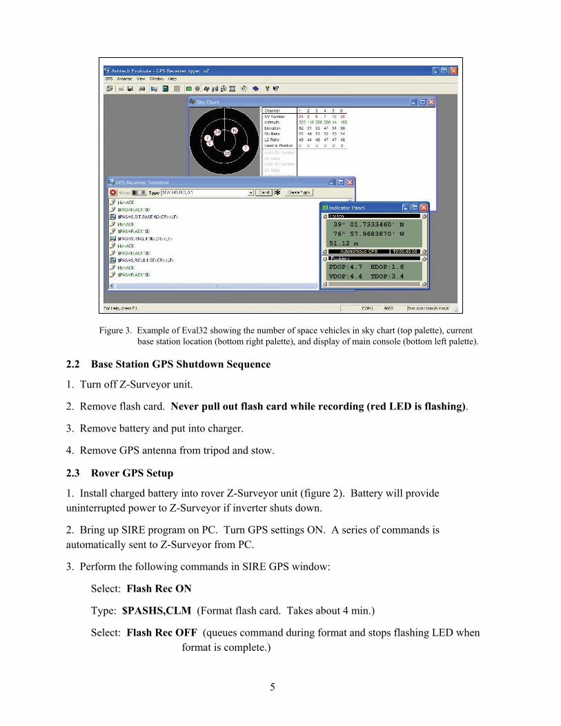
2.3 Rover GPS Setup
1. Install charged battery into rover Z-Surveyor unit (figure 2). Battery will provide uninterrupted power to Z-Surveyor if inverter shuts down.
2. Bring up SIRE program on PC. Turn GPS settings ON. A series of commands is automatically sent to Z-Surveyor from PC.
3. Perform the following commands in SIRE GPS window:
Select: Flash Rec ON
Type: $PASHS,CLM (Format flash card. Takes about 4 min.)
Select: Flash Rec OFF (queues command during format and stops flashing LED when format is complete.)

6
Select: Flash Rec ON (start recording session.)
Rover Z-Surveyor will continue to collect data on flash card until stopped or shut off. It continues recording even if software is stopped. Never pull out flash card while recording (red LED is flashing).
2.4 Rover GPS Shutdown Sequence
1. Turn off Z-Surveyor unit.
2. Remove flash card.
3. Remove battery and put into charger.
2.5 Download, Post-process, and Export GPS Data
After the test is completed, the GPS data stored in Ashtech’s data format are downloaded from the flash memory card onto a laptop computer (see section 2.6). We then convert the base and rover data, which contain carrier phase, position, ephemeris, site information and time stamp of each epoch, into Waypoint’s GrafNav format (see section 2.6 and figure 4). The GrafNav software is a high precision post-processing engine that supports static and kinematic modes (see figures 5 and 6). We use the kinematic method to post-process the data shown in figure 6. The top figure shows the “zoom-in” raw un-processed aperture position of the rover at a site, and the bottom figure shows the same data apertures after post-processing. In general, the post-processed data show a dramatic improvement of the aperture position, where centimeter resolution is possible. Note that the scale on each square is 2 m on each side for the un-processed data, while the post-processed is 2 cm on each side. Clearly, as shown in the figure 6, the resolution is quite good for tracking motion.
When the kinematic post-processing step is completed, we convert the location output to our local radar coordinate system and store it in an text file. In GrafNav, the motion data are processed in the World Geodetic System 1984 (WGS84) format, which is similar to the latitude and longitude lines on maps. However, depending on the type of application, the motion data can be converted to universal transverse mercator, local X, Y, and Z or any standardized coordinate system (see section 2.8). The final step in the post-processing is to take the text file with the motion data and perform an exhaustive cross-reference to align them to the radar data by matching the time stamps stored previously.
2.6 Sequence to Download GPS Data from Flash Cards
1. Create dated, descriptive top-level folder on laptop for download files. Create subfolder “Base” for base station files and “Rover” for mobile GPS files.
2. Run dload32 command (see figure 7). Select the flash card drive for source data. Select corresponding folder on C: drive for destination, either “Base” or “Rover”. Drag the file name from the source area to the destination area.

7
3. The user can provide the base antenna height in the program after completion of base download. Information will be stored for later use in the GrafNav post-processing program.
2.7 Sequence to Post-Process GPS Data
1. Run GrafNav program on PC. Requires software protection dongle.
2. Select “Convert raw GPS to GPB4” (figure 4) (for base station data)
3. Find folder for base files and select “add all”.
4. Select “global options” and uncheck “make all epochs kinematic”. Select convert.
5. Select “Convert raw GPS to GPB” (figure 4) (for rover data).
6. Find folder for rover files and select “add all”.
7. Select “global options” and check “make all epochs kinematic”. Select convert.
8. Select “file, new project”. Provide new configuration file name.
9. Select “file, add master GPB file” (converted base station data). Open base file in base directory. Add base antenna height, if missing.
10. Select “file, add remote GPB file” (converted rover data). Open a rover file in rover directory.
11. Select “Process, Process Differential” (figure 5). Under process tab, “auto” should be checked and under general tab, data interval is 0.1 (s). Click “process” button.
2.8 Sequence to Export GPS Time Tags to File
1. Perform differential post-processing according to previous section.
2. Select Output menu, Export Wizard.
3. Pick an output file name and the SIRE GPS data profile.
4. Accept the defaults and hit next. When asked for local time parameters, enter 4 if daylight saving time or 5 if eastern standard time. Hit finish to process.
4GPB refers to a .gpb file which is a proprietary format for Grafnav binary data.

8
Figure 4. Example of the GrafNav data conversion utility.
Figure 5. Example of the GrafNav differential data-processing utility.

9
Figure 6. Example of unprocessed (top) versus post-processed (bottom) data of the same GPS location. (Note that the resolution of the unprocessed data shown on top is at 2 m per block, while the resolution of the post-processed data on the bottom is at 2 cm per block.)
Post-processed data
Unprocessed data

10
Figure 7. Example of the Dload32. (The left palette window shows the raw data file on the flash card, while the right palette shows the files downloaded from the card.)
2.9 Obtaining Base Station Data Without a Local Base Station
There are rare occasions when the base station GPS data collection fails because of hardware malfunction, operator error, or depleted batteries/memory space. In many cases, an alternate source of base station data can be obtained to salvage the differential post-processing step. We should attempt to find a recording site as close as possible to the rover position to minimize differences in atmospheric conditions and dilution of precision (DOP). In the following example, we select the base station at the Naval Observatory in Washington, DC, as close to rover operation at the Army Research Laboratory, Adelphi, Maryland.
1. Go to the web site, http://www.ngs.noaa.gov/cgi-cors/corsage.prl?site=GODE.
2. Select Standard Files on the left menu.
3. Select DC Washington, USNO as site (Naval Observatory), RINEX2 Data as option, enter date of interest and select find files.
4. Note: Hourly base station data from the Naval Observatory will be combined into one file, *.06o.gz, after a day. Within one day of test date, you may need to individually download *.06o.Z files for each hour of the test and combine them into one file using GrafNav option. Files cannot be combined and resampled in one step. The user must combine files into one file first, then resample at the 0.1-sec rate.
5. In order to combine or resample, run GrafNav.

11
6. From the file menu, select “GPB Utilities: Concatenate, Splice, or Resample.”
7. Select “add file(s)”, select output file, indicate whether you are resampling. If resampling, the rate will be selected on the next window. Hit “go” for processing.
3. Summary
Centimeter accuracy of position data were obtained through the proper use of a differential GPS solution. A GPS receiver (rover) was installed on the SIRE platform and a stationary (base station) GPS receiver was set up in the test area to collect data simultaneously. After completion of the data collection, the two GPS sources are imported into the GrafNav software, a high precision post-processing engine, to generate a differential GPS output. Finally, the results are exported to a file for cross-referencing with time tags embedded into the radar data. The differential GPS provides the essential positioning information needed to allow the SIRE radar data to be focused in a known coordinate system.

12
References
1. Understanding GPS Principles and Applications, Elliott D. Kaplan, editor. 1996 Artech House, Inc.
2. Nguyen, L.; Wong, D.; Ressler,M.; Koenig, F.; Stanton, B.; Smith, G.; Sichina, J.; Kappra, K. Obstacle Avoidance and Concealed Target Detection Using the Army Research Lab Ultra-Wideband Synchronous Impulse Reconstruction (UWB SIRE) Forward Imaging Radar. Proceedings of SPIE, Detection and Remediation Technologies for Mines and Minelike Targets XII, April 2007.
3. Ressler, M.; Nguyen, L.; Koenig, F.; Smith, G. Synchronous Impulse Reconstruction (SIRE) Radar Sensor for Autonomous Navigation. Army Science Conference, November 2006.

13
Appendix
Common GPS Command Sequences for Z-Surveyor
GPS Position (refer to Z-Surveyor front panel in figure 2):
1. ↑ <2 sec until survey:<mode> 2. ↓ >2 sec select survey:<mode> and go to submenu 3. ↑ <2 sec until status 4. ↓ >2 sec select status and go to submenu 5. ↑ <2 sec until LAT: N/S xx◦xx’xx.xxxxx”
Lon: E/W xxx◦xx’xx.xxxxx” ALT: xxxxx.xxx scrolls across the screen.
Satellite Tracking:
1. ↑ <2 sec until survey:<mode> 2. ↓ >2 sec select survey:<mode> and go to submenu 3. ↑ <2 sec until status 4. ↓ >2 sec select status and go to submenu 5. ↑ <2 sec until #USED: xx
Remaining Memory:
1. ↑ <2 sec until sysinfo 2. ↓ >2 sec select sysinfo and go to submenu 3. ↑ <2 sec until MEM:xxx%
Remaining Power:
4. ↑ <2 sec until sysinfo 5. ↓ >2 sec select sysinfo and go to submenu 6. ↑ <2 sec until BAT:xxMIN
Note: ↑ or ↓ refer to corresponding buttons on front of GPS unit (figure 2). <2 sec or >2 sec refer to depressing button for less than or more than two seconds. ↑ >2 sec returns to upper level menu.

14
Distribution List
ADMNSTR DEFNS TECHL INFO CTR ATTN DTIC-OCP (ELECTRONIC COPY) 8725 JOHN J KINGMAN RD STE 0944 FT BELVOIR VA 22060-6218
DARPA ATTN IXO S WELBY 3701 N FAIRFAX DR ARLINGTON VA 22203-1714
OFC OF THE SECY OF DEFNS ATTN ODDRE (R&AT) THE PENTAGON WASHINGTON DC 20301-3080
US ARMY TRADOC BATTLE LAB INTEGRATION & TECHL DIRCTRT ATTN ATCD-B 10 WHISTLER LANE FT MONROE VA 23651-5850
SMC/GPA 2420 VELA WAY STE 1866 EL SEGUNDO CA 90245-4659
US ARMY INFO SYS ENGRG CMND ATTN AMSEL-IE-TD F JENIA FT HUACHUCA AZ 85613-5300
COMMANDER US ARMY RDECOM ATTN AMSRD-AMR W C MCCORKLE 5400 FOWLER RD REDSTONE ARSENAL AL 35898-5000
US ARMY RSRCH LAB ATTN AMSRD-ARL-CI-OK-TP TECHL LIB T LANDFRIED (2 COPIES) BLDG 4600 ABERDEEN PROVING GROUND MD 21005-5066
DIRECTOR US ARMY RSRCH LAB ATTN AMSRD-ARL-RO-EV W D BACH PO BOX 12211 RESEARCH TRIANGLE PARK NC 27709
US ARMY RSRCH LAB ATTN AMSRD-ARL-D J M MILLER ATTN AMSRD-ARL-CI-OK-T TECHL PUB (2 COPIES) ATTN AMSRD-ARL-CI-OK-TL TECHL LIB (2 COPIES) ATTN IMNE-ALC-IMS MAIL & RECORDS MGMT ATTN AMSRD-ARL-SE-RU F KOENIG (4 COPIES) ATTN AMSRD-ARL-SE-RU D WONG (2 COPIES) ATTN AMSRD-ARL-SE-RU K KAPPRA ATTN AMSRD-ARL-SE-RU G KIROSE ATTN AMSRD-ARL-SE-RU M RESSLER ATTN AMSRD-ARL-SE-RU C TRAN ADELPHI MD 20783-1197