Diezel Tube Amp Service Manual V1 - Diezel · PDF fileService Manual . 2 Please note: This is...
51
1 Diezel Tube Amp Service Manual
Transcript of Diezel Tube Amp Service Manual V1 - Diezel · PDF fileService Manual . 2 Please note: This is...

1
Diezel Tube Amp Service Manual

2
Please note: This is a service manual specifically for service departments and official repair centres. This is NOT a manual for do-it-yourself people and unskilled beginners. There are lethal high voltages inside the amplifier. Unplug the amp from the wall power and wait for a minimum of 10 minutes before You start servicing. Be sure your workbench is clean and there are no material or surfaces that could act as ground potential between the technician and the high voltages found in this equipment. Use an isolating transformer between the wall power and the power input on the amplifier if it is necessary to control voltages or to bias the amp. While you are controlling voltages inside the amp it is advisable to keep one hand in the pocket of your trousers to avoid shock.
We are not responsible for any damage to your health, to the Diezel amplifier, or any external unit.

3
Content
Biasing Page 4 Biasing a VH4 Page 5 Biasing a Diezel amp with external bias jacks Page 8 Biasing a Diezel amp with no external fuses Page 8 Biasing a Diezel amp with no external fuses and Page 9 no external bias jacks Replacing components on Diezel PCB´s Page 10 Replacing PCB´s on Diezel amps Page 10 Common issues on early Diezel amps: Bad filter caps Page 11 Malfunction on midi controller chips Page 15 Broken LED´s Page 19 Burned VH4 tube fault LED´s and resistors Page 24 Tube sockets and their clamps Page 26 Mains transformer input wiring Page 27 Fuses Page 31 Replacing the hum trim pot on the VH4(S) Page 34 Tubes Page 36 Pulling power tubes Page 38 Tube layouts Page 39 Block diagram Page 42 Maximum power consumption Page 43 Midi, XLR and footswitch connectors Page 44 Einstein switching jacks Page 45 Schmidt switching jacks Page 46 Guitar input impedance Page 47 Loop levels and impedance Page 47 Trouble shooting first simple steps Page 48 How to order schematics and parts Page 49 Modifications: Less compression and more presence for earlier VH4 Page 50 Noise when using phantom power on early Hagen Page 51

4
Biasing First verify that
To bias a tube amp there is a need for a multi meter with 200 milliamps setting. Be safe that the fuse inside the unit is not blown. Please allow the tubes to warm up for 5 minutes.

5
Biasing a VH4: Using the cathode measurement method: First, remove the fault fuse. Locate the measurement points as on the photo below. They are between ground and the upper connection to the LED resistor which is connected to pins 1 and 8 on the power tube socket.

6
Adjust the bias trim pot with a small screwdriver to approximately 35 milliamps on the multi-meter:
Insert tube fuse 1 and repeat procedure for tubes 2, 3, and 4. It is normal for this measurement to vary over a range of 5 ma between the tubes. The lowest bias/reading for any individual tube should be 35ma.

7
Using the shunt method: Connect your measurement leads as shown in the picture below. Measurements can be taken between either the red and the yellow, Or the red and the blue wires.
Turn the amp on and set amp run, (Standby off). Now adjust to 65ma on your meter. This method is different to the cathode measurement method in that you do not get the screen grid current.

8
Biasing a Diezel amp with external bias jacks: If you have an amp with external bias jacks just remove the back cover and follow the instruction printed on the rear plate.
Biasing a Diezel amp with no external fuses: Some early amps have the tube fault fuses inside on the PCB board. Take the chassis out of the head shell and follow the instruction printed on the PCB. Remove one fuse and connect your measurement line to both contacts of the fuse holder. Adjust the current with the adjacent bias trim pot. Insert the fuse and repeat procedure with the next tube fault fuse. It is advisable to repeat this procedure two or three times to insure accuracy.

9
Biasing a Diezel amp with external fuses and no external bias jacks: Take the chassis out of the head shell and follow the instructions on the PCB. An example is shown below. The location of the measurement points and trim pots will differ between the different Diezel amplifiers.

10
Replacing components on Diezel PCB´s Since we use double layer boards in most cases it is not necessary to take out the whole board for replacing components or other repairs. It may be simpler cut and/or break out the bad component and re-solder to the solder pads. Cut the legs on the new component if necessary for accurate fitting..
Replacing PCB´s on Diezel amps If you receive a new board, we recommend first taking photographs of the inside of the amplifier before the repair to insure the correct wiring. Some times we will send new pots within the board. Use these new pots for best functionality. Begin the board replacement by cutting the legs of the power tube sockets. There is an opening in the board to reach the upper legs on the sockets. Do not worry about damaging the old sockets, we will send You new power sockets:
11
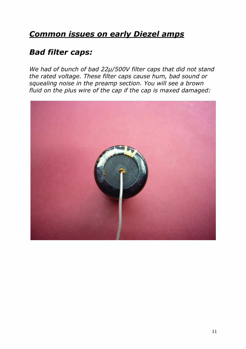
Common issues on early Diezel amps
Bad filter caps: We had of bunch of bad 22µ/500V filter caps that did not stand the rated voltage. These filter caps cause hum, bad sound or squealing noise in the preamp section. You will see a brown fluid on the plus wire of the cap if the cap is maxed damaged:

12
The filter caps are easy to replace. Cut the cable tie and the leads on the cap. There is also some glue between the board and the component. Gently break the cap out:

13
25Replace the cap with a proper substitute checking for correct polarity orientation and glue it on the board to avoid movement.
Solder the legs to the solder pads.

14
To avoid further damage to the caps we recommend to replace one resistor in the power supply. This a resistor with 2,2k ohm / 9 watt as in the picture below:
Replace this resistor with a 4,7k ohm / 5 watt type:
Please solder this new resistor with a bit distance from the board of the generated heat of this component. The extra space from the board will aid in heat dissipation. For procedure see “Replacing Components”.

15
Malfunction on midi controller chips If there is a malfunction on the midi functionality, replace first the 40 pin IC controller chip shown in the picture below:
Please note: Until 2005 we used the AT89S8252 which had two 33pF caps beside the oscillator quartz. Since 2005 the manufacture stopped production and released the AT89S8253 which needs two 4,7pF ceramic caps on the oscillator. In case we send you the new controller, replace the 33pF caps with 4,7pF.

16
Simply cut the old caps, and re-solder the new 4,7pF caps to the same solder pads:
Now solder the 4,7pF caps in:

17
Other midi issues can be caused by the quartz (silver coloured component) located near the controller or the opto coupler located on the big main PCB or on the smaller back PCB. The couplers are either 6 pin PC900 or H11F1 types:

18
If you do not have a special tool to remove the old controller chip, alternate prying each end out bit by bit with a small screw driver until the chip comes free:
Check for orientation (half circle tab), and set the new chip. Lastly push the unit snug in the socket.

19
Broken LED´s If you have a broken LED on Herbert, we recommend a 20 milliamps translucent type as substitute. To replace the LED take the amplifier out of the head shell and remove the bad LED within the black housing with a small cutter:
20
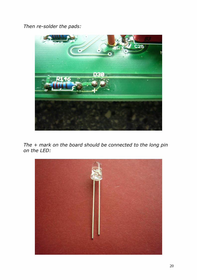
Then re-solder the pads:
The + mark on the board should be connected to the long pin on the LED:

21
Shorten the pins on the LED a bit for good fit, and solder the LED to the board. Bend the leads to get the LED through the hole in the front panel. Be sure that both leads do not touch or are shorted by an insertion tool:

22
To avoid further damage to all LED´s, we recommend that the pre-resistors are reeplaced. These resistors are located close to the LED´s as shown in the previous photo. Use 2,2k ohm / 0,5 watt types. Cut the old resistors from the board, remove the old leads from the board and solder the new resistors in. Cut the leads on the new resistors to fit:

23
To find the resistors please see pictures. They are located close to the LED´s and their value is 680 ohm / 0,5 watt or 470 ohm / 0,5 watt.

24
Burned VH4 Fault LED´s and resistors If a tube fault LED is not working on an early VH4, the LED itself is bad and the pre resistor is burned like in the photo below:

25
Replace the LED with a blue lightning and translucent type. It should be a 5mm/20mA type. The pre resistor should be a 100 kilo ohm / 2 watt type. On the next picture shows how to connect the parts. The plus leg of the LED is connected to the resistor and the resistor is soldered to the cathode of the power tube. The minus leg of the LED leads to the silver ground wire:

26
Tube sockets and their clamps If tubes are replaced frequently, it is possible that the clamping action of the contacts inside the tube sockets can become loose and loose their contact with the tube pins. If this is the case the amp may not work or sound bad with some “fizzy” distortion. It is possible to re-tension the clamps with a small tool or very small screw driver. Please be very careful ! If the socket is damaged is has to be replaced. FIRST UNPLUG THE AMP !!!

27
Mains transformer input wiring
We use two different types of mains transformers on the amps. Type 1:
There are two wires coming from the power switch. Let´s call them AC1 and AC2. The left side of the transformer is the primary input. The pins are 1 from left bottom to 8 at left top. Pin 9 is ground. Primary winding one is: Pin 1 : 0V Pin 2 : 100V Pin 3 : 115V Pin 4 : 120V Primary winding two is: 5 : 0V 6 : 100V 7 : 115V 8 : 120V

28
Both primary windings should be connected to your local mains voltage. For 100V connect AC1 to pin 1 and AC2 to pin 2. Connect pin 1 to pin 5 and pin 2 to pin 6. For 117V/120V connect AC1 to pin 1 and AC2 to pin 4. Connect pin 1 to pin 5 and pin 4 to pin 8. For 220V/230V connect AC1 to pin 1 and AC2 to pin 7. Connect pin 3 to pin 5. For 240V connect AC1 to pin 1 and AC2 to pin 8. Connect pin 4 to pin 5. Type 2:

29
Mains transformer type 2 has also two primary windings: Primary one: Yellow : 0V Green : 100V Blue : 115V Grey : 120V Primary two: Black : 0V Brown : 100V Red : 115V Pink or violet : 120V On the PCB there are 10 solder pads: TRA1, TRA2, CP1 (or CP close to TRA1), CP2 (or CP close to TRA2), 2 x CS and 4 x NU. Wires that are not used please solder to the NU pads. NU means “not used”. The wiring schematic is: 100V: TRA1 = Yellow TRA2 = Green CP1 = Black CP2 = Brown 117V/120V: TRA1 = Yellow TRA2 = Grey CP1 = Black CP2 = Pink or violet

30
220V/230V: TRA1 = Yellow TRA2 = Red CS = Blue CS = Black 240V: TRA1 = Yellow TRA2 = Pink or violet CS = Grey CS = Black Be sure that the main fuse has the correct value !!! The values are shown on the rear panel located close to the mains jack. We use 5 by 20 millimetres slow blow European style fuses. In the USA you can get the fuses from Mouse Electronics or the local electronic parts dealer.

31
Fuses The mains fuse is located underneath of the mains jack:
There is also a spare fuse. If a fuse is blown there is a reason like a short inside the amp !

32
The tube fault fuses are on the rear panel. The tube fault indicators are either red or blue. If the indicators are on, the tube fault fuse is blown. The fuse is switches off a pair of tubes, so the power amp works symmetrically. An exception is the VH4(S). There is a single fuse for each individual power tube.
Below is a list of amp function if a tube fault fuse is blown: 20, 30, 50 watt power amp : No more volume 100 watt power amp: Less volume, weak sound 150 watt power amp: Less volume, weak sound 300 watt power amp: Less volume, weak sound If this happens we recommend to replace the fuse(s) and the power tubes. Please note: Not all tube issues are covered by the tube fault fuse(s).

33
To avoid exploded fuses and broken parts inside the fuse holder we recommend ceramic fuses:
The fuses are 5 by 20 millimetres slow blow European types. You can get them in an electronic store or at Mouser. Fuses are 0,5 amps slow blow on all amps exceptional on the VH4(S). Here we use 0,25 amps slow blow. Internal fuses are 8 amps, 2 amps and 1 amp slow blow. If they are blown there is a reason and need for a skilled repair.

34
Replacing the hum trim pot on the VH4(S) Power tubes with a heater short can destroy the hum trim pot on the VH4(S). This will cause a hum in the preamp. It is possible to replace the hum trimmer by a 100 ohm / 0,5 watt type but we recommend to use a 47 ohm / 2 watt and a 100 ohm / 2 watt resistor.
Remove the trim pot with a solder iron and refresh the 4 solder pads on the PCB:

35
Now solder the 47 ohm resistor and the 100 ohm resistor in. The 47 ohm resistor is the left one:
These resistors can also be burned by a bad power tube but are more rebust than the trim pot.

36
Tubes Please note that also brand new tubes can also be broken. Power tubes: Most common issues on power tubes are shorts with or without lightning, red plating, micro phonics, loss of power, and intermitted loss of power. They also can introduce hum into the power stage or the pre amp stage. Power tubes with heater short can destroy the hum trimmer on the VH4(S). Depending on the design a power tube will max out after 5000 to 20000 hours. It is unlikely you will recognize the difference in sound if you do not hear a new power tube side by side. On our recommended tubes you should have a bias current of 35 milliamps each tube. Most of our amps adjust a pair of output power tubes with one bias trim pot, or 70 milliamps for each pair. Please see chapter biasing. We do not recommend the “big bulbs” like KT88, 6550 or KT66 in our amplifiers. These tubes need a higher bias rating. This will result in unnecessary heat in the mains transformer. Preamp tubes: Preamp tubes can produce hum, crackling, loss of power and a large amount of white noise. They wear out after a few thousand hours of working time. In our amps require VERY low micro phonic types on V1 and V2. V1 is located in the slot closest to the input jack.

37
Our recent recommend tubes: Power tubes : KT77-JJ Preamp tubes: V1 = 12AX7AC5 HG+ 678 V2 = 12AX7AC5 HG+ V3 to V6 or V7 or V9 (depending on model) = 12AX7AC5 HG Reverb tube: 12AT7-C You can order the tubes at your local dealer and always at Ruby Tubes in USA, Banzai in Europe and from Diezel. If you order from Diezel we need: The serial number of the amp, Your address and phone number. Please send this information to [email protected] and we will send You a proforma invoice with our bank information to wire the money. At the moment there is no payment through credit card or Paypal.

38
Tube layouts VH4: V1 = input stage for all channels V2 = channel 4 V3 = channel 2,3,4 V4 = all channels V5 = mixer and send buffer V6 = return driver serial and parallel V7 = phase inverter VH4S: V1 = input stage for all channels V2 = channel 4 V3 = channel 2,3,4 V4 = all channels V5 = mixer and send buffer V6 = return driver serial and parallel side A V7 = return driver serial and parallel side B V8 = phase inverter side A V9 = phase inverter side B For very early VH4: V1 = input stage for all channels V2 = clean channel V3 = channel 3 and 4 V4 = channel 2 and 4 V5 = all channels V6 = mixer and send buffer V7 = return driver serial and parallel V8 = phase inverter

39
For very early VH4S: V1 = input stage for all channels V2 = clean channel V3 = channel 3 and 4 V4 = channel 2 and 4 V5 = all channels V6 = mixer and send buffer V7 = return driver serial and parallel side A V8 = return driver serial and parallel side B V9 = phase inverter side A V10 = phase inverter side B Herbert: V1 = input stage and channel 2 V2 = channel 3 V3 = all channels V4 = mixer and send buffer V5 = return driver serial and parallel V6 = phase inverter Hagen: V1 = input stage, channel 2 and 3 V2 = channel 4 V3 = all channels V4 = mixer and send buffer V5 = return driver serial and parallel V6 = phase inverter

40
Einstein 50 and Einstein 100: V1 = input stage, channel one mode 1 and 2 V2 = channel 2 V3 = all channels V4 = mixer and send buffer V5 = return driver serial and parallel V6 = phase inverter Einstein Combo: V1 = input stage, channel one mode 1 and 2 V2 = channel 2 V3 = all channels V4 = mixer and send buffer V5 = return driver serial and parallel V6 = phase inverter V7 = reverb driver and return Schmidt: V1 = input stage and channel 3 V2 = all channels V3 = reverb driver and return V4 = loop buffer and return V5 = phase inverter

41
Pulling power tubes We do not recommend pulling power tubes because this will lead to a mismatching on the power transformer. To mismatch the output impedance do not help in this case.

42
Block diagram

43
Maximum power consumption
30 watt models: 160 watts 50 watt models: 230 watts 100 watt models: 370 watts 150 watt models: 500 watts

44
Midi, XLR and footswitch connectors Midi in: Pin 3 and pin 7 = 12VDC / plus / max. 0,7A Pin 1 and pin 6 = ground / minus Pin 4 = 5V / midi data Pin 5 = midi data Midi thru: Pin 2 = ground Pin 4 = 5V / midi data Pin 5 = midi data XLR (Columbus footswitch): Pin 1 = ground / minus Pin 2 = 12VDC / plus / max. 0,7A Please note that the current for two connected units should not exceed 0,7A ! FS5S, FS7HE, FS7HA: These jacks work only with the recommend Diezel footswitches using a one wire system. Please do not connect latching switches !

45
Einstein switching jacks Connect common latching types. LED`s can be powered across both pins on the switch. Use correct polarity. Connect your external switching as noted below: Channel / master stereo jack: Tip = channel / Ring = master 2 / Sleeve = corresponding Master mono jack: Tip = master 2 / Sleeve = corresponding Reverb mono jack: Tip = reverb / Sleeve = corresponding

46
Schmidt switching jacks Use only momentary latch switches. No LED power possible. Stereo jack 1: Tip = channel 1 / Ring = channel 2 / Sleeve = corresponding Stereo jack 2: Tip = channel 3 / Ring = loop / Sleeve = corresponding Mono jack 3: Tip = reverb / Ring = corresponding Not many midi switchers are able to switch the Schmidt between the 3 channels and activate and reactivate the loop and reverb. We have had good experience with the RJM Gizmo midi switcher. Set it to momentary latching and “group” the first 3 outputs for switching between channel 1,2 and 3 on the Schmidt.

47
Guitar input impedance Impedance more than 500 kohm Please use a good quality guitar cable for best performance. Cable capacity should not exceed 300pF.
Loop levels and impedance Send:
Send levels are up to +4dB depending on channel volume and guitar output. Start by setting the volume knobs at noon. DC send resistance is approximately 4,7 kohm. Buffer impedance is approximately 600 ohm. Return: DC resistance and impedance about 47 kohm. -10 dB minimum voltage for full power amp output.

48
Trouble shooting first simple steps

49
How to order schematics and parts We can provide service centres or repair centres with schematics and parts. Please note: We send schematics only without values of the components. You will see the value on individual components or on the PCB. If You have a burned component or burned PCB area please contact us for information. To order a schematic or parts we require the following information: 1. Name of the company 2. Address of the company (don´t forget the country) 3. Your phone number 4. The serial number of the amp 5. The version number of the PCB You are working on. For example “Einstein-Mainboard-V1.5” Without this information we cannot start the procedure !
Most spare parts are available in your country ! Of course we are always here to assist you, but it would make repairs easier and faster if we do not have to ship parts from Germany. Please try to support us a bit in this case. We would be very pleased.
Service centres are always welcome ! Please provide us with complete information and charges.
Our contact address is: [email protected]

50
Modifications: Less compression and more presence for earlier VH4 In this case replace the resistor in the picture below to 330 kohm / 0,5 watt. If you also want to add more low end to the power amp insert a 0,1µF / 250 volt cap in the white feedback wire coming from the 8 ohm speaker out jacks. If the white wire is connected to the 4 ohm jacks rewire it to the 8 ohm speaker outputs.
51
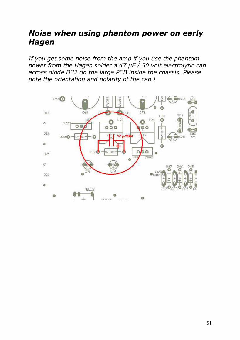
Noise when using phantom power on early Hagen If you get some noise from the amp if you use the phantom power from the Hagen solder a 47 µF / 50 volt electrolytic cap across diode D32 on the large PCB inside the chassis. Please note the orientation and polarity of the cap !