
Diesel Mechanics - Eric - U.S. Department of Education · PDF file82 C01010. DIESEL MECHANICS...
249
ED' 220 6,31 AUTHOR TITLE INSTITUTION PUB DATE NOTE AVAILABLE FROM DOCUMENT RESUME CE 033 516 Foutes, William Diesel Mechanics: 9uel Systems. Mid-America Vocational Curriculum Consortium, Stillwater, Okla. 82 284p.; For related documents see tb 149 162 and CE 033 514-515. Mid-America Vocational Cuiriculum Consortium, 1515 West Sixth Avenue, Stillwater, OK 74074. EDRS PRICE MF01 Plus Postage. PC Not Available from EDRS. DESCRIPTORS *Auto-. Mechanics; Behavioral Objectives; Curriculbm Guides; *Diesel Engines; Job Skills; Learning Activities; Performance Tests; Postsecondary Education; Trade and Industrial Education; Transparencies IDENTIFIERS *Fuel Systems ABSTRACT This publication is the third in a series of three texts for a diesel mechanics curriculum. Its purpose is to teach the concepts related to fuel injection systems in a diesel trade. The text contains eight units. Each instructional unit irjcludes some or all of these basic components: unit and specific (fiFtormance) objectives, suggested activities for teachers and students, information sheets, transparency masters, assignment sheets, answers to assignment sheets, job sheets, pencil-paper and performance tests, and answers to tests. Introductory matei.ia,ls include description of unit components, instructional/task analysis (psychomotor and cognitive skills to be learned), listing of needed tools and equipment, and reference list. Unit titles are Introduction to Fuel Injection Systems, Fuel System Components, Distributor Type Injection Pump, In-Line Injection Pump, Unit Injector, Pressure Time (PT) Fuel Systems, Injection Nozzles, and Governors. (YLB) *********************************************************************** Reproductions supplied by EDRS are the best that can be made from the original document. ***********************************************************************
Transcript of Diesel Mechanics - Eric - U.S. Department of Education · PDF file82 C01010. DIESEL MECHANICS...
ED' 220 6,31
AUTHORTITLEINSTITUTION
PUB DATENOTE
AVAILABLE FROM
DOCUMENT RESUME
CE 033 516
Foutes, WilliamDiesel Mechanics: 9uel Systems.Mid-America Vocational Curriculum Consortium,Stillwater, Okla.82284p.; For related documents see tb 149 162 and CE033 514-515.Mid-America Vocational Cuiriculum Consortium, 1515West Sixth Avenue, Stillwater, OK 74074.
EDRS PRICE MF01 Plus Postage. PC Not Available from EDRS.DESCRIPTORS *Auto-. Mechanics; Behavioral Objectives; Curriculbm
Guides; *Diesel Engines; Job Skills; LearningActivities; Performance Tests; PostsecondaryEducation; Trade and Industrial Education;Transparencies
IDENTIFIERS *Fuel Systems
ABSTRACTThis publication is the third in a series of three
texts for a diesel mechanics curriculum. Its purpose is to teach theconcepts related to fuel injection systems in a diesel trade. Thetext contains eight units. Each instructional unit irjcludes some orall of these basic components: unit and specific (fiFtormance)objectives, suggested activities for teachers and students,information sheets, transparency masters, assignment sheets, answersto assignment sheets, job sheets, pencil-paper and performance tests,and answers to tests. Introductory matei.ia,ls include description ofunit components, instructional/task analysis (psychomotor andcognitive skills to be learned), listing of needed tools andequipment, and reference list. Unit titles are Introduction to FuelInjection Systems, Fuel System Components, Distributor Type InjectionPump, In-Line Injection Pump, Unit Injector, Pressure Time (PT) FuelSystems, Injection Nozzles, and Governors. (YLB)
***********************************************************************Reproductions supplied by EDRS are the best that can be made
from the original document.***********************************************************************

82 C01010
DIESEL MECHANICS :FUEL SYSTEMS
by
William Foutes'
revised by
Bill GuynesJoe Mathis
Marvin Kukuk
Developed by the
Mid-America Vocational Curriculum Consortium, Inc.
U.S DEPARTMENT OF EDUCATIONNATIONAL INSTITUTE OF EDUCATION
EOUCA T1ONAL RESOURCES INFORMATION
NflCENTER ERIC)
Tho document has been reproduced as,eceNed from the Orson or organuabon
Of vna togMaw), ;hangel have been made I0 th,OrOve
,ef),X1UCtiOn quality -
Poonts Of wore Or OthrsOrts stated el thn dOCu
relent do not necessanN reennent offIclaINIEOOStIton or Wive,
Board of Directors
Merle Rudebusch., Nebraska, ChairmanDavid Poston, Louisiana, Vice ChairmanAmon Herd, Missouri, Parliamentarian
James Dasher, ArkansasBill Barnes, Colorado
Les Abel, KansasPat Lindley, Texas
[pan Elwood, South DakotaBob Patton, Oklahoma
Alan Morgan, New MexicoLarry Barnhiardt, North Dakota
Ann Benson, Executive Director
"PERMISSION TO REPRODUCE THISMATERIAL IN MICROFICHE ONLYHAS BEEN GRANTED BY
TO THE E8CATIONAL RESOURCESINFORMA N CENTER (ERIC)"

>
alb /
1 v
1
4 t
-
,
tOPYRIGHT - 1982
Mid-America Vocational Curriculum Consortium, Inc.
..
Printed by
.:.-
...
,
Oklahoma State Department of Vocational and Technical Education
Stillwater, Oklahoma 74074
J
, s
'9
/
1
,
.02,
TABLE OF CONTENTS
Unit I Introduction to Fuel Injection Systems 1D: FS-1
Unit II ruel System Componems , , D: FS-11
Unit III Distributor Type Injection Pump D: FS-41
Unit IV InLige I rijectiohl5Timp D: FS-85
'Unit V Unit Injector D FS-149i 1
Unit VI PT Fuel'Systems D: FS.201
Unit VII Injection Nozzles D FS-253' o
Unit VIII Governors D FS-275
a
O
o
FOREWORD.
The Mid-America Voational Curriculum Consortium (MAVCC) was organized for thepurpose of developing instructional materials for its eleven member states. All memberstates participate.in establishing annual development priorities, and the need for curriculumin diesel mechanics truly reflects regional needs.
Diesel Engine Mechanics was originally 'produced in 1977. Since that time, technologyas related to equipment and methods has changed. To keep .abreast of these changes,MAVCC has revised this book into three shorter publications.
..Diesel Mechanics: Fuel Systems is the third publication ,. of a series of three textsdedicated to a diesel mechanics curnculum. Although it can be taught as a single text, it isdesitned to be used in conjunction with Diesel Mechanics. Electrical Systems and DieselMechanics: Fundamentals to provide continuity in student training. Other MAVCC publica-tions entitled Hydraulics. and Power Trains will broaden the scope of the diesel training.Another use of this book is to supplement the training of an auto mechanics student whomay later be working on diesel powered automobiles. It is hoped that this effort will provideindustry with truly well trained technicians for the world of diesel and the varied skills itdemands.
The success of 'this publication is due, hl large part, to the capabilities of the personnelwho worked with its development. The technical writers have numerous years Of industry aswell as teaching experience. Assisting them in their efforts were, representatives of each ofthe member states who brought with them:technical expertise and the experience relate'd tothe classroom and to the trade. ,To assure that the materials would parallel the industryenvironment and be acceprted as a transportable basic teaChing tool, organizations and in-dustry representatives were involved in the developmental phases of the manual. Apprecia-tion is extended to them for their valuable contributions to the manual.
Instructional materials in. this publication are written in terms of student performanceusing measurable objectives. Thisis an innovative approach to teaching that accents and aug-ments the teaching/learning process. Criterion referenced evaluation instruments are pro-vided for uniform measurement of student progress. In addition to evaluating recall informa-tion, teachers are encou'raged to evaluate the other areas inclUding process and product asindicated at the end of each instructional unit.
It is the sincere belief of the MAVCC personnel and all those members who servedon the committees that this Publication will allow the students to become better preparedand more effective members of the work force.
v
Merle RudebtIsch, ChairmanBoard of DirectorsMicliAmerica Vdcational
Curriculum Consortium

it.
PREFACE
Both the development and revision of instructional materials in diesel mechanics have beenrewarding efforts because of the talented people who planned and wrote the materials.From the team of teachers, industry representatives, and trade and'industrial staff memberswhose combined years of experience in the diesel trade total over 260 years has come aseries of texts which should offer diesel mechanics students an excellent opportunity forlearnirfg required skills.
4 ,
The title of this third book of the series, Diesel Mechanics: Fuel Systems indicates,that thisbook is dedicated to teaching the concepts related to fuel injection systems in a diesel trade.Naturally, this book is designed to be used with other MAVCC books related to diesel.These include Diesel Mechanics: Electrical Systems, Diesel Mechanics: Fundamentals,Power Trains, and Hydraulics.
As complex .as some mechanical activities are, the MAVCC format presents the proceduresin logically ordered objectives that facilitate a comfortable learning rate. The format alsofrees the instructor to concentrate on reinforcing classroom instruction with films, fieldtrips, and other activities that serve to maintain student interest at a high level and motivatestudents to learn and do.
Despite careful planning and editing, we know that the text may perhaps contain a typo-graphical error or ,two. Letting us know when you find such items will be a great help inimproving the prodtict before reprint time. But most of all, your input about the majorelements in the book will be valuable help for changing or adding objectives when thematerials are again revised and updated.
We respond to your suggestions, and we hope the quality of the MAVCC materials related todiesel will serve a positive role in the classroom and.provide industry with the skilled people
,that are so needed.
,
4.
,
Ann BensonExecutive DirectorMid-America Vocational
Curriculum Consortium
.-

ACKNOWLEDGEMENTS
Appreciation is extended to those individuals who contributed their time and talents to thedevelopment of Diesel Mechanics: Fuel Systems.
The contents of this pu,blication were planned and reviewed by:
Mid-America Vocational CurricuWm Consortium Committee
Cliff OlsonDean CarterJohn DagelCharles CramtonKen CondorTed ModicaGary SnelsonDavid GoodacreJim ThompsonBin Augustqarwin Hutzen
Devils Lake, North DakotaMalvern, ArkansasWatertown, South DakotaWest Wego, LouisianaAurora, ColoradoAlbuquerque, New MexicoSpringfield, MissouriDrumright, OklahomaBeloit, KansasMilford, NebraskaAustin, Texas
Thanks are extended to Ron Simmons for representing teacher education on this committeeand to Donnie Tuminello for representing state supervisory personnel.
Special thanks are-extended to Harlan Gjoraas of the Kearns Machinery Company and Doug.MacDonald of Technical Systems, Inc. for their representation of industry on the committeeand to the numerous other companies who provided references and.technicai materials.
Gratitude is expressed to-Jane Huston and P.J. 'Colbert for editing and to Mary Kellum andDan Fulkerson for their assistance in editing and proofreang.
The Graphics Division lof the Pklahoma State Department of Vocational ald TechnicalEducation is deserving of much credit for typing, providing artwork, and printing thispublication.
Special appreciation is extended to those who served on the original advisory committeerepresenting the many MAVCC states.

a
USE OF THIS PUBLICATION
Instructional Units
Diesel Mechanics: Fuel Systerni includes eight Units. Each instruCtional unit includessome or all of the basic 'components of a unit of instruction: performance objectives,suggested activities for teachers and students, information sheets, assignment sheets, jobsheets, visual aids, tests, and answers to the test. Units are planned,for more than ope lessonor class period of instruction.
Careful study of each instructional unit bi the teacher will help to determine:
A. The amount of material that can be covered in each class periodB. The skills which must be demonstrated
1. Supplies needed2. Equipment neededa. Amount of practice Deeded4. Amount of class time needed for.demonstrations
C. Supplementary materials -such as pamphlets or filmstrips that must be orderedD. Resource people who must be contacted
Ob'ectives
Each unit of instruction is based on performance objectives. These objectives state thegoals of the course, thus providing a sense of direction and accomplishment for the student.
Performance objectives are stated in `two forms: unit obje,ctives, stating the subjectmatter to be covered,in a unit of instruction, and specific objectives, stating the student per-
. formance necessary to reach t,he unit objective.
Since the objectives of the unit provide direction for the teaching-learning process, .itis important for the teacher and Students to have a common understanding of the intent ofthe objectives. A limited 'lumber of performance terms have been_used in the objectives forthis curriculum to assist in promoting the effectiveness of the communication among allindividt.i)is using the materials.
Following is a list of performance terms and their synonyms which may have been usedin this material:
NameLabelList in writingList orally
, LetterRecordRepeat
6 Give
Identify DescribeSelect DefineMark Discuss in writingPoint out Discuss orallyPick out I nterpretChoose Tell howLocate Tell whatLabel Explain
xi
...
- .:' "
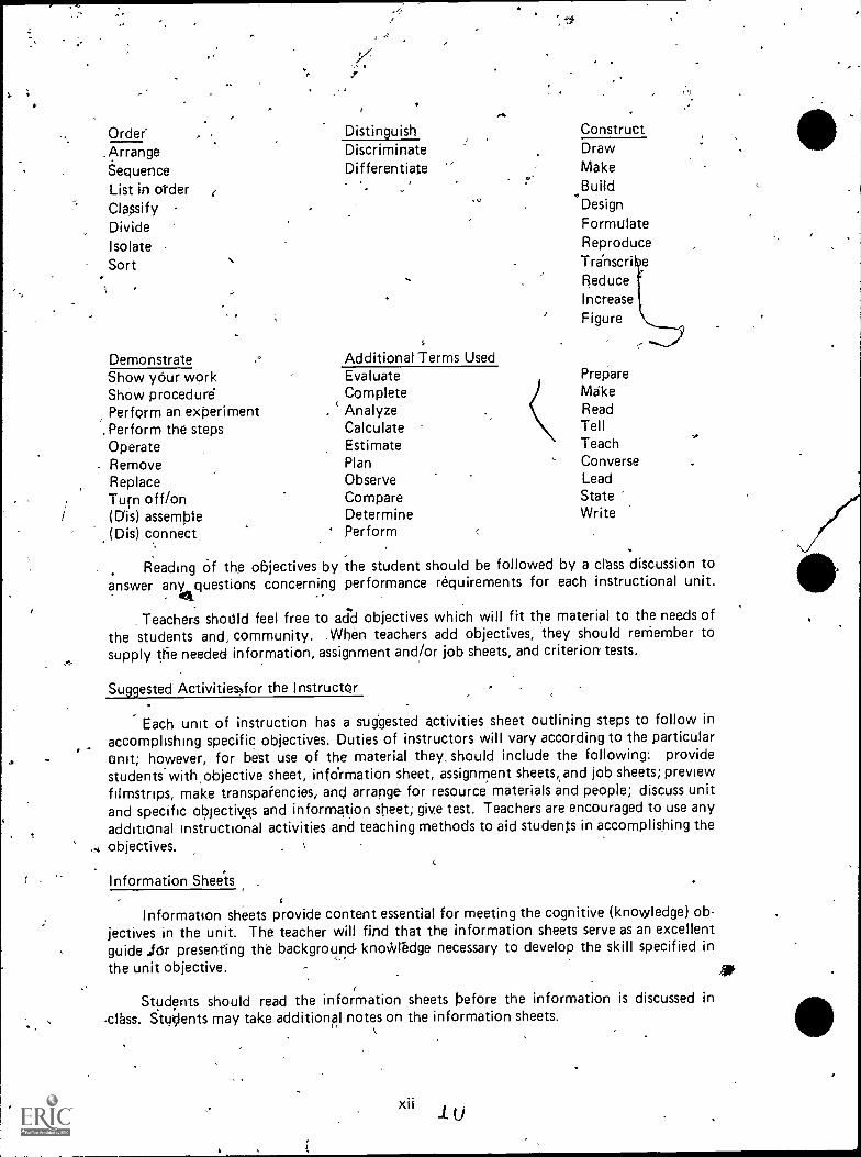
Order'.ArrangeSequenceList in olderClassify ,
DivideIsolateSort
i .
c
\
,
Distingu ishDiscriminateDifferentiate
. .,
k 0
Demonstrate ,. Additional Terms UsedShow your work EvaluateShow procedure CompletePerform an experiment . ' Analyze
. Perform the steps CalculateOperate EstimateRemove Plan
Replace Observe
/Turn off/on Compare(Dis) assemble Determine(Dis) connect Perform ,
Reading Of the objectives by ihe student should be followed by a class discussion toanswer any questions concerning performance requirements for each instructional unit.
da.
Teachers should feel free to acid objectives which will fit the material to the needs of
the students and, community. When teachers add objectives, they should remember tosupply ttie needed information, assignment and/or job sheets, and criterion tests.
_
ConstructDrawMakeBuildDesign
FormulateReproduceTranscri eReduceIncreaseFigure
PrepareMakeReadTellTeachConverseLeadStateWrite
Suggested Activities,for the Instructor
,Each unit of instruction has a suggested activities sheet outlining steps to follow in
accomplishing specific objectives. Duties of instructors will vary according to the particularunit; however, for best use of the material they, should include the following: providestudents-with objective sheet, infOrmation sheet, assignment sheets( and job sheets; previewfilmstrips, make transpafencies, and arrange for resource materials and people; discuss unitand specific objectivss and information sheet; give test. Teachers are encouraged to use anyadditional instructional activities and teaching methods to aid students in accomplishing theobjectives.
Information Sheels -
Informatton sheets provide content essential for meeting the cognitive (knowledge) ob-jectives in the unit. The teacher will find that the information sheets serve as an excellentguide for presenting the background knoWlbdge necessary to develop the skill specified in
the unit objective. -. 41P
Students should read the informatf ion sheets before the information is discussed in,class. Stu1ents may take additional notes on the information sheets.
,
411
Transparency Masters
Transparency niasters provide informatidn in a special way. The students may see aswell as hear the material being presented, thus reinforcing the learning process. Transparen-cies may present new information or they may reinforce information presented in the in-formation sheets. They are particularly effective when identification is necessary.
Transparencies should be made and placed in the notebook where they will be imme-diately available for use. TransParencies direct the class's attention to the topic of discus-sion. They should be left on the screen only when topics shown are under discussion.
..>
Joel Sheets
Job sheets are an important segment of each unit. The instructor should be able toand in most situations should demonstrate the skins outhned in the job sheets. Proceduresouthned in the job sheets give direction to the skill being taught and allow both student andteacher to check student progress toward the accomplishment of the skill. Job sheetsprovide a ready outline for students to follow if they have missed a demonstration. Jobsheets ako furnish potential employers witil a picture of the skills being taught and theperformances which might reasonably be expected from a person who has had this training.
Assignment Sheets
Assignment sheets give direction to study and furnish practice for paper and pencilactivities to develop the knowledges which are necessary prerequisites to skill development.These may be given to the student for completion in class or used for homework assign-ments. Answer sheets are provided which may be used by the student and/or teacher forchecking student progress. \-*
Test and Evaluation
Paper-pencil and performance tests have been constructed to measure student achieve-ment of each objective listed in the unit of instruction. Individual test items may be pulled,out and used as a short test to determine student achievement of a particular objective. Thiskind of testing maY be used as a daily quiz and win help"the teacher spot difficulties beingencountered by students in their efforts to accomplish the unit objective. Test items for ob-jectives added by the teacher should be constructed and added to the test.
Test Answers ,,
Test answers are provided for each unit. These may be used by the teacher and/orstudent for checkingstudent achievement of the objectives.
s
..

'<;
DIESEL MECHANICS: FUEL SYSTEMS1NSTRUCTIONAL/TASK ANALYSIS
JOB TRAINING: What the RELATED INFORMATION: WhatWorker Should Be Able to Do the Worker Should Know
(Psychomotor) (Cognitive).
UNIT I: INTRODUCTION TO FUEL INJECTION SYSTEMS
1. Terms and definitions
2, Functions of fuel injectionsystems
3. Types of fuel injection sys-tems
V4. Methods of injecting fuel
5. Facts about fuel injectionsystems
UNIT II: FUEL SYSTEM COMPONENTS
1, Terms and definitions
2. Parts and their functions
3. Fuel 'tank maintenance prob-lems
4. Types of fuel lines and theirpurposes
5. Purpose of fuel transfer pump
6. Stages of fuel filtration
7. Fuel filters and separators
8. Operation of dual filters
UNIT III: DISTRIBUTORTYPE INJECTION PUMP
1. Terms and definitions
2. Parts and their functions
3. Op'erating principles
4. Fuel flow
5. Charging and discharge cycleoperations
6. Delivery valve operation

,
i
JOB TRAINING: What ihe - r. RELATED INFORMATION: What.Worker Shduld Be Able to Do the Worker Should Know
(Psychomotor)- (Cognitive)
7. Return fuel oil circuit func-tions
8. Functions of end plate
9. Optional features of distributortype pump ,
10. Remove a distributor type pumpfrom an engine ,
11. Bench test a distributor type pump
12. Install a distributor type pumpon an engine
'UNIT IV: IN-LINE INJECTION PUMP
,..
12. Remove an in-line pump
13. Overhaulan in-Ine pump..
14. Clean and inspe t in-linpump componen
15. Reassemble an in-line pump,
r 4
xvi
4
1. Terms and definitions
2. Parts of in-line pump
3. Fuel flow from supply tank todelivery
,
4. Purpose of hand prinier
5. Purpose of fuel transfer pump
6. Operation of injection pump
7. Parts and design features ofpumping element ,......
. .8. Operation of control rack and
sleeve
9. Purpose of delivery valv,e
10. Plunger and rack positiohsr
11. Tools for overhauling in-lineinjectiOn pump

,
.
,
JOB TRAINING: What theWorker Should Be Able to Do a
(Psychomotor)
16. Reassemble the R.Q.V.governor
17. Bench test an in-line pump
RELATED INFORMATION: Whatthe Worker Should Know
(Cognitive)
UNIT V: UNIT INJECTOR
.6. Remove unit injector from engine
7. Disassemble a unit injector
8. Assemble a unit Injector
9. Test a unit injector
10. Install a unit injector
,
o.
1
1. Terms and definitions
2. Parts of unit injector and theirfunctions
3. Fuel flow through unit injectorsystem
4. Differences between needlevalve and crown valve
5. Differences between no injec-tion and full injection
k
UNIT VI: PT FUEL SYSTEMS
"T. 4
If
N
1. Terms and definitions
2. Parts of PT fuel system
3. Functions of PT pump assem-bly units
4.- Operation of PT iojesystem
,,5. Function of pUlsation damper
6. Operation of mechanicalgovernor
7. Types of PT injectors,
8. Operational steps of PT injec-tors and their descriptions

,
JOB TRAINING: What the RELATED INFORMATION: WhatWorker Should Be Able to Do the Worker Should Know
(Psychomotor) . (Cognitive)
?
9. Remove and install flange typeinjectors
10. Fisofp.Ove and install PT (Type B, C,D, and top stop) injectors
11. Adjust an injector plunger and valvesusing the tprque method'
12. Install a PT-R fuel pump and adjusthigh and low engine idle
1. Test and adjust a PT-G fuel pump
14. Adjust an injector using the dial .
indicator method
UNIT VII: INJECTION NOZZLES
1. Terms and definitions
2. Functions of injection nozzle
3. Moving parts in injectionnozzle
4. Common types of nozzlevalves
5. Nozzle characteristics
/ 6. Operation of injection nozzle
7. Nozzle opening pressure adjust-ment
i8. Remove, service, 'and test n
injection nozzle
9. Install an injection nozzle
10. Isolate a faulty injection nozzle
, UNIT VIII: GOVERNORS
,
15xViii
1. Terms and definitions
2. Purposes of governor
3. Types of governors usingflyweights
,

o
.4
a
4*JOB TRAINING.. What theWorker Should Be Able to Do
(Psychomotor) ..,A.
-
GM
12. Adjust a limiting speed mechanicalgovernor and injector rack control
.
t
t
<
a
RELATED INFORMATION: Whatthe Worker Should Know P
(Cognitive)
4. Differences between mechan-ical and hydraulic governors
5. Types of mechanical andhydraulic governors-
6. Functions of governors
7. Characteristics of governors
8. Operation of governor on loadincrease and decrease
9. Position of flyweights for loadincrease or decrease
10. Characteristics of isochronousgovernor
11. Characteristics of limitingspeed mechanical governor
-)
/
am,
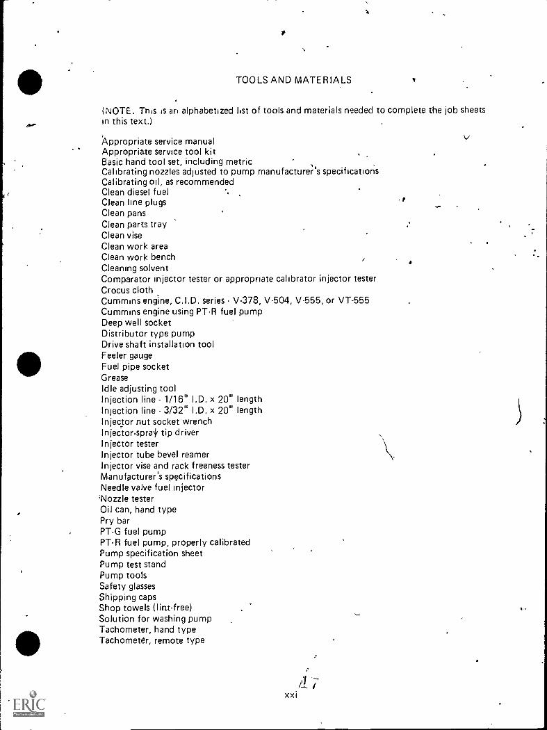
TOOLS AND MATERIALS
(NOTE. This is an alphabetized list of tools and materials needed to complete the job sheetsin this text.)
Appropriate service manualAppropriate service tool kitBasic hand tool set, including metricCalibrating nozzles adjusted to pump manufacturer s specificationsCalibrating oil, as recommendedClean diesel fuelClean line plugsClean pansClean parts trayClean viseClean work areaClean work benchCleaning solventComparator injector tester or appropriate cahbrator injector testerCrocus clothCummins engine, C.I.D. series V-378, V-504, V-555, or VT-555Cummins engine using PT-R fuel pumpDeep well socketDistributor type pumpDrive shaft installation toolFeeler gaugeFuel pipe socketGreaseIdle adjusting toolInjection line 1/16" I.D. x 20" lengthInjection line 3/32" I.D. x 20" lengthInjector nut socket wrenchInjector-sprai, tip driverInjector testerInjector tube bevel reamerInjector vise and rack freeness testerManufacturer's specificationsNeedle valve fuel injector'Nozzle testerOil can, hand typePry barPT-G fuel pumpPT-R fuel pump, properly calibratedPump specification sheetPump test standPump toolsSafety glassesShipping capsShop towels (lint-free)Solution for washing pumpTachometer, hand typeTachometer, remote type
a

,
0 t
-/41.
Telt stand adaptersTest stand manualTorque wrenchTorque wrench, inch-poundsTorque wrench, foot-poundsTypical tools as recommended by appropriate manufacturer
(NOTE: The tool numbers listed below are International Harvester.)
SE-2119--Rack gauge holder '.,.
SE-2121--Dial indi.cator (itch reading)SE-2339--Wrench, holding, drive flangeSE-2340--Remover, goverhor flyweight damper
ISE-2341--Holder, tappet_SE-2342--Gauge, camshaft protrusionSC-s2343-1-foldet, dial irSdicator '
.
SE-2344--Remover and installer, camshaft cylindrical ni-JtSE-2345--Remover and installer, tappetSE-2346--Remover and installer, barrel plunger ,
SE-2347--Wrench, tappet adjustingSE-2348--Wrench, governor spring adjustingSE-2349--Remover and installer, governor spring and adjusting screw$E-2351--Fixture, pump holding
-0.
,
"ftioN
-I 0
t
,
-
4
9
e

A
REFERENCES
(NOTE. This is an alphabetized list of references used in completing this text.)
Dagel, Jqn F. Diesel Engine Repair. New York: John Wiley and Sons, Inc., 1982.
Detroit Diesel Allison, Service Manual. Detroit. Division of General Motors Corporation,1974.
Foutes, William A. Diesel Engine Mechanics. Stillwater, OK. Mid-America VocationalCurriculum Consortium, 1977.
Fuel System. Fuel Injection Pump Robert Bosch "A" Type for 0 V-4628 2nd DV-550BEngines. Chicago: International Harvester Co.
Fundamentals of Service: Engines. Fifth Edition. Moline, IL. Deere and Company, 1980.
Kates, Edgar J., and Luck, William E. Diesel and High Compression Gas Engines. ThirdEdition.Chicago: American Technical Society, 1974.
Roberi. Bosch Corporation. Bulletin No. 221.1.03.. 4.131.A Directors Row, Houston, TX.
Roosa Master. Operation and Instructional Manual: Model DP Pump. Hartford, CT:Stanadyne/Hartford Division/Roosa Master.
Schulz, Erich J. Diesel Mechanics. New York. Gregg Division, Mctraw-Hill Book Company,1977
Service Bulletin No. 3379011-01: Injector Plunger and Valve Adjustments. Columbus,IN: CumminS Engine Company, Inc., December, 1975.
Service Bulletin No. 3379071-02. Injectors, All Types. Columbus, IN: Cummins EngineCompany, Inc., December, 1975.
Svrvice Bulletin No. 3379084-02: Fuel Pump PT Rebuilding. Columbus, IN: CumminsEngine Company, 1980.
Service Bulletin No. 3379101-00. PT Fuel Pump Calibration. Columbus, IN:: CumminsEngine Company, Inc., December, 1975.
Service Bulletin No. 983535. Fuel Pump PT Rebuilding. Columbus, IN. Cummins EngineCompany, Inc., 1975.
Servide Bulletin No. 983725: Calibration of PT-G Pumps. Columbus, IN. Cummins EngineCompany, Inc., 1975.
Service Arnual, Detri<Diesel Engines. Detroit: Detroit Diesel Allison, 1975.
Technical Manual: John Deere Fuel Injection Equipment Robert Bosch. Moline, I L:Deere and Company, April 1974.
.Toboldt, William K. Diesel. Fundamentals, Service, Repair. South Holland, IL: Goodheart-Willcox Company, Inc., 1980.

b
..
4
INTRODTION TO FUEL INJECTION SYSTEMSUNIT I_
UNIT OBJECTIVE
After completion of this unit, the student should be able to select major functions of a fuelinjecticm system and list methods of injecting fuel usipg a pump and injection nozzle. Thisknowledge will be evidenced by scoring 85 percent on the unit test.
4
SPECIFIC OBJECTIVES
After completion of this unit, the student should be able to:
1. Match terms related to fuel injection systems with thek correct definitions.
2; Select major functIons of a fuel injection system.
3. Name two types of fuel injection systems._
4. Complete a list of methods of injecting fuel using the pump and injectionnozzle.
5. Select true statements concerning facts about fuel injection systems.,
4 U
f
..
D:FS-1

o....!"...
INTRODUCTION TO FUEL INJECTION SYSTEMSUNIT I
N SUGGESTED ACTIVITIES
I. Provide student-with objective sheet.
II. Provide student with informati\sheet.
-.III. Discuss unit and specific objectiVes.
iV. Discuss.information sheet. 14
V. Make a display of the different types of fuel, injection systems.
VI. Demonstrate the spray patterns of various injectors._
VII. - Emphasize safety procedures to follow when working with fuel injectors.e
VIII. Take a field trip to a f'Dti injection shop.
IX. Give test.
INSTRUCTIONAL MATERIALS
D: FS-3
\
-
o ,
ft
..
I. Included in this unit:
A. Objective sheet
B. Information sheet
C. Test
D. Answers to test
II. References:
A. Kates, Edgar J. and Luck, William E. Diesel and High Compression GasEngines. Third Edition. Chicago: American Technical Society, 1974.
Il B. Schulz, Erich J. Diesel Mechanics. New York: Gregg Division, McGraw-HillBook Company, 1977.
Toboldt, William K. Diesel Fundamentals, Service, Repair. South Holland,IL: Goodheart-Willcox Company, Inc., 1980.
D. Dagel, John F. Diesel Engine Repair. New York: joh-n Wiley and Sons,Inc., 1982.
21
-

INTRODUCTION TO FUEL INJECTION SYSTEMSUNIT I
IN'FORMATION SHEET
I. Terms and definitions
4A. Injection-Methad of forcing fuel into a chamber for combustion-
B. Transfer pump-Mechanical device that brings fuel from the fuel tank to theinjection pump
C. Fuel injection pump--Times, measures, and delivers fuel under pressureto the injection nozzles
D. Ignition delay--Period of time from injection to actual ignition
E. Flash point-When fuel is heated to a point where it gives off a flammablevapor
F. Ignition-Combustion of fuel mixture in the combustion chamber
G. Cetane number--The rating of a diesel fuel's ignition
H. Atomize--Break down into small particles
I. Unit injector-Pump and fuel injection nozzle combined into one Ligi
J. Fuel injection nozzle--Atomizes and distributes fuel evenly into the cgmhus-tion chamber
II. Major functions of fuel injection system
A. Supplies Vie correct quantity offuel
B. Times the fuel delivery
C. controls the delivery rate
D. Atomizes the fuel
E. Distributes fuel evenly throughout the combustion chamber
I I I. Types of fuel injection systems
A. Common rail system
B. Jerk pump system
(NOTE: Almost all modern diesel systems are of this type.)
1. Unit injector
2. In-line

6
',LC'RMATION SHPF1
4 )1un 'bo'...t)f- try pe
!V Pump and inject,on ,iptnor4-, for injecting tuel1
tiome fi'E'-'Lt Uri nozzle f(y- each cylirider
!NOTE Som,, Pr4P,2 ,iump inanufacturers who use this system areAmerican Bosch, Br)si.n, C A V end Sims
B Combined pump and i'ilectio nozzle for each cylinder (unit injector type)
i%0TE Sorrtl engirib do;. p,ump neliutacturers who use this system areGeneral Motors Coroorat'ion and Cummins Eogine Company.)
C Pump in common frii-,usino, njection nozzle for each cylinder (in-line type)
(NOTE, Some eng ne and or ft.:mi.) manufacturers who use.this system areBosch, American Bosch, C.A V , Sims, and Caterpillar )
D Ore Rump serving njectinn nozzles for several cylinders (distributor type)
(NOTE Some e-g're aro, ci purnr; manufacturers who use this system areRoosa Master, American Bosch, Robert Bosch, C.A.V., and D.P.A.)
FacTs about fue' injection ,y.s',er"s
A The firs-t in)ecton S used air to force coal duv into the combustionchamber
B The first 'uei injector jsed air ro force fuel into the combustion chamber
C AIR IS.ALWAY`: COMPRESSED BEFORE FUEL IS INJECTED
0 Fuel ntist be ever !y distr,buten throuqnout the cylinder
E Ali fuel injectors are meGhanicall/ op,r d
F Fuel is iniec'nd high oressure-2500 3000 psi or more

INTRODUCTION TO FUEL INJECTION SYSTEMSUNIT I
NAME
TEST
1. Match the terms on the right with their correct definitions.
a. Method of forcing fuel into a chamber forcornbustion
b. Mechanical device that brings fuel fromthe fuel tank to the injection pump
c. Times, measures, and delivers fuel under,
pressure to the injection nozzles
d. Period of time from injection, to actual,,ignition
e. When fuel is heated to a point where it gives'off a flarnrnable vapor
16.
f. Combustion of fuel mixture in the cornbus:,tion chamber
g. The rating of a diesel fuel's ignition
h. Break down into small particles
i. Pump and fuel injection nozzle combinedinto one unit
j. Atomizes and distributes fuel evenly ,into thecombustion chamber
1. Atomize
2. injection
3. Fuel injectionpump
. Unit injector
5. Ignition
6. Cetane number'
7 Fuel injectionnozzle
8. Flash point
9. Ignition delay
10. Transfer pump
2. Select major functions of a fuel injection system by placing an "X" in the appropriateblanks.
a. Supplies the correct quantity of fuel
b. Pulls the fuel from the pump
c. Returns fuel to the filters
d. Atomizes the fuel
e. Distributes fuel evenly throughout the combustion chamber
D: FS-7

8
3. Name two 'types of fuel injection systems.- /
a.
b.
%
i
1) Unit injector
2) Inline
3) Multi-plunger in common housing
4) Single plunger, distributor type
-.,
VoZ,
4. Complete the following list of methods of injecting fuel using the pump and injectionnozzle. .
a. and injection nozzle for each cylinder
b. and injection' nozzle for each cylinder«
c. Pump in common housing, injection nozzle for each cylinder
d. serving injection nozzles for several cylinders
5. Select true statements concerning facts about fuel injection systems by placing an "X"in the appropriate blanks.
fD
a. The first injection systems used air to force coal dust into the combustionchamber
b. The first fuel injector used air to force fuel into the combustion chamber
c. AIR IS ALWAYS COMPRESSED BEFORE FUEL IS INJECTEDk
ti. Air must be evenly distributed throughout the combustion chamber
e. All fuel injectors are mechanically operated
f. Fuel is injected by very low pressure--1000-1500 psi or less
?
\
?, u
l
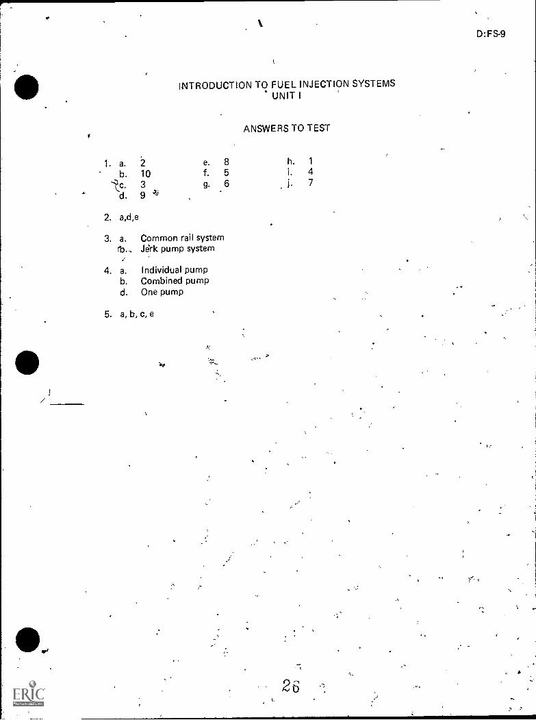
INTRODUCTION TO FUEL INJECTION SYSTEMSUNIT I
ANSWERS TO TEST
1. a. 2 e. 8 h. 1
b. 10 f. 5 i. 4
d.3 g.
96 j. 7
2. a,d,e
3. a. Common rail system13 Jerk pump system
4. a.
b.d.
Individual pumpCombined pumpOne pump
5. a, b, c, e
7".
D:FS-9

FUEL SYSTEM COMPONENTSUNIT II
UNIT OBJECTIVE
After completion of this unit, the student should be able to name the major parts of a fuelsystem end match the parts to their functions. The student should also be able to distin-guish between the operation of series and parallel dual filters. This knowledge will beevidenced by scoring 85 percent on the unit test.
SPECIF IC OBJECTIVES
After completion of this unit, the student should be able to:
1. Match terms related to fuel system components with their correct definitions.
2. Name six major parts of a.fuel system.
3. Match the parts of a fuel system with their functions.
4. Name threEfuel tank maintenance problems.
5. Match types of fuel lines with their purposes.
6. Select true statements concerning the purpose of a fuel transfer pumP..
7. Name three types of filters used during stages of fuel filtration on-a typical dieselfuel,system.
8. Complete a list of staternents concerning fuel filters and separators.
9. Distinguish between the operation of series and parallel dual filter's.
D: PS-11
'

FUEL-SYSTEM COMPONENTSUNIT II
SUGGESTED ACTIVITIES
I. Provide student with objective sheet.
II. Provide student with information sheet.
III. Make transparencies.
IV. Discuss unit and specific objectives.
V. Discuss informetim sheet.
VI. Show students different high pressure lines.'
VII. Demonstrate safety precautions on high pressure lines.
VIII. Have a display of different types of filters.
IX. Give test.
INSTRUCTIONAL MATERIALS
I. Included in this unit:
A. Objective sheet
B. Information sheet
C. transparency masters
1. TM 1--Fuel System Components
6
2. TM 2--Detroit Diesel Fuel System and Final Filter on Fuel Injector
3. TM 3--Types of Fuel Lines
4. TM 4--Stages of Fuel Filtration
5. TM 5--Water Separetor and primary Filter
6. TM 6--Agglomerator Filter
7. TM 7--Spin-On Fuel Filter
8. TM 8--Series Dual Fuel Filters
D. Test
E. Answers to test
28"
D:FS-13

14
II. References:
A. Fundamentals of Service: Engines. Fifth Edition. Moline, IL: Deere andCompany, 1980.
B. Kates, Edgar J. and Luck, William E. Dieser and High Compression GasEngines. Third Edition. Chicago: American Technical Society, 1974.
C. Detroit Diesel Allison: Service Manual. Detroit, MI: Division of GeneralMotors Corporation, 1974.
D. Dagel, John F. Diesel Engine Repair .New York: John Wiley and Sons,Inc., 1982.

\
,
FUEL SYSTEM COMPONENTSUNIT H
INFORMATION SHE.ET
v
I. Terms and definitions
A. Fuel lines--High and low pressure tubes that connect the fuel system
B. Primary filterFilters out initial impurities
C. Secondary filter--The second filter in a fuel system; it has a finer filteringcapacity
D. Final filterUsed as a safety factor, if coHects anything that escapes otherfilters
E. Micron--A unit of measurement that is used to rate the efficiency of filters;one micron equals one millionth of a meter or 0.000039 inch
F. Fuel transfer pump--Moves fuel from fuel tank to fuel pump
G. Water separator--A cup or bowl usually at the bottom of the fuel filter. thatallows the heavier water to settle to the bottom to be drained off
H. Major parts of fuel system (Transparencies 1 and 2)
A. Fuel tank
B. Fuel transfer pump
C. Fuel filter
D. Fuel injection pump .
E. Unit injector
F. Fuel injection nozzle
' HI. Fuhctions of fuel system parts (Transparency 1')
A. Fuel tank--Stores fuel
B. Fuel filter--Cleans the fuel
C. Fuel transfer pumpSupplies fuel to injection pump at low pressure
D. Fuel injection pumpTimes, mea§ures, and delivers fuel under pressureto injection nozzles
E. Fuel injection nozzleAtomizes and distributes fuel evenly into combustionchamber
F. Unit injectorPerforms functions of *both the injection Pimp and nozzleastme unit
,
vo
.
D:FS-15
AP
,a
16
INFORMATION SHEET
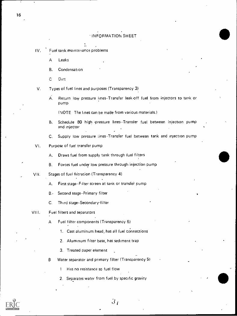
IV. Fuel tank maintenance problems
A Leaks
B. Condensation
Dirt
V. Types of fuel lines and purposes (Transparency 3)
A. Return low pressure lines-Transfer leak-off fuel from injectors to tank orpump
(NOTE The lines can be made from various materials.)
B. Schedule 80 high 'pressure hnes--Transfer fuel between injection pumpand injector
C. Supply low pressure lines--Transfer fuel between tank and injection pump
VI. Purpose of fuel transfer pump
A. Draws fuel from supply tank through fuel filters
B. Forces fuel under low pressure through injection pump
VII. Stages of fuel filtration (Transparency 4)
A. First stage-Filter screen at tank or transfei- pump
B. Second stage--Primary filter
C. Third stage-Secondary-filter
VIII. Fuel filters and separators
A Fuel filter components (Transparency 6)
1. Cast aluminum head, has all fuel cOnnections
2. Aluminum filter base, has sediment trap
3. Treated paper element
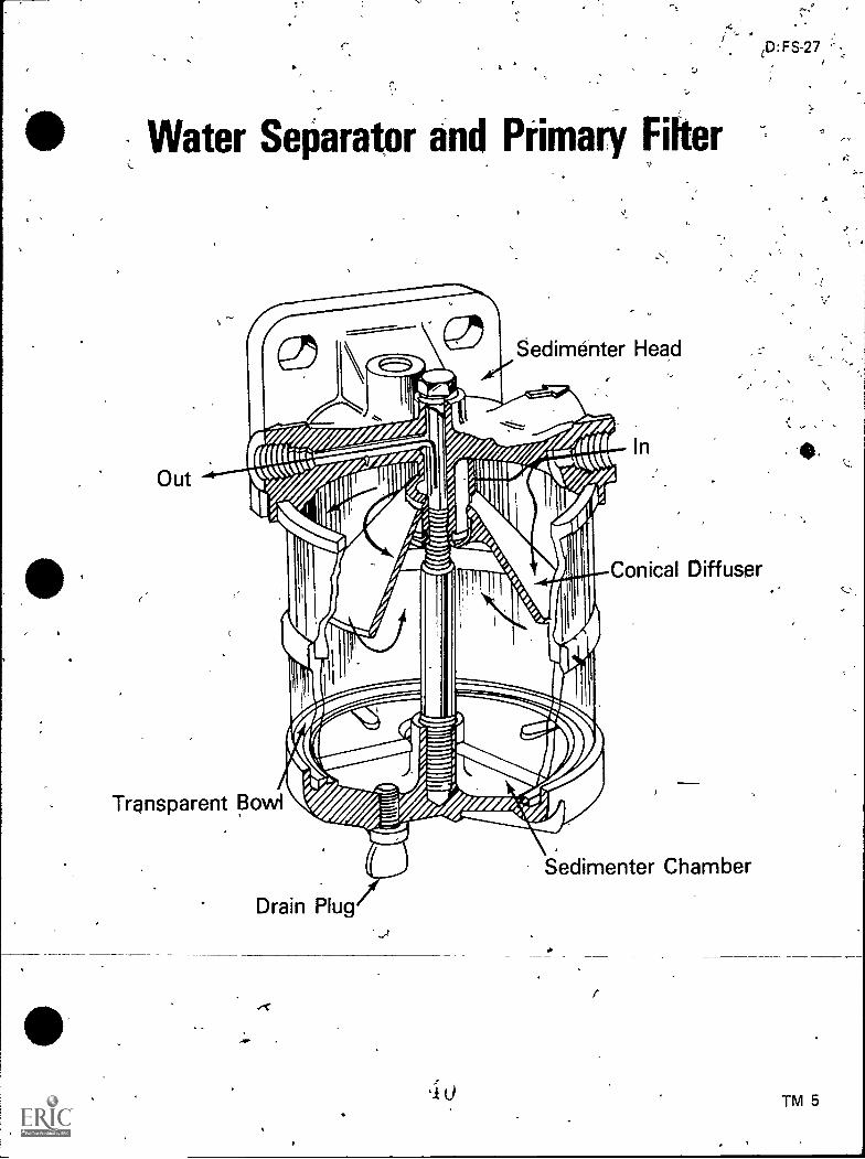
B Water separator and primary filter (Transparency 5)
1 Has no resistance to fuel flow
2. Separates water from fuel by specific gravity
414
INFORMATION SHEET
3. Has no moving parts
4. Is effective in freezing or waxing conditions
5. Can be drained c;f sediments
6. Mounted on suction side of the pump .
C. Agglomerator filter (Transparency 6)
1. Uses single bolt for filter change/."
2. Water drains without dismantling
3. Fuel flows in the inlet and through the paper filter where it separatesthe impurities
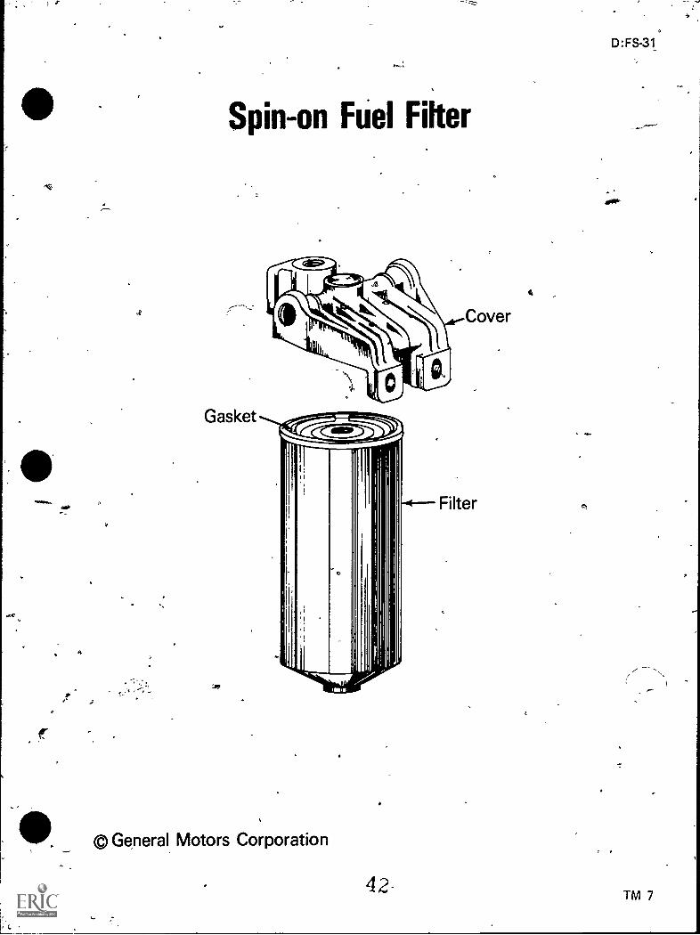
D. Spin-on filter (Transparency 7)
1. Gasket is part of the filter
2. Easy to change for more serviceability
3. Has no resistance to fuel flow
4. Fuel flows in the inlet and through the paper filter where it separatesthe impurities
Operati-o-n'of rfUal-firfer§' (Trar*56-ren6i-ar---
D:FS-17
A. Series-All fuel flows through one filter before flowing through the other
B. Parallel--Parif the fuel goes through each filter

..
0
CombustioniChamber I
4
z.
T.
Fuel System Components
Injection Nozzlesy
4-
. Injection Pump(Distributor Type)
Fuel\, k
Fuel FiltersTransfer Pump 0
,
g cn
_. 3 3 3 4 (.-8
4)
,
,

'A
7,-...
0 Detroit Diesel Fuel System and FinalFilter on Fuel Injector
Fuel Pipes
i--I- -_: - 1
=-----7
Fuel Injector \i Restricted FittingCheck Valvei Fuel Pump
%,-....Erm....... Fuel Filter
.-:
Out
Fuel Strainer-0-
D:FS-21
Fuel TankN./
System Fuel Flow
Filter 6p-0-
Gasket
Final Filter..
Injector Body--1.-
.,
.Location of Final Filter on Fuel Injector
© General Motors Corporation
30
a
&.-
TM 2

o e
%
3 t3
Types of Fuel Lines
Noale Leak-Off Lines
-
,
Fuel ReturnLine
Very High Pressure
Fuel
Injection
Lines
-Fuel Supply Lille
Low PressweI
,
e
,,
No Pressure
,
3 i

,
*Stages of Fuel Filtration
.,
Filter Bo WI
Secondary Filter Primary Filter D rt Filter Screen
),
0I Li,
g 3 0cp
it. CA
3 3 .
-,
u
,....N
. .
ID:FS-27,
Water Separator and Primary Fitter
Out
,.,
-
8edimenter Head
Transparent Bowi
Drain Plug,I
..,
,
0.
Conical Diffuser
Sedimenter Chamber
r
TM 5

V
(
-
) 1
A
)..2
)'
Agglomerator Filter
)
Filter Agglomerator Head)
FilterPaperElement
TransparentBowl )
77
)'
,))
,1
D:FS-29
Sed imenter,ChaMber'
)
"'
TM 6
) )
-
Spin-on Fuel Filter
Gasket
6
General Motors Corporation
42
D:FS-31
TM 7

4),
43
, (
Series Dual Fuel Filters
Air Bleed Screws
i
Fuel Inlet
3
Cotton String
Element-
First Stage
Paper Element-
Second Stage
\SedimentBowls
Drain Screws,
..
,.
FUEL SYSTEM COMPONENTSUNIT II
NAME
TEST
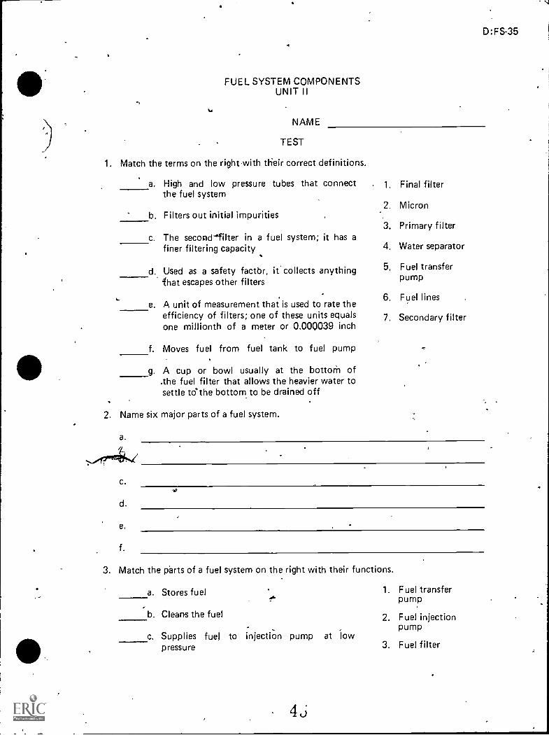
1. Match the terms on the right-with their correct definitions.
a. High and low pressure tubes that connect 1. Final filterthe fuel system
b. Filters out initial impurities2. Micron
c. The seconefilter in a fuel system; it has a3.
4.
Primary filter
Water separatorfiner filtering capacity
d. Used as a safety factbr, it' collects anything 5. Fuel transferpumplhat escapes other filters
e. A unit of measurement that is used to rate the6. Fuel lines
efficiency of filters; one of these units equalsone millionth of a meter or 0.000039 inch
f. Moves fuel from fuel tank to fuel pump
7. Secondary filter
g. A cup or bowl usually at the bottorh of.the fuel filter that allows the heavier water tosettle to-the bottom to be drained off
2. Name six major parts of a fuel system.
a.
c.
d.
e.
f.
3. Match the parts of a fuel system on the right with their functions.
a. Stores fuel
-b. Cleans the fuel
c. Supplies fuel topressure
injection pump at iow
4j
1. Fuel transferpump
2. Fuel injectionpump
3. Fuel filter
D:FS-35

10.
36
#
,
d. Times, measures, and deliver§ feel underpressure to injection nozzles
e. Atomizes and distributes fuel evenly intocombustion chamber
f. Performs functions of both the injectionpump and nozzle as one unit
4., Name.three fuel-tank maintenance problems.
a.
b..
C.
4. Fuel tank
5. Unit injector
6. Fuel injectionnozzle
5. Match types of fuel lines on the right with their purposes.
a. Transfer leakoff fuel from injectors totank or pump
b. Transfer fuel between injeotion pump andinjector
c. Transfer fuel between tank and injectionpump
1. Supply lowpressure lines
2. Return lowpressure lines
3. Schedule 80 highpressure lines
6. Select true statements concerning the purpose of a fuel transfer pump by r5lacingan "X" in the appropriate blanks.
a. Draws fuel from supply tank through Nal filters
b. Forces fuel under high pressure through injection pump
7. Name three types of filters used during stages of fuel filtration on a typical diesel fuelsystem.
a. First stage--
b. Second stage--
c. Third stage--..
8. Complete the following list of statements concerning fuel filters and separators.
i
a. Fuel-filter components
1) Cast aluminum head, has all fuel connections
2) Aluminum filter base, has
3) Treated paper element,
,
,
b. Water separator and primary filter
1) Has no resistance to fuel flow
2) Separates water from fuel by
3) Has no moving parts
4
4) Is effective in freezing or conditiOns
5) Can be drained of sediments
6) Mounted on suction iide of the pump
c. Agglomerator filter
1) Uses single bolt
2) pater drains without dismantling
3) Fuel 'flows in the inlet and through the paper filter where it separates theimpurities
d. Spin-on filter
1) Gasket is part of the filter
2) for more serviceability
3) Has no resistance to fuel flow
4) Fuel flows in the inlet apd through the paper filter where it separates theimpurities
9. Distinguish between the operation of series and parallel dual filters by placing annext to the description of series filters.
a. All fuel flows through one filter before flowing through the other
b. Part of the fuel goes through each filter
4 7
D:FS-37
..

*
l
,
,
FUEL SYSTEM COMPONENTS .
UNIT II
ANSWERS TO TEST
637
1
e.
f.g.
2
54'
0
2. a. Fuel tankb. Fuel transfer pumpc. Fuel filterd. Fuel.injeciion pumpe. Unit injectorf. Fuel injection nozzle
3. 'a. 4- b. 3I C. 1
d. 2
e. 6f. 5
4. a. Leaks
b. Condensationi c. Dirt
5. a. 2b. 3C. 1
6. a
,
7. 'a. Filter screen at tank or transfer pumpb. Primary filterc. Secondary filter ,
8, a. 2) Sediment trapb. 2) Specific gravity
4) Waxing-c. 1) for filter changed. 2) Easy to change
9. a
4 3
-
.%
D:FS-39
,

b:FS-41
DISTRIBUTOR TYPE INJECTION PUMPUNIT m
UNIT OBJECTIVE
After completion of this unit, the student should be able to identify the main parts of adistributor type pump and arrange in order the steps in which fuel flows during a completepump cycle on a distributor type pump. The student should also be*able to remove, benchtest, and install a distributor type pump. This Ilcnowledge will be evidenced by corredtlyperforming the procedures outlined in the job sheets and by scoring 85 percent on the unittest.
SPECIFIC OBJECTIVES
After completion of this unit, the student should be able to:
1. Match terms related to a distributor type injection pump with their correctdefinitions.
2. Identify-the main parts of a distributor type pump.
3. Name three rotating parts of a distributor type pump.
4. Match the main parts of a.distributor type pump with their functions.
5. Select true statements concerning the principles of operation of a distributor typepump.
6. Arrange in order the steps in which fuel flows during a complete pump cycleon a distributor type pump.
7. Select true sta*ments concerning charging cycle operation.
8. Complete a list of statements concerning discharge cycle operation.
9. Select true statements concerning delivery valve operation.
10. Select true statements concerning return fuel oil circuit functions.
11. Name three functions of an end plate.
12.. Complete a list of optional features of a distributor type pump.
13. Demonstrate the ability to:
a. Remove a distributor type pump from an engine.
b. Bench test a distributor type pump.
c. Install a distributor type pump on an engine.
49

DISTRIBUTOR TYPE INJECTION PUMPUNIT III
SUGGEfiED ACTIVITIES
I. Provide student with objective sheet.
II. 'Provide student with.information and job sheets.
III. , Make transparencies.
IV. Discuss unit and specific objectives.
V. Discuss information sheet.
VI. Demonstrate and discuss the procedures outlined in the job sheets.
VI I. , Inform students this unit is written on a Roosa Master DP injection pump.
VI II. Color code fuel oil passages on transparency masters.
IX. Discuss disassgmbly of an injection pump.
X. Have students look up calibration data for an injection pump to use when bench
testing.
Xl. Take a field trip to an injection lab.
XI I. Give teit.
INSTRUCTIONAL MATERIALS
incIAed in this unit:
A. Objective sheet
B. Information sheet
C. Transparency masters
1. TM 1--Main Parts of Distributor Type Pump
2. TM 2-*-Fuel FloW
3. TM 3Delivery Valve Operation
4. TM 4End Plate Assembly with Transfer Pump
5. TM 5. Optional Features of a Distributor Type Pump
6. TM 6--Optional Features of a Distributor Type Pump (Continued)
0
D:FS-43

44
D. Job sheets
1.. Job Sheet #1--Remove a Distributor Type Pump from an Engine
2. Job Sheet #2--Bench Test a Distributor Type Pump
3. Job Sheet #3--Instill DistributonType Pump on an Engine
E. Test
F. Answers to test
I I. References-.
A. Toboldt, William K. DieselFundamentals, Service, Repair. South Holland,IL: Goodheart- Willcox Company, Inc., 1980.
B. Kates, Edgar J., and Luck, William E. Diesel and High Compression GasEngines. Third Edition. Chicago: American Technical Society, 1974.
C. Fundamentals of Service: Engines. Fifth Edition. Moline, I L: Deere andCompany, 1980.
D. Roosa Master: Operation and Instructional Manual: Model DP Pump. Hart-ford, QT: Stanadyne/Hartford Division/Roosa Master.
E. Dagel, John F. Diesel Engine Repair. New York: John Wiley and Sons,Inc., 1982.
F. Foutes, William A. Diesel Engine Mechanics. Stillwater, OK Mid-AmericaVocational Curriculum Consortium, 1977.

DISTRIBUTOR TYPE INJECTION PUMPUNIT III
INFORMATION SHEET
I. Terms and definitions
A. Distributor type ict4 system-Normally uses one pump to distributefuel to all cylinder
B. Annulus--Ring; a part, structure, or marking resembling a ring
C. Hydraulic--Operated or moved by liquid in motion
D. Registry--Oil passage that indexes vvith a port in a rotating head
E. Metering--Precision measurement of fuel,delivery
F. Retraction-Act of drawing back
G. Servomechanism--Automatic device for controlling large amounts of powerwith small amounts of power is a piston moved by fluid under pressure
H. Circuit--Complete path of fuel flow
I. Delivery valve--Provides retraction of delivery line pressure causing nozzlevalve to return to its seat, preventing dribble of fuel into combustion cham-ber
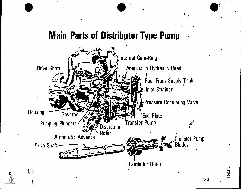
Main parts of distributor type pump (Transparency 1) , 4
A. Drive shaft
B. Distributor rotor
C. Transfer pump
D. Pumping plungers
E. Internarcam-ring
F. Annulus in hydraulic head
G. End plate
H. Governor
I. Automatic advance
J. Housing
,4
D:FS-45

46
al head to injection nozzles
,,
INFORMATION SHEET1
III. Rotating parts of distributor type pump (Transparency 1)
A. Drive shaft
B. Distributor rotor
C. Transfer pump blades
IV. Functions of main parts (Transparency 1)
A. Drive shaft--Turns distributor rot& in the hydraulic head
B. Distributor rotor--Rotation of rotor causes pumping action of plungerswhich discharge fuel when passages index with appropriate passages' inthe hydraulic head
- '
,C. Transfer pumpDraws fuel from supply tank through inlet strainer to
pump
(NOTE: Vane type pump is attached to opposite end of distributor rotor.)
D. Pumping plungers--Provide pressure to transfer fuel from rotor to hydraulic
L
E. Internal cam-ringActuates the pumping plungers
F. Hydraulic head--Contains the metering valve and the pore in whidh therotor revolves ,
G. End plate--Houses the transfer pump pressure regulating valve and fueli stra in er
..,
H. Governor--Regulates the sr:reed by positive mechanical linkage to meteringvalve
,
I. Automatic speed advance--Hydraulic servomechanism powered by oil pres-sure from the transfer pump which advances injection timing
(NOTE: Not all pumps are equipped with an automatic speed advance.),.,
J. HousingContains all component parts .
V. Principles of operation of distributor type pump, (Transparency 1)
A. Drive shaft engages the distributor rotor in the hydraulic head
(NOTE: Drive end of rotor has two cylinder bores, each containing twoplungers.)
B. Plungers are adtuated toward each othei simultaneously by the internalcam-ring to pump fuel
C. As rotor revolves inside hydraulic head, the discharge passage in the rotorindexes with appropriate passage in the hydraulic head to lead to the injectornozzles

D:FS-47
I4ORMAT ION SHEET
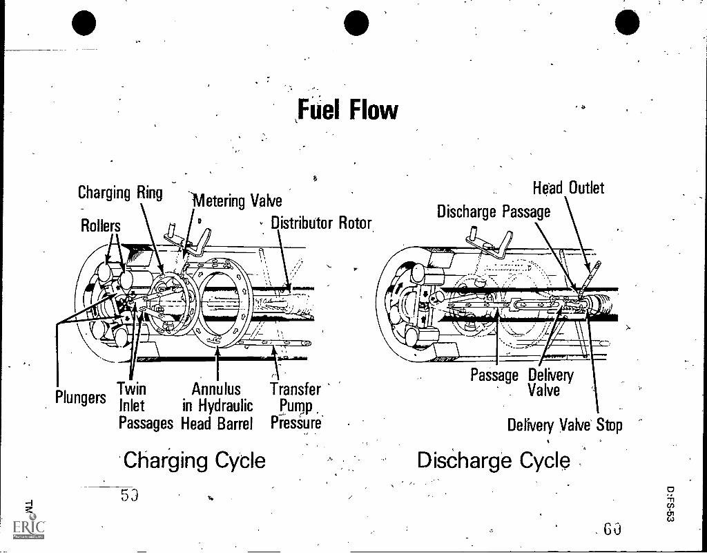
, VI. Fuel flow (Transparency 2)
A. Fuel is drawn from the supply tank into the pump through the inlet strainerby the vane type fuel transfer pump
B. Transfer pump pressure forces fuel through drilled passages in the hydraulichead into the annulus
C. Transfer pump pressure increases with speed
D. Fuel flows around the annulus to top of sleeve and through connecting,passages to metering valve
E. Metering valve regulates the flow of fuel into the charging' ring which incor-porates the charging ports
F. As the,rotor revolves, the twin inlet passages register with two charging portsin the hydraulic head allowing fuel to flow into the pumping cylinders
G. With further rotation, the inlet passages move oRt of registry and the singledischarge port is opened
H. The rollers contact the cam lobes forcing the plungers together
I. Fuel trapped between the plungers is then delivered through delivery valve tothe nozzle
VII. Charging cycle operation (Transparency 2)
A. When the rotor revolves, the angled inlet passages in the rotor line up withthe charging ports qf the dharging ring
B. Pressurized fuel from the transfer pump, controlled by the opening of themetering, valve, flows tO the pumping cylinders forcing all plungers apart
C. The plungers move outward enough to supply the correct quantity offuel for the engine load
(NOTE: 'At idle the plungers would move Very little, whereas at maximumload they would go into full fuel positioh.)
VIII. Discharge cycle operation (Transparency 2)
A. As the rotor continues to revolve, the angled inlet passages no longer line upwith the charging ports
B. 'Fuel is momentarily trapped until the rotor discharge passage lines upwith one of the head outlets
C. The rollers contact the cam lobes and are forced together

48
INF-ORMATION SHE-ET
D. -ruel is then for'ced throUgh the:dxial passage of the rotor, then to the-injection line .
_..,.
E. Delivery of the fuel will continue until the rotors pass the high Point on the.cam
. .
F. The fuel pressure in the .#xial passage is then reduced to a point wherethe injection näzzle closes
Delivery valve operation (Tr-ansparendy 3)
-. A. Controlled -1,,ine retraction is. the most important job of the delivery valve;thrs is accomplished by reducing injection line pressure to a point lower thanthat of the nozzle closing-pressdre
B. The delivery valve is located in a drilled passageway in the center of therrotor
C. There is only' one delivery valve, so all cut-off points will be the same
D. As injection begins, fuel pressure moves the delivery valve off its shoulder toallow the volume of its diSplacement to enter the cavity that houses thedelivery v.aliie Spring
E. This displaces a similar v olume of fuel in the spring cavity before.delivesystens through_the valve ports
F. At the end of .injection, the pressure on the plunger side of the delivery valveis reduced, allowing the cam rollers to fall into the' retrktion step of the cam -
lobes
,
G. As the valve moves back, the fuel is removed from the spring ca vity andflows through the rotor discharge port; then, as the "rotor revolves, it is
trapped
X. Return fuel oil circuit functions
A. Transfer pump pressure is discharged into a caiity in the hydraulic head
B. The upper part of this ca-iity has a vent passage connected to,it
- s
CT Should air enter trhe t(ansfer pUrnii, it will be bled off and retdmed to thefdel tank
f
Xl. Functions of end plate (Transparency 4)
A. Provides fuel inlet passages and houses pressure reguratingnvalve
-43. Covers the fuel transfer pump
C. Absorbs end thrust of drive and govemor

.-INFORMATION SHEET
XI I, Optional featuresf distributor type pump (Transparencies 5 and 6)
A. Viscosity compensator
,
B. Centrifugal governor
C. Automatic load advance
D. AutorTic speed advance
E. Torque control
F. Electric shot-off
4001000.0.4.-
4:t
0
t..
_
D:FS-49
4
,
VI
4),
a
Main Parts of DistriNitor Type Pumi)
Internal Cam-Ring-
Annulus in Hydraulic HeadDrive Shaft-
Housing ------ Governor
Pumping PlungersDistributor
Automatic Advance\-Rofor
Drive Shaft -----N.
Fuel From Supply Tanki
Inlet _Strainer
Pressure Regulating Valve
End Plate
Transfer Pump
1 MB
til Transfer PumpA?
litl., Bladesak
Distributor Rotor
5758
0lhcnen
Fuel Flow
Charging Ring --meteringValve
Rollers Distributor Rotor,
,
Twin Annulus TransferPlungers
Inlet in Hydraulic Purrip
Passages Head Barrel Pres'Sure
Charging Cycle
53
He'ad Outlet
Discharge Passage
1/41
Passage DeliveryValve
Delivery Valve Stop
DisChargé Cycle
6 -0
I.

*
Cylinder's
1
,,-
io
Delivery Valve Operation
Roller Discharge Passage
Head Outlet
..
k-si-"411111V. 4firi"tiirlip Awl. ....___
Rollers
Passage
,
Delivery Valve
Delivery Valve Spring
Delivery Valve Stop

"A"
Regulating
Spring
TransferPump
Blades
End Plate Assembly with Transfer Pump
Inlet Screen
Adjusting Plug
Pressure Regulating
Sleeve
Regulating Piston
Piston SealTransferPumpLiner
End Plate
Orifice
Pressure Regulating Valve

t
Optional Features of a Distributor Type Pump
Low IdleSging
Linkage Hook
GovernorSpring
Governor Arm
Pivot Shaft
-77-Thrust -.(4-i--Sleeve -:------"'
Throttle Shaft
L).Metering Valve
s:
FlyweightWeightRetainer
6 j
Centrifugal Governor
..
Electrical Shut-Offt
_A
66

Optional Features of a Distributor Type Pump(Continued)
7*Automatic Advance
Mechanism
Pump Cam
Advance Pin
. Spring
67
.,
Piston
\Advance Trinirner Screw
Torque Control Screw
TorqueScrew
AutomaticSpeed Advance .
Trimmer Screw
,
63

,
DISTRIBUTOR TYPE INJECTION pUMPUNIT III
JOB SHEET #1--REMOVE A -DISTRIBUTOR TYPE PUMP FROM AN ENGINE
1. Tools and materials,
Distributor type pump
B. Appropriate service manual
C. Hand tool set
D. Solution for washing pump
E. Shop towels (lint-free)
F. Shipping caps or plugs for disconnected lines
G. Safety glasses
II. Procedure
D: FS-63
(CAUTION: Follow all shop safety procedures.)
(NOTE: Refer to engine manual and determine type pum installation. If driveshaft is part of engine drive assembly, it remains with the e gine.)
A. Clean and wash down pump, fittings, and all Onnections to be brokento eliminate any chance of dirt entering the sy/stem when lines are discon-nected
/-
(CAUTION: All openings should be tennpoxparily plugged as linqi are discon-nected.)
B. Check the engine manual for proper tirhing position of crankshaft
C. Bar the engine in correct direction of rotation until the engine timing mark isindexed and the no. 1 cylinder is on compression stroke
D. Remove the timing window cover frorn the outboard side of the pump
(NOTE: The timing Ilne on the governor weight retainer hub should bedirectly opposite the lipe on the cam. Engine performance will be poorif these lines are not indexed properly.)
(NOTE: To record static timing, remove no. 1 injector line from no. 1
injector and rotate engine slowly in direction of Jotation; when a drop,of fuel comes out of line, check timing mark and see if it is within specifica-tion.)
E. Disconnect the fuel supply, return, and nozzle leak-Off lines and all highpressure line& plugging all openings

64
, JOB SHEET #1
F. Disconnect throttle and shut-off linkage
G. Tie throttle lever in full fuel bosltion
H. Remove mounting nuts on the pump flange
I. Slide pump gently*from location
(CAUTION: 6ecareful..not to damage the pilot tube by cocking' puMp onremoval.)
7.
$
..
,

DISTRIBUTOR TYPE INJECTION PUMPUNIT III
JOB SHEET #2BENCH TEST A DISTRIBUTOR TYPE PUMP
I. Tools and materials
A: Distributor type pump
B. Appropriate,seryice manual
C. Hand toof.set
D. Injection line 1/16" I.D. x 20" length -
E. Injection line - 3/32" I.D. x 20" length
F. Calibrating nozzles adjusted to pump manufacturer's specifications
G. Pump test stand
H. Adapters--pump to test stand
I. Recommended calibrating oil
J. Shop towels, flint-free)
K: Safety grasses
,
4
-.3
D:FS-65

,
,
66
.,
,-i ' £s
JOB SHEET 1;2
II. Procedure
(CAUTION: Follow all 'shop safety procedures )
A. Cahbrate and test
1. Mount the pump securely with appropriate adapters
(NOTE: If pump employs a steel pilot tube, do not support the driveshaft in the housing. A drive adapter, usually with a ball bearing,supports the shaft. These pumps must be tested using an intermediatesupport bearing. See Figure 1.)
FIGURE 1
Bearing Mounting
2.
,
\To Pressure Gauge
2. Install high pressure injection lines using new gaskets
(NOTE Install two .new gaskets, one on each side of fitting. Leavefuel line connector screws at pump and injection line nuts at nozzlesloose.)
-3 Install inlet and return lines and transfer pump pressure gauge
(NOTE: Use a restriction fitting on the return line if the pump nor-mally uses one.)
4. Determine proper direction of rotation from pump name plate ("C"--Clockwrse, "Ct" -Counter clockwise)
(NOTE: Rotation is determinedas viewed from drive end of pump.)
5. -Start stand at,:lowest speed, and move throttle to "full-load" position/2
6. AH,ow fuel to bleed for several seconds from loosened connectorscrews when transfer pump picks up suction
/

(.2
D:FS-67
JOB SHEET #2
=_
7. Allow fuel to bleed from loosened injection line nuts; then, tightensecurely
(NOTE: If pump is factory tested on stands which measure fuel flowin cubic millimeters, it is necessary to convert the readings on othertypes of stands which measure in cubic centimeters. See Figure 2.)
FIGURE 2
00....y
s....6,...., c 0 0
:6,.Y ^ Cub< .Ilone,,s 114413, p.
2D I 100 125 200 250 8:0 402 500 103)
60 8 5 4 3.3 2.5 2 1 (31
2t
30 20 4 0 S 6 7 5 0 A 2
3 120 X 24 0 10 10 0 7 5 6 3
A
I160 60 32 20 6 3 3 10 0 8 A
5 200 , 50 40 25 20 16 7 I2.5 10 5
6 260 60 48 X 24 20 0 15.0 12 6
7 70 56 35 83 23.3 17.5 IA 7
I 320 80 64 60 32 26 7 20 .0 16 8
1 340 10 72 45 16 80.0 22.5 18 1
10 400 ICO SO 50 40 33.3 25.0 20 I0
20 200 140 103 ND 66.7 50 .0 40 20
X XO 240 150 170 132 0 75.0 410 30
60 400 320 830 40 133.3 100 .0
50 POO 250 ?CO 166.7 125.0 100 50
40 XO 240 200.0 150.0 1 20 40
70 150 20 233.3 I 75 .0 140 70
so...-
co 320 246.7 300.0 IN) 10
340 883.0 225.0 IND 00
132.. ICO 113.3 233.0 203 oa
(NOTE: The test stand tachometer registers pump speed. Some specifi-cation test data refers to engine speed.)
8. Operate pump at 1000 rpm for 10 minutes
9. Dry off completely with compressed airI
10. Observe for leaks and correct as necessary
11. Back out the high idle stop screw and torque screw (if equipped)
(NOTE: The inlet to the transfer pump should never be pressurizedduring bench testing.)
,J

68
JOB SHEET #2
12. Close valve in supply line
(NOTE: Check to see that transfer pump pulls up to manufacturersspecifications. If it does not, check for-air leaks on suction side ormalfunction of end plate and transfer pump parts. If the pump isequipped with an external by-pass,, it should be pinched off during thistest.)
13. Fill graduates to bleed air from test stand and to wet glass
14. Observe return oil
(NOTE: Compare observable return with manufacturer's specifications.By-pass equipped pumps will return less fuel.)
15. Operate the specified speeds with wide open throttle and observetransfe? pump pressure
(NOTE: Adjust pressure regulating spring plug to raise or lower transferpump pressure.)
(CAUTION: Under no circumstances should 130 psi be exceeded.See Figure 3.)
FIGURE 3
4
(PC' Y.'.
TRANar ER PUMP PRESSURE ADJUSTMENT
16. Check for minimum delivery at cranking speed
JOB SHEET #2
it
D:FS-69
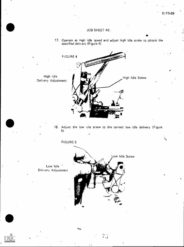
17. Operate at high idle speed and adjust high idle scre'w to _obtain thespecified delivery (Figure 4)
FIGURE 4
High IdleDelivery Adjustment
A
High Idle Screw
18. Adjust the low idle screw to the correct low idle delivery (Figure5)
FIGURE 5
-..,
Low IdleDelivery Adjustment
Low Idle Screw
i ij
v
.
70
JOB SHEET #2
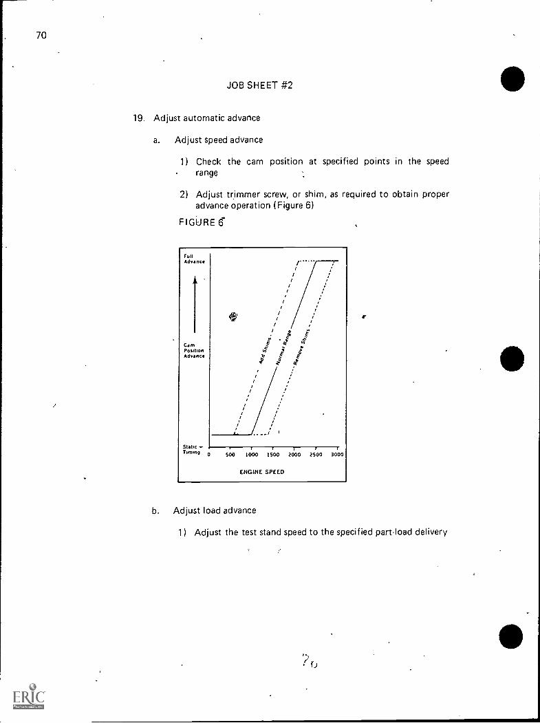
19. Adjust automatic advance
a. Adjust speed advance
1) Check the cam position at specified points in the speed. range
2) Adjust trimmer screw, or shim, as required to obtain properadvance operation (Figure 6)
FIGURE 6".
runAdvance
ICamPositionAdvance
StaticTumng 0
//
//
//
//
500 1000 1500 2000 2500 3000
ENGINE SPEED
b. Adjust load advance
r
1) Adjust the test stand speed to the specified part-load delivery
'i, 0

D:FS-71
FIGURE 7
Load Advance
Adjustment
FIGURE 8
JOB SHEET #2
2) Observe cam position and adjust guide stud for correctcam movement (Figures 7 and 8)
OUT Retard IN Advance
Port FromTransferPump
ToAdvanceMechanism
EFFECT OF LOAD ADVANCE ADJUSTMENT
20. Record fuel delivery at check points shown on the pump speCification
(NOTE: ROLLER SETTINGS SHOULD NOT BE READJUSTED ONTHE TEST BENCH. Experience has proven that micrometer and dialindicator settings provide more consistent, accurate results in perform-ance. Variations In test benches, nozzles, lines, and 'fuels in differentareas sometime result in inaccurate flow readings.).

72
r
JOB SHEET #2 ,
21. Set torque screw (if employed) to specified delivery while operating atfull-load governed speed (Figure 9)
, FIGURE 9
TORQUE SCREW ADJUSTMENT
, 22. Recheck delivery at lowest speed checkpoint
23. Check governor cutoff at specified speed
.., B. Remove from test stand and assemble all sealing wires; pump is now readyfor installation to engine
(NOTE: If there is no drive shaft with the pump, wire the throttle level
in "full fuel" position for shipment or until installed on engine. Otherwise,
mount the pump on drive adapter with shaft. Check shaft seals with apressure test on the housing.)
s 1
V1'
4)
I
DISTRIBUTOR TYPE INJECTION PUMPUNIT III
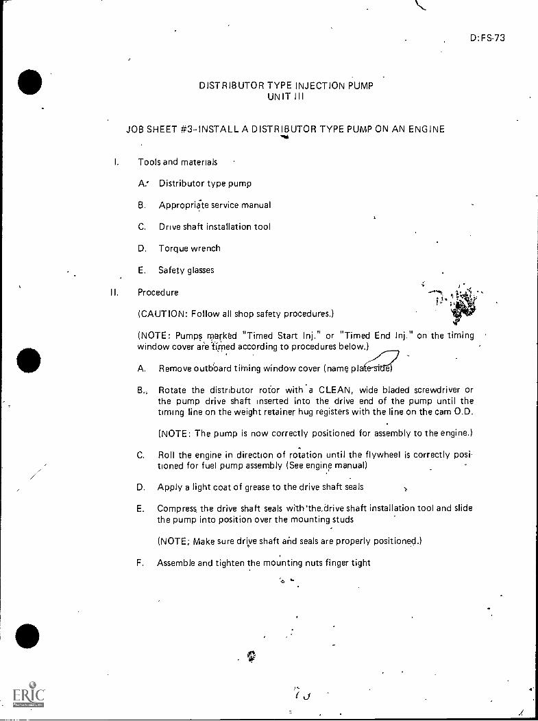
JOB SHEET #3-INSTALL A DISTRIBUTOR TYPE PUMP ON AN ENGINEwat
I. Tools and materials
A. Distributor type pump
B. Appropriite service manual
C. Drive shaft installation tool
D. Torque wrench
E. Safety glasses
II. Procedure
(CAUTION: Follow all shop safety procedures.)
D:FS-73
(NOTE: Pumps rparkd "Timed Start Inj." or "Timed End Inj." on the timingwindow cover al'e.fiFned according to procedures below.)
A. Remove outboard tii-ning window cover (name pla&B.. Rotate the distributor rofor with a CLEAN, wide bladed screwdriver or
the pump drive shaft inserted into the drive end of the pump until thetiming line on the weight retainer hug registers with the line on the cam O.D.
(NOTE: The pump is now correctly positioned for assembly to the engine.)
C. Roll the engine in direction of rotation until the flywheel is correctly posi-tioned for fuel pump assembly (See engine manual)
D. Apply a light coat of grease to the drive shaft seals
E. Compress the drive shaft seals wiih'the,drive shaft installation tool and slidethe pump into position over the mounting studs
(NOTE; Make sure driye shaft and seals are properly positioned.)
F. Assemble and tighten the mounting nuts finger tight
"

74
/
JOB SHEET #3
G. Rotate pump, first in the direction of rotation and then in the opposite, direction until timing lines again register (Figures 1 and 2)
FIGURE 1Cam
Weight Retainer
'111%11.1d\-/
4..
H. Tighten nuts secwely to take up all back lash
(CAUTION: Drive shaft spline should engage with hand pressure. Do notattempt -to "draw up" the pump flange with mounting stud nuts: If splinedoes not engage, rotate pump slightly to locate timing pin.)
I. Back off engine at least 1/2 revolution and roll it again in the direction ofrotation.to the proper timing mark
(NOTE: Recheck line marks in, the pump arid Correct if necessary Repeatprocedure to insure proper timing I

_
.1
, ,
-
A
JOB SHEET #3 -
J. Unplug open ends of high pressure lines, assemble with new fuel line connec-tor washers, and tighten to specified torque
K. Assemble and tighten fuel return and nozzle leak-off lines
L. Attach pump controls
M. Open bleed screw o n secondary filter, and operate hand primer (if equipped)or allow fuel to flow from tank until all air is dispelled from filter
N. Close bleed screw
0. Continue hand priming until a quantity of fuel flows "air-free" at pump inlet'line
P. Fasten the inlet line to the pump ,
(NOTE: This procedure should also be followed without fail after everyfilter change. Refer to engine manual for starting instructions before S-tartingengine.)
Q. Provide means for emergency shut-off
,
it
,
(
,.
4111
.. ,
,1
s.,
,4
DISTRIBUTOR TYI5E INJECTION PUMP, UNIT III
,
NAME
TEST
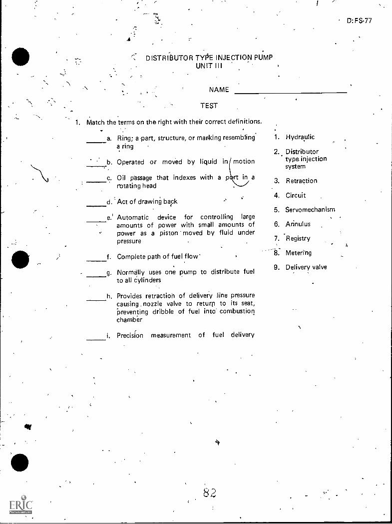
1. Match the terms on the right with their correct definitions.
a. Ring; a part, structure, or mar4dng resemblinga ring ,
b. Operated or moved by liquid in motion
c
c. Oil passage that indexes with a p rt in arotating head
d. ' Act of drawing baFk
e. Automatic device for controlling largeamounts of power with small amounts ofpower as a piston moved by fluid underpressure
f. Complete path of fuel flow
g. Normally uses one pump to distribute fuelto all cylinders
h. Provides retraction of delivery Irne pressurecausing . nozzle valve to returp to its seat,-preventing dribble of fuel into" combustionchamber
i, Precision measurement of fuel delivery
,
1r
D: FS-77
1. Hydraplic
2.. Distributortype injectionsystem
..
3. Retraction
4. Circuit
5. Servomechanism
6. Arinulus
7. -Registry
8. Meterrng
9. Delivery valve
,A

2. Identify the main parts of a distributor type pump.
r re,
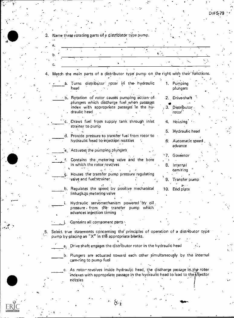
3. Name three rotating parts Of a distrintOr Wipe pump.
D.+8:79
,..
4. Match the main parts of a distributor type pump on the right with their'itiriPtions.
, -, - a. Turns distribUtor* rotor iri the- hydraulic 1. Purpping
head , plungers
Rotation of rotor causes pumping action -of-plungers which discharge fuel \when passagesindex with appropriate passagei in the hy-draulic head
'c. Draws fuel from supply tank through inletstrainer to purrip
a. Provide pressure to transfer fuel from rotor to -
hydraulic head to-injection-nozzles
"e., 'Actuates the pumping,plungers,
f. Contains the tmetering vajve end thein which the rotor revolves,
. S r
1g. Houses the- transfer pump pressure regulating' yeive_and fuel's-trainer.
b. Regulates the speed, by posiii,ve mechanicalli nkage...to rnetering-valve
bore
I. Hydraulic servomechanism poWered tby oil .pressure , from th'e- transfer pump whichadvances injection timing
j. -Contains all component parts
>
-2., Driveshaft
3. Distributor ,rotor
,
4. HoUsing
.5.
8.
9.
Hydraulic head
Automatic speedadvance
Governor
Internalcarrvring
Transfer pump
10. End plate
5. Select true statements cOncerning the principles of operation of apump by placing-an "X" in th% appropriate blanks.
d istributor type
a. Drive shaft engages the distributor rotor in the hydraulic head ,
b. Plungers are actuated toward each other simultaneously by the internalcam-ring to pump fuel
c. As rotor revolves inside hydraulic head, the discharge passage iph'indexes with appropriate passage in the hydraulic head to lead to thenlYzzles
4164r-
rotorJijector

80
- So
"/
-4
16. Arrange in order the steps In which fuel -flows r.fii4ring a cdmplete.pump cycle on 'a ,distribtltor type pump.
. - .
/ ..5-----6-a. Fuel ,flows around te annulus to toppassages to meteringvalve . ,
; .,
b. Fuel trapped between the plungers isithenthe nogle
of sleeve and through connecting'
dlivered through delivery valve to
Transfer pump pressure increases with speed
t
d. -"Fuel is drawh 'from the supply tank i to the pump through the inlet strainer
-1.by t,.. he vane type fuel transfe, r pUrn ,
'-'e. Metering yal-ve regulates the flow of fuel into the4arging ring which incor-
porates the charging ports ., -,
f.
9.
-:., . ,, .Transfer pump prissure forces fuel through drilled passages in the hydraulichead into the annulus , -:.- ,, - ,
',ItAs the rotor revolves, the twin inlet 'passages register with two charging'ports in the hydraulic head allowingluel to flow into the pumpiiig cylindert
h. With further rotation, tlfe inlet passages move obi of registry and the-singledischarge poFt iS opened,
i. The rollers colitaot the cam lobes forcing:the plungers together-
7. Select true statements concerning -61iarging cycle pperation -by placmg an "X" inthe appropriate blanks.
a. When the rotor revolves, the angled inlet passages, in thelotor line up withthe-charging ports-of the charging Hng
b. Pressurized fuei from ,t1-ie transfer pump, controlled, by 'Vie Opening ofthe metering valve, flows to the pumping pylinders forcing" all plungerstogether
e. The plUngeh move outward enodgii tc; supply the correct 0/entity offuel for the engine load
8. Complete the following list of statements concerning discharje cycle operation.
-a. ' As the rotor t ontinues,to revolve, the angled,inlet passages longer line up withthe
b. Fuel is momentarily/rapped until the rotor discharge passagbines up with one ofthe
. c. The rolles contact the cam-lobes and are forced together
0
d. Eitel is then forced through the axial passage of the rotor, then tb the
Q
uU"-,..\
40

D:FS-81
e. Delivery of the fuel wi*continue until the rotors pass theon the cam
The fuel pressure in the axial passage is then reduced to a point where the injec-tion nozzle closes
9. Select true statements concerning delivery valve operation by placing an "X" in theappropriate blanks.
a. Controlled line retraction is the most important jo l? of the delivery valve;this is accomplished by reducing injection line pressure to a point lower thanthat of the nozzle closing pressure
b. The delivery valve is located in a drilled passageway in the center of the rotor
c. There is a delivery valve for every cylinder .d. As injection begins, fuel pressure moves the delivery valve off its shoulder to
allow the volume of its displacement to enter the cavity that houses the0,delivery valve spring.
e. This displaces a similar volume of fuel in the spring cavity before deliverystarts through the valve ports
f. At the end of injection, the pressure on the plunger side of the delivery valveis increased, allowing the cam rollers to fall into the retraction step of thecam lobes
-6. As the valve moves, back, the fuel is removed from the spring cavity andflows through the rotor intake ports then, as the rotor revolves, it is trapped
10. Select true statements concerning return fuel oil circuit functions by placing an "X" intlie appropriate blanks.
a. Transfer pump pre'ssure is discharged into a cavity in the hydraulichead
b. The lower part of this cavity has a vent passage connected to it
c. Should air enter the transfer pump, it will be bled off and returnedtothe fifel tank
11. Name three functions of an end plate.
a.
b.
C.s.
Ar

82
12. Complete a list of optional features of a distributor type pump.
a. Viscosity compensator
b.
c. Automatic load advance
,d.
e.
f. Electric shut-off
13. Demonstrate the ability to:
a. Remove a distributor type pump from an engine.
b. Bench test a distributor type pump.r.
c. install a distribytor type pump on an engine.
(NOTE: If these activities have not been accomplished prior to the test, ask yourinstructor when they should be completed.)
5
4

A
t'
1. a. 6b. 1
c. 7d. 3e. 5
DISTRIBUTOR TYPE INJECTION PUMPUNIT III
f. 4g. 2h. 9
8
ANSWERS TO TEST
2. a. Drive shaftb. Distributor rotorc. Transfer pumpd. Pumping plungerse. Internal cam-ringf. Annulus in hydraulic headg. End plateh. Goernori. Automatic advancej. Housing
3. a. Drive shaftb. Distributor rotorc. Transfer pump blades'
4. a. 2 f. 5b. 3 g. 10c. 9 h. 7d. 1 i. 6e. 8 j. 4
5. a, b, c
6. a. 4 f. 2b. 9 9. 6c. 3 h. 7d.e.
1
5i. 8
7. a, c
8. a.b.d.e.
Charging portsHead outletsInjection lineHigh point
9. a, b, d, e
10. a, c
,
D:FS-83
eV'
84
a. Provides fuel inlet passages and houses pressure regulating valveb. Covers the fuel transfer pumpc. Absorbs end thrust of drive and governor.,
12. b. Centrifugal governord. Automatic speed advancee: Torque control
13. Performance skills evaluated to the satisfaction of the instructor
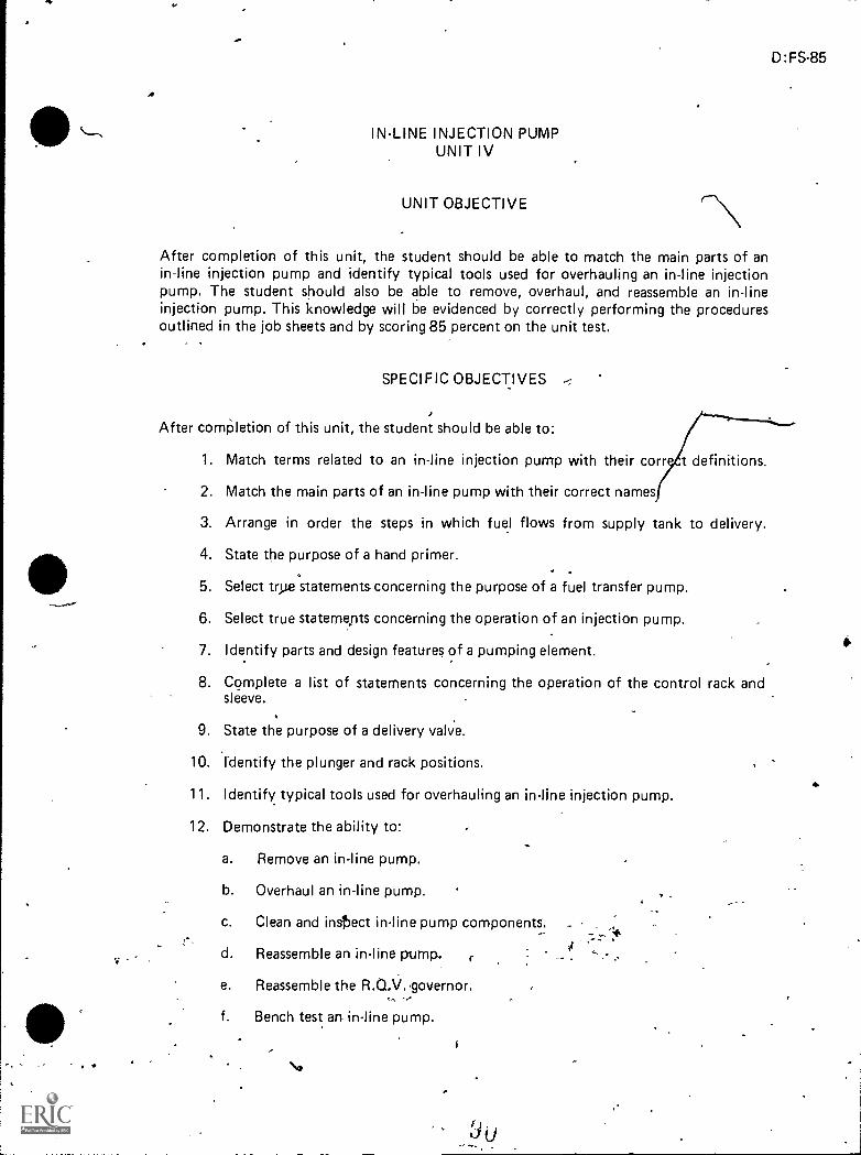
.00
IN-LINE INJECTION PUMPUNIT IV
UNIT OBJECTIVE
After completion of this unit, the student should be able to match the main parts of anin-line injection pump and identify typical tools used for overhauling an in-line injectionpump. The student should also be able to remove, overhaul, and reassemble an in-lineinjection pump. This knowledge will be evidenced by correctly performing the proceduresoutlined in the job sheets and by scoring 85 percent on the unit test.
SPECIFIC OBJECTIVES
After comPletion of this unit, the student should be able to:
1. Match terms related to an in-line injection pump with their corr t definitions.
2. Match the main parts of an in-line pump with their correct names
3. Arrange in order the steps in which fuel flows from supply tank to delivery.
4. State the purpose of a hand primer.
5. Select trAe statements concerning the purpose of a fuel transfer pump.
6. Select true statemepts concerning the operation of an injection pump.
7. Identify parts and design features of a pumping element.
8. Complete a list of statements concerning the operation of the control rack andsleeve.
9. State the purpose of a delivery valve.
10. Identify the plunger and rack positions.
11. Identify typical tools used for overhauling an in-line injection pump.
12. Demonstrate the ability to:
a. Remove an in-line pump.
b. Overhaul an in-line pump.
c. Clean and intect in-line pump components.
d. Reassemble an in-line pump. r
e. Reassemble the R.O.V..governor.
f. Bench test an in-line pump.
D:FS-85
6

IN-LINE INJECTION PUMPUNIT IV
SUGGESTED ACTIVITIES
I. Provide student with objective sheet.
II. Provide student with information and job sheets.
Ill. Make transparencies.
IV. Discuss unit and specific objectives.
V. Discuss information sheet.
VI. Demonstrate and discuss the procedures outlined in the job sheets.
VII. Provide appropriate service manual for pump used in your shop.
VIII. Show students how to use a service manual.
IX. Provide operation manual for test stand you will be using.
X. Advise students that International Harvester tools/numbers will be referencedin Job Sheets #2, #4, and #5.
Xl. Give test.
4
INSTRUCTIONAL MATERIALS
I. Included in this unit:
A. Objective sheet.
B. Information sheet
C. Transparency masters
1. TM .1--In-Line Injection Pump
2. °TM 2--Mairi Pump Parts
3. TM 3--Fuel Flow
4. TM 4--Injection Pump Operation
5. TM 5--Parts and Design of Pumping Element
6. tfA 6--Control Rack and Sleeve-
7. TM 7--Plunger Pations at Fuel Delivery
8. TM 8--Special Rebuild Tools .
9i
D:FS-87
A

88
1
D. Job Sheets
1. Job Sheet #1--Remove art In-line Pump
2. Job Sheet #2:-Overhaul an In-line Pump
3. Job Sheet #3-Clean and Inspect In-line Pump Components
4. Job Sheet #4--Reassemble an In-lind Pump
5. Job Sheet #5-- Reassemble the R.Q.V. Governor
6. Job Sheet #6--Bench Test an In-line Pump
(NOTE: Illustrations which appear in Job Sheets 2, 4, and 5 of this unitare courtesy of International Harvester.)
E. Test
F. Answers to test
II. References:
A. Toboldt, William K. Diesel Fundamentals; Service, Repair. South Holland,IL: Goodheart- Willcox Company, Inc., 1980.
B. Kates, Edgar J., and Luck, William E. Diesel and High Compression GasEngines. Third Edition. Chicago: American Technical Society, 1974.
C. Fundamentals of Service: Engines. Fifth Edition. Moline, I L: Deere andCOmOany, 1980.
D. Technieal Manual: John Deere Fuel Injection Equipment Robert Bosch.Moline, I L: Deere and Company, April_1974.
E. Fuel System: Fuel Injection Poop - Robert Bosch "A" Type for,DV-462Band DV-550B Engines. Chicago: 'I nternational_Harvester Co.
F. Dagel, John F. Diesel Engine Repair. New York:. John Wiley and Sons,Inc., 1982.
,
G. Foutes, William A. Diesel Engine Mechanics. Stillwater, OK: *id-AmericaVocational Curriculum Consortium, 1977.
A

IN-LINE INJECTION PUMPUNIT IV
INFORMATION SHEET
I. Terras and definitions
dr A. In-line injection pumpUses an individual pump for each cylinder withPumps mounted in-line (Transparendy 1)
,
B. Annular grooveMachined recess forming a ring on pumping.plunger
C. Vertical slot--Located at right angles to the plane of the supporting surface
D. Helix--Spiraled, machined recess on pumping plunger
E. Gallery--Long, narrow fuel or oil passage
F. Aneroid--Device which limits fuel supply to engine, preventing e moke
G. Transfer prp (supply pump)--Sends fuel at low pressure th ugh filtersto the injection pump
I I. Main parts of in-line pump (Transparency 2)
A. Aneroid
B. Individual pumping element41
C. Injection line
D. Leak-off line
E. Pump housing
F. Hand primer
G. Sediment bowl
H. Fuel transfer pump
I. Camshaft
J. Control rack
K. Governor
Fuel flow from supply tank to delivery (Transparency 3)
A. Fuel is drawn from supply tank through primary filte' by fuel transferpump
D:FS-89
,e1V

90
INFORMATION SHEET
B. Transfer pump forces fuel unde,c low pressure through secondary filterand through final stage'filter to each injection pumping element
C. Pumping element meters fuel at high pressure to each injection 'nozzlefor dehvery to coThbustibn chamber
Purpose of hand primer Hand primer on fuel transfer pump carr be operated byhand to pump fuel when bleeding the system (Transpiirency 4)
V. Purpose of fuel transfer pump
A. Drawt fuel from J uppIy tank through primary filter
B. Assures fuel supply to injection pumping elements
iNOTE: Ali fuel flows through a preliminary filter in the transfer pumpsediment bowl.)
VI. Injection pump operation (Transparency 4)
A. Plunger type pump has engine dnven camshaft rotating at half engine speed
B. Roller cam followers, nding on cam lobes, "Opei-ate the plung'ers to supplyhigh pressure fuel through delivery valves eo injection nozilesl
VII. 'Parts and design features of pumping element (Transparency 5)
A. Spill ports
B. Plbinger
C. Annula,r groove
D Barr&
E. 'Helix
Vertical slot
VIH Operation of control rack and sleeve (Transparency 6)
A. Governor Moves rack-to regulate speed of engine
.8. Th t?. sleeve, irC;tated h / the control rack, is fitted over the barrel and connectsto the vanes on the plunger,
C. ,Plunger rotation opens or closes the hehx which meters the quantity of fuel, for dehvery to cyhnder

e
4
,
I&
\
-
. D:FS-91
INFORMATION SHEET
IX. Purpose of delivery valve--The'delivery valve creates a sudden pressure dropin the delivery line causing the injector nozzle valve to close instantly (Trans-parency 6) *,
(NOTE: This effect prevents dribbling at the nozzle.)
X. Plunger and rack positions (Transparency 7)
A. No fuel delivery !B. Partial fuel delivery
C. Maximum fuel delivery
Xj. Typical tools used for overhauling an in-line injection-pump (Transparency 8)
(NOTE: The tool numbers listed below and on Transparency 8 refer to Interna-
-
tional,Harvester tools only and will be used in upcoming job sheets.)
eA. SE-2119--Rack gauge holder
B. SE-2121--Dial indicator (inch reading).
C. S-2339--Wrench, holding, drive flange
D. SE-2340--Remover, governor flyweight damper
E. SE-2341--Holder, tappet . /iF. SE-2342--Gauge, caMshaft protrusion
G. .SE-2343--Holder, dial indicator,
H. SE-2344--Remover and installer, camshaftcylindrical nut
l.' E-2345--Remover and installer, tappet
J. S-2346,Rérnover and installer, barrel plunger
K. SE-2347--Wrench, tappet adjusting- .
L. SE-2348--Wrench, governor spring adjusting
M. SE-2349--R ver and installer, governor spring and adjusting screw
-
N. . SE-2351--Fixture, pump holding
1.
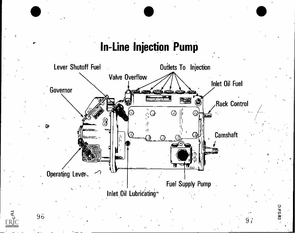
In-Line Injection Pump
Lever Shutoff Fuel
Valve Overflow
Ouilets To_ injection
Inlet Oil Fuel
Rack Control
, Operating Levtr,
9 6 /0
Fuel Supply Pump
LubriCkinr
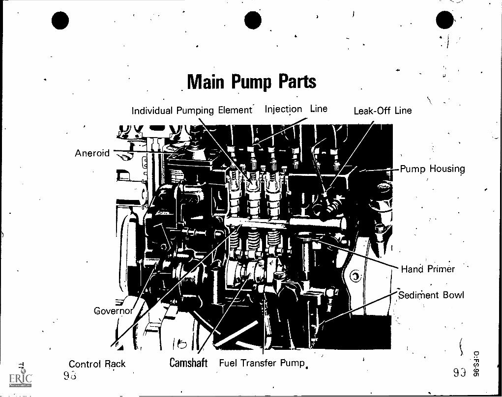
. Main Pump Parts
,
Aneroid - l
Individual Pumping Element. Injection Line
vr ow I
Governor
eA
-0
_
.1,
1
, )! (
4.P
\Leak-Off Line
%BM
osii @,
:
i\
..
--4 Control Rack Camshaft Fuel Transfer Pump.Kr.) 9
.&
7
,
Pump Housing
lf)
iHand Primer..
,Sedirhent Bowl

o
,
0-60 lbs.
Gaugez,
,z
: t.
t .,
Fuel Flow.,-,f.
.Bleeder Screw
..
Nozzle Holder ..
Final Stage Filter
-4-471. Drain Screw
Secondary Filter ..
j
I%
.00,0
$
4.
.
..
,Primary Filter--*- .
i
t
,-
Drain ScrewSupply Tank 0
:41u)cb.,,

o
7
CT
`.
h
vs
4.
0
If
.1
Ar
f
,
< )
, ,
..
Inject Ofi Pump Operation
n
-.
..i
i
. Delivery Line
Delivery ValveJ
Barrel.
,
Plunger
Control Rack
Hand Primer -,
Control SleevePlunger VaneSpring
Spring Plate
..1
A.
./ '
;
t
D:FS-9g
,
e
Cam Follower 9
TpaftCahi .
Fuel Transfer Pump
. Sediment Bowl ..
,
-
.
lk
.I.
,
TM 4
I

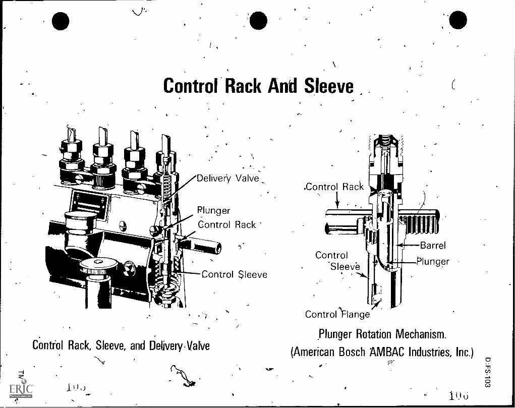
Control Rack And Sleeve
Delivery Valve_
Plunger
Control Rack
Control Sleeve
Contfol Rack, Sleeve, and DeliveryNalve
I
.Control
ILRack
Control
ICU I
Plunger
Barrel
Sleeve
Controlinange
,Plunger Rotation Mechanism.
(American Bosch AMBAC Industries, Inc.)P'

Plunger Positions At Fuel Delivery
No Fuel Delivery
_II,
Il I
Partial Fuel Delivery
4Wid
III
III
IL
Maximum Fuel Delivery.
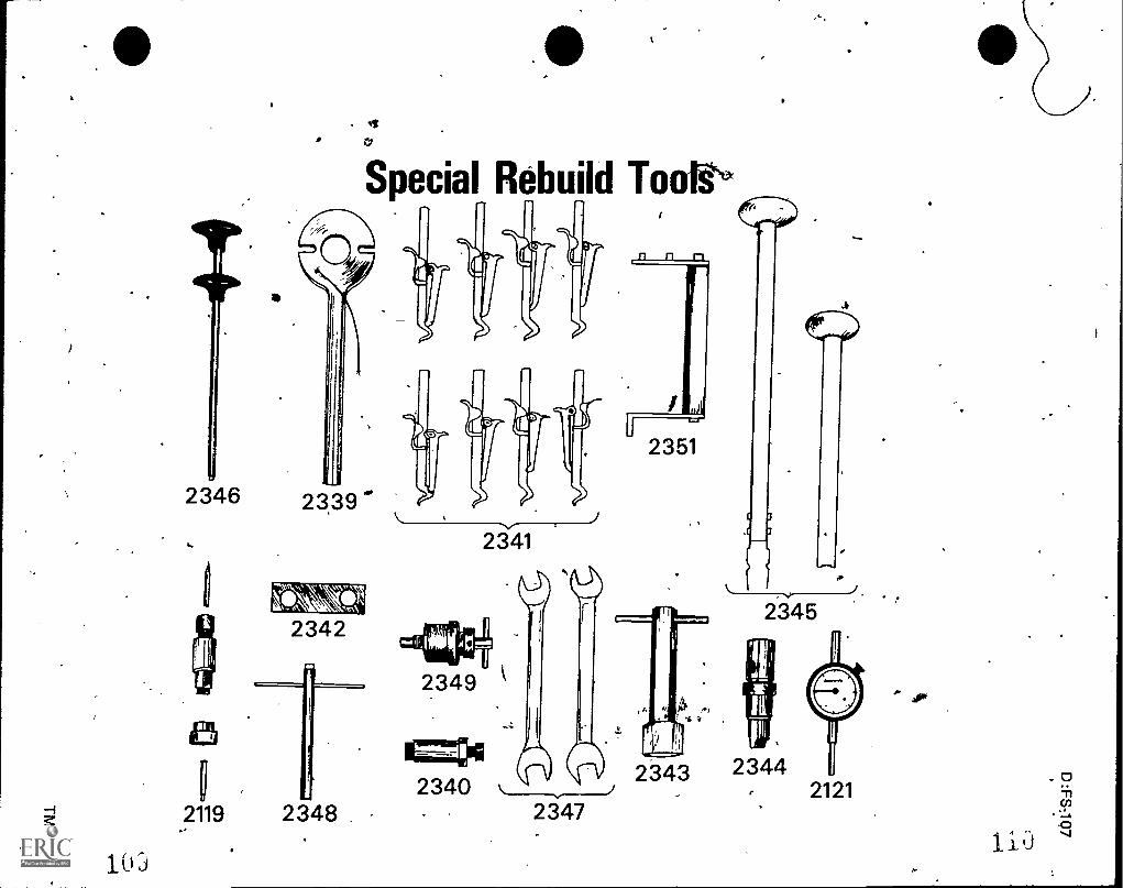
2346
4
Rebuild Tookse
2339
2342
2119 2348 .
1 0 j
2 341
2349
2351
11=1412 3 43
2 3402347
to
234 5
234421 21
D:FS-109
IN-LINE INJECTION PUMPUNIT IV
JOB SHEE#1--REMOVE AN IN-LINE PUMP
I Tools and materials
A. Basic hand tool set, including metric
B. Appropriate service manual
C. Clean shop towels
D. Clean line plugs
E. Clean diesel fuel
I I. 'Procedure
(CAUTION: Follow all shop safety procedures.)
(NOTE: Engine should be static timed before parts are removed.)
A. Disconnect and remove accelerator rod and shut-off control cable fromgovernor -
(NOTE: Before removing fuel lines, clean pump and connections with cleandiesel fuel.)
B. Disconnect injection lines, low pressure lines, and lube oil line from pump
C. Remove any brackets necessary
D. Install protective caps on all fuel lines and pump outlets
E. Rerove pump stabilizing brackets
F. Remove adapter moun-ting bolts which hold pump adapter and pump hous-ing to rear of engine front cover
G. Pull pump _to rear to free.drive_flange tangs from mid.dle clisc
H. Lift pump from the engine

J^.
1N-LINE INJECtION PUMPUNIT IV
JOB SHEET #2--OVERHAUL AN 1N-LINE PUMP
I. Tools and materials
A. Basic hand tool set, including metric
B. Appropriate service manual
C. Typical tools as recommended by appropriate manufacturer'
(NOTE: The tool numbers listed below are International Harvester.)
1. SE-2339 Wrench, bolding, drive flange
2. SE-2340 Remover, governor flyweight damper
3. SE-23411-lolder, tappet A
4. SE-2344 Remover and installer, caMshaft cylindrical nut
5. SE-2345 Remover and installer, tappet
6. SE-2351 Fixture, pump holding
D. Clean pans
E. Clean shop towels (lint-free)
F. Clean tools
G. Clean work area
H. Clean work bench
I. Clean vise
Procedure
A. Disassemble governor
1. Clean the external parts of the pump thoroughly before disassembly
2. Drain fuel and lubricating oil from pump and governor housings
3. Cap or plug fuer and lube oil openings after draining
4. Clean the exterior of the governor and pump housing with clearviieselfuel
D:FS-111

112
JOB SHEET z.--2
4
5. Clamp holding fixture SE-2351 in the vise and secure injection pumpwith two bolts (Figure 1)
HOLDING FIXTURE SE-2351
MT-4221 FIGURE 1
6. Use a 10 mm Allen wrench, and remove plug rf-rOm 1.acl<1 link adjustmentaccess hole in top of governor housing
7. Remove seal and remove rack mounting bolts on pumps with a controlrack stop
(NOTE: On pumps with torque capsule, reMove seal wire, removetorque capsule cover and gasket, and remove torque capsule mountingscrew bushings. See Figure 2.)
TOROUE CAPSULE(ROV GOV )
STOPSHACKLE
MT-9054 FIGURE 2

D:FS-113
JOB SHEET #2
8. Move ccelerator lever fully back against low idle stop screw
9. Re h through the rack link acceis hole with a small screwdriver(Fi re 3.)
10. Pry stop shackle aside lightly (right side ag viewed from the rear ofpump) and disengage stop shackle from rocker arm pin (Figure 3)
SCREWDRIVER
TORQUECAPSULE
k .
FIGURE 3
11. Pull control rack stop or torque capsule to the rear to clear mountingstuds
12. Rotate assembly approximately 45 de6rees counterclockwise and slideout of governor housing
13. Remove slotted screw guide i4-144 from governor cover (Figure 4)
SLOTTED SCREW GUIDE PIN
FIGURE 4
6

arn,
V T.
114
JOB SHEET #2
14. Remove mounting screws and take off, governor, cs.ter (Figure 5)
GOVERNOR COVERLINK PIN
ACeELERNOR LEVER
RACK LINK
c
ftNr-N,
111,
-1z-'5'FLOATI4G LEVER
Mr'9223 FIGURe5.,
-
15. Operate accelerator lever to release linkage
16. Remove cotter pin and link.pin
17. Disconnectilloatingi-dtier from i-ck link
18. Pull top of floating lever back and down to remove floating-leverand slider from adjusting pin
19. Raise tabs on lock washer and remove double-nutted thrtkbolt andadjusting pin from the governor flyweight assembly (Figure p)
THRU-BOLT
?1..1;WEIGHT A
ADJUSTING PINM1-9225 FIGURE 6
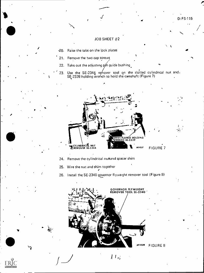
vs
JOB SHEET 42
D:FS-115
20. Raise the tabs on the Ind< plates .4*
21. Remove the two cap screws
22. Take out the adjusting p n guide bushing.
23. Use the SE-234,S re over tool qn the slotted cylindrical nut and.1 SE-2339 holding v-vre ch to hold the camshaft (Figure 7)
4,
j
r.DRIVE FLANGE HOLDINGWRENCH SE-2339
vei YLINDRICZ. NUTEMOVER SE-2344
24. Remove the cylindrical nuland spacer shim
25. Wire the nut and shim together
°4"227 FIGURE 7
26. Install the SE-2340 gc.....ivernor flyweight remover tool (Figure 8)
GOVERNOR FLYWEIGHTREMOVER TOOL SE-2340
MEM to-9221 FIGURE 8
+.

116
JOB SHEET #2
27. Remgve the flyweight assembly
(NOTE: Do not disassemble any further.)
28. Remove the rack link, link bracket, and spring from the rear of the 4;fr
control rack to remove the governor housing
B. Disassemble in-line pump
(NOTE: The main body contains several fittings bushings, and plugs onwhich Loc-Tite has been used. Do not remove these part& unless they areleaking.. Among these are the inlet fuel adapter, the fuel gallery plug, thelube oil inlet bushing, and ;the bleeder valve bushing.)
1. 'Remove the side cover4.
..2. Remove side cover gasket from cover and housing
Remove transfer pump and gasket
4. Install eight SE-2341)tappet holder topls (Figure 9 inside of pump tohold all tappets up from the camshaft
(NOTE: To prevent tool breakage, lift each tappet by rotating camshaftbefore installing hoi ol.)
TAPPET HOLDER, SE-2341Nt, lc , la
WRENCil SE-2339
;2."-
FIGURE 9

....,f
filk
I
4
-,
,
......,-. D:FS-117
....-
JOB SHEET #2
..
.4
5. Remove camshaft not and washer using SE-2339 holding wrench tohold drive flange (Figure 10)
vDRIVE FLANGE
WRENCH SE-2339
SOCKET WRENCH
FIGURE 10
6. Remove the drive flange by using a gear puller or by removing thetwo socket head set screws, flat washers, and lock washers from the
idriveflanges; reinstall the set screws and place two steel strips behind
the drive flange; run the screws in evenly until flange is removed
(NOTE: Do not lose the woodruff key.)
7. Rotate pump in holder so that the tappet holder tools are pointingupwards
8. Remove the two camshaft center bearing screws from the bottom ofthe pump
9. Use a large screwdriver and remove the four flat head screws fromcamshaft front bearing retainer
. 10. Remove retainer I
4 11. Remove camshaft, including center and end bea)ngs from front ofpump
12. Use a 5/8" socket and drive the eight base plugs inskie ).1,(e governorhousing and remove them
13. Use the SE-2345 tappet remover tool and ptIsh the roller tappet up(Figure 11) \
#
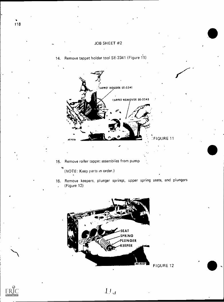
.,
.
118
,
JOB SHEET #2
14. Remove tappet holder tool SE-2341 (Figure 11)
-446.,
::TAPPET HOLDER SE-2341
TAPPET REMOVER SE-2345
I
4.0ipolkN......
MT.1234
15. Remove roller tappet assemblies from pump
t)(NOTE: Keep parts in order.)
' :FIGURE 11, .
16. Remove keepers, plunger springs, upper spring seats, and plungers, (Figure 12)
SEAT
SPRING
PLUNGER
KEEPER
.I i d
MT-9237 FIGURE 12 -.
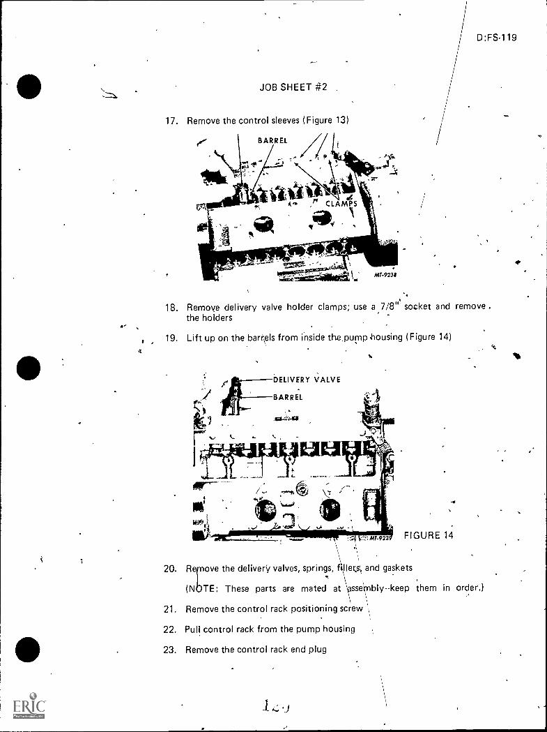
1'
D:FS-119
JOB SHEET #2
17. Remove the control sleeves (Figure 13)
18. Remove delivery valve holder clamps; use a 7/8" socket and remove .the holders
19. Lift up on the barr\els from inside the.purnp.housing (Figure 14)
DELIVERY VALVE
BARREL
\elie-44411
tor
,
20. R ove the delivery valves, springs, f lleK.s\ and gaskets,
FIGURE 14
(N TE: These parts are mated at sse bly--keep them in order.)
21. Remove the control rack positioning screw
22. Pull control rack from the pump housing
23. Remove the control rack end plug

4
1N-LINE INJECTION PUMP*UNIT IV
JOB SHEET #3--CLEAN AND INSPECT IN-LINE PUMP COMPONENTS
I. Tools and materials
A. Appropriate service manual
B. Clean shop towels (lint-free)
C. Crocus cloth
D. Clean diesel fuel
E. Clean parts tray
Procedure
(CAUTION: Follow an shop safety procedures.)
A. Clean and inspect an parts before reassembling to the pump
B. Usg clean fuel oil to wash parts
i
(NOTE: When inspecting for damage or it is good practice to replaceany pact that s questionable.)
C. Look for the following items when inspecting ior damage or wear
D:FS-121
1; Governor housircg4tncl cover should be inspected for cracks, strippedthreads, and burrs
2. Governor weight assembly should be checked for worn bell cranks,damaged weights, stripped nuts, and worn springs'
3. Damper hub assembly should be checked for condition of rubberbumpers
4. Curve template sliding parts should not bind any grooves or pressuremarks or curve should be smoothed with fine emery
5. Adjusting pin should be inspected lor wear and replaced if any isvisible
6. Pump housing should be inspected for cracks, chips, overtorbuingor stripped screw threads; if the housing leaks, it cannot be repairei
7. Plungers and barrels should be Inspected, for scoring and scratches
8. Barrels and plungers can be tested by washing in test oil, and pulling theplunger part way out of the barrel; the plunger must fall back slowly byits own weight
,t,
122
JOB SHEET #3
9. Delivery valve and seat should be replaced if any damage 'is present
10. Roller tappets tan be polished with crocus cloth; if tappets do notpolish out, they must be replaced
11. Camshaft should be inspected for grooving on cams and bearing sur-faces; if damaged, the camshaft must be replaced
12. Roller bearings should be ceplaced if worn
13. Control rack needs to be checked for binding in the Musing; thegear teeth should be checked for burrs and scratches
14. Control sleeves can be polished and reused if only minor damageis present
15. Spring can be reused if not broken or rUsted
16. Spring keepers can be reused unless bent or worn
17. Base plugs can be reused unless they are known to be leaking
18. Replace all gaskets, seals, and 0-rings

IN-LINE INJECTION PUMPUNIT IV
JOB SHEET #4--REASSEMBLE AN IN-LINE PUMP
I. Tools and materials
A. Basic hand tool set, including metric
B. Appropriate service manual
C. Typical tools as recommended by appropriate manufacturer
(NOTE: The tool numbers listed below are International Harvester.)
1. SE-1848 Dial fndicator set
2. SE-2341 Holder, tappet
3. SE-2342 Gauge, camshaft protrusion
-4. SE-2343 Holder, dial indicator
5. SE-2345 Remover and installer, tappet.
6. SE-2351 Fixture, pump holding
D. Fuel oil
E. Clean pans
F. Clean shop towel's (lint-free)
G. Clean tools
H. Clean work area
I. Clean work bench
J. Clean vise
D:FS-123
00-

124
JOB SHEET 44
Procedure
(CAUTION: Follow all shop safety procedures.)
A. Position pump body in'SE-2351 holder and clamp upright in vise (Figure1)
Et.
AA
on,fi 0 MY
MT.1221
WHY#4L";SI
',-HOLDING FIXTURE 5E-2351
'1. Place new gasket on governor housing
FIGURE 1
2. Coat thre gasket with a light lubricant and install the governor housingby tapping lightly with a soft hammer
3. Install and stake governor mounting screws
Rebuild-main pump
1. Place the barrels in correct order, aligning the guide slots with pins inpump housing
(NOTE: Pre lubricate with fuel oil while installing.)
2. Install delivery valves and seats, noting that the flat is located on valvesfor the four idling cylinders (cylinders numbered 2, 3, 5, 8)
3. Install delivery valve gasket
4. Install springs
5. Install fill piece and holders
6. Use new 0-rings and prelubricate with fuel oil
124

D:FS-125
JOB SHEET #4
7. Install delivery valve holders finger tight
8. Attach rack link bracket and rack link to the rack
9. Place rack spring and washers in place on rack
10. Install the control rack through the governor and into the pump hous-ing
(NOTE: The rack spring is important; it takes up lost motion in theinternal pump parts and serves to retract rack if other linkage should
11. Make sure the rack is free and secure it with the rack positioningscrew
12. Rotate pump so the tappet cover side is up
13. Install control sleeves on barrek (Figure 2)
BARRELS
CONTROL SLEEVES
MT.9243 FIGURE 2
14. Center all eight control sleeves on the rack segments
15. Move the control rack to see if any sleeves bind and replace any that do
-7( (NOTE: When a sleeve binds, replace with the next smaller size.)
16. Start at the drive end and torque #1 through #8 delivery valve holders22 to 25 ft. lbs.
00(NOTE: Torque twice.)
17. Install tlie upper spring seats and springs
1 - 3

126
JOB SHEET #4
18:. Use the plunger installer tool (Fture 3)
41,
PLUNGERSPRING KEEPER
PLUNGER INSTALLER SE-2346
00-,244
19. Place the spring keeper on the tool
FIGURE 3
20. With marked tong of plunger toward side cover opening and open endof spring keeper away from side cover opening, install plungers andspring keepers in their respective barrels
21. Align the plunger tong with the control slot
22. Use the SE-2345 tappet installation tool, taking care to keep theroller pin flush with the tappet
23. Compress the plunger springs with SE-2345 tappet installation tool
24. Position all eight SE-2341 tappet holder tools on side of pump housingto hold all tOpets in their raised position (Figure 4,)
-4.4'TAPPET HOLDER SE-2341
TAPPETINSTALLER.SE-2345
MT-9245
FIGURE 4

-14
10.
D:FS-127
-JOB SHEET #4
25. Place a small dab of grease on the center bearing to hold it to thecamshaft
26. Install the camshalt into the pump housing
27. Secure the center, bearing with two screws through- the bottom ofthe pump housing
28. Use a thin coat of non-hardening sealer on the frOnt bearing retainerand set retainer in place
29. Start a-II four screws to guide the retainer in place
(NOTE: Do not use screws to draw the' retainer down, just to guidelt",...
30. Tap retainer into place while turning the camshaft to assure alignment(Figure 5)
, FRONT BEARING RETAINERIt
t% CAMSHAFT
SOFT HAMMER._-"169irit 444.. .4,
31. Tig-fiten mounting screws securely
FIGURE 5
7

.00
128
a
r,
JOB SHEET #4
32. Check camshaft end play (Figure 6)
(7-
DIAL INDICATOR SET SE-1848
DPLAY HOLDER TOOL SE-2343
FIGURE 6
33. Screw SE-2343 holder tool'onto front end of camshaft
M1.9247
34. Place SE-1848 dial indicator set in holder so indicator Will read endplay when tool handle is pulled and released
35. Set end play at .02.06 mm (.0008-.14)
36. Change end play by adding or removing shims behind the front bearings
37. Check camshaft protrusion (Figure 7)
.11-1Wlit DEPTHMICROMETER
PROTRUSION GAUGESE-2342
CAMSHAFT
FIGURE 7
38. Check space between the drive coupling and main body; use the SE-2342 protrusion gauge and depth micrometer
39. Place gauge over front end of camshaft
40. Use the depth micrometer and measure from the surface of the_toolto the machined surface of the pump housing

D:FS-129
JOB SHEET #4
411 Check the distance; it should be 20.7-22.2 mm (.817-.877)
42. Change camshaft protrusion by adding shims under the bearing atthe governor end of the camshaft
43. Install woodruff key in camshaft slot
44. Install the drive flange on camshaft
45. Install lock washer and nut and tighten to 60-72 ft. lbs.
(NOTE: Check the two halves of the drive flange to be sure matingmarks are together. Torque t4 sbcket head set screws in drive flange18-25 ft. lbs.)
46. Use the camshaft to release pressure on the SE-2341 tappet holdertools and remove them from the sidA of the housing
47. Install the base in the bottom of the pump housing using 5/8" or11/16" socket or similar size wood dowel (Figure 8)
BASE PLUGS
.:s):.../
WOOD DOWEL4.
MT-9249 . FIG'URE 8,
48. Seat plugs so they are just past the lower edge of chamfer ih the pumphousing
49. Install a new gasket 'and transfer pump to side of pump housing
50. Secure with three mounting nuts and lock washers
(NOTE: You can check ,the condition of the transfer pump by pressur-izing with air (15-20 psi) agd submerging in oil--no leaks.are permitted.)

L
IN-LINE INJECTION PUMPUNIT IV
JOB SHEET #5--REASSEMBLE THE R.Q.V. GOVERNOR
D: F S-131
-0.0°I. Tools and materials
A. Basic hand tool set
B. Appropriate service manual
C. Typical tools as recommended by appropriate manufacturer
(NOTE: The tool numbers listed below are International Harvester.)
1. SE-2339 Wrench, holding, drive flange
2. SE-2344 Remover and installer, camshaft cylindrical nut
D. Manufacturer's specifications
E. Clean shdp. towels
II. Procedure'
(CAUTION: Follow all shop safety procedures.)
A. Service the governor flyweight assembly as a Olete.,unit (Figure 1)
GOVERNOR FLYWEIGHTASSEMBLY
ADJUSTING NUT
TR(AL SPACERBUSHING
.4.------SPRING SEAT(THREE SIZES AVAILABLE)
1
1 j
MT-9250FIGURE 1
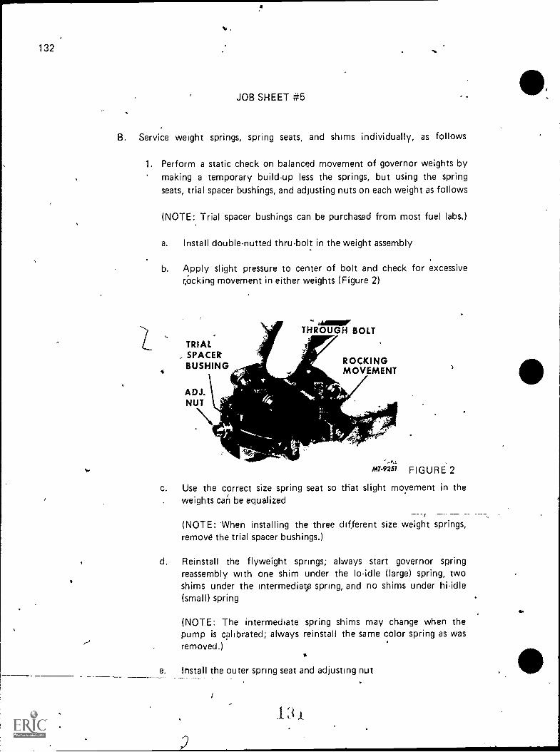
132 "0.
JOB SHEET #5
B. Service weight springs, spring seats, and shims individually, as follows
1. Perform a static check on balanced movement of governor weights bymaking a temporary build-up less the springs, but using the springseats, trial spacer bushings, and adjusting nuts on each weight as foHows
(NOTE:, Trial spacer bushings can be purchased from most fuel labs,)
a. Install double-nutted thru-bolt in the weight assembly
b. Apply slight pressure to center of bolt and check for excessivecocking movement in either weights (Figure 2)
TRIAL- SPACER
BUSHING
VAND..1.\
asmorTHROUGH BOLT
ROCKINGMOVEMENT
_LA
MT-9251 FIGURE 2
c. Use the correct size spring seat so tliat slight movement in theweights caii be equalized
(NOTE: When installing the three different size weight springs,remove the trial spacer bushings.)
d. Reinstall the flyweight springs; always start governor springreassembly with one shim under the lo-idle (large) spring, twoshims under the intermediatp spring, and no shims under hi-idle(small) spring
(NOTE: The intermediate spring shims may change when thepump is calibrated; always reinstall the same color spring as wasremoved.)
e. Install the outer spring seat and adjusting nut
Ei
4.

JOB SHEET #5
f. Install the outer spring seat and adjusting nut (Figure 3)
OUTER CYLINDRICALSPRING SEAT NUT
GOVERNOR LO-IDLEFLYWEIGHT SPRING
MAX-SPEED ALL-SPEED
SPRING SEAT SPRING
ADJUSTING MAX-SPEEDWASHER SPRINGS
ALL-SPEED ADJUSTINGSPRING SEAT SHIM
MT4752
FIGURE 3
D:FS-133
(NOTE: The adjustment range is from flush to not more than2.5 mm [.100"]., protrusion of-the threaded bolt [2 to 3 clicks]Post protrusion should be approximately equal on both springsets.)
C. Inspect darbper buffers for damage and pry up the hub to inspect andreplace as a set, if needed, before installing weight assembly on camshaft(Figure 4)
DAMPER HUB
--arevoRETAINER
BUFFERS
MT-9252
FIGURE 4

134 -P
,
JOB SHEET #5
D. Assemble the prelubricated buffers in damper retainer and place damperhub on weight assembly (Figure 4)
1
1. Install the flyweight assembly to the camshaft (Figure 5)
FLYWEIGHT ASSEMBLY.111111.-14T-9253 FIGURE 5
2. Install spacer shim and secure to camshaft with slotted cylindricalnut, using the SE-2344 and SE-2339 rebuild tools, and torque thenut to 37-43 ft. lbs.
3. Check action of damper by holding camshaft, grasping weight assembly,and twisting to note for slight movement
4. Use -a thicker spacer shim. to obtain more movement or thinner shimto decrease movement
5. Install the adjusting pin guide bushing ...
6. Install adjusting pin assembly; temporarily secure with the thru-bolt atthis time
7. Install slider and floating lever; open slot of the floating lever to right,and pin floating lever to rack link to hold in,place
...
J
-,..----
..
,

D:FS-135
JOB SHEET #5
8. Measure the slider-to-housing distance (Figure 6)
FLOATING LEVER
ADJUSTING PIN
All.1254FIGURE 6
9. Take measurement by measuring from the back of the slider to thegovernor mating surface with no gasket 38.8 mm, 1.524 +/- .015"
10. Change the distance by turning the screw inside of the adjusting pin;one-half turn of the adjusting screw moves sliding block approximately.5mm, .020"
11. Secure the double-nutted thru-'bolt in the governor weight assemblyby installing the lock washer and nut; move the rack and check forfreedom of movement
12... Back out the hi-idle adjusting screw
13. Measure the setting of the curve plate (Figure 7)
ICURVE. PLATE
INCA/0
BASIC SETTING
GASKET
GUIDE PIN
t ft,
MT-9255 FIGURE 7

136
JOBSHEET #5
14. Take measurement from the governor cover surface (gasket in place)to the guide pin shaft when the guide pin is in maximum fuel positionand bottomed in curve plate; setting should be 21.5-21.9 mm (.847-.863"); add shims to decrease the setting (Figure 8)
(NOTE: Make sure cottO pin has been installed between the rack linkand floating lever.)
, .
Alb
4
CURVE PLATE
,Aproopli0
15. Install governor cover to housing
tz-;
741111Pritiii4 MT-9256 FIGURE 8
16. Apply a non-hardening sealer to the guide stud screw and install itin the rear of the governor cover
17. Insta'll accelerator lever ,
18. Place the accelerator lever fully back against the lo-idle stop screw
19. Install torque capsule into governor housing, then rotate torque capsule45 degrees in a counterclockwise direction
20, Slide torque capsule into governor housing until stop shackle clearsgovernor floating lever, then rotate capsule clockwise until in a horizon-tal position
21. Move the accelerator lever into a vertical position

o
D:FS-137
JOB SHEET #5
22. Use a hook made' from light wire and reach down through the adjust-ment access hole and lift up the stop shackle to engage the slot in thestop shackle with the rocker arm pin (Figure 9)
ADJUSTMENT--ACCESS HOLE
TORQUECAPSULE
I fSHACKLE 'II
-a
M ri I
ROCKERARM PIN
GOVERNOR HOUSINGCUTAWAY FORILLUSTRATION
RACK LIN
WIRE HOOK
23. Secure.the torque capsule
E. Check the torque capsule assembly
1. Hold the accelerator lever fully forward (Figure 10)
FIGURE 9
EXCESS FUEL(STARTING)POSITION(ADJUSTMENTSCREW RESTINGON TOP OFMATING FLANGE)
STOP-aSHACKLE
FIGURE 10
2. Move fuel shU -off lever to the rear slowly; if the installation is correct,a distinct click will be heard as the rack moves back
(NOTE: If correct positions cannot be obtained, check for properengagement of slot in stop shackle to rocker arm pin.)
1;i
S
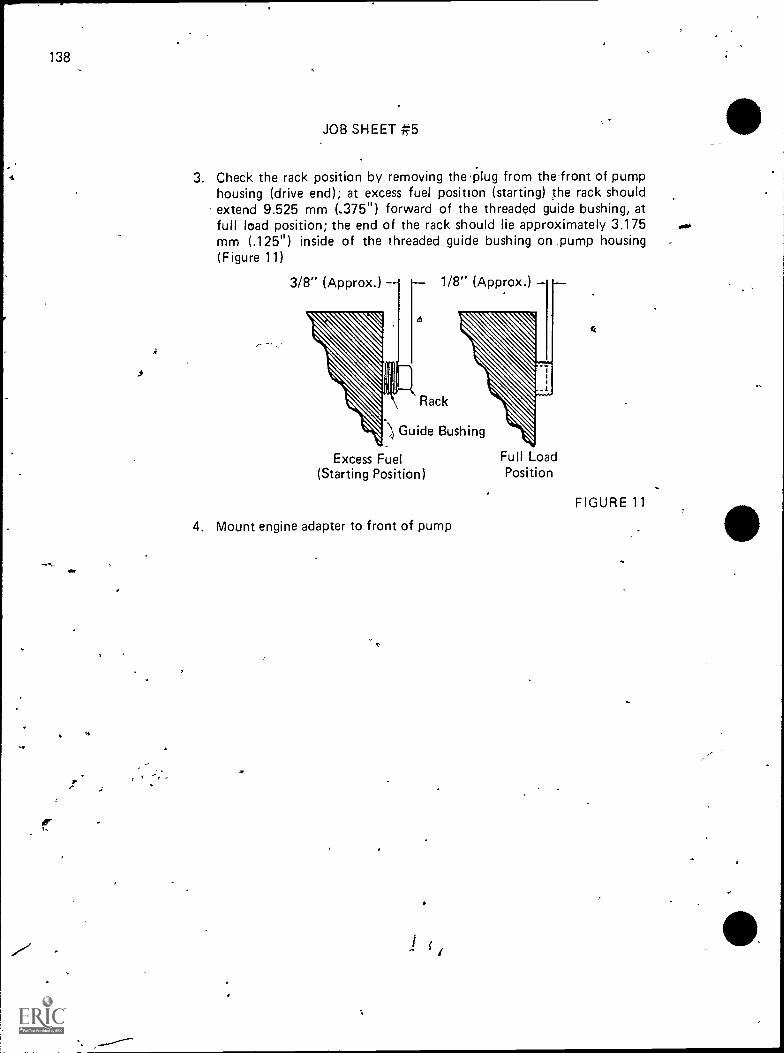
4
er
138
JOB SHEET #5
3. Check the rack position by removing the 'plug from the front of pumphousing (drive end); at excess fuel position (starting) the rack shouldextend 9.525 mm (..375") forward of the threaded guide bushing, atfull load position; the end of the rack should lie approximately 3.175mm (.125") inside of the threaded guide bushing on pump housing(Figure 11)
3/8" (Approx.) 1/8" (Approx.)
Rack
Guide Bushing
Excess Fuel(Starting Position)
4. Mount engine adapter to front of pump
f
Full LoadPosition
FIGURE 11

D:FS-139
IN-LINE INJECTION PUMPUNIT IV
JOB SHEET #6--BENCH TEST AN IN-LINE PUMP
I. Tools and materials
A. Basic hand tool set
B. ApRsopriate service manual
C. Test stand adapters
D. Test stand manual
E. Pump tools
F. Special tools
G. Pump specification sheet
H. Clean shop towels (lint-free)
I. Safety glasses
II. Procedure
(CAUTION: Follow all shop safety procedures.)
A. Use the appropriate manual for the pump you are working on and followthe procedure outlined in it
B. Use the following chart and fill in the appropriate blanks when testingthe pump
(
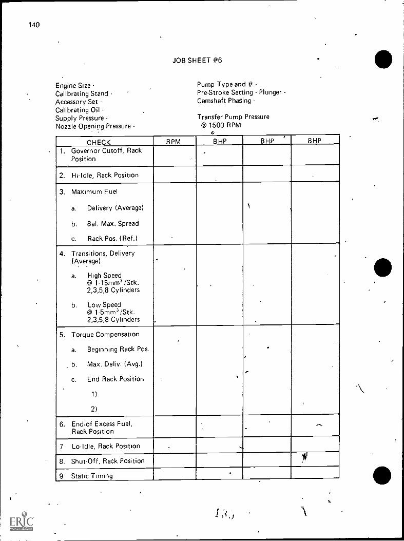
140
Engine SizeCalibrating StandAccessory SetCalibrating OilSupply PressureNozzle Opening Pressure
JOB SHEET #6
Pump Type and #Pre-Stroke Setting Plunger -Camshaft Phating
Transfer Pump Pressure@ 1500 RPM
CHECK RPM BHP BHP,
BHP
1. Governor Cutoff, RackPosition .
.
,
2. Hi-Idle, Rack Position
3. Maximum Fuel
a. Delivery (Average)
b. Bal. Max. Spread
c. Rack Pos. (Ref.)
1%
4. Transitions, Delivery(Average)
a. High Speed@ 1-15mm3/Stk.2,3,5,8 Cylinders
b. Low Speed@ 1-5mm3/Stk.2,3,5,8 Cylinders
.
,
_
,
5.
,
Torque Compensation
a. Beginning Rack Pos.
b. Max. Deliv. (Avg.)
c. End Rack Position
1)
2)
,
,
.
-
.
6. End,of Excess Fuel,Rack Position
.....
7 Lo-Idle, Rack Position , -.....
8. Shut-Off, Rack Position IV
Static Timing,.
1 2`i,
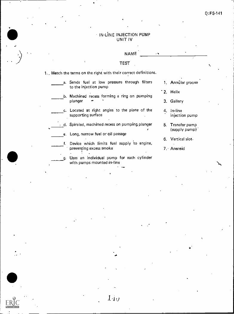
_
IN-L1NE INJECTION PUMPUNIT IV
NAME
TEST
1._ Match the terms on the right with their correct definitions.
a. Sends fuel at low pressure through filtersto the injection pump
b. Machined recess forming a ring on pumpingplunger
c. Located at right angles to the plane of thesupporting surface
d. Spiraled, machined recess on pumping, plunger
e. Long, narrow fuel or oil passage
f. Device which limits fuel supply 'to engine,preventing excess smoke-
g. Uses an individual pump for each cylinderwith pumps mounted-in-line
/6
,
D:FS-141
,
%
1. Anrallar groove
2. Helix
3. Gallery
4. In-lineinjection pump
5. Transfer pump(supply pump)
6. Vertical slot-
7. Aneroid
w
.
\

142
2. Match the main parts of an .in-line pump with their correct names by placing thecorrect numbers in the aripropriate blanks*.
2.
1 I
11110111111111
9. 8.
5.
-1
AM
a. Control rack g. Hand primer
b. Governor h. Injection line
c. Sediment bowl i. Pump housing
d. Aneroid j. Leak-off line
e. Fuel transfer pump k. Camshaft
f. Individual pumping element
3. Arrange in order the steps in which fuel flows from supply tank to delivery by placingthe correct sequence number in the appropriate blank.
a. Pumping element meters fuel at high pressure to each injection nozzlefor delivery to combustion chamber
b. Transfer pump forces fuel under low pressure through secondary filterand through final stage filter to each injection jiumping element
c. Fuel is drawn from supply tank through primary filter by fuel transferpump
-
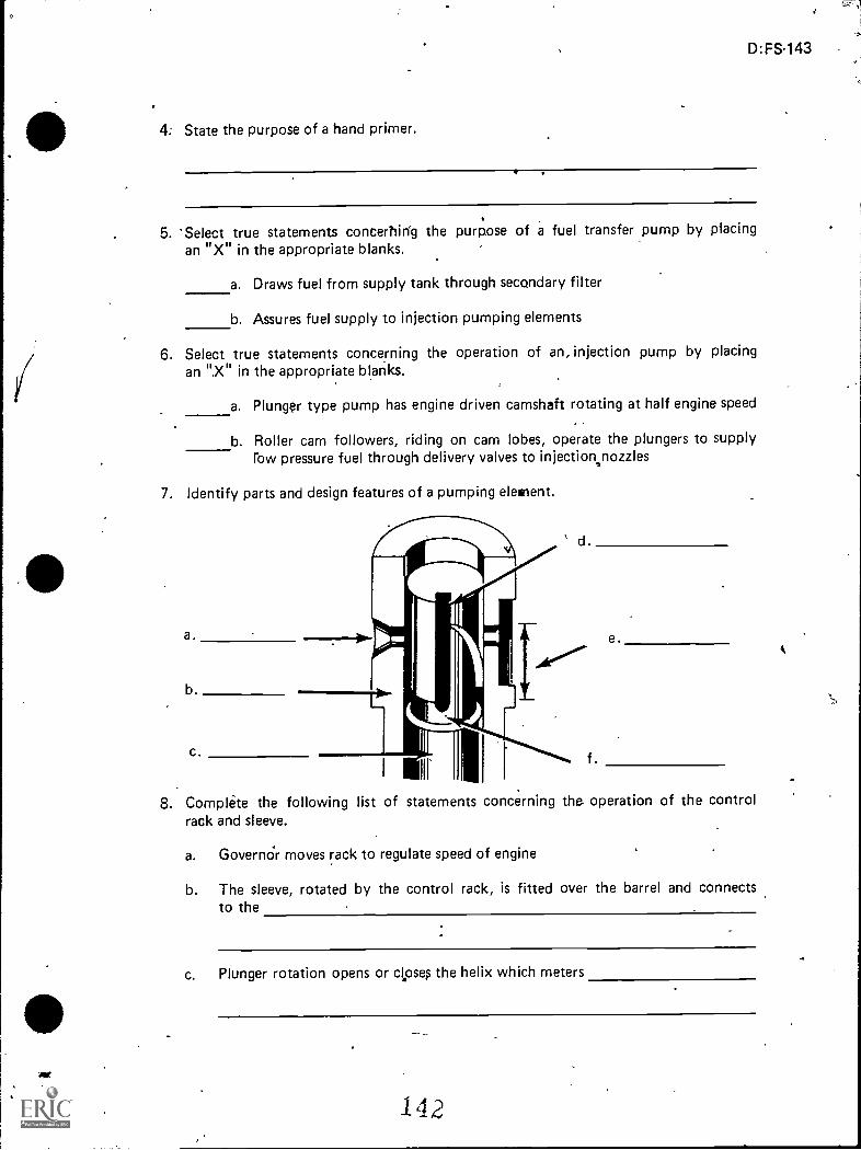
D:FS-143
4. State the purpose of a hand primer.
5. 'Select true statements concerhirfg the purpose of a fuel transfer pump by placing
an "X" in the appropriate blanks.
a. Draws fuel from supply tank through secondary filter
b. Assures fuel supply to injection pumping elements
6. Select true statements concerning the operation of an, injection pump by placingan ".X" in the appropriate blanks.
a. Plunor type pump has engine driven camshaft rotating at half engine speed
b. Roller cam followers, riding on cam lobes, operate the plungers to supplyrow pressure fuel through delivery valves to injection,nozzles
7. Identify parts and design features of a pumping element.
a.
Ill
d
e.
8. Complete the following list of statements concerning the operation of the controlrack and sleeve.
a. Govern& moves rack to regulate speed of engine
b. The sleeve, rotated by the control rack, is fitted over the barrel and connectsto the
c. Plunger rotation opens or clpses the helix which meters
142

144
>
9. State the Purpose of a delivery valve.
10. Identify the plunger and rack positions.
a. No fuel delivery
b. Partial fuel delivery
c. Maximum fuel delivery
2.
1 4 3
1

11. Identify typical tools used for overhauling an in-line injection pump.
k.
m.
n.
a.
s
h.
d.
=11r---11111=--
i=zig ak.
etr-
di
(J
m.n.
)
A
D.:FS-145
to.4

146
12. Dembinstrate the abiliW,---)
a. Remove an in-line pump.
b. Overhaul an in-line pump,
,
c. Clean and inspect in-line pump components.
d. Reassemble an in-line pump.
e. Reassemble the R.Q.V. governor.
f, Bench test an in-line pump.
(NOTE: If these activities have not been accomplished prior to the test, askyour instructor when they should be completed.)
,?
*.
or
i
r
r

IN-LINE INJECTION PUMPUNIT IV
ANSWER'S TO TEST
1. a. 5 e. 3b. 1 f 7C. 6 g. 4d. 2
2. 'a. 10 e. 8 i. 5b. 11 f. 2 j. ,4c. 7 g. 6 k. 9d. 1 , h. 3
.
3. a. 3b. 2C. 1
4. Hand primer on fuel transfer pump can be operated by hand to pump fuel whenbleeding the system p\
5. b
6. a
7. a. Spill portsb. Barrelc. Plungerd. Vertical slote. Helix.f. Annular groove
8. b. Vanes on the plungdrc. The quantity of fuel for delivery to cylinder
9. The delivery valve creates a sudden pressure drop in the delivery line causing theinjector nozzle valve to close instantly
10. a. 2b. 1
C. ,3
11. a. Remover and installer, barrel plungerb. Wrench, holding, drive flangec. Holder, tappetd. Fixture, pump holdinge. Remover and installer, tappetf. Rack gauge holder9. Gauge, camshaft protrusionh. Wrench, governor spring adjusting
146

148
i. Remover arid installer, governor spring and adjusting screwj. Removpr, governor flyweight damperk. Wrench, tappet adjustingI. Holder, dial indicatorm. Remover and installer, camshaft cylindrical nutn. Dial indicator (inch reading)
12. Performance skills evaluated to the satisfaction of the instructor.
4
/
UNIT INJECTORUNIT V
UNIT OBJECTIVE
D:FS:149.
After completion of this unit, the student shld be able to list functions of a unit injectorand distinguish between no injection and full injection. The student should also be able todemonstrate the ability to disassemble, assemble, test, and install a unit injector. Thisknowledge will be evidenced by correctly performing the procedures outlined in the jobsheets and by scoring 85 percent on the unit test.
SPECI F IC OBJECTIVES
After completion of this unit, the student should be able to:
1. Match terms related to a unit injector with their cOrrect definitions.
2. Match the parts of a unit injector with their correct part names.
3. List functions of a unit injector.
4. Arrange in order the steps in fuel flow through the unit injector fuel system.
5. 'Distinguish between a crown valve and needle valve.
6. Distinguish between no injection and full injection.
7. Demonstrate the ability to:
a. Remove unit injector from engine.
b. Disassemble a unit injector.
c. Assemble a unit injector.
d. Test a unit injector.
e.. Install a unit injector.
4,
148
,
,
,
.%
,

, UNIT INJECTORUNIT V
SUGGESTED ACTIVITIES
I. Provide student with objective sheet.
II. Provide student with information and job sheets.
1th Make transparencies.
IV. Discuss unit and specific objectives.
V. Discuss information sheet.
VI. DemOnstrate and discuss the procedures outlined in the job sheets.
VII. Demonstrate lapping and cleaning procedure's.
VIII. Obtain-a Chart on unit injectors.
IX. Show a film or film strip on unit injectors.
X. Take a field trip to a Detroit Diesel 'dealer.
Xl. Give test.
INSTRUCTIONAL MATERIALS
I. Included in this unit:
A. Objective sheet
B. Information sheet
C. Transparency masters
1. TM 1--Unit Injector
2. TM 2--Parts of Unit Injector (Needle Valve)
3. TM 3--Fuel Flow Through Unit Injector (Crown Valve)
4. TM 4Plunger Positions
D. Job sheets
1. job Sheet #1--Remove Unit Injector from Engine
2. Job Sheet #2--Disassemble a Unit Injector
14 3,
4
P:FS-151

. 152
E.
3. Job Sheet #3Assamble a Unit InjectQL
4. Job Sheet #4Test a Unit Injector
5. Job Sheet #5-lnstall a Unit Injector
Test
F. Answers to test
I I. References:
A. Service Manual, Detroit Diesel Engines. Detroit, MI : betroit Diesel
;1975.
B. Dagel, John F. Diesel Engine Repair. New York: John Wiley and Sons,-Inc., 1982.
C. Foutes, William A. Diesel Engine Mechanics. Stillwat.,:r, OK: Mid-AfnericaVocational Curriculum Consortium, 1977.
L,,s1a4
*11161M111111

,
.............
..
D:FS-153
UNIT INJECTOR,UNIT V
INFORMATION SHEET
I. Terms and zlefinitions
A. Spray valve--Serves as a nozzle to atomize fuel sprayed into combustionchamber
B. Helix-Sraled recess machined into plunger
C. Port--Drilled pass e in bushing
D. Control rack a gear--Rack and pinion gear arrangement on unit injector
E. Bushing-Serves as a barrel for the plunger oh unit injector
F. Unit injector-Injection pump, injector, and spray valve form a single unit(Transparency 1)
(NOTE: One unit is provided for each cylinder.)1
II. Parts of unit injector (Transparency 2)
A. Follower,
B. Follower spring
C. Stop pin
D. Filter cap
- E. Plunger
F. Gasket
,
G. Injector body
H. F ilter
Gear
J. Gear retainer
K. Dowel
L. Control rack
M. Seal
N. Bushing ,
41 _
4
I
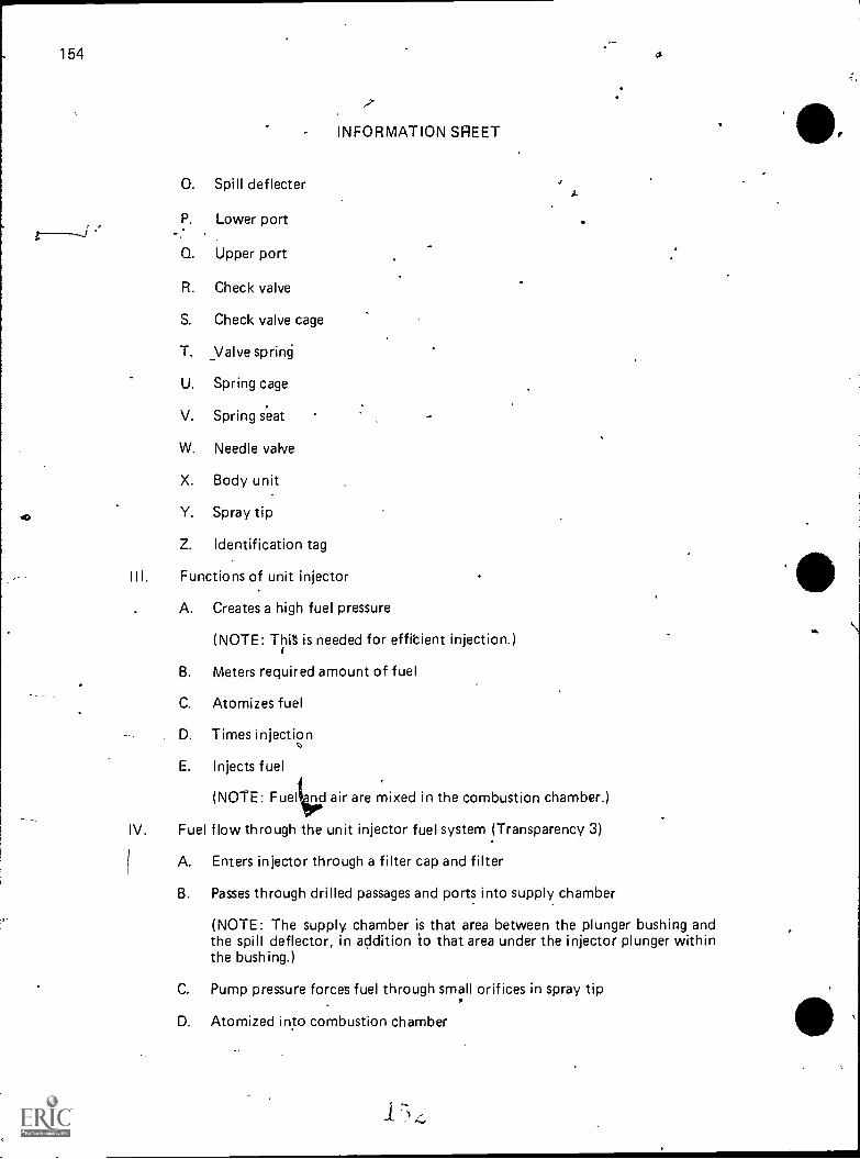
154 a
INFORMATION SHEET
0. Spill deflecter
P. Lower port.
Q. Upper port
R. Check valve
S. Check valve cage
T. _Valve sprin6
U. Spring cage
V. Spring seat
W. Needle valve
X. Body unit
Y. Spray tip
Z. Identification tag
Functions of unit injector
A. Creates a high fuel pressure
(NOTE: This is needed for effibient injection.)
B. Meters required amount of fuel
C. Atomizes fuel
D. Times injection
1
E. Injects fuel
tir(NOTE: Fuel nd air are mixed in the combustion chamber.)
IV. Fuel flow through the unit injector fuel system (Transparency 3)
A. Enters injector through a filter cap and filter
B. Passes through drilled passages and ports into supply chamber
(NOTE: The supply chamber is that area between the plunger bushing andthe spill deflector, in addition io that area under the injector plunger withinthe bushing.)
C. Pump pressure forces fuel through small orifices in spray tip
D. Atomized into combustion chamber
D:FS-155
INFORMATION SHEET
V. Differences between a frown valve and needle valve (Transparencies 2 and 3),
(NOTE: From the bushing up, the design of these valves is the same.)
A. Crown valve
1. Stacked onto the bushing as follows: check valve, valve cage, andvalve seat
2. Inside the valve cage are the valve stop, spring, and injector valve
B. Needle valve
1. Stacked onto the bushing as follows: check v.alve, valve cage, spring,spring seat, spring cage, and spray tip
2. Inside spray tip is the needle valve
3. ...Inside spring cage is the spring seat and the valve spring
V I. Differences between no injection and full injection (Transparency 4)
(NOTE: Changing the position of the helices by rotating the plunger increases ordecreases the amount of fuel injected into the cylinder.)
A. No injection
1. Control rack out
2. Upper port is not closed by helix
,B. Full injection
1. Control rack in
2. Upper port is closed and lower port is closed by helix
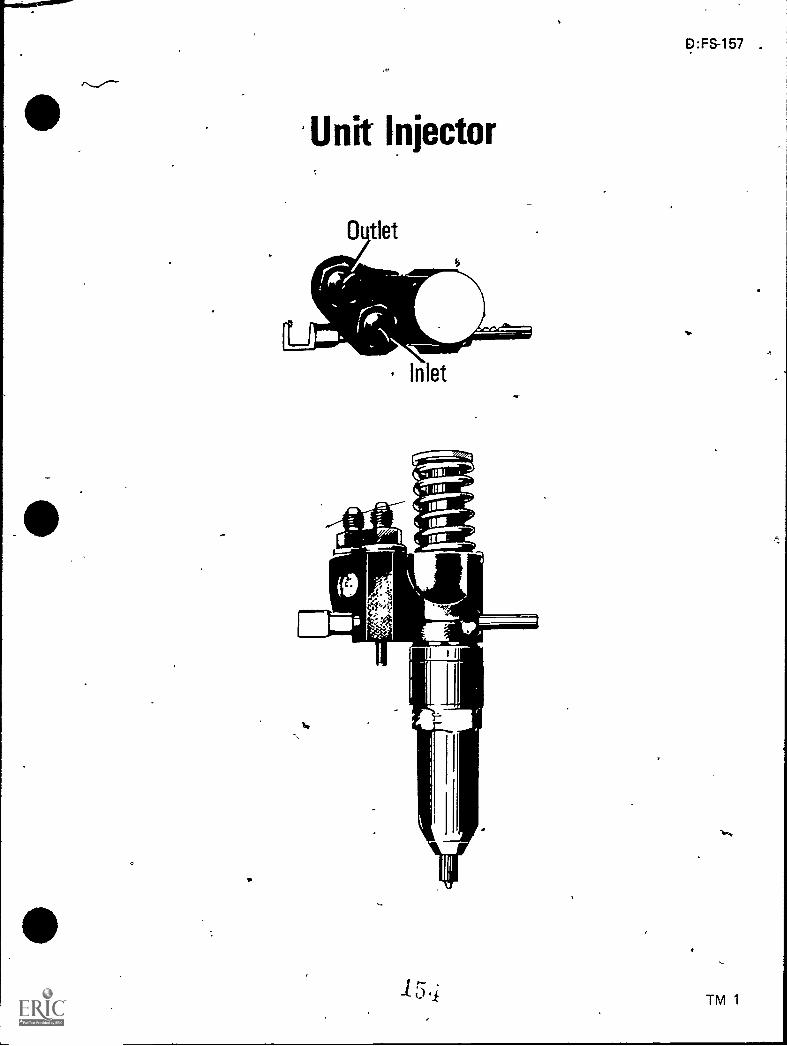
Unit Injector
_05tlet
NiErN-Nr-Inlet
D:FS-157 .
TM 1

Follower Spring
Stop Pin
Plunger
Gear
Gear Retainer
Parts Of Unit InjectorNeedle Valve
Follower
Filter Cali
asket
InjectorBody
FilterBushing
Spill Deflector
Lower Port
Check Valve
Valve Spring
Needle Valve
Spray_Tip_
"*"..."'".
-4-ControlRack
Dowel
Upper Port
Check Valve Cage,
156
Spring Cage
Spring Seat
Metal Identification TagPressed Into Recess InInjector Body
Identification Mark onPlunger
Identification Mark onEnd of Spray Tip
(Note: Fuel injector shown has needle valve installed. See identification tag on injectorbody to determine type injector valve in use. Refer to service manual for correct pro-cedure when reworking crown valve, needle valve, high valve, or conversion kit service.)
156'

Fuel Flow Through Unit InjectorCrown Valve
Check Valve
11/4
(NOTE: From the bushing up, parts on the crown valve and needlevalve are the same. See Transparency 2.)
Injector Valve
Valve Cage
Valve Stop..
D:FS-161
4
"V
TM 3
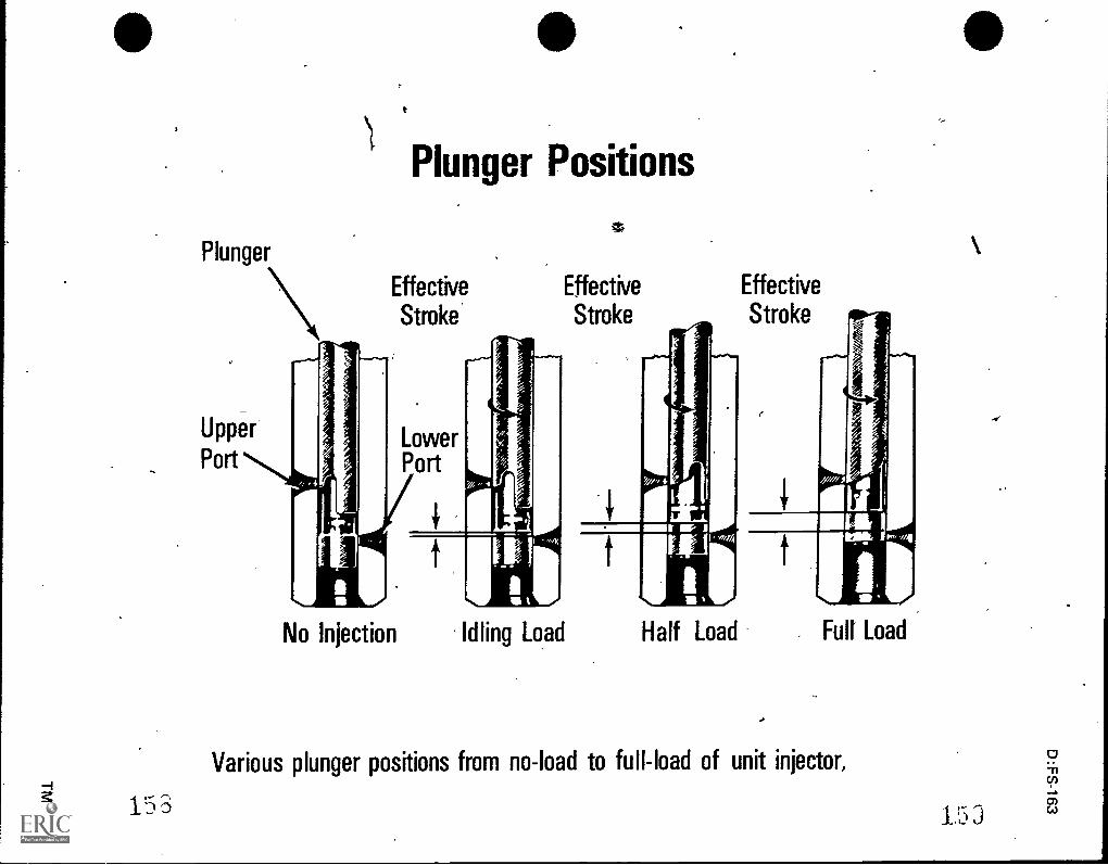
Plunger
Plunger Positions
Effective
Stroke
N o Injection Idling Load
Effective Effective
Stroke Stroke
, writ
H a If Load
Various plunger positions from no-load to full-load of unit injector,
15 3 1.5

D:FS-165
UNIT INJECTORUNIT V
JOB SHEET #1--REMOVE UNIT INJECTOR FROM ENGINE
I. Tools and materials
A. Needle valve fuel injector
B. Appropriate service manual
C. Hand tool set
D. Pry bar
E. Shop towels (lint-free)
F. Safety glasses
II. Procedure
(CAUTION: Follow all shop safety procedures.)
A. Remove the valve rocker cover
B. Remove the fuel pipes from both the injector and the fuel connectors(Figure 1) .
FIGUR-E 1 Injector ,Rocker Arm
Injector Clamp
Dowel Pin
Injector Hole Tube
Fuel Pipes
AF-K_
r (/
Control 'rube
ar/ Rack Control Lever
)
Injectorontrol Rack
(NOTE: Immediately after removal of the fuel pipes from an injector,cover the filter caps with shipping caps to prevent dirt from entering theinjector. Also protect the fuel pipes and fuel connectors from entry, of dirto foreign material.)

166
JOB SHEET #1
C. Rotate the engine to bring the outer ends of the push rods of the injectorand valve rocker arms in line horizontally
D. Remove the two rocker shaft bracket bolts and swing the rocker armsaway from the injector and valves (Figure 2)
FIGURE 2
,
...,
E. Remove the injector clamp bolt, special washer, and clamR
F. Loosen the inner and outer adjusting screws on the injector rack controllever and slide the lever away from the injector
G. Lift the injector from its seat in the cylinder head (Figure 2)
H. Cover fhe injector hole in the cylinder head to keep foreign mpterial out
I. Clean the exterior of the injeCtor with clean fuel oil and dry it with com-.
pressed air

D:FS-167
UNIT INJECTORUNIT V i
JOB SHEET #2--DISASSEMBLE A UNIT INJECTOR
I. Tools and materials
A. Needle valve fuel injector
B. Appropriate service manual
(NOTE: Normally, in industry, unit injectors are pretested before disassem-bly.)
C. Injector nut socket wrench
). Injector spray tip driver
E. Injector vise and rack freeness tester
F. Hand tool set
G. Shop towels (lint-free)
H. Safety glasses
,
/
1

168
II. Procedure
a
JOB SHEET #2
(CAUTION: Follow all shop safety procedures.)
A. Support the injector upright in ifijector vise and rack freeness tester andremove the filter caps, springs, filters, and gaskets (Figure 1)
FIGURE 1
(NOTE: Whenever a fuel injector is disassembled, discard the filters andgaskets and replace with new filters and gaskets.)
(CAUTION: Clean injector before removal and handle with care.)
B. Compress the follower spring and raise the spring above the stop pin with aVscreWdriver and withdraw the pin and allow the spring to rise gradually(Figure 2)
FIGURE 2
Screwdriver
1
6..

.4011
D:FS-1,69
JOB SHEET #2
C. Remove the plunger follower, plunger, and spring as an assembly (Figure3)
FIG
D. Invert the fixture and, using injector nut socket wrench, loosen the nut onthe injector body (Figure 4)
-FIGURE 4
E. Lift the injector nut straight up, being careful not to dislodge the spray tipand valve.parts

_.
(
.
170
,
_
4
c
.
-
c
, JOB SHEET #2:.
F. Remove the spray tip and valve parts from the bushing and place them .in a clean receptacle until rieady for assembly
(NOTE: When an injector has been in use .for some time, the spray tip,even though clean on the .outside, may not be pushed readily from thenut with the fingers.. In this event, support the nut on a wood block anddrive the tip down through the nut, using the injector sprey tip driver. SeeFigure 5.)
N. v.
FIGURE 5
,,
..
-

D:FS-171
JOB §HEET #2
G. Remove the spill deflector and the seal ring from the injector nut (Figure 6)
FIGURE 6
) Seal Ring
Spray Tip
Nut
Spill Deflector
L-01(--- Check ValveValve Cage
ValveValve Stop
4,2,C446..Injector ValveValve Seat
Bushing
Gear Retainer
Control Rack
Injector Body
H. Remove the plunger bushing, gear retainer, and gear from the injectorbody
I. Withdraw the injector control rack from,the injector body

e. r
. D:FS-173
1141,,,
UNIT INJECTORUNIT V
JOB SHEET #3--ASSEMBLE A UNIT INJECTOR
I. Tools and materials
A. Needle valve fuel injector
B. Apptopriate service manual
C. Injector vise and rack freeness tester
D. Injector nut socket wrench
E. Deep well socket, 9/16"
F. Torque wrench
G. Hand tool set
H. Fuel oilor calibrating oil
I. Shop towels (lint-free)
J. Safety glasses
K. Clean bench
I

174
JOB StlEET #3
II. Procedure
(CAUTION: Follow all shop safety procedures.)
A. Assemble injector filters
(NOTE: Use an extremely clean bench to work on and to place parts whenassembling an injector. Also, be sure all injector parts, both new and used,are clean. Flush parts in fuel oil or calibrating oil during assembly.)
1. Study relative position of injector parts (Figures 1 acc\I 2)
FIGURE 1
Filter Cap
Gasket
Injector Body
ArWieft.
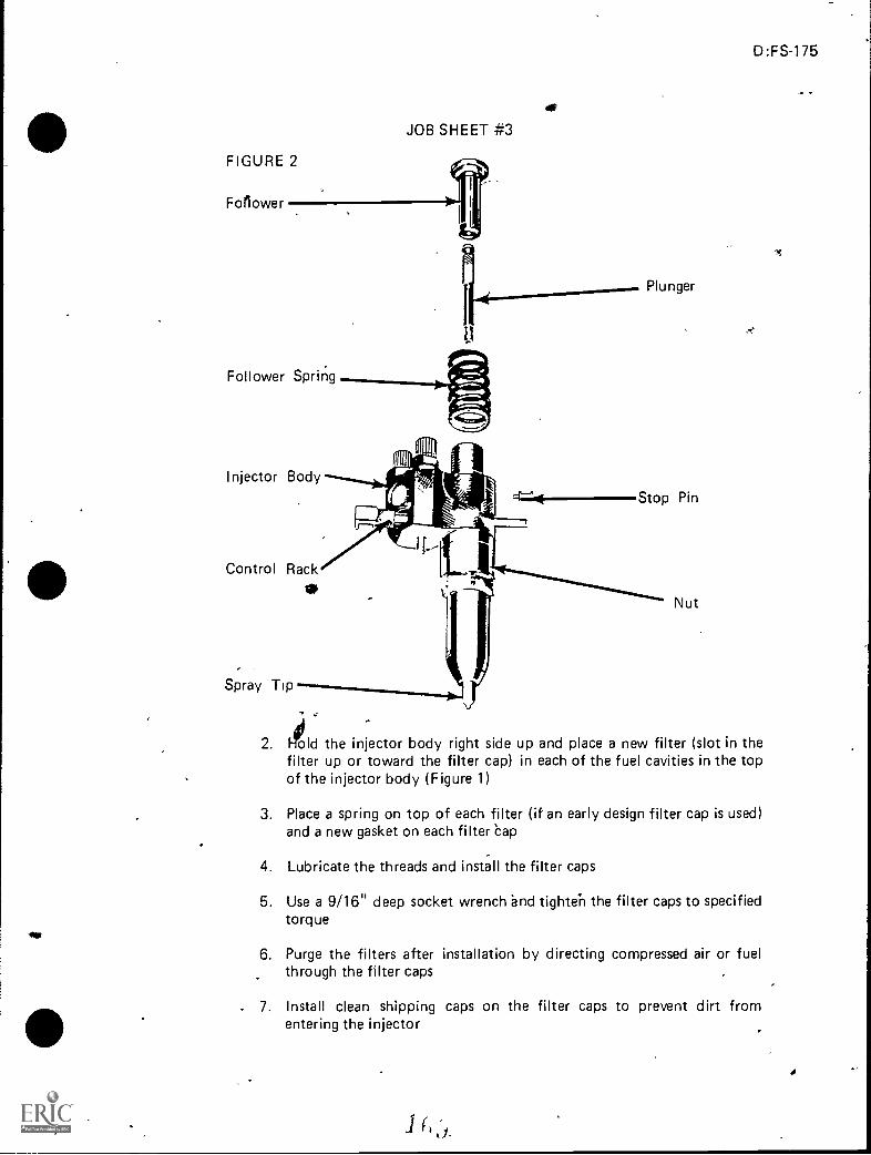
D:FS-175
...
FIGURE 2
For lower
JOB SHEET #3
Follower Spring
Injector Body
Control Rack0
Spray Tip
Plunger
Stop Pin
0,
..
Nut
2. II lold the injector body right side up and place a new filter (slot in thefilter up or toward the filter cap) in each of the fuel cavities in the topof the injector body (Figure 1)
3. Place a spring on top of each filter (if an early design filter cap is used)and a new gasket on each filter eap
4. Lubricate the threads and install the filter caps
5. Use a 9/16" deep socket wrench 'and tighte'n the filter caps to specifiedtorque
6. Purge the filters after installation by directing compressed air or fuelthrough the filter caps
7. Install clean shipping caps on the filter caps to prevent dirt fromentering the injector

176
JOB SHEET #3
B. Assemble rack and gear
(NOTE: Observe the drill spot marks (timing marks) on the control rackand gear. See Figure 3.)
FIGURE 3
Seal Ring
Spray Tip
Valve Cage
411
411-,I
Nut
Spill Deflector
Check Valve
Valve Stop
Valve Spring .------49,......_...,4-Valve Seat Injector Valve
GearBushing
(10----Gear Retainer:.0"..,-.0--- Control RaCk
Injector Body
1. Hold the injector body, bottom end up, and slide the rack throughthe hole in the body
2. Look into the bore fpr the rack teeth, then move the rack until you cansee the drill marks and hold the rack in this position
3. Place the gear in the injector body so that the marked tooth is engagedbetween the two marked teeth on the rack

D:FS-177
JOB SHEET #3
4. Place the gear retainer on top of the gear
5. Align the locating pin in the bu with the slot in the injectorbody, then slide the end of the bush. into place
C. Assemble injector valve and related parts
(NOTE: Make sure the injector valve and related parts have been lappedand cleaned. See,Figure 3.)
1. Support_the injector body, bottom end up, in the injector vise andfreeness tester
2. Place a new seal ring on the shoulder of the body, then slide the spilldeflector over the barrel of the bushing
3. Place the valve seat on the end of the bushing and insert the stem of thevalve in one end of the valve spring and the valve stop in the other end
4. Lower the valve cage over this assembly so that the valve stop seats inthe cage and place the valve cage assembly on the valve seat
5. Locate the check valve centrally on the cage and place the spray tipover the check valve and against the valve cage
6. Lubricate the threads in the injector nut and carefully thread thc nuton the injector bodY by hand
(NOTE: Rotate the spray tip between your thumb and first fingerwhile threading the nut on the injector body. See Figure 4.)
i
FIGURE 4
I ri

178
JOB SHEET #3
7. Tighten the nut as tight as possible by hand
(NOTE: At this point there should be sufficient force on the spray tipto make it impossible to turn with your fingers.)
8. Use injector nut socket wrench and torque wrench to tighten theinjector nut to specified torque (Figure 5)
(NOTE: Do not exceed the specified torque; otherwise, the nut maybe-"Stretched and result in improper sealing of the lapped surfacesin a subsequent injector overhaul. Avoid cross threading the nut duringinstallation.)
FIGURE 5
D. Assemble plunger and follower
1. Slide the' head of the plunger into the follower (Figure 2)
2. Invert the injector in the assembly fixture (filter cap end up) and pushthe rack all the way in; then place the follower spring on the injectorbody
3. Place the stop pin on the injector body so that the follower spring restson the narrow flange of the stop pin
4. Align the slot in the follower with the stop pin hole in the injectorbody
5. Align the flat side of the plunger with the slot in the follower
6. Insert the free end of the plunger into the injector body

)
.1
JOB SHEET #3
D:FS-179
7. Press down on the follower and at the same time press the stop pin into,position (Figure 6)
ir
(NOTE: When in place, the spring will hold the stop pin in position.)
FIGURE 6
.7----,
s?

D:FS-181
UNIT INJECTORUNIT V
JOB SHEET #4--TEST A UNIT INJECTOR
I. Tools and materials
A. Needle valve fuel injector
, B. Appropriate servke manual
C. Hand tool set
D. Injector vise and rack freeness tester
E. Injector tester
F. /Comparator injector tester or appropriate calibrator injector tester
G. Shop towels (lint-free)
H. Safety glasses
II. Procedure
(CAUTION: Follow all sBop safety procedures.)
ATE: Identify each injector and record the pressure drop and fuel outputas indicated by the following tests.)
A. Test injector control rack and plunger movement
1. Place the injector in the injector vise and rack freeness tester

182
JOB SHEET #4
2. Place the handle on top of the injector folloWer (Figure 1)
FIGURE 1
.dr
(NOTE: If necessary, adjust the contact screw in the handle to insurethe contact screw is at the center of the follower when the followerspring is compressed.)
3. Hold the injectoccontrol rack in the no-fuel position and push thehandle clown and depress the follower to the bottom of its stroke
4. Release the pressure on the handle very slowly while moving thecontrol rack up and down until the follower reaches the top of its travel(Figure 1)
(NOTE: If the rack does not fall freely, loosen the injector nut, turnthe tip, then retighten the nut. Loosen and retighten the nut a coupleof times if necessary. Generally this will free the rack. Then, if the rackisn't free, change the injector nut. In some cases ACTay be necessary todisassemble the injector to eliminate the cause of the misaligned parts.)
B. lest injector valve opening pressure
(NOTE: The pufpose of the valve opening pressure test is to determinethe pressure at which the valve opens and injection begins.)
1. Place the injector in the tester with the dowel on the underside of theinjector located in the proper slot of the adaptor plate
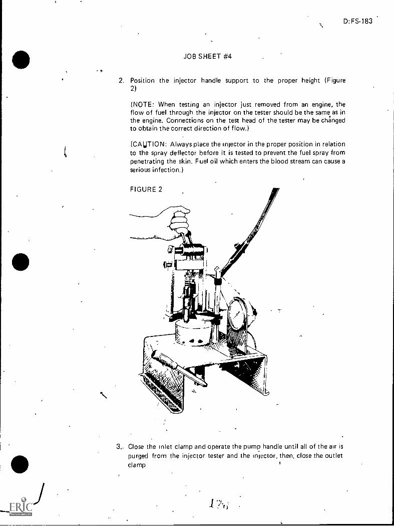
D:FS-183
JOB SHEET #4
2. Position the injector handle support to the proper height (Figure2)
(NOTE: When testing an injector just removed from an engine, theflow of fuel through the injector on the tester should be the same as inthe engine. Connections on the test head of the tester may be changedto obtain the correct direction of flow.)
(CAUTION: Always place the injector in the proper position in relationto the spray deflector before it is tested to prevent the fuel spray frompenetrating the skin. Fuel oil which enters the blood stream can cause aserious infection.)
3. Close the inlet clamp and operate the pump handle until all of the air ispurged from the injector tester and the injector, then, close the outletclamp

184
A
JOB SHEET #4
4. With the injector rack in the full-fuel position, pump the handle of theinjector tester with smooth, even strokes and record the injector valveoperUng pressure indicated when the injector sprays fuel (Figure 3)
FIGURE 3
(NOTE: The specified valve opening pressure is 450 to 850 psi. Ifthe pressure is not within the above range, refer to manufacturer'stroubleshooting chart.)
C. Perform injector valve holding pressure test
(NOTE: The injector valve holding pressure test will determine whetherthe various lapped surfaces in the injector are sealing properly.)
1. Operate the pump handle to bring the (pressure up t point justbelow the injector valve opening pressui'a.. ately 450 psi)
2. Close the fuel shut off valve and note the pressure drop'_
(NOTE. The time for a pressure drop from 450 psi to 250 psi should,not be less than 40 seconds. If the pressure drop is less than 40 seconds,follow procedures a through c.)
D:FS-185
JOB SHEET #4
a. Dry the injector thoroughly with compressed air
b. Open the tester fuel valve and operate the pump handle to main-tain the test pressure
c. Correct malfunctions as appropriate
1) 'A leak around the spray tip or seal ring usually is caused by aloose injector nut, a damaged seal ring, or hardened surfaceon theinjector nut or spray tip
2) A leak at the filter cap indicates a loose filter cap or damagedfilter cap gasket
3) A "dribble" at the spray tip orifices indicates a leaking valveassembly due to a damaded surface or dirt; leakage at the tipwill catise pre-ignition in the engine
(NOTE: A drop or two of fuel at the spray tip is only anindication of the fuel trapped in the spray tip at the begin-ning of the test and is not detrimental as long as the pressuredrop specified is not less than 40 seconds.)
D. Perform injector high pressure test
(NOTE: This test is performed to discover any fuel leaks at the injector filtercap gaskets, body plugs and nut seal ring which did not appear during thevalve holding pressure test. The high pressure test also indicates whether ornot-the plunger and bushing clearance is satisfactory.)
1. Thoroughly dry the injector with compressed air
2. Check the fuel connections for leaks; if leaks have occurred, tighten the'connections, dry the injector, and recheck
d>
a

186
JOB SHEET
3. With the injector rack in the futl-fuet position and the injector testerhandle locked in position by means of the harrdle lock, operate thepump handle to build up and maintam the pressure (Figure 4)
FIGURE 4
4. Use the adjusting screvy in the injector tester handle to depress theinjector plunger just far enough to close both ports in the injectorbushing
(NOTE: The point at which bo`th ports are closed may be easily ascer-tained by the fact that the injector spray will decrease appreciably and
--'a rise in pressure will occur. At this time, the condition of the plungerand bushing may be established If there is excessive clearance betweenthe plunger and bushing, pressure beyond the normal valve openingpressure cannot be obtained. Replacement of the plumger and bushingassembly is then required.)
5. Pump up the injector tester and maintain a pressure of 1600 to 2000psi by actuating the pump hantile, then inspect for leaks at the injectorfilter cap gaskets, bo4 plugs, and injector nut seal ring
,
(NOTE: If any of these ,conditions exist, refer to manufacturer's-troubleshooting chart. It is normal for fuel to seep out around the rad<due to high pressure fuel being apphed to a normally low pressure areain the injector assembly. However, fuel droplets at the rack indicateexcessive leakage.) ,
(CAUTION. Do not permit the proYmN, In r (-tor teister to equalor exceed the capacity of the pressur,. gauge )

s
4
,
JOB SHEET #4
E. Test spray pattern
D:FS-187
1"..,1. Open the fuel shut-off valve, .place the injector rack in the full-fuel
position, and operate the injector several times in succession by operat-ing the tester handle at approximately 40 strokes per minute
2. Observe the spray pattern to see that all spray orifices are open andinjecting evenly
(NOTE: The beginning and ending of injection should be sharp andthe fuel injected should be finely atomized. See Figure 4.)
-VI
3. If all of the spray tip.orifices'ife not open and injecting evenly, cleanthe orifices in the spray tip
(CAUTION: To prevent damage to the pressure gauge, do not exceedoft 100 psi during this test.) .
F. Test fuel output
(NOTE: The injector fuel output test can be performed in either the com-parator J 7041 or the calibritor J 22410. See Figures 5 and 6.)
(CAUTION: When injectors are removed from an engine for fuel outputtesting and, if satisfactory, reinstalled without disassembly, extreme careshould be taken to avoid reversing the fuel flow. When the fuel flow isreversed, dirt trapped by the filter is back-flushed into the injector compon-ents.)"
,
)
*
,
4,
I.

188
-
f JOB SHEET -T-s--4
(NOTE Before removing an injector from the engine, observe the directionof the f ueI flow. To avoid reversing tne tuel flow when checking injector fuel
output, use the apprcpriate adaptor The position of the fuel flow pipes onthe comparator depends on the adaptor being used and the direction of fuel
- flow through the injector See Figure 5 The position of the bra,ded fuelinlet tube and the (.1 astic fuel outlet f.ube on the 'calibrator depends on theadaptor being used a,'id the direction of fuel flow through the injecto7 See
Figure 6:,)
FIGURE 5
(
Vial Changer";
Vial^ Fuel FlowStart Button
-1-
7 ct
Off-On
FIGURE 6
Adaptor
Calibrat,Jr
if
Seat
,
InjectorClamp-upValve
Stroke Counter1
AdaptOr
Wheel
,
n'd
4
si
'I
t
8
,
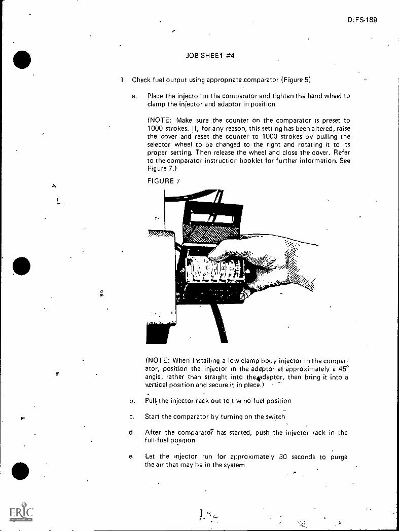
D:FS-189
JOB SHEET #4
1. Check fuel output using appropriate.comparator (Figure 5)
a. Place the injector in the comparator and tighten the hand wheel toclamp the injector and adaptor in position
(NOTE: Make sure the counter on the comparator is preset to1000 strokes. lf, for any reason, this setting has been altered, raisethe cover and reset the counter to 1000 strokes by pulling theselector wheel to be changed to the right and rotating it to itsproper setting. Then release the wheel and close the cover. Referto the comparator instruction booklet for further information. SeeFigure 7.)
FIGURE 7
(NOTE: When installing a low clamp body injector in the compar-ator, position the injector in the adaptor at approximately a 45°angle, rather than straight into the4adaptor, then bring it into avertical position and secure it in place.)
b. Pull..the injector rack out to the no-fuel position
c. Start the comparator by turning on the switch
d. After the comparato7 has started, push the injector rack in thefullfuel position
e. Let the injector run foe- approximately 30 seconds to purgethe air that may be in the system

190
1,4
JOB SHEET #4
f. After 30 seconds, press the fuel flow start button
(NOTE: This will start the flow of fuel into the vial. The compard:tor will automatically stop the flow of fuel after 1000 strokes.)
g. After the fuel stops flowing into the vial, pull the injector rack outto the no-fuel position
h. Turn the comparator off and reset-the counter
i. Observe the reading on the vial and refer to f igure 8 to determineif the injector fuel output falls within its specified limits
(NOTE: If the quantity of fuel in the vial does not fall within thespecified limits, refer to manufacturer's troubleshooting chart forcause and remedy.)
FIGURE 8
IniectorCalibrator1 22410
Comparator1 7041
Min Max Mm Mox
5S8 50 54 9 15
658 53 57 10 16
555 55 59 14 20
S60 59 63 18 24
565 64 68 24 30
570 71 75 30 36
580 80 84 38 AA
. 590 8-7 92 46 52
2. Check fuel output using appropriate calibrator (Figure 6)
a. Place the cam shift index wheel and fuel flow lever in their respec-tive positions
b. Turn on the test fuel oil heater switch.and preheat the test oil to95° to 105°F
c. Place the proper injector adaptor between the tie rods and engageit with the fuel block locating pin
d. Slisle the adaptor forward and up against the fuel block face
e. Place the injector seat into the permanent seat tc,radle handle invertical position)
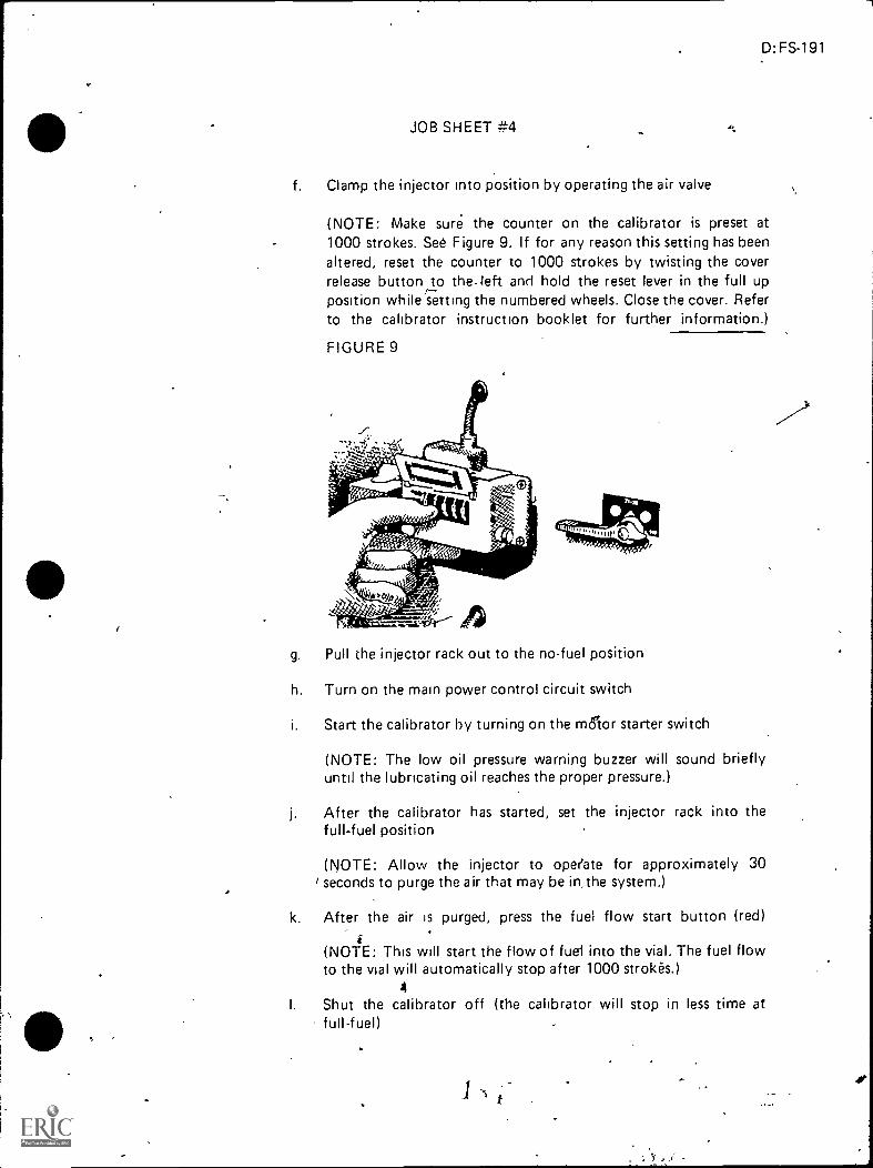
D:FS-191
JOB SHEET #4
f. Clamp the injector into position by operating the air valve
(NOTE: Make sure. the counter on the calibrator is preset at1000 strokes. See Figure 9. If for any reason this setting has beenaltered, reset the counter to 1000 strokes by twisting the coverrelease button to the-left and hold the reset lever in the full upposition while setting the numbered wheels. Close the cover. Referto the calibrator instruction booklet for further information.)
FIGURE 9
g. Pull the injector rack out to the no-fuel position
h. Turn on the main power control circuit switch
i. Start the calibrator by turning on the minor starter switch
(NOTE: The low oil pressure warning buzzer will sound brieflyuntil the lubncating oil reaches the proper pressure.)
After the calibrator has started, set the injector rack into thefull-fuel position
(NOTE: Allow the injector to operate for approximately 30/ seconds to purge the air that may be in, the system.)
k. After the air is purged, press the fuel flow start button (red)i
(NOTE: This will start the flow of fuel into the vial. The fuel flowto the vial will automatically stop after 1000 strolees.)
4
I. Shut the calibrator off (the calibrator will stop in less time atfull-fuel)
, .1. 4, i
192
JOB SHEET .7.4
m. Observe the vial reading and refer to Figure 8 to determinewhether the injector fuel output falls within the specified I pnts
(NOTE: If the quantity of fuel in the vial does not fall within thespecified limits, refer to manufacturer's troubleshooting chart forthe cause and remedy.)
(NOTE: The comparator or the calibrator may be used to checkand select a set of injectors which will inject the same amount offuel in each cylinder at a given throttle setting, thus resulting in asmooth running, well balanced engine An Injector which passes allof the above tests may be put back into service. However, aninjector which fails to pass one or more of the tests must berebuilt and checked on the comparator or the calibrator Anyinjector which is disassembled and rebuilt must be tested againbefore being placed in service.)
-1

UNIT INJECTORUN IT
JOB SHEET #5--INSTALL A UNIT INJECTOR
I. Tools and materials
A. Needle valve fuel injector
B. Appropriate service manual
C. Hand tool set
D. Injector tube bevel reamer
E. Fuel pipe socket
,
4
F. Torque wrench
G. Grease
H. Shop towels (lint-free)
I. Safety glasses
N
...
4.,
,
)
A
D:FS-193

194
e
II. Procedure
A
_
JOB SHEET #5
(CAUT ION Follow al.l shop safety procedures.)
...
(NOTE: Before installing an injector in an engine, remove the carbon deposits,from the beveled seat of the injector tube in the cylinder head. This will assurecorrect alignment of the injector and prevent any undue stress from being exertedagainst the spray tip.)
A. Use injector tubebevel reamer to clean the carbon from the injector tube(Figure 1)
,
4.
r
er
(CAUTION: Exercise care to remove ONLY' the carbon so that the properclearartce between the injector body and the cylinder head is maintainePack the flutes of the reamer with grease to retain the carbon remo edfrom the tube.)
9(NOTE: Be sure the fuel injector is filled with fuel oil. If necessary, addclean fuel oil at Vie inlet filter cap until it runs out of the outlet filter cap.)
j 1 t
40
A%

i
t.
D:FS-195
JOB SHEET #5
B. Insert the injector into the injector tube with the dowel in the injector !Jodyregistering with the locating hole in the cylinder head (F igure 2)
-FIGURE 2 L1T 110 Rocker Arm
.1-njector Clamp
Dowel Pin
Injector Hole Tube
Injector-
Fuel Pipes
dikarz
704T_I r
,_z_At
' 4 #
Control Tube
Rack Control Lever
Injector,ontrol Rack
Slide the rack control lever over so that it registers with the injector rack-
D. Install the injector clamp, special washer (with curved side toward injectorclamp) and bolt and tighten the bolt to specified torque, making sure thatthe clamp does not interfere with the injector follower spring or the exhaustvalve springs
(NOTE: Check the injector control rack for free movement. Excess torquecan cause the control rack to stick or bind.)
E. Move the rocker arm assembly into posinon and secure Vie rocker armbrackets to the cylinder head by tightening the bolts to the torque specifiedin service manual
(CAUTION: On four valve cylinder heads, there is a possibility of damagingthe exhaust valves if the exhaust valve bridges are not resting on the ends ofthe exhaust valves when tightening the rocker shaft bracket bolts. Therefore,n6te the position of the exhaust valve bridges before, during, and after-tightening the rocker shaft bolts.)
I
'WV

196
JOB SHEET #5
F. Remove the shipping caps; then, install the fuel pipes and connect themto the injector and the fuel connectors, using fuel pipe socket to tighten theconnections/p specified torque
(NOTE: A specified fuel pipe socket may be needed; refer to apprqpriateservice manual.)
(CAUTION: Do not bend the fuel pipes and do not exceed the specifiedtorque. Excessive tijhtening will twist or fracture the flared end of the fuelline and result in leaks. Lubricating oil diluted by fuel oil can cause seriousdamage to the engine bearings.)
G. Refer to service manual for final adjustments and tune-up procedures
"P
aer
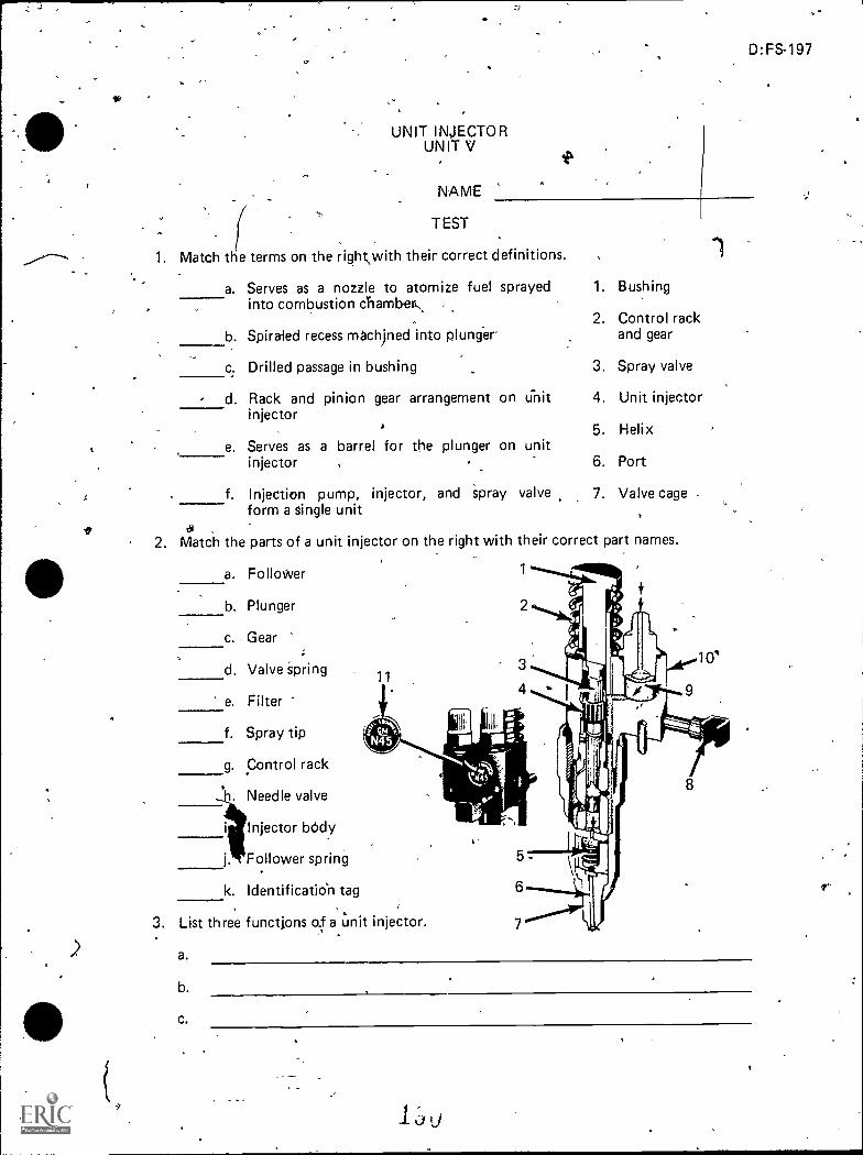
UNIT INJECTORUNIT V
NAME
TEST
D:FS-197
1. Match t e terms on the right,with their correct definitions.
a. Serves as a nozzle to atomize fuel sprayed 1.
into combustion chamber-,
b. Spiraled recess m8chined into plunger'
c. Drilled passage in bushing
d. Rack and pinion gear arrangement on unitinjector
e.
f.
Serves as a barrel for the plunger on unitinjector
Injection pump, injector,form a single unit
and spray valve
Bushing
2. Control rackand gear
3. Spray valve
4. Unit injector
5. Helix
6. Port
7. Valve cage
2. Match the parts of a unit injector on the right with their correct part names.
a. Follower
b. Plunger
c.. Gear
ti. Valve Spring
e. Filter
f. Spray tip
g. Control rack
. Needle valve
i Injector body
j. Follower spring
k. Identificaticin tag
11
3. List three functions of a unit injector.
a.
b.
C.

198
4. Arrange in order the steps in fuel flow through the unit injector,fuel system by placingthe-correct sequence number in the appropriate blank.
a. Passes thrbugh drilled passages and ports into supply chamber
b. Atomized into combuStion chamber
c. Pump pressure forces fuel through small orifices in spray tip
d. Enters injector through a filter cap and filter
5. Dietinguish between a crown valve and needle valve by placing an "X" next to thedesCription of a crown valve.
a. 1)% Stacked onto the bushings as follows: check valve, valVe cage.,
and valve seat
2) Inside valve cage are the valve stop, spring, and injector valve
b. 1) Stacked onto the bushing as follows: check valve,spring, spring seat, spring cage, and spray tip
valve,cage,
2) Inside spray tip is the needle valve
3) Inside spring cage is the sp' ring seat and the valve spring
6. Distinguish between no injection and full injection by placing an "X" next to- thedescriptions of no injection.
a. Control rack out
b. Control rack in
c. Upper port is not closed by helix
d. Upper port is closed and lower port is closed by helix.
7. Demonstrate the ability to:
a. Remove unit injector from engine.
b. Disassemble a unit injector.
c. Assemble a unit injector.
d. Test a unit injector.
e. Install a unit injector.
(NOTE . If these activities have not been accomplished prior to the test, ask yourinstructor when they should be Completed.)

UNIT INJECTORUNIT V
ANSWER$TO TEST
,
1. a. 3- d,. 2
C.
56
-e.f.
.
2. a. 1- e. 9b. 3 f. 7c. 4 g. 8d.' h. 6
S.
S.
3**Any three of the following:
a.- Creates a high fuel Pressure-b. Meiers required amount of fuelc. Atomizes the fuel 1,
,d. Times injectiOne. 'Injects
4. a. 2b.' 4C. 3d. .
a,
6. a,c
I. 10j. 2k. 11
7. Performance'skills evaluated to the satisfaction of the instructor-4 ,
47.
h
1 92
11.
D:FS-199
PT FUEL SYSTEMS./..MIT VI
UNIT OBJECTIVE
D:FS.201
After completion of this unit, the student should be able to name the main parts of apressure time (PT) fuel injection system and discuss its operation. The student shouidalso be able to install a PT type pump,-and remove and install PT injectqrs. This knowledgewill be evidenced by correctly performing the procedures outlined in the job sheets and byscoring 85 percent on the unit test.
SPECIFIC OBJECTIVES*"t.
After completion of this unit, the student should be Sble to:
1. Match terms related to PT fuel systems with their correct definitions.
2. Name the three main parts of a PT fuel system.
3. Match the main uniti of a PT pump assembly with their functions.
4
4. Select true statements concerning the operation of a PT injection system.
5. State the function of a pulsation damper.
6. Complete a list of statements concerning the operation of a mechanical governor.
7. Name two types of PT injectors.
8. Match the operational steps of PT injectors with their descriptions.
9. Demonstrate the ability to:
a. Remove and install flange typ*PT injectors. ,
b. Remove and install PT (type B, C, and D) injectors.
c. Adjust an injector plunger and valves using the torque method.
d. Install a PT-R fuel pump and adjust high and low engine idle.
e. Test and adjust a PT-G fuel pump.
f. sAdjust an injector using the dial indicator method.

PT FUEL SYSTEMSUNIT VI
SUGGESTED ACTIVITIES
I. Provide student with objective sheet.
II. Provide student with information and job sheets.
III: Make transparencies.
IV. 'Discuss unit and specific objectives.
V. Discuss information sheet.
VI. Demonstrate and discos the procedures outlined in the job sheets.
VI). Supply the appropriate service manual for the injector you have in yourshop, -
D.FS,203
VIII. Obtain at least 3 types of PT pumps (PT-R, PT-G, AFC) for use in classroomdemonstrations'.
IX.' Show film on PT fuel systems.
X. Give test.
.41
INSTRUCTIONAt MATERIALS
Included in this unit:
A.. Objective sheet
B. Information sheet
C. Transparency masters
1. TM 1-Kain Parts of PT Fuel Sistem
2. TM 2--PT Pump Assembly
3. TM 3--PT Pump Assembly (Continued)
4. TM 4--Types o Injectors
5. TM 5--Operati n of Injectors
6. TM 6--AFC in the "Full Air" Position
7. TM 7--AFC in the "No Air" Position 411,
e
rrr
*
4
1.
"4
. Job_Sheet 41-Remove and inst.:. Flange Type PT iniec..3.
2: 4ob Stieef #2-- Remove and finstalF PT- (Type _13; C, .-,,_i-q D
. . , .3. Job Sheet #3--Adjust an Injectoi'Plunger and Vatvejd.::&;;A:::-Ir -7,.7.6'-6,,,,--
Method .
_
r -
an WC-tr.)
_
s.
4. "Job:Sheettr#4--Instpll a PT-R Fuel Pvmp ond--;Adjusta
.Engine I le,- .
5. JofiStieet #5--Test andAdjust a PT-G Fuel:Pump
6. So6'Sheet #6,---Adjust, an Injector 'Using the
. "_test
F. Aniweit to tdst
,)ieferences: . ,.. _
... . (1
A. Tobolcirr William,K: Diesel Fundamentals, &vice, RePair. South .flolland4-IL: Goodheart-Willcox Cpmpany; frf6., 1980.
B.. K,ptes, Edpr d: arid Lutk,_Willirn E. Dieel ahd High Cbriiprespbn 04 ...,.:.,, ,_ ___ Engines. Third editioncChibago: American-technical iety, 1974:
. _ - . .
-c7
Dial Indicator, Veth6a
rrr
tre
: er.C. 4SerVice BUlletin No. 3379011-01. Iniector P1±_n_gei- and Valve Adjustments..Coluinbus, IN Cummig En-gine-Co:;-Decernb, 1975
e.C.. 4D. Service thilietin No. 3379101-00: PT Fuel Pump Calibration. '01-u-mbas; --.0,--
IN: CuMrnins Engine, Co.. December'," 1975:. . ,
,., .-)'s . ,,
V
gE. Service Bulletin, No. 3379071-Q2: iniecthri, All Types. Coftirribus, IN:Cummint Engine Co.,,. Decernber, 1975.
c._ -9 f:"`,,:
c. ,Serikce Bulletin No., .98372S: Calibration of PT-G ,Pfrimps. Cplurnbue, tCiimmsins-Engine Co., 1975. . _ ' -- - (} .., /"...e . ..
- .. ..G. Service Bulletin No. ,9B.,7535: ale pump _PT Repuilding. ColurnjS)us,IN: "--
-Curnmins-Engine_Co.,1975: 0,- . . 4-f_ ,\ ' .. tc
H. . Service Buile;tihNo. 3379013,402: ;fruel'RumP PT Rebuilding, olumbus, Ik,'Cummins EngineCo 1989.
L.0:- -c5 = C - - aDagel, gohn, F.:Diesel Fngin P, Repair. New -Xork: John Wiley° arid ,Sons,_ ,. .-4 .inc., 1'981 r",',;, . -.
. e ..A
Foutes, Williernolk. -Di6ej;Engihe Mechanics. Stillwater, 'OK. Mid-Arnerica- Vocati nal-CftirriculUm-CasOrtium, 1977,4, ,,..,_4. `
' I ' ' ,. ''

c,
LP
D:FS220t-4
t PT FUEL SYSTEMS, UNIT VI
lt\IFORMATION SHEET
Terms and defininons
A. PT system-Pressure time system based on the,principle that the voltimeof liquid flow is proportionate to the fluid pressure, the time allowed tollow, and the size of the passage rough which the liquid flows
B. PT t\-49e 9-PT fuel pump which is governor controlled
C. PT type R-.PT fuel pump which is pressure regulated
D. Purge--To get rid-of trapped fuel
E. Rated speed-.Engine rpm's under full load
F Meter--To supply inca measured amount
G. High idle or maximum no-load speed--Engine rpm's with no-load and throttlefully open
H. AF --Air fuel ratio control
II. Main part óf PT fuel system (Transparency 1)
A. Fuel ump
.B. SupIy limes, drain lines, and papsages
C.
III. 'Punctions of units of'PT pump assembly (Transparencies 2 and 3)
A. Gear pump--Draws fuel from supply tank forcing it through the pump-filte§creen into the pressure regulator valve
B. Pressure regulator-Limits''the pressure of the fuel to the injectors
C. Thrqttle-Provides a 'manual control of Ipel flow to the injector underall conditions in the operating ran9e
D. Governor assembly,-Controls the flow of fuel from idle to maximum.gover-nor speed
IV, Operation of PT injection system
A. .Gear type' fuel pump delivers fuel through a restricting throttle to ,thegovernor
B. From the governor, the fuel goes to manifold wh.ich feeds cam-operatedinjectorki2 the cylinder head
96
AL-

296
INFORMATION SHEET
C. 'Injector raises pressure to produce a gooa sprayi and times the start ofinjection
V. runction of pulsagri daMper--The damper contains a steel diaphragm= whichabsorbs pUlsatiOns and smooths fuel flow through system (Transparency 2)
(NOTE: The pulsation damper, mounted on gear pump, performs the samefunction onboth type G and type R fuel pumps.)
VI. Operation of mechanical governor (Transparency 3)
A. Between idle and maximum speed, fuel flows through the governor to theinjector in accordance with engine requirements as controlled by the throttle
B. When engine reaches governed speed, the governor weights move the gover-nor plungers so fuel passage to the injectors is shut off
(NOTE: At the same time another passage opens and dumps the fuel back_ into-the noin pump body. The engine speed is controlled and limited regard-
less of the position of the throttle.)
C. Fuel leaving the governor flows through the shut down valve, inlet supplylines, and onto ihe injectors
VII. Types of PT injectors (Transparency 4)
A. Flanged
B. Cylindrical
VIII. Operational seps of PT injectors (Transparency 5)
A, 1Vletering
1. Fuel enters the injector at fuel (inlet,
(NOTE :'Pressure is determined by throttle and/or governor.)
2. Metering orifice -controls quantity of fuel that enters the injector clip..,
)t,(NOTE: Pressure is determined by the fuel pump'and e time interval.during which the hole supplying kref/is uncovered b the injectorplunger.)
B. Injection
i1. Downward plunger movement cuts off fuel entry into injector Cup

D:-FS-207
INFORMATION.SHEET
2. Continued downward movemeni forces fuel from injector cup throughthe orifice into combustion chamber
(NOTE: High pressures allow for almost complete burning of fuelspray.)
3. While plunger is down, fuel passes through upper tiole around undercutin plunger through return passages to the fuel lank
C. Purging
1. Plunger remains seated after injection
(NOTE: Fuel flows through the injector coolin4 it and warming tankfuel through this stage.)
2. Plunger rises on next me,ing operation
(NOTE: The timing of metering and injection is determined by cam-shaft configuration.) .
D. Air fuel ratio control (Transparencies 6 ancl 7)
)1. Made to replace the PT-G,pump and aneroid on turbocharged engines
2. The A.F.C. limits fyel pressure and flow restriction
3. The A.F.C. gives the correct air fuel delivery rate to the engin'e duringacceleration
.ct
sc

.0
Main Pans of PT Fuel SystemCummins
Injector Type 'B' fnjector Type 'C' Injector Type.:Ds, Injector Flanged
I
Fuel ,Purnp Type 'G'
A3-93 Courtesy of Cummins E'ngine Co., Inc.
Fltiel Filter
/////1 10/AAFuel Supply Fuel Suction Fuel Return
0.
Fuel Tank
2+),)
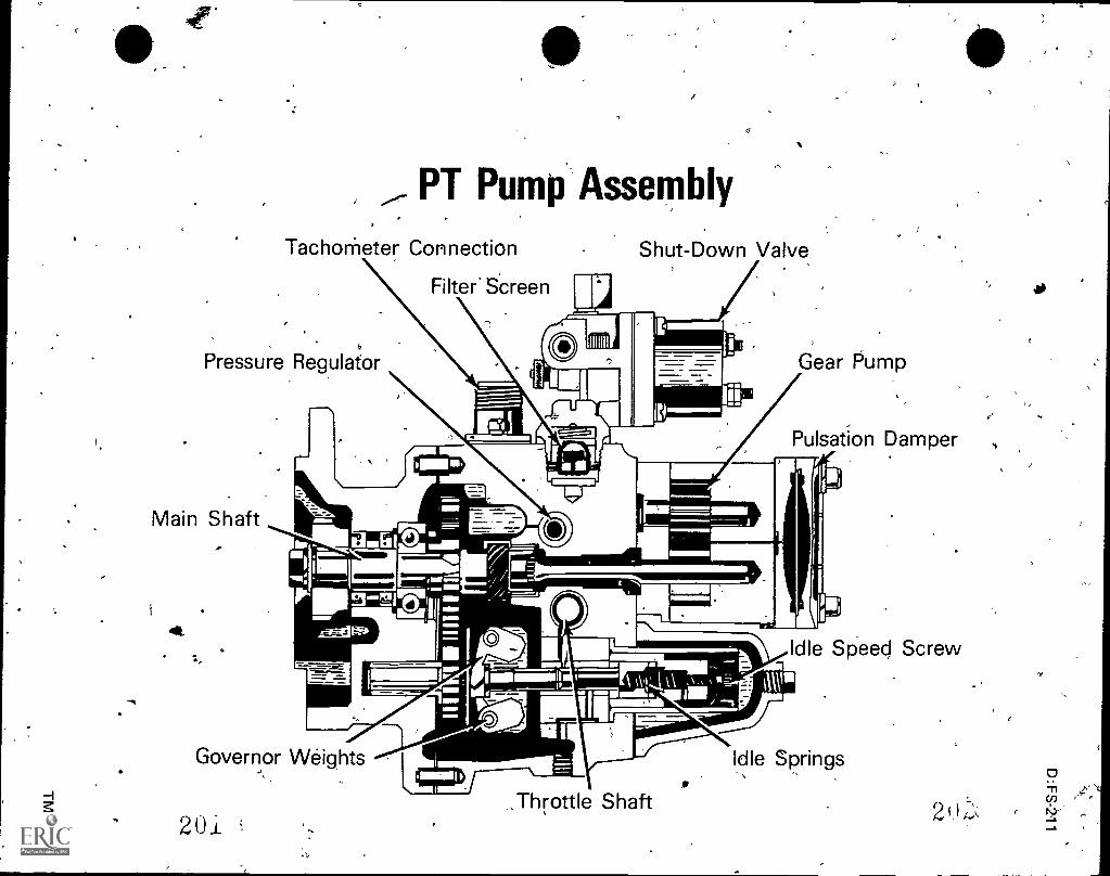
PT Pump Assembly
TachoMeter Connection
Filter SCreen
Shut-Down Valve
Pressure Regulator
Main Shaft
41t.
Gear Pump
Pulsation Damper
Idle Speed Screw
;\ ,\,,
/.a I
Governor Weights
20.1.,Throttle Shaft
Idle Springs

2
e.
7
/-Pump Assenibly
. (Continued) .
To Injectors
Shut=Down.ValveFutl
Filter Screen..
Throttle' Sha
Pulsation Damper
Gear Pump
Pressure Regulator
Governor PlUnger
Governor Weights
CUMMINS PT TYPE R FUEL INJECTION PUMP.
2

,
( - .
,
4
,
,
..
0.
,,
04 Types Of Injectors
, Orifi6.6 Plug
Inlet `Drain
Injector Body
,
Plunger
Injector Spring
"0" Ring Seals
Seal
Gasket
Cup
1
Drain Orifice
'Metering Orifice
-1 FLANGED TYPE INJECTOR4
20j;
.
Injector Link
........L
Plugs
StbpCheck Balt
Fuel Out
Fuel In .
"0" ging Seal
, Plug, Plunger
Metering Orifice
,Cup
,
Adjustable Delivery
;Orifice Plug
-.
.
'0" Ring Seal- ..
Gasket
LYI:INORICALINJECTOR
,
0.
,
2i_h.3
1

a
7
,k411%
::
111111.11.1.1111al
ILIAA
MA
I:\
44
a a
II4
a
mm
Nw
-Aft,
;;;
.tNS \SS \\\\\
"WW
VA
Oais
A'4
a,.....
Al t t ll tt l
1
A.1W
4

* a,
-.,
,
,
s
..
AFC in the "Full Air" Position
$
..,
Ita
Diaphram or Bellows
. Piston
Spring./
Plunger 0-ring Seal
Washer
Fdel Drain Passages
Control Plunger
Fuel Drain Passages
Barrel-O-Ring Seals.,_
Barrel
Fuel Vent to Housing
Air Manifold Pressure,
Plunger Jam Nut
Center Bolt
Sealing Washer
Flat Washer
Fuel to Shutoff Valve
Mounting SpacerPiston Jam Nut
Fuel frornThrottle Shaft
No Air Adjustment Valve ,
No Air Jam Nut
Barrel Spring
,,Throttle COver Plate
,
New Design with the AFC Control Plunger in the "Full Air" Position:
Used,When the ASA is in the Fuel.Courtesy of Cummins Engine Co., Inc.
....._.)
'2 0 :i
,
it
..
.
, 2.10

AFC in the "No Air" Position
Diaphram br Bellows
ft)
Plunger Jam Nut Center Bolt
Sealing Washer
Virilli
Kill .142Ph,
fir---,--.110,"Itri Piston Jam Nut. ,.i eiT i w., ,il --4, Fuel to Shui off ValVe -
eatio
.. ..
,.,r ,,
. d,,,5-,lio tit
*V ;V41 le' /\L 1-7..\
A-----
Piston
Spring
Washer
Plunger 0-Ring Seals
Control Plunger
Fuel Vent to HousingBarrel
Fuel from Thr`ottle Shaft
No Air Adjustment Valve
No Air Jam Nut
Throttle Cover Plate
AFC Top View-Cross Section with thThintrol Plunger in the "No Air': Position.
Used When the ASA Was in the AM Cover.
Courtesy of Cummins Engine Co., Inc.
2 ..i.
.
0cf)
2 1_

oir
OT FUEL SYSTEMSUNIT VI
JOB SHEET #1--REMOVE 'AND INSTALL FLANGE TYPE PT INJECTORS
I. Tools and materials .
A: Basic hand tool set
B. Appropriate service manual
O. Torque wrench
D. Oil can, hand type
E. Shop towels
F. Safety glasses
s,
II. Procedure
(CAUTION: Foll (w all shop safety procedures'.)
P. Remove injector
1. Remove injeCtor hold-down caplcrews
2. Pry and remove injector from cylinderrather than plunger
,
(NOTE: Do not turn "injector/ upsideout.)
3. Place in drain rack
D:FS-223 ,
,head by grasping injector body
down, as plunger might drop
(NOTE: Do not damage injector tip and be careful not to lose theplate retaining collet; do not intermix plunger and injector bodies asthey are paired.)
B. Install injector
1. Clean injector seat With d.lan rag wrapped -around wooden stick
(NOTE: Never use screwdriver or metal tool7for this operation; ascratched seat may causeiimpression leakage.)
2. Position injectors in head(s)
A
(NOTE: When installing injectors in head(s), position injector plunger,so claskinark is Oentered between inlet and drain conhections. Thisprovides the same plunger position under Which the injector was testedin injector test stand. Be careful not to damage ihjector tips.)
21
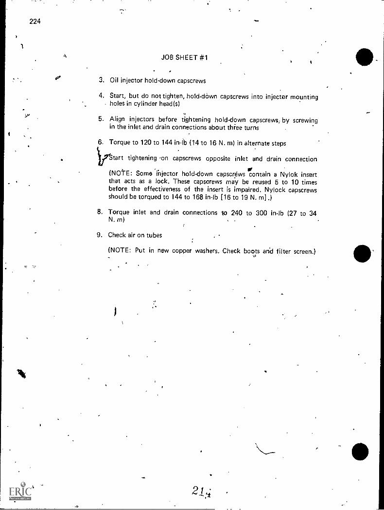
224
to'
A JOB SHEET #1
3. Oil injector hold-down capscrews
4. Start, but do not tighten, hold-down capscrews into injector mountingholes in cylinder head(s)
5. Align injectors before tightening hold-down capscrews., by screwingin the inlet and drain connections about thr'ee turns
6. Torque to 120 to 144 in-lb (14 to 16 N. m) in alternate steps
)ifttart tightening .on capscrews opposite inlet and drain connection
or(NOME: Some 'rnjector hold-down capscrews contain a Nylok insertthat acts as a lock. These capscrews may be reused 5 to 10 timesbefore the effectiveness of the insert is impaired. Nylock capscrewsshould be torqued to 144 to 168 in-lb [16 to 19 N. rn] .)
8. Torque inlet and drain connections to 240 to 300 in-lb (27 to 34N. m)
9. Check air on tubes
(NOTE: Put in new copper washers. Check boots and filter screen.)
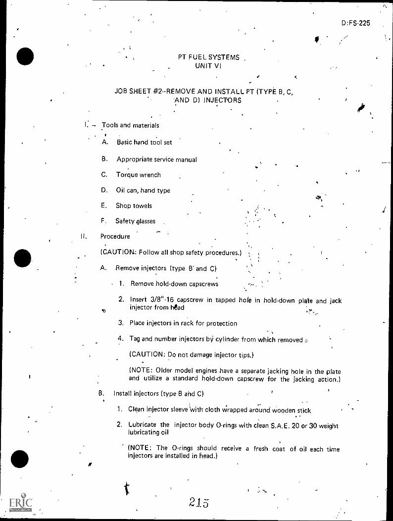
,
;
,
-
PT FUEL SYSTEMS ,
UNIT VI
JOB SHEET #2--REMOVE AND INSTALL PT (TYPE B, C,-AND D) INJECTORS
I: Tools and materials, ,
A. Basic hand tool set
B. Appropriate service manual,
C. Torque wrench
D. Oil can, hand type
E. Shop towels
F. Safety classes
IL Procedure
(CAUTION: Follow all shop safety procedures.) ;
I
A. Remove injectors (type B" and C)
.0
1. Remove hold-down capscrews
,
1
.
f.
-.
i
D:FS-225
2. Insert 3/8"-16 capscrew in tapped hole in hold-down plate and jackinjector from head
3. Place injectors in rack for protection
4. Tag and number injectors by cylinder from which removed,
(CAUTION: Do not damage injector tips.)
(NOTE: Older model engines have a separate jacking hole in the plateand utilize a standard hold-down capscrew for the jacking action.)
B. Install injectors (type B ahd C)
1. Clean injector sleeve 'with cloth wrapped around wooden stick..
2. Lubricate the injector body 0-rings with clean S.A.E. 20 or 30 weightlubricating oil
(NOTE: The 0-rings should receive a fresh coat of oil each timeinjectors are installed in head.)
t215
4 .. '... ,
I
,
..
#41
1
p,
-,i

'JOB SHEET #2
3. Start the injector into bore, guiding by hand until injector is aligned inbore and not bindirt in any manner
(NOTE: To install injectors on V-12 engines, stand either on right bankside or left bank side of engine. On H or NH engines, install injectorsfrom fuel pump side of engine. Injectors are to be placed With ballcheck retainer plug at one o'clock.)
4. Place plastic hammer handle butt on top of injector plunger bodyand "seat" injector by giving a quick, hard push on the hammer
(NOTE: A "snap" should be heard and felt as the cup seats in thecopper sleeve.)
5. Place hold-down plate over injector body with counterbore up
6. Position half-collet locking clamp in injector body groove
7. Start hold-down capscrews, but do not tighten
(NOTE: Be sure the two projecting radii do not drop in drilled holes-atop injector.)
8. Place injector spring on hold-doWn plate with close coil down
(NOTE: Spring must seat on hold-down plate; if spring seats on lockingclamp, irOrrect injector adjustment will result, causing push tube andcamshaffdamage.)
9. Hold injector spring in position and carefully insert injector plunger
,(NOTE: On V-12 engines 'only, position plunger in injector bore withclass mark on the plunger midway between inlet and drain ports ofinjector; the inlet port is below theball retainer plug. This will providethe same operating position in which the injector was calibrated.)
10. Torque procedure for V-12 engines only
a. Make sure injector is positioned correctly in head
b. Tighten one capscrew (use Nylok capscrews) until clamp contactshead snugly; then back out one complete turn
c. Tighten other capscrew to a torque of 48 to 60 in-lb (5 to 7N. m)
d. Tighten firstcapscrew to 84 to 96 in-lb (9 to 11 N. m)
e. Tighten second capscrew to 84 to 96 in-lb (9 to 11 N. m)
2 I O
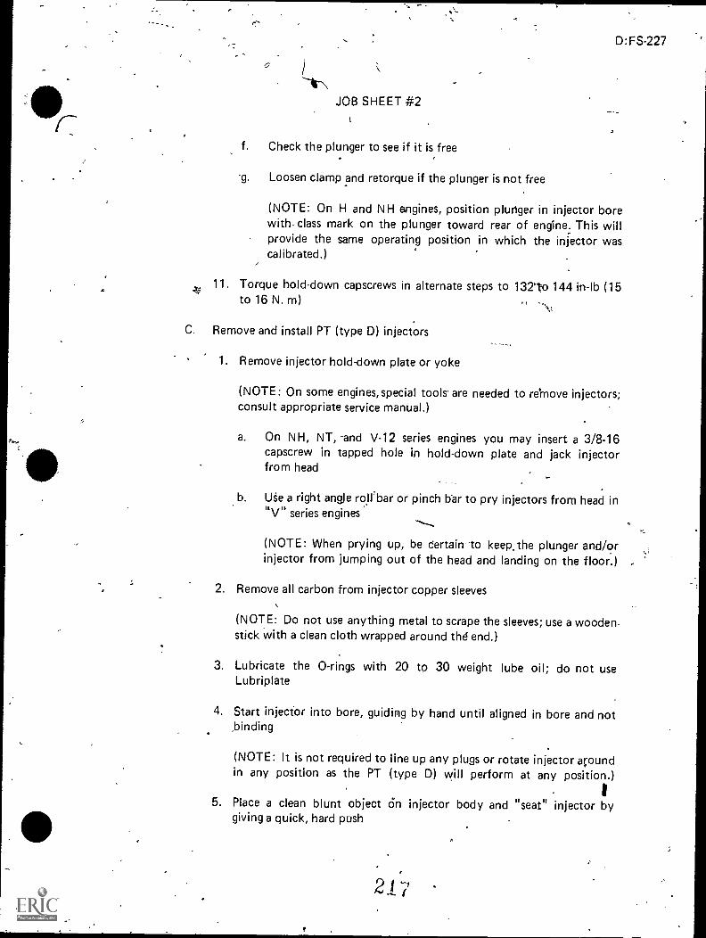
r,
-V
D:FS-227
--
Lir\.,
JOB SHEET #2
i
f. Check the plunger to see if it is free. .
-9. Loosen clamp and retorque if the plunger is not free
(NOTE: On H and NH engines, position plunger in injector borewith, class mark on the plunger toward rear of engine: This willprovide the same operating position in which the injector wascal ibrated.),
11. Torque hold-down capscrews in alternate steps to 13210 144 in-lb (15to 16 N. m) 0 -.
C. Remove and install PT (type D) injectors
1. Remove injector hold-down plate or yoke
(NOTE: On some engines, special tools- are needed to remove injectors;consult appropriate service manual.)
a. On NH, NT, -and V-12 series engines you may insert a 3/8-16
capscrew in tapped hole in hold-down plate and jack injectorfrom head
b. Use a right angle roll/bar or pinch bar to pry injectors from head inRV" series engines
(NOTE: When prying up, be Certain to keep. the plunger and/orinjector from jumping out of the head and landing on the floor.)
2. Remove all carbon from injector copper sleeves,
(NOTE: Do not use anything metal to scrape the sleeves; use a woodenstick with a clean cloth wrapped around thd end.)
3. Lubricate the 0-rings with 20 to 30 weight lube oil; do not useLubriplate
4. Start injecfor into bore, guiding by hand until aligned in bore and not,binding
(NOTE: It is not required to iine up any plugs or rotate injector acoundin any position as the PT (type D) will perform at any position.)
I5. Place a clean blunt object On injector body and "seat" injector by
giving a quick, hard push
f
2.17

228
)
.4
JOB SHEET #2 .
6. Listen for the snap as cup seats in copper sleeve
(NOTE: Do not use a wooden hammer handle or similar tool to install'injectors. Dirt or splinters-from the handle may drop into plunger
link seat causing early failure of link or plunger socket. If injector is notcompletely seated, the 0-rings' may be damaged if pulled down withthe mounting capscrews.) 0Install hold-down plates or yokes, lockwashers, and capscrews
(NOTE: Be certain plates or yokes do not contact crosshead stems.)4
8. Torqqe NH, NT, and KT capscrews in alternate steps to 132 to 144in-lb (15 to 16 N. m)
a. Use Nylok capscrews on V-12 engines and torque alternatelyto 132 to 144 in-lb (15 to 16 N. m)
b. Torque V-6-140, V-8-185, v-378, V-504, V-555, V-8-265 .andV-903 capscrews to 360 to 420 in-lb (41 to 47 N. m)
9. Test injector plunger for movement after torquing hold-down cap-screws. If plunger is not free, loosen and.retorque capscrews
..

D:FS-229
PT FUEL SYSTEMS,UNIT VI
JOB 81-IEET #3--ADJUST AN INJECTOR PLUNGERAND VALVES USING THE TORQUE METHOD
I. Tools -And. materials
A. V-378, V-504, V-555, or VT-555 C.I.D. series Cummins engine
(NOTE: For specific installation and models, refer to the engine manufac-turer's specifications.)
B. Appropriate service manual
C. - Basic hand tool set
D. Inch-pounds torque wrench
E. Foot-poundstorque wrench
F. Feeler gauge
G. Shop towels
,H... Safety glasses
II. Procedure0.
.(CkUTION: Follow all shop safety procedures.)'
, (NOTE: Retorque injector hold-down Clanip capscrews to manufacturer's specifi- ,..,cations before adjusting injectors.)
t) .
A. Position valves'and mark alignment
4
1. Turn drankshaft in direction of rotation until .No. 1-6 "VS" markappears on the vibrationslamper or craRkshaft pulley (Figure 1)
4
(NOTE: Some models may have "A" marked on damper.)
2 9 ,
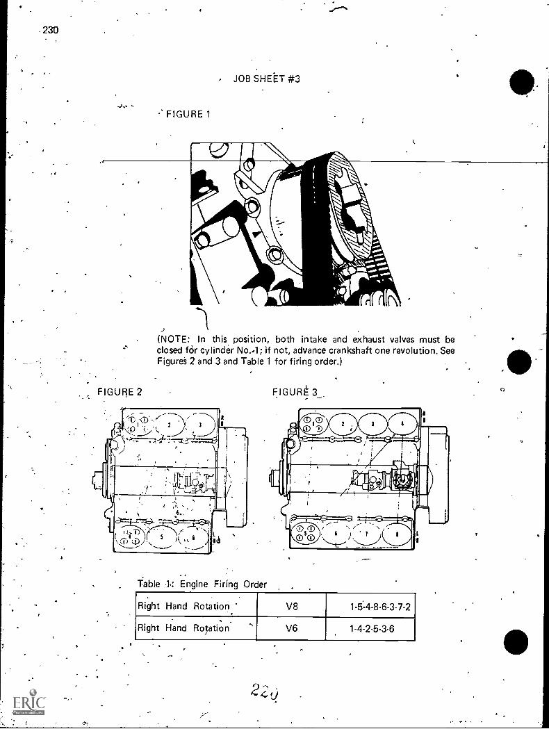
230
4
JOB SHEtT #3
FIGURE 1
(NOTE: In this, position, both intake and exhaust valves must beclosed fOr cylinder No.4; if not, advance crankshaft one revolution. SeeFigures 2 and 3 and Table 1 for firing order.)
FIGURE 2 FIGUR
'fable 1: Engine Firing Order
Right Hand Rotation V8 1-5:4-8-6-3-7-2.
Right Hand Rotation ' V6 1-4-2-5-3-6
2,t)

41
JOB SHEET #3
D:FS-231
2. Adjust injector plunger, then crossheads and valves\of first cylindgr asexplained in the following steps
3. Turn crankshaft in direction of rotation to next "VS" mark correspon-ding to firing order of engine and corresponding cylinder will be readyfor_adjustment (Sep Table 1)
4. Continue turning crankshaft in direction of rotation and Makingadjustments until all injectors and valves have been correctly adjusted
(NOTE: Two complete revolutions of crankshaft are needed to setall injector plungers and valves. Injector and valves can be adjusted foronly one cylinder at any one "VS" setting.)
B. Adjust crosshead
Loosen valve crosshead adjusting screw locknut and back off screwone turn
2. Use light finger pressure at rocker lever contact surface to hold cross-head in contact with valve stem (without adjusting screw)
3. Adjust crosshead adjusting screw according to engine Manufacturer'sspecifications (Figure 4)
FIGURE 4
r
4. Hold adjusting screw in this position and torque locknut to valuesspecified in appropriate service manual (Table 2j
Table 2: Crosshead Locknut Torque
Without ST-669 With ST-669
25 to 28 ft-Iiis(34 to 38 N. m)
22 to 26 ft-lbs- (30 to 35 N. m)

232
JOB SHEET #3
C. Adjust injector plunger
1. Turn adjusting screw down until plunger contacts cup and advancean additional 1° to squeeze oil from cup
2_ Loosea_adjustilig_screw_oneium
3. Using a torque wrench calibrated in in-lbs and a screwdriver adapter,tighten the adjusting screw to values shown in Table 2 for cold settingand tighten:the locknut to manufacturer's specification figures (Figuie5)
FIGURE 5
(NOTE: Some engines use different hot and cold torque settings.)
4. Hold injector adjusting screw and tighten injector adjusting screwlocknut to value specified in appropriate service 'manual (Figure 6)
FIGURE 6
D. Adjust valfes
(NOTE: The same crankshaft position Lised in adjusting injectors is usedfor setting intake and exhaust valves.)
1. Loosen locknut and back off adjusting screw
2. Insert feeler gauge- between rocker lever and top of crossl;ead
(NOTE: Consult appropriate service manuaT for ex-att specifications.)
222

JOB SHEET #3".
D:FS-233
3. Turn screw down until leier just touches gauge and lock adjustingscrew in this position with locknut (Figure 7)
4. Torque locknut to values indicated in service manual
FIGURE 7
223
PT FUEL SYSTEMSUNIT VI
JOB SHEET #4--INSTALL A PT-R FUEL PUMP AND ADJUSTHIGH AND LOW ENGINE IDLE
I. Tools and materials
D:FS-235
A. Basic hand tool set
B. Appropriate service manual
C. Curnmins engine using PT-R fuel pumpl'
D. PT-R fuel pump properly calibrated
E. =Hand tachometer
F. Idle adjusting tool
G. Shop towels
H. Safety glasses
II. Procedure
(CACJTION: Follow all shop safety procedures.)
A. Install pump44,
(NOTE: Injectors and valves should be set to specifications and enginewarmed to operating temperature.)
r,
1. Install fuel pump to accessory drive or to compressor with new gasketand proper rubber buffer, nylon buffer, or spline-coupling and tightensecurely
2. Squirt some clean lube oil into gear pump inlet hole
(NOTE: This aids gear pump fuel pick-up.)
3. Connect the fuel pump Copper line from the pump shut-off valve tothe fuel manifold
(NOTE: The throttle lever linkage should not be connected to thethrottle lever, thus leaving the throttle free for pump adjustments.)
4. Install tachometer to fuel pump tachometer drive shaft connectionor use hand tachometer
5: Connect the shut-off valve electrical connections properly, leaving themanual control button in a closed position (screwed out)
6. Connect pump drain line to housing
22,1"

236'
141
B. Set governor
1. Set idle speed
JOB SHEET #4
a. Operate engine a sufficient period of time to purge air fromthe fuel system and to bring engine up to operating temperature(at least 165° F. oil temperature)
b. Remove pipe plug,from spring pack cover
c. Install idle adjusting tool (Figure 1)-6,
fIGURE 1
d. Operate engine a sufficient period of time to purge all air from thefuel system after idle adjusting tool is installed in spring packCover
e. Turn idle adjusting screw in to increase or out to decrease thereed
(NOTE: The idle adjusting screw is held in position by a springclip. Consult appropriate service manual for exact idle speeds.)
f. Remove idle adjusting tool and replace pipe plug when idle speedis correct
(NOTE: On the mechanical variable gieed governor fuel pumpthe maximum and idle adjusting screws are located on governorcover; adjust idle by loosening rear idle adjusting screw locknut.Screw adjusting screw in or out to get speed required. Tightenadjusting screw )ocknut immediately after adjustment to preventair entrainment.)
..
..
,i
z
JOB SHEET #4
D:FS-237
2. Set rated speed
(NOTE: The engine should be "loaded" on an engine or chassis dyna-mometer to perform this check. Normally, this adjustment is made on
,F1 fup II S - .s-calib-rated and does -notneed to be changed on the engine.)
3. Set engine hi-idle or maximum no-load speed
(NOTE: This check should not be used to check or make governorspeed adjustrnehts. If the hiidle speed is significantly greater thanspecifications, the governor assembly should be examined for malfunc-tion or improper parts.)
l
,
,
s
,
, 22 6
,
!
o
-0
4.,

PT FUEL SYSTEMSUNIT VI
JOB SHEET #5--TEST AND ADJUST A PT-G FUEL PUMP
(NOTE: The job sheet detailed here is aeneral and requires the4dse of test stand manual,pump specification sheet, and the appropriate engine service manual.)
,
I. Tools and materials
A. Basic hand tool set
B. Appropriate service manual
C. Test stand and adapters
D. Test .stand manual
E. Pump special tools
F. PT-G fuel pump
G. Pump specification sheet
H. .Shop towels (lint-free)
I. Safetsses
Procedure4
(CAUf ION: Follow all shDp safety procedures.)
A. Clean purnp exterior thoroughly
B. Drain all fuel from pump and fill with pump stand oil
C. Mount pump as described in pump mounting section of manual
(NOTE: Run all tests with fuel temperature at 90° F.)4.
D.1 Perform the test for pump run-in
1. Determine pump rotation with stand in high range
2. Open pump shutdown valve, manifold valve, and suction valve onpump.
3. Close idle valve and bypass valve on pump discharge line
4.. Turn on pump stand and run uP ta 500 rpm for pump to pick upprime
5. Run pump to rated speed for 5 minutes to seat bearings, flush pump,and purge air . 4
6. , Check for air in flow meter

JOB SHEET #5
E. Perform the test on the gear pump section--Operate tett stand at 500 rpinand close section valve to 25" vacuum
F. Perform the test for pump suction
1. Turn stand to 100 rpm below rated speed
2. Adjust suction valve to 8" vacuum for remainder of tests
G. Perform the test for total fuel flow
1
1. Open manifold valve
2. Close idle and bypass valves
3. Set suction valve to 8" vacuum
4. Raise test stand speed to PT-G pump rated speed given on calibrationsheet .
5. Adjust manifold valve until flow meter float indicates the flow specifiedunder "flowmeter-lb. @cym" pn the calibration sheet
H. PeHorm the test for governor cut-off speed
1. Place throttle in fillrfuel position
2. Increase test 'stand speed tc; a point where pressure begins to dropand check pump speed which should be within limits for "GovernorCut-Off RPM" on calibration sheet
3. Add shims on high speed governor spring if speed, is outside limits
4. Remove shims to lower speed
(NOTE: Each .001" of shim will change 2 rp.m.)
5. After adjusting "Governor Cut-Off AVM" raise stand speed untilpressure gauge drops to 40 psi or what's stated under "GovernorSetting PSI-RPM" in specification sheet
(NOTE: If more than 10-15 rpm higher, a change in governor barreland plunger may be needed.)
I. Perform the test for throttle leakage
1: ()Orate a test stand at rated speed and flow
2. Hold'throttle in idle pOsition with throttle spring
3. Open bypass valve and close manifold valve
4. Place "graduate" under bypass tube -and collect fuel for 30 seconds
22 a

D:FS-241
'JOB SHEET #5
5. Compare doubled amount to specification sheet and adjust frontscrew to required amount
(NOTE: If leakage cannot be reduced, excess wear to throttle shaftis indicated.)
6. Lock screw when setting is correct
J. Perform the test for idle fuel pressure
1. Reduce test stand spBed to 500 rpm or speed stated on specification
2. Open idle valve and close manifold and bypass valve
3. Hold throitle in idle position
4. Note reading on pressure gauge
5. Adjust idle screw in spring back cover to correct pressure
(NOTE: Screw in to increase and o.ut to decreise pressure.)
6. Purge air after each setting
K. Perform the test for manifoldfuel pressure
1. Open manifold valve and close the idle and bypass valve
2. Place throttle in full fuel position
3. Run stand at rated speed and adjust manifold valve to total fuel flow
(NOTE: Pressure should agree to specification; adjust shims in throttleshaft to read 3 to 6 psi higher than specification sheet.)
4. Test flow meter to specifications
5. Turn in rear throttle screw to trim off 3 to.6 psi and bring pumpto specification
6. Recheck governed speed and pressure
L. Check point pressure
1. Reduce stand speed to "Check Point" speed
2. Check manifold pressure at check point speed; if above or below,check torque spring for seating, shimming and part number
3. If spring is changed, recalibrate pump
223

242
stOB SHE T #5
M. Check weight assist pressure
1. Reduce stand speed td 800 rpm
(NOTE: Manifold ressure_shoukLialLmithin_specification under"Weight Assist PSI.")
2. Add shims in governor weight carrier to raiSe pressure.
3. Rernove shims to lower pressure
4. If shireis are changed, recalibrate pump
,
,
'4
..
,
,
N. Drain and remove pump from test stand when calibration is complete
0. Seal all openings in pump
--
*
..
i
.0
,
-,
I

PT FUEL SYSTEMSUNIT VI
JOB SHEET #6--ADJUST AN INJECTOR USING THEDIAL INDICATOR METHOD
I. Tdo1S-and materials
A. Basic hand tool set
D:FS-243
B. Appropriate service manual
C. Typical tool #ST-1170, indicator support
D. Typical tool #ST-1193 rocker lever actuator
E. Clean shop towels
F. Safety glasses
I I. Proced3qc,,
(CAUTIQN: Follow all shop safety procedures.)
A. Pull-Compression release lever back while barring engine
B. Bar engine until "A" or 1-6"VS" mark on pulley is :aligns& with pointer ,1?
on gear case cover
(NOTE: In this position, both valve rocker I9-vers for cylinder #6 must-be free, valves closed, injector plunger for cylinder ft3cmust & at top oftravel; if not, bar the engine 360 degrees andse-align inarks.with, pointer.Y
C. Turn the adjusting screw down on the cylinder_being adjusted until plunger -
contacts cup and advance an additional .16 degreei to squeeze oil from the ,.
cup
Loosen the adjusting screw 1/2 turn
;
1
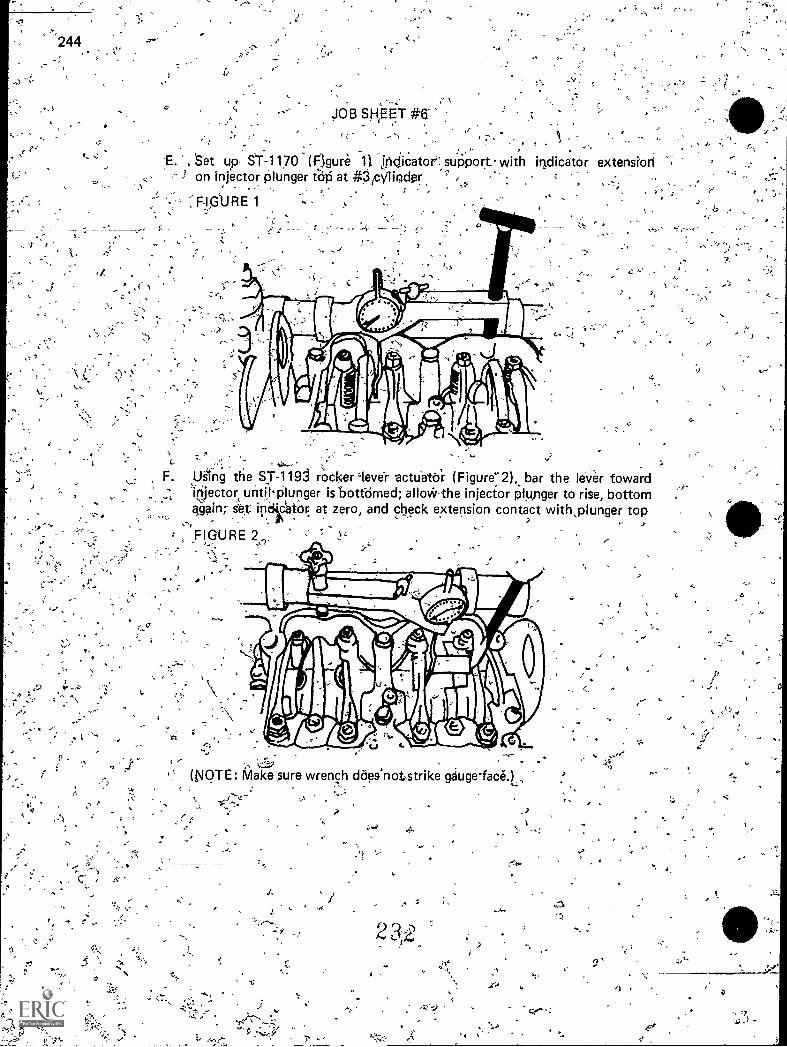
244
JOB SH,EE,T #B
,,
, Set up ST-1170 (Figure 11 'jncticator suPport.. with indicator extensionon -injector Plunger t'OP at #jicVlinder
"7,:k
-;
"'')`1,t5
....IT.
P
F. Using the ST-119J rockerleve? actuator (Figure-2), bar the IeVer toward'injector until'plunger is bottomed; allcrk-the injector plunger to rise, bottomagain; s4 ingickor at zero, and check extension contact with,plunger top-, . .
FIGURE 2<
752
-"Y-((VOTE: Make sure wrench daessnotstrike gauge-face.)
,
""5
.15
;
,.
5, r "
,747
7.7
->
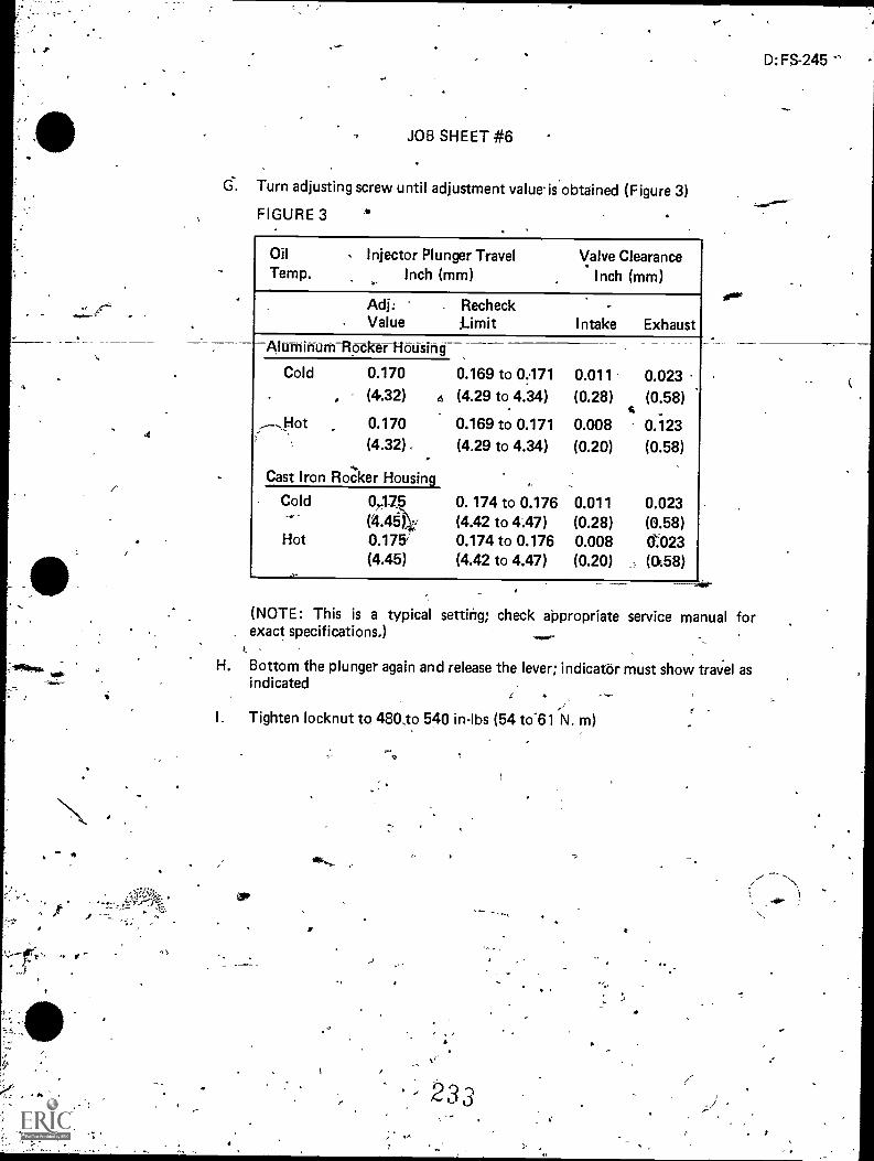
-
.-
JOB SHEET #6
G. Turn adjusting screw until adjustment value.is'obtained (Figure 3)
FIGURE 3
OilTemp.
Injector Plunger TravelInch (mm)
Valve ClearanceInch (mm)
Adj:. Value
RecheckLimit Intake Exhaust
0.023
(0.58)
AlurniffurifRocktr Housing
0.011
(0.28)
Cold 0.170
, (4.32)
0.169 to 0071b (4.29 to 4.34)
Hot 0.170 0.169 to 0171 0.008 0.123(4.32), (4.29 to 4.34) (0.20) (0.58)
Cast Iron Rocker Housing
Cold 0475 0. 174 to 0.176 0.011 0.023(4.461 (4.42 to 4.47) (0.28) (0.58)
Hot 0.175; 0.174 to 0.176 0.008 0023(4.45) (4.42 to 4.47) (0.20) (158)l
D: FS-245
(NOTE: This is a typical setting; check aPpropriate service manual for, exact specifications.)
H. Bottom the plunger again and release the lever; indicator must show travel asindicated
I. Tighten locknut to 480,to 540 in-lbs (54 to'61 N. m)
- 23 3

PT F.UEL SYSTEMSUNIT VI
NAME
TEST
D:FS-247
1. Match terms on the right with their correct definitions.
a. Pressure time system based on the princAplethat the volume of liquid flow is proporffon-ate to the fluid pressure, the time allowed toflow, and the size_of the_passagethroughwhich the liquid flows
b. PT fuel pump which is governor controlled
PT fuel pump,
which is _pressure regulated
d. To get rid of trapped fuel
Engine rpm's under full load
To supply in a measured amount
Engine rpm's with no-load and throttlefully open
h. Air fuel ratio control
2. Name the three main parts of d PT fuel system.
a.
b.
C.
1. Purge
2. Meter
3. PT type G
4. PT type R
5. High idle ormaximum no-load speed
6. PT syitem
7. Rated speed
8. AFt
3. Match the main units of a PT pump assembly, on the right with their functions.
a. Draws -fuel from supply tanI5 forcing itthrough the pump filter screen into thepressure regulator valve
b. Limits the pressure of the fuel to the injectorsAlit,
c. Provides a manual control of fuel flow to theinjector under all conditions in the opferating.range
d. Controls the flow of fuel from idle to maid-inuM,governor speed
234
1. Pressureregulator
2. Gear punip
3. Governor,assembly
4. Throttle

248
4. Select true statements concerning the operation of a PT injection system by placing an"X" in the appropriatetlanks.
a. Gear type fuel pump delivers fuel through a rettricting throttle to thegovernor
b. From the fuel pump, the fuel goes to a manifojd which feeds cam-operatedinjectors in the cylinder head
c. Injector raises pressure to produce a good spray an& times the start ofinjection
State the function of a pulsation damper..
6. Complete the following list of statements concerning the operation of a mechanicalgovernor.
a. Between idle and maximum speed, fuel flows through the governor to the injectorin accordance with engine requirements as controlled by the throttle
b. When engine reaches governed speed, the governor weights move the governorplungers so fuel passage to the injectqrs is
c. Fuel leaving the governor floWs through the shut down vtive, inlet supply lines,and onto the
7. Name two types of PT injectots.
a.
b.
8. Match the operational steps of PT injectors at the right wjth their descriptions;
a. 1) Fuel enters the, injector t fuel inlet 1. Injection
2) Metering orifice controls quantity of fuel 2. Meteringthat enters the injector cup
.3. Purgi'n,gb. 1) Downward, plunger movement cuts off
fuel entry.into injector cup
2) Continued doWnward movement forcesfuet from injector cup through theorifice into cOmbustion chamber
3) While plunger is down, fuel -passesthrough upper hole around undercut'in plunger through return passages
to the fuel tank
a
235
4. Air fuelratio control
D:FS-249
c. 1) Plunger remains se.;ted after injection
.2) Plunger rises on next metering operation
d. 1) Made to replace the PT-G .pump acidanerdid on turbocharg4d engines
2) Limits fuel pressure and flow restriction
3) Gives the correct air fuel delivery rate tothe engine during acceleration
9. Demonstrate the ability to
a. Remove and install flange type PT injectors.
b. Remove and install PT (type B, C, and D) injectors.
c. Adjust an injector plunger and valves using the torque method.
d. Install a PT-R fuel pump and adjust high andlow engine idle.
e? Test and adjust a PT-G fuel pump.
f. Adjust an injector using the dial indicator method.
'(NOTE: If these activitiei have not been accomplished prior to the test, ask yourinstructor when they should be completed.)

PT FUEL SYSTEMSUNIT VI
ANSWERS TO TEST
1. a. 6b. 3C. 4d. 1
e. 7. f.
9. 5h., 8
2. a. Fuel pumpb. Supply lines, drain lines, and passagesc. Injectors
3. a. 2b. 1
C. 4d. 3
6
D: FS-251
4. a, c
5. The damper ntaini a eel diaphragm which absorbs pulsations and smooths fuelflow through system
6. b. Shut offC. Injectors
7. a. F langedb.. Cylindrical
8. a. 2b. 1
c. 3d. 4
9. Performance skills evaluated to the satisfaction of the instructor
.)
,.
_
,
INJECTION NOZZLESUNIT VII ..
UNIT OBJECTIVE
D:FS-253
,After completion of this unit, the student should be able to list the functions of an injection
nozzle and match types of nozzles with their characteristics. The student should also be ableto demoristrate the ability to remove, service and test ari injection nozzle. This knowledgewill be evidenced by correctly- perf6rming the procedures outlined in the job sheets andbyscoring 85 percent on the unit test.
SPECIFIC OBJECTIVES
After completion of this unit, the student should be able to:/
1. Match 'terms related to injection nozzles with their correct definitions.
2. List two functions of an injection nozzle.. '
AISPortba3. Name four moving parts in an injection nozzle. Y.
4. Name three common types of nozzle valves...
5. Match the types of nozzles with their characteristics.---\
6. Select true statements concerning the operation of an injection nozzle.
7. Explain how the nozzle opening pressure is adjustedt
8. Demonstrate the ability to:,
a. Remove, service, and test an injection nozzle.
b. Install an injection nozzle.
c. Isolate a faulty injection nozzle...
,b23 0
-.0

INJECtION NOZZLESUNIT VII
SUGGESTED ACTIVITIES
I: Provide student with 'objectit/e sheet.
Provide student with information and job sheets:
III. Make transparencies.
IV. Discuss unit and specific objectives.
V. Discuss information sheet.
VI.. Demonstrate and discuss the procedures outlined in the job sheets.
VII. Demonstrate lapping and cleaning procedures.-
VIII. Show students different ways an injector may be held in place.
IX. Demonstrate how to clean injector area prior to injector removal.
X. Discuss the use of capsule-type fuel nozzles on Caterpillar engines.
. XI. Give test.
INSTRUCTIONAL MATERIALS
Included in tills unit:
idt. Objective sheet
B. Information sheet
C. Transparency masters
1. TM 1--Moving Parts in Nozzle
2. TM.2--NoZzle Valve Assembly
D. Job Sheets
1, Job Sheet #1--Remove, Service, and Test an Injection Nozzle'
2. Job Sheet #2-.-Install an Injection Nozzle
3. Job Sheet #3--Isolate a Faulty Injection Nozzle
° E. Test
F. Answers to test
239
D:FS-255
256
II. References:
A. Toboldt, William k, Diesel Fundamentals, Service, Repaii. South Holland,I L: .Goodheart-Willcox Company, Inc.; 1980.
B. Kates, Edgar J., and 1..uckMilliam E. Third.'Ecntion, Diesp! aPd High Com-pression Gas Engines. Chicago: American Technical Society, 1974.
C. Fundamentals of Service: Engines. Fifth Edition. Moline, IL: Deere andCompany, 1980.
D. Robert Bosch Corporation Bulletin, No. 221103. 4131 A Directors Row,Houston, TX 77018.
E. Dagel, John F. Diesel Engine Repair. New York: John Wiley and Sons, teA
Inc., 1982.
F. Foutes, William A. Diesel Engine Mechanics. Stillwater, OK: Mid-AmericaVocational:Curriculum Consortium, 1977.

a
a
D:FS-257
INJECTION NOZZLESUNIT VII
INFORMATION SHEET
I. Terms and definitions
A. Pintle-Valve in which tile end extends into a shank or pin
B. Orifice-Small hole
C. Injection nozzle-Nozzle, nozzle holder, valve, and spring assembly
D. Noae assembly--Valve, body, and spray valve
IC' Functions of injection nozzle
A. Atomizes the fuel for better combustion
B. Spreads the fuel spray to fully rhix with air
III. Moving parts (Transparency 1)
A. Valve
B. Spring#
C. Spindle
D. Retainer
IV. Common types of nozzle valves (Transparency 2)
A. Single hole
B. Multiple orifice
Pintle type, sirde hole
'V. Nozzle characteristics (Traniparency 2)
A. Hole type-Used for engines with open combustion chambers
B. Pintle type (inward-opening)-Produces a hollow spray; used-for engines withprecombustion chambers or energy cells-
C. Pintle type (outward-openirig)--Does not dribble fuel; used for engines withprecombustion chamber or energy cell
D. Multiple orifice--Variation of pintle type; holet have a tendency to clog
1

. 258
..
i
INFORMATION SHEET,
.,
VI. Operation of jnjection nozzle
A. 'Hydraulically operated by Nei delivered from the injection pump
B. Spring loaded valve is lifted allowing pressurized fuel to spray out throughone or more orifices into combustion chamber
(NOTE: Some injection nozzles have adjustable valve lifts. Refer to manu-facturer's service manual.)
*
VI I. Adjustment of nozzle opening pressureAdjusted by a screw or shims on thevalve spring (Transparency 1)
..
-1
i
,

Fuel Leak-Off
Pressure Adjusting
Screw..
Pressure Sprinh
Locating Clamp
Nozzle Body
Seal
Moving Parts In Nozzle
(Lift Adjusting Screw
243 -
Fuel Inlet
Nozzle Valve
ray Tip
Retaining Screwasket
Protection Cap
Retaining Screw
Spring Adjusting
Retaining Cap Nut
Spindle Assembly
Nozzle Cap Nut
Protection Cap
Gasket
Pressure
Adjusting Spring
Nozzle Holder
Body
Dowel PinNozzle Gasket
ADB Nozzle Assembly
244K.)01co

g0111111.
:
Nozzle Va ve Assembly.
Valve
Fuel Duct
4.1
iI
.1
Closed Qpen
OutwirdTOpe ni ng,
ifitle-Type.Pressure Cnamber
, Pi ntle Orifice
9
Closed Open ; a.I cnK j n w a r d- 0 pe n i n g r;)
243 Hole-Type 2 '1
_.
6
;

J.
D:FS-263
INJECTION NOZZLES.UNIT VII
a.
JOB SHEET #1REMOVE, SERVICE, AND TEST Al%1. INJECTION NOZZLE
ciere
Tools and materials
A. Nozzle tester
B. Appropriate service tool kit
C. Appro icpriate serve manual
D. Saiety glisses
Il Kocedure
(NOTE: The job sheet detailed here is .6eneral; for specific installations andmodels, follow the specifications and procedures according to the engine manu-facturer's instruction manual.)
(CAUTION: FPIlow all shop safety proceduids.)
A. RemoVe 'nozzle
1. Clean the' area around the nozzle
Reni9seirrefpi .the injection and leak-off lines
B.
.3. Remove the nozzle from the engine,
(NOTE: Some nozzles may re'quire pial tools or procedures forremoval. See manufacturer's-seivice manual.) >
,
Clean nozzle.
1. Soak *tire nozzle asiembly in c.lean solvent orcalibration fluid afterdiscarding outer seals
4
(
s. 7'
40.

264
fa
JOB-SHEET #1
2. Clean and decarbon spray tip and nozzle body with a brass wire brush(Figure 1)
(NOTE: Never use emery cloth or steel wiretrush because the precisiontip will be damaged.)
FIGURE 1
C. Test nozzle
(NOTE: All nozzles require careful handling a'nd a special tool kit to performany service. When working on several nozzles, DO NOT mix nozzle parts.)
1. Place nozzle into nozzle holder
2. ;lighten nozzle nut, first by hand, then with correct size wrench
3. Torque nozzle according to the values given by the engine manufac-.turer's specification
4. Connect the nozzle holder with the delivery line to the tester
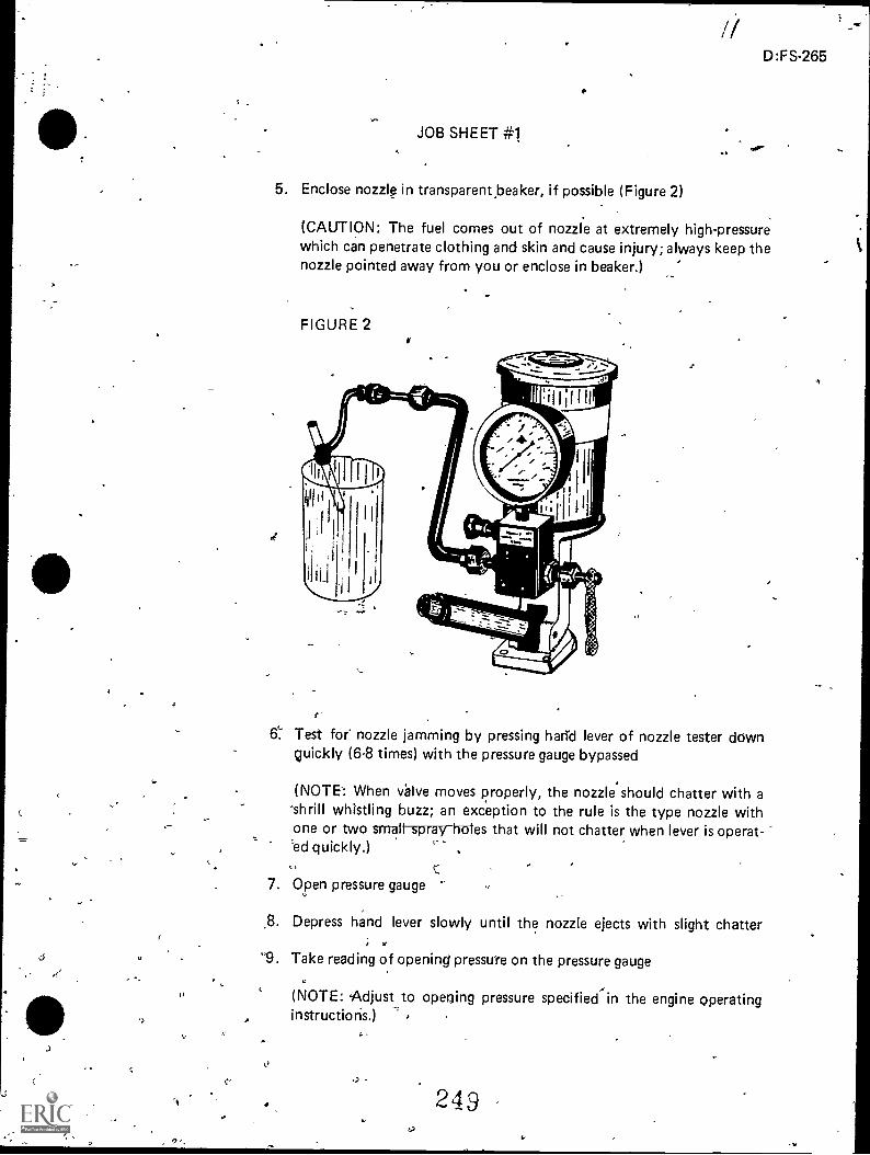
I)
/1
JOB SHEET #1
5. Enclose nozzle in transparent beaker, if possible (Figure 2)
D:FS-265
(CAUTION: The fuel comes out of nozzle at extremely high-pressurewhich can penetrate clothing and skin and cause injury; always keep thenozzle pointed away from you or enclose in beaker.)
FIGURE 2
6`. Test for nozzle jamming by pressing hand lever of nozzle tester downquickly (6-8 times) with the pressure gauge bypassed
(NOTE: When Valve moves properly, the nozzle should chatter with a
-shrill whistling buzz; an exception to the rule is the type nozzle withone or two small spray holes that will not chatter when lever is operat-, -"ed quickly.)
7. Open pressure gauge
.8. Depress hand lever slowly until the nozzle ejects with slight chatter;
9. Take reading of opening pressuYe on the pressure gauge
(NOTE: .Adjust to opening pressure specifiedin the engine operatinginstructions.)
0
,)
2 4 9
b

266
-le
.. .0JOB SHEET
_
10. Turn adjusting screw, (Figure 3), or change total shim thickness (Figure4), if reading differs from gpecified opening pressure
(NOTE: Ofiening pressure is not adjusted by shims on all models.)
FIGURE 3 FIGUR-EA
D. Test leakage-Operate the hand lever of the nozzle tester until the pointer onthe pressure gauge indicates 285 psi below the specified 'opening pressure
(NOTE: The nozzle is considered leakproof if no oil emerges at the nippletip within 10 seconds.)
2
4111
Ir)
4
.D:FS-267
INJECTION NOZZLESUNIT VI I
,JQB SHEET #2-INSTALL AN INJECTION NOZZlA
I. Tools and materials
A. Basic shop.tools
B. -Appropriate service manual
C. Cleaning solvent
D. Torque wrerich
E. ; Typical thols as requ'ired
Piocedure
(CAUTCON: Follow all shop safety procedures.)
A. Clean nozzle in diesel fuel
B. Clean area around nozzle (seat or bore)
C. Clean nozzle tube of any foreign material
D. Install new seal washer
E. Place nozzle carefully in cylinder head
F. .Tighten nozzle hold-down bolts evenly
G. Torque nozzle bolts or nuts to manufacturer's specifications
H. Connect fuel lines to injector
I. Torque fuel lines to Manufacturer's specifications
(CAUTION: Do not overtighten fuel line(s] as this will damage fuel line.)

,
INJECTION NOZZLESUNIT VII
JOB SHEET #3--ISO LATE A FAULTY INJECTION NOZZLE
I. Tools and materials
A. Basic hand tools
B. Appropriate service manual
C. Remote tachometer
D. Clean diesel fuel
E. Clean shop towels
F. Safety glasses
I I. Procedure ..
. (CAUTION: Follow all shop safety pr:Ocedures.)
A. Disconnect tach drive cable..
B. Connect remote tachometer
C. Start the engine
D. Loosen injector line on #1 cylinder
(NOTE: Fuel flow should be evident.)
E. Listen fqr a change in engine speed, and watch
r
D:FS-269
tachometer for an rpm drop
(NOTE: An injector that is operating correctlyengine; refer to manufacturer's specifications
F. Repeat for each cylinder
G. Remove and repair any fauity nozzles
252
will cause an rpm drop infor the 'correct amount.)
,
I
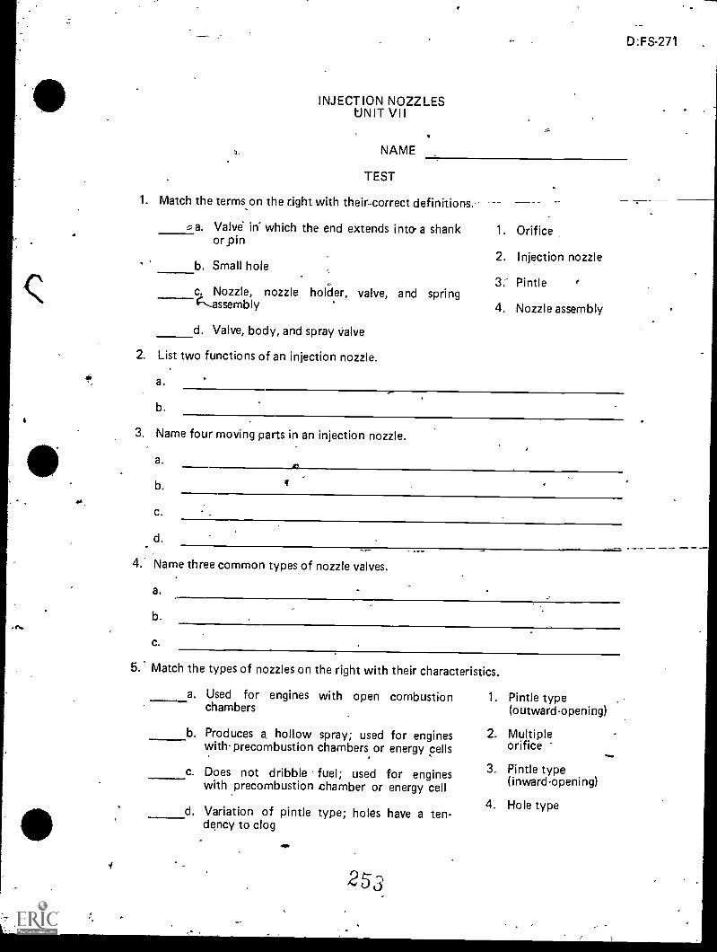
INJECTION NOZZLESUNIT VII
NAME
TEST
1. Match the terms on the right with their-correct definitions.
=-,a. Valve irf which the end extends into a shankorpin
b. Small hole
c. Nozzle, nozzle holder,C----assembly
valve, and spring
d. Valve, body, and spray valve
2. List two functions of an injection nozzle.
a.
b.
D:FS-271 ,
,-.
_
1. Orifice
2. Injection nozzle
3: Pintle r
4. Nozzle assembly
3. Name four moving parts in an injection nozzle.
a.
b.
C.
d.
MI
I
4. Name three common types of nozzle valves.
a.
b.
c.
5. Match the types of nozzles on the right with their characteristics.
a. Used for engines
I
chambers
b. Produces a, hollowwith- precombustion
c. Does not dribblewith precombustion
d. Variation of pintledency to clog
with open combustion
spray; used for engineschambers or energy cells
fuel; used for engineschamber or energy cell
type; holes have a ten-
253
1. Pintle type(outward-opening)
2. Multipleorifice
3. Pintle type(inward-opening)
4. Hole type
,
4.

272. -
6. Select true statements concerning the operation of an injection nozzle by placing an"X" in the appropriate blanks.
p
c...
a. H.ydraulically operated by fuel delivered from the injection pump
b. Spring loaded valve is lifted allowing pressurized fuel to sprayout through one or more orifices into combustion chamber
7. Explain how the nozzle opening pressure is adjusted.
8. Demonstrate the ability to:
a. Remove, service, and test an injection nozzle. ,
b. Install an injection nozzle.
c. Isolate a faulty injection nozzle.
(NOTE: If these activities have not been accomplished prior to the test, ask yourinstructor when they should be completed.)
,
,
_
e
,.

-1/
*
\
.
.
INJECTION NOZZLESUNIT VII
ANSWERS TO TE6T
a. 3b. 1
C. 2d. 4
2. a. Atomizes the fuel for better combustionb. Spreads the fuel spray to fully mix with air
3. a. Valveb. Springc. Spindled. Retainer
4. a. Single holeb. Multiple orifice .c. Pintle type, single hole
.,
(3.:F-273
--]
5. a. 4 .b. 3c. , 1
d. 2..
6. .a, b
7, Adjusted by a screw-or shims on the valvespring
8. Performance skills evaluated to the satisfaction of the instructor
-
,
..
25-5
.
.
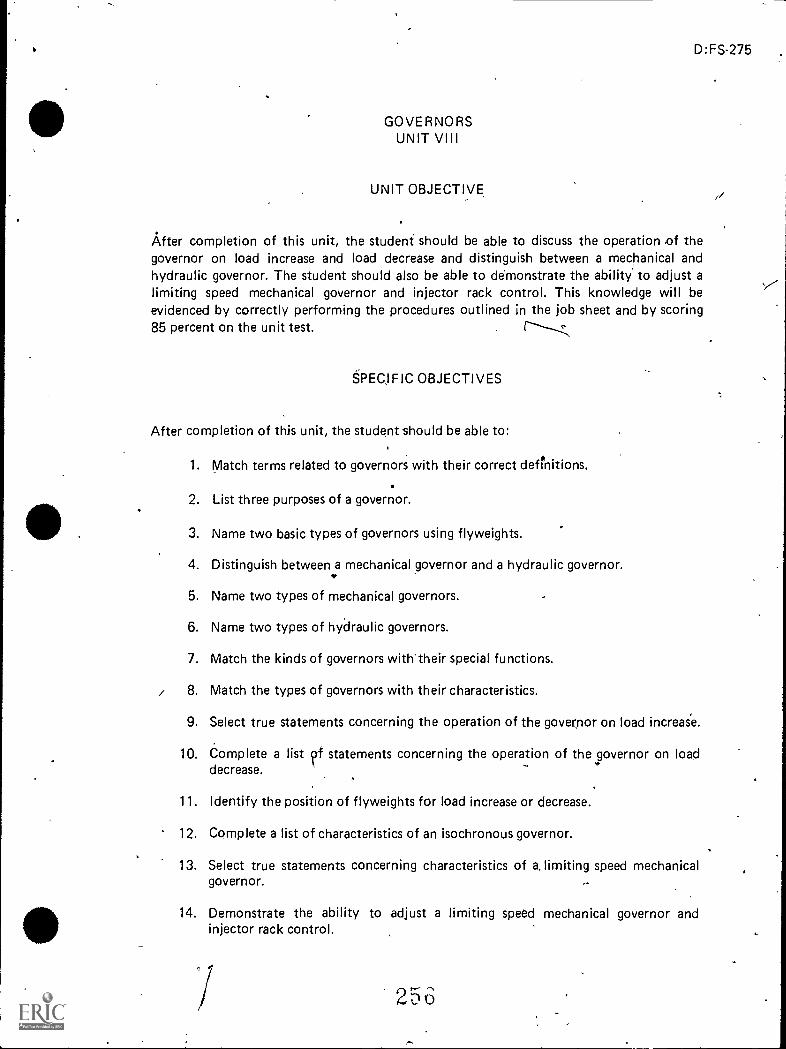
_
D:FS-275
GOVERNORSUNIT VIII
UNIT OBJECTIVE
After completion of this unit, the student should be able to discuss the operation of thegovernor on load increase and load decrease and distinguish between a mechanical andhydraulic governor. The student should also be able to ddmonstrate the ability' to adjust alimiting speed mechanical governor and injector rack control. This knowledge will beevidenced by correctly performing the procedures outlined in the job sheet and by scoring85 percent on the unit test.
SPECJFIC OBJECTIVES
After completion of this unit, the student should be able to:
1. Match terms related to governors with their correct definitions.
2. List three purposes of a governor.
3. Name two basic types of governors using flyweights.
/I
4. Distinguish between a mechanical governor and a hydraulic governor.*
5. Name two types of mechanical governors.
6. Name two types of hydraulic governors.
7. Match the kinds of governors with-their special functions.
/ 8. Match the types of governors with their characteristics.
9. Select true statements concerning the operation of the governor on load increase.
10. Complete a list irf statements concerning the operation of the governor on load..
decrease.. .
11. Identify the position of flyweights for load increase or decrease.
12. Complete a list of characteristics of an isochronous governor.
13. Select true statements concerning characteristics of a, limiting speed mechanicalgovernor.
14. Demonstrate the ability to adjust a limiting speed mechanical governor andinjector rack control. ,
2 5 6
,/'
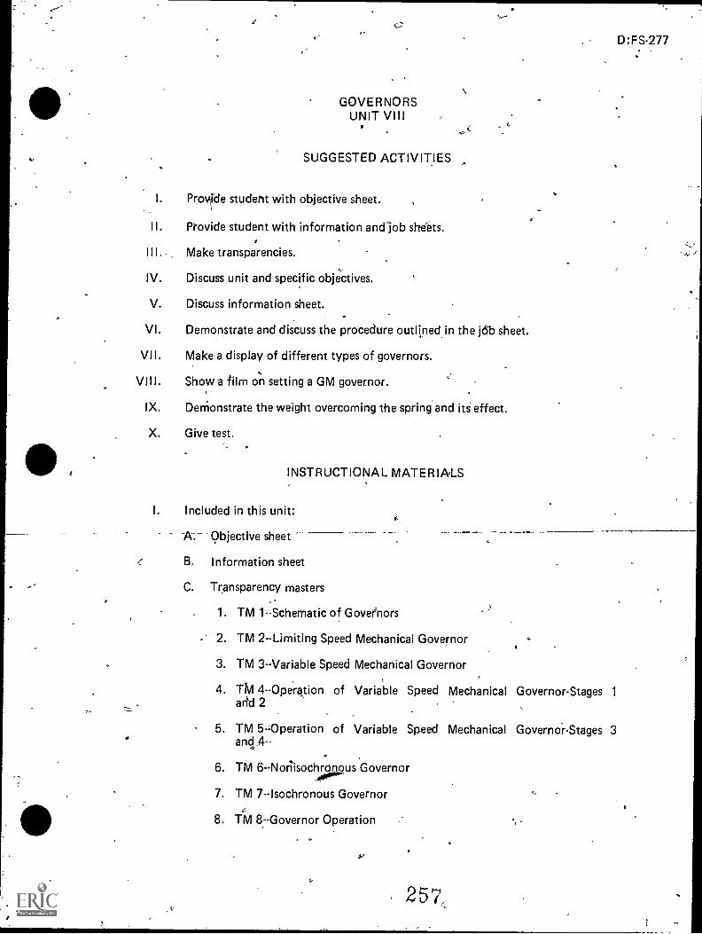
z
GOVERNORSUNIT VIII
SUGGESTED ACTIVITIES
I. ProvIde student with objective sheet.
II. Provide student with information andlob shebts.
Make transparencies.
IV. Discuss unit and specific objectives.
V. Discuss information sheet.
VI. Demonstrate and discuss the procedure outlined.in the jc5b sheet.
VII. Make a display of different types of governors.
VIII. Show a film on setting a GM governor.
IX. Denionstrate the weight overcoming the spring and iti effect.
X. Give test.
INSTRUCTIONAL MATER IA,LS
I. Included in this unit:
A. Objective sheet
B. Information sheet
C. Transparency masters
1. TM 1--Schematic of Govenors
- 2. TM 2--Limiting Speed Mechanical Governor
3. TM 3--Variable Speed Mechanical Governor
4. TM 4--Operation of Variable Speed Mechanical Governor-Stages 1
arid 2
D:FS-277
5. TM 5-Operation of Variable Speed Mechanical Governor-Stages 3anci 4--
6. TM 6-Norlisochronous Governor
7. TM 7--Isochronous Governor
8. TM 8--Governor Operation
257_

278
0
D. Job Sheet #1--Adjust a Limiting Speed Mechanical Governor and InjectorRack Control
E. Test
F. Answers to test
References:
A. Kates, Edgar J., and Luck, William E. Diesel and High Compression GasEngines. Third Edition. Chicago: American Technical Society, 1974.
B. Fundamentals of Service: Engines. Fifth Edition. Moline, IL: Deere andCompany, 1980.
C. Toboldt, William K..Diesel Fundamentals, Service, Repair. South Holland,IL: Goodheart-Willcox Company, Inc., 1980.
D. Dagel, John F. Diesel Engine Repair. New York: John Wiley and Sons,Inc., 1982.
E. Foutes, Williarn A. Diesel Engine Mechanics. Stil lwater,'OK: Mid-AmericaVocational Curriculum Consortium, 1977.
alto
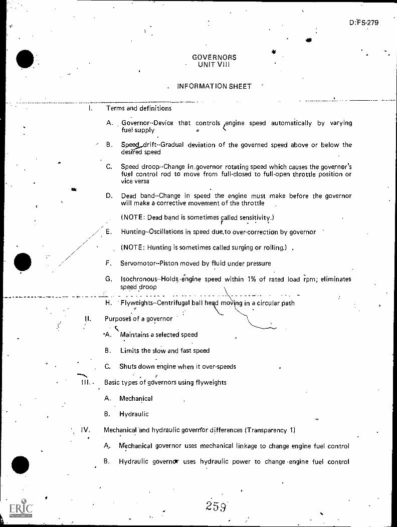
GOVERNORSUNIT VIII
INFORMATION SHEET
I. Terms and definitions
D:'FS-279
A. Governor--Device that controlsen
gine speed automaiically by varyingfuel supply
B. Speed..drift--Gradual deviation of the governed speed above or below thedes?led speed
C. Speed droop--Change in,governor rotating speed which causes the governor'sfuel control rod to move from fullclosed to full-open throttle position orvice versa
D. Dead band--Change in speed the engine must make before the governorwill make a corrective movement of the throttle
(NOTE: Dead band is sometimes called sensitivity.). .
Hunting--Oscillations in speed due,to over-correction by governor
(NOTE: Hunting is sometimes called surging or rolling.) .
F. Servomotor--Piston moved by fluid under pressure
G. Isochronous--Holds ,engine speed within 1% of rated load rpm; eliminatesspeed droop
H. Flyweights--Centrifugal ball he cr.irloy'ng in a circular path
(I. Purposes of a governor
A. Maintains a selected speed
B. Limits the sloW and fast speed
, C. Shuts down engine when it over-speeds
,III.. Basic types of gdvernors using flyweights
A. Mechanical
B. Hydraulic
IV. Mechanical 'and hydraulic goverrfor differences (Transparency 1)
A, Mechanical governor uses mechanical linkage to change engine fuel control
B. Hydraulic governor uses hydraulic power to change engine fuel control
259

280
lNFORMATION SHEET
V. Types of mechanical governors (Transparencies 2, 3, 4, and .5)
A. -Limiting speed
B. Variable speed
VI. Types of hydraulic governors (Transparencies 6 and 7)
A. Permanent spe droop
(NOTE: Speed d op is applied to prevent hunting.)
B. Temporary speed droop
(NOTE: Speed droop is applied and then withdrawn so governor becomesisochronous.)
VII. Governors and their special functions
A. Variable speedMaintain& any selected engine speed
1,
B. Over-speed--A safety device which shuts down the engine in case it runs toofast
C: *Loadlimitin2--L'imit§ the !pad to prevent overloading the engine at.whateverspeed it may be running
. )D. ,Load control--Adjusts the amount of load applied to engine to suit the speed
at which -it is set to run
VIII. Characteristics of mechanical and hydraulic governors
A: Mechanical
a1. Has large eaci bands
_j2. Power is small c
3. Unavoidable speed droop
B. Hydraulic
1. Is not isochronous
2. Speed droop is not convenient to adjust
(NOTE: Speed droop must be applied and then withdrawn to becomean isochronous hydraulic governor.)
(>

^4,
3r-
7
,, c
"3>
--.!).- r3:- n
rz:
C
"
4
,
c' 37 '
twoRro'd-fioNSHEET
cs Operation of.governor on load-increase (Transparency d)
(NOTE: Engine speed decreases as load increases.),.: ,.....,..,
A. iY-Inieights.rotate sG;ver ,,
.B.-.. Speeder spring 'forces overtorne centrifugal force of flyweigllAs
Speeder rod moyesidown6 open fuel valve to increase fuel
J
,1-Operation df governorron load,decrease (Transparency 2-)
, ..,. ., ,-
.(N.0`TE: Ecigine sp'eed increases avlqad decreases.),, ,._
, . N,...,,,z.- ,
,..)0k. Flyiyeidhts rotate faster .. ,..
. ,:, ,.- ;, ,....,. - ,,,
B. Spea-der spring force'is overcoMe by cenrifugal force of fiyyveighs _. . . .. ,.
Speeder roil rnoveS:up'forcfn fciel va'ivato, close:._ ...:. .. - ;.,,,-
...
Posit(on ctf flyvVeightsVransparency 8)., -
. . ...: ..,,_,
LoacilincreSse-F-lyweights move.inI ,
; B. Load clecrease-fly4ighfs move but (
,
...... .:.,, . ._
Charctaeristics of an isochroribus goVernor.- --,.
,
)
'23
rD:FS,281
a
)
Ac-
:ylaintains constant speedwithoutfpnimg
4
;
B. Speed droo-P is temporary.,(NOTE: SpeeddrOop is employed to,give sfabillty 41ile fUel is being Corrected,ancrapeeddrodci is remOved-as engine responds to fue( charage.)
C,
gnaractellsticinf a limitit6 sPeed mechanical gdyernipc (rrapiparency 2)
A. 'Controls engine idle speed., '
B. Limi maximuni operating Speed- _
C. Can:have singte or.dc4ble
-
'
rot..
.e>
,--))
,
1;1
II-
',
(J.
ers3,
,
e >)
.
- . : ;-*/
f::

;
)
p..44
Schematic of G-overnors
Ldad DecreaSe on-MeChinieal Governor
,
)
Oil Supply
Fuel Control,Valve
FueI
4
pilotValve
. -
Fuel to,Engine
(Redued)
0.
Hydraulic Governor
mreased Fuel 4. 0Loh i T h rot ti e
,
.1K
'\Drain
/
Power Piston
263'0:11C/)fJCOCA)

D: FS-285
.-
Limiting Speed Mechanical Governor
SpeedContrOlLever
ReturnSpringSpring
RetainerWashe
DifferentialLever
Spacer
WeightAssembly
StopLever
OperatingShaftLever
GapAdjusting
Screw
Upper_Bearing
Operating -
. ShaftWerght Shaft.Bearing
BearingRetaining Bolt
Housing PlugWeight
Shaft
4S41/40i..N. gial
11111117411 IVgliallII ',14rilow.
.............*4 F.rki4 T
Riser RiserThrust
.Bearing
CrossSection of Single Weight Limiting Speed Mechanical Governor
TM 2
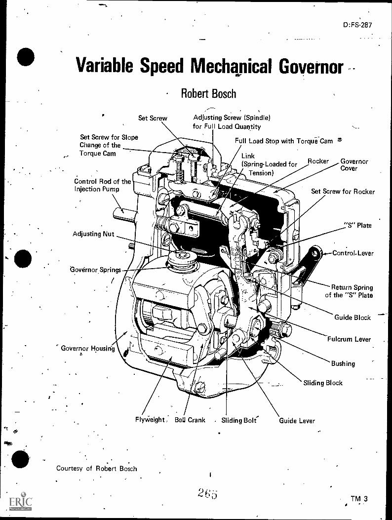
-
...
D:FS-287
-
Variable Speed Mechanical Governor
so
A
e-,
Set Screw
Set Screw for SlopeChange of theTorque Cam
Control Rod of theInjection Pump Set Screw for Rocker
Robert Bosch,----.
A
Adjusting Screw (Spindle)for Full Load Quantity
Full Load Stop with Torque-Cam
Link(Spring-Loaded for
Tension)
s,
Rocker GovernorCover
Adjusting Nut
*Govdrnor.Springs
/
Control. Lever
Return Springof the "S" Plate
Governor HousirigA
..,
Flyikeight, BeU Crank Sliding Bolt'
Courtesy of Robert Bosch, I
2 6 b-
Guide Block
Fulcrum Lever
Bushing
Sliding Block
Guide LeverA
TM 3

44
1
(
Operation of Variable Speed Mechanical Governor
Stages land '2,
,
1. 'Start .Position.
1
K Courtesy of Robert Bosch.I.
266
I
,
2. Full-Load Quantity at Low Revolutional Speed.Start of the Torque Control.

Operation of Variable Speed Mechanical Governor
Stages 3 and 4
3. Full-Load Quantity at Moderate Speed.
, Reversal -of Torque Control.. . _ ,,
--Ig Courtesy of Robert Bosch01 '
26a
4. Maximum Full Load Rotation Speed.End of Torque Control(Dashed Lines=Break-Away).

Nonisochronous Governor
Speed-Droop Lever
Speed Droop
Fuel Control Shaft Pin,
Ball-Arm.
Supply of OilUnder
Pressure rPilot-ValvePlunger
Fuel to Engine Reduced)
Effect of Load Decrease on HydraulicGovernor With Speed-Droop Lever
Speeder
Spring
Fuel
Control'Lever
Power Piston
PowerPiston
TrappedFuel OilControlValve
Fuel
27u
Floating LeverA.
Speeder Spring
Speed Adjusting
Shaft (Fixed)
4eall-Arm Flyweight111 Pilot-Valve .Plu er
Pressure Oil
Pilot ValveBushing
Regulating PortSupply Gear Pump
To Engine Sump
t.,2 (1
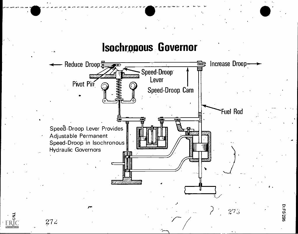
illM ,... ,..... .,.. ,,,, ... 36., ... ,- ,,. r r 3+, ...0. .a.. ..", w... i-r., -no -ay. -it
Isochropous Governor
-4-- Reduce Droop
. 4E-:-
Speed-Droop..... Lever
I.O.PAnr
Pivot Pin' ____, 0_,....
-:--,- Speed-Droop Cam. ....:_ I_;..
increase Droop--0-,
Spedl-Droop Lever ProvidesAdjustable 'Permanent .
Speed-Droop in IsochronousHydraulic Governors
if*
27
rki

)
'
f` Governor Operation
Load Increases,
ErAine Speed Decreases
-Flyweights Rotate
Slower,
- )b
Fuel Flow Increased
Increased Load
Load Decreases,,. -
Engine Speed Increases6
Flyweights Rotate
Faster
C
ruel FlOw Decreas6d
Decreased Load
Operation of Centrifugai"Governor
4

D:FS-299
GOVERNORSUNIT VIII
JOB SHEET #1--ADJUST A LIMIT[NG SPEED MECHANICALGOVERNOR AND INJECTOR RACK CONTROL
I. Tools and materials
A. Basic hand tool set
B. Appropriate service manual
C. :Clean shop towels
,II. Procedure .
4. (CAUTION: Follow all shop safetypro'cedures.)
A. Adjust limiting speed mechanical governor and injector rack control
(NOTE: These procedures should be completed after adjusting the exhaustvalves and timing the fuel injectors.)
1. Adjust governor gap--Single weight governor
a. Start engine and bring to operating temperature
b. Stop engine
c. Loosen the lever and disconnedt the fuel modulator, the powercontrol device, the load limiting device, or the air cylinder link, if-
<the engine is so equipped
d. Remove the two attaching bolts
e. Withdraw the governor high speed spring retainer cover-
2
t.

300
JOB SHEET #1
f. Back out the buffer screw until it extends approximately 5/8k
Buffer Screw
from the locknut (Figure 1)
FIGURE 1
g. Start the engine
h. Loosen the idle speed adjusting screw locknut
i. Adjust the idle.screw tor-obtain the desired idle weed
Fuel Rod
the screw and tighten *the locknut to retain the adjustment
(NOTE: The recommended idle speed is 556 rpm for singleweight governors but may vary with special engine applications.)
4k. Stop the engine
I. Remoife the governor cover and lever assembly
m. Clean and remove the valve rocker cover
4
,
0
I
,n. Remove the fuel rod from the differential lever and the injector
control tube lever
2 71'1

,
,t4
6
JOB SHEET #11
D:FS-301
o. Check the gap between the low speed spriA cap and the highspeed spring plunger with gauge (Figure 2)
Spring Cap
-FIGURE 2
..
Gauge
,.
Adjusting Screw
Lock hut
i
Spring PlungerI
..----p. Loosen the locknut and turn the gap adjusting screw until a slight
drag is felt on the gauge, if required
q. Hold the adjusting screw
r. Tighten the locknut
s. Recheck the gap and readjust if necessary,
t. Install the fuel rod between the governor and injector control tubelever
u. Install the governor cover and lever assembly
2. Adjust governor gap on a double weight governor
a. Start engine
b. Bring t6 operating temperature
c. Stop engine
d. Remove the two attaching bolts
e. Withdraw the governor high speed spring retainer cover
f. Back out the buffer screw until it extends approximately 5/8"from the locknut (Figure 1)
g. Start the engine
I
- ..

302
JOB SHEET #1
h. Loosen the idle speed adjusiing screw locKnut (Figure 3)
FIGURE 3
Idle Scre
Idle Speed Locknut
-i. Adjust the screw to obtain the desired idle speed
j. Hold the screw and tighten the locknut to retain the adjustment
(NOTE: The recommended idle speed is 450 rpm for doubleweight goveinors, but may vary with speciarengine applications.)
k. Stop the engine
I. Remove the governor cover and lever assembly
m. Clean and remove the valve rocker cover
n. Remove the fuel rod from the differential lever and the injectorcontrol tube lever
o. Start ancl;run the engine between 800 and 1000 rpm by manualoperation.bf the control tubejever
(CAUTION: Do Rot overspeed the engine.)
273..
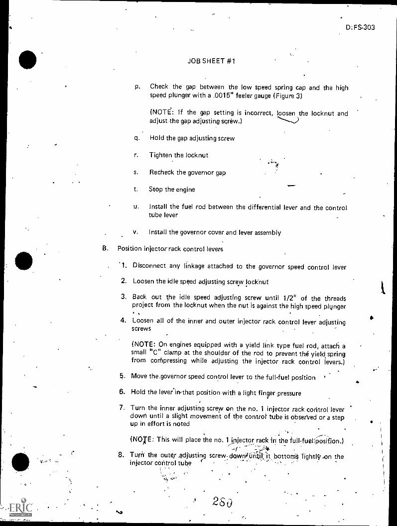
4 D:FS-303
JOB SHEET #1
p. Check the gap between the low speed spring cap and the highspeed plunger with a .0015" feeler gauge (Figure 3)
(NOTE: If the gap setting is incorrect, loosen the locknut andadjust the gap adjusting screw.)
q. Hold the gap adjusting screw
r. Tighten the locknut
s. Recheck the governor gap
t. Stop the engine
u. Install the fuel rod between the differential lever and the controltube lever
v. Install the governor cover and lever assembly
B. Position injectorrack control levers
'1. Disconnect any linkage attached to the governor speed control lever
2. Loosen the idle speed adjusting screw locknut
3. Back out the idle speed adjusting screw until 1/2" of the threadsproject from the locknut when the nut is against the high speed plunger
4. Loosen all of the inner and outer injector rack control lever adjustingscrews
(NOTE: On engines equipped with a yield link type fuel rod, attach asmall "C" clarnp at the shoulder of the rod to prevent the yield springfrom con)pressing while adjusting the injector rack control levers.)
.5. Move the,governor speed control lever to the full-fuel position '
6. Hold the lever.irpthat position with a light finger pressure
7. Turn the inner adjusting screw on the no. 1 injector rack control leverdown until a slight movement of the controt tube is obserVed or a stepup in effort is noted
(NOTE: This will place the no. 1 injector rack in the full.fuel:posifton.)
8. Turn the outey _adrusting screw dawnunI it bottorriS hghtIyon theinjector control tube
2

;
4
GOVERNORSUNIT VIII
NAME
TEST
1. Match-the terms on the right with their correct definitions.
a. Device that controls engine speed automatic-ally by varying fuel supply
b. Gradual deviation of the governed speedabove or below the desired speed
c. Change in governor rotating speed whichcauses the governor's fuel control rod to movefrom full-closed to full-open throttle positionor vice versa
d. Change in spe-ed the engine must makebefore the governor will Make a correctivemovement of the throttle
D:FS-305
1.
2.
3.
4.
Speed drift
Governor
Isochronous
Hunting'
5: Servomotor
6. Dead band
7. Speed droop
e. Oscillations in speed due to over-correction8. Flyweightsby governor
f. Piston moved by fluid under pressure
g. Holds engine speed within 1% of rated loadrpm; eliminates speed droop
h. Centrifugal ball head moving in a circular path
2. List three purposes of a governor.
a.
b.
-3. Nagle two basic types.of governors using flyweights.
a.
b.
4. Distinguish between a mechatiical governor and a hydraulic governor.
,
.28i

306
5. Name twO types of mechanical governors.
a.
b.
6. Name two types of hydraulic governors.
a.
b.
7. Match the kinds of governors on the right with their speciar functions.
a. Maintains any selected engine speed
b. A safety device which shuts down the enginein case it runs too fast
c. Limits the load to prevent overloading theengine at whatever speed it may be running
d. Adjusts the amount of load applied to engineto suit the speed at which Ft is set to run
1. Over-speed
2. Load control
3. Load limiting
4. Variable speed
8. Match the types of governors on the right with their characteristics.
a. Has large dead bands 1. Mechanical
b. Speed droop is not convenient to adjust 2. Hydraulic
c. Unavoidable speed droop
d. Is not isochronous
e. Power is small
Oir
A
_
9. Select true statements concerning the operation of the governor on load increaseby placing an 11411 in the appropriate blanks.
a. Flyweights rotate faster a
b. Speeder spring forces overcome centrifugal force of flyweights
c. Speeder rod moves down to open Juel valve to increase fuelA
10, Complete the fpllowing list of statements concerning the operation of the governoron load deceease. 0a. Flyweights rotate
b. Speeder spring force is overcome by centrifugal furceof flyweights
c. Speeder rod nioyes up forcing

to-
4
coo.
11. Identify the position of flyweights for load increase or decrease by writing Figure 1 orFigure 2 in the appropriate blanks. ,
a. Load increase
b. Load decreaseIncreased Centrifugal Force
Reduced Centrifuol Force
FIGURE 2
Spring Force(Increased)
Higher SpeedNormal Speed
Reduced Centrifigal Force
I!°Lfteei° Spring Force
(Reduced)
Higher SpeedNormal SpeedLower Speed
12. Complete the followihg,list of characterisitics of an isochronous governor.
a. Maintains constant speed without hunting
b.
-613. Select true statements concerning characteristics of a limiting speed mechanical gover-nor.
a. Controls engine idle spee-d-
b. Limits maximum operating speed
c. Can, have 8 or 10 weights
14. Demons,trate the ability to adjust a limiting speed mechanical governor and injector, rack controj.
(NOTE: If this activity has not been accomplished prior to the test, ask your instructor-when it should be completed.)
4
1

GOVERNORSUNIT VIII
ANSWERS TO TEST
1. a. 2 e. 4y b. 1 ier f. 5
c. 7 9., 3d. 6 h. 8
2. a. Maintains a selected speedb. Limits the slow and fast speedc. Shuts down engine when it over-speeds
3. a. Mechanicalb. Hydraulic
4. Mechanical governor uses mechanical linkage and hydraulic governor uses hydraulicpower to change engine fuel`control
5. a. Limiting speedb. Variable speed
6. a. Permanent speed droopb. Temporary speed droop
`7. a. 4b. 1
c. 3d, . 2
8. a. 1
b. 2c. 1
9: b, c
d. 2e. 1
10. a. Fasterc: Fuel valve to close
11.s igure 2b. Figure 1
`.12. b. Speed droop is temporary
13. a, b_
4: Performance skills evaluated to the satisfaction of the instructor
D:FS-309


