Diesel generator set QSK60 series · PDF fileThe generator set is available listed to UL 2200,...
47
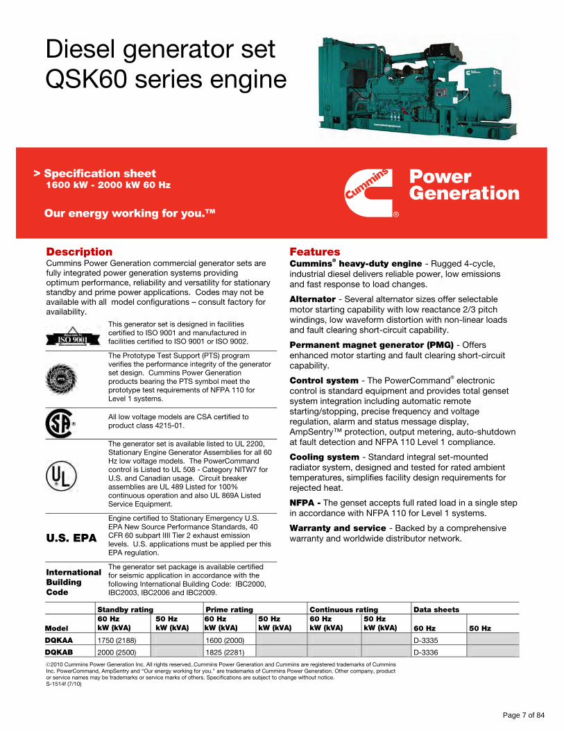
©2010 Cummins Power Generation Inc. All rights reserved..Cummins Power Generation and Cummins are registered trademarks of Cummins Inc. PowerCommand, AmpSentry and “Our energy working for you.” are trademarks of Cummins Power Generation. Other company, product or service names may be trademarks or service marks of others. Specifications are subject to change without notice. S-1514f (7/10) Diesel generator set QSK60 series engine Description Cummins Power Generation commercial generator sets are fully integrated power generation systems providing optimum performance, reliability and versatility for stationary standby and prime power applications. Codes may not be available with all model configurations – consult factory for availability. This generator set is designed in facilities certified to ISO 9001 and manufactured in facilities certified to ISO 9001 or ISO 9002. The Prototype Test Support (PTS) program verifies the performance integrity of the generator set design. Cummins Power Generation products bearing the PTS symbol meet the prototype test requirements of NFPA 110 for Level 1 systems. All low voltage models are CSA certified to product class 4215-01. The generator set is available listed to UL 2200, Stationary Engine Generator Assemblies for all 60 Hz low voltage models. The PowerCommand control is Listed to UL 508 - Category NITW7 for U.S. and Canadian usage. Circuit breaker assemblies are UL 489 Listed for 100% continuous operation and also UL 869A Listed Service Equipment. U.S. EPA Engine certified to Stationary Emergency U.S. EPA New Source Performance Standards, 40 CFR 60 subpart IIII Tier 2 exhaust emission levels. U.S. applications must be applied per this EPA regulation. Features Cummins ® heavy-duty engine - Rugged 4-cycle, industrial diesel delivers reliable power, low emissions and fast response to load changes. Alternator - Several alternator sizes offer selectable motor starting capability with low reactance 2/3 pitch windings, low waveform distortion with non-linear loads and fault clearing short-circuit capability. Permanent magnet generator (PMG) - Offers enhanced motor starting and fault clearing short-circuit capability. Control system - The PowerCommand ® electronic control is standard equipment and provides total genset system integration including automatic remote starting/stopping, precise frequency and voltage regulation, alarm and status message display, AmpSentry™ protection, output metering, auto-shutdown at fault detection and NFPA 110 Level 1 compliance. Cooling system - Standard integral set-mounted radiator system, designed and tested for rated ambient temperatures, simplifies facility design requirements for rejected heat. NFPA - The genset accepts full rated load in a single step in accordance with NFPA 110 for Level 1 systems. Warranty and service - Backed by a comprehensive warranty and worldwide distributor network. International Building Code The generator set package is available certified for seismic application in accordance with the following International Building Code: IBC2000, IBC2003, IBC2006 and IBC2009. Standby rating Prime rating Continuous rating Data sheets Model 60 Hz kW (kVA) 50 Hz kW (kVA) 60 Hz kW (kVA) 50 Hz kW (kVA) 60 Hz kW (kVA) 50 Hz kW (kVA) 60 Hz 50 Hz DQKAA 1750 (2188) 1600 (2000) D-3335 DQKAB 2000 (2500) 1825 (2281) D-3336 1600 kW - 2000 kW 60 Hz Page 7 of 84
Transcript of Diesel generator set QSK60 series · PDF fileThe generator set is available listed to UL 2200,...
©2010 Cummins Power Generation Inc. All rights reserved..Cummins Power Generation and Cummins are registered trademarks of Cummins Inc. PowerCommand, AmpSentry and “Our energy working for you.” are trademarks of Cummins Power Generation. Other company, product or service names may be trademarks or service marks of others. Specifications are subject to change without notice. S-1514f (7/10)
Diesel generator set QSK60 series engine
Description Cummins Power Generation commercial generator sets are fully integrated power generation systems providing optimum performance, reliability and versatility for stationary standby and prime power applications. Codes may not be available with all model configurations – consult factory for availability.
This generator set is designed in facilities certified to ISO 9001 and manufactured in facilities certified to ISO 9001 or ISO 9002.
The Prototype Test Support (PTS) program verifies the performance integrity of the generator set design. Cummins Power Generation products bearing the PTS symbol meet the prototype test requirements of NFPA 110 for Level 1 systems.
All low voltage models are CSA certified to product class 4215-01.
The generator set is available listed to UL 2200, Stationary Engine Generator Assemblies for all 60 Hz low voltage models. The PowerCommand control is Listed to UL 508 - Category NITW7 for U.S. and Canadian usage. Circuit breaker assemblies are UL 489 Listed for 100% continuous operation and also UL 869A Listed Service Equipment.
U.S. EPA
Engine certified to Stationary Emergency U.S. EPA New Source Performance Standards, 40 CFR 60 subpart IIII Tier 2 exhaust emission levels. U.S. applications must be applied per this EPA regulation.
Features Cummins® heavy-duty engine - Rugged 4-cycle, industrial diesel delivers reliable power, low emissions and fast response to load changes.
Alternator - Several alternator sizes offer selectable motor starting capability with low reactance 2/3 pitch windings, low waveform distortion with non-linear loads and fault clearing short-circuit capability.
Permanent magnet generator (PMG) - Offers enhanced motor starting and fault clearing short-circuit capability.
Control system - The PowerCommand® electronic control is standard equipment and provides total genset system integration including automatic remote starting/stopping, precise frequency and voltage regulation, alarm and status message display, AmpSentry™ protection, output metering, auto-shutdown at fault detection and NFPA 110 Level 1 compliance.
Cooling system - Standard integral set-mounted radiator system, designed and tested for rated ambient temperatures, simplifies facility design requirements for rejected heat.
NFPA - The genset accepts full rated load in a single step in accordance with NFPA 110 for Level 1 systems.
Warranty and service - Backed by a comprehensive warranty and worldwide distributor network.
International Building Code
The generator set package is available certified for seismic application in accordance with the following International Building Code: IBC2000, IBC2003, IBC2006 and IBC2009.
Standby rating Prime rating Continuous rating Data sheets
Model 60 Hz kW (kVA)
50 Hz kW (kVA)
60 Hz kW (kVA)
50 Hz kW (kVA)
60 Hz kW (kVA)
50 Hz kW (kVA) 60 Hz 50 Hz
DQKAA 1750 (2188) 1600 (2000) D-3335
DQKAB 2000 (2500) 1825 (2281) D-3336
1600 kW - 2000 kW 60 Hz
Page 7 of 84
ff028
Rectangle
Our energy working for you.™
www.cumminspower.com
©2010 Cummins Power Generation Inc. All rights reserved..Cummins Power Generation and Cummins are registered trademarks of Cummins Inc. PowerCommand, AmpSentry and “Our energy working for you.” are trademarks of Cummins Power Generation. Other company, product or service names may be trademarks or service marks of others. Specifications are subject to change without notice. S-1514f (7/10)
Generator set specifications Governor regulation class ISO8528 Part 1 Class G3 Voltage regulation, no load to full load ± 0.5% Random voltage variation ± 0.5% Frequency regulation Isochronous Random frequency variation ± 0.25% Radio frequency emissions compliance IEC 801.2 through IEC 801.5; MIL STD 461C, Part 9
Engine specifications Bore 158.8 mm (6.25 in) Stroke 190.0 mm (7.48 in) Displacement 60.2 litres (3673 in3) Configuration Cast iron, V 16 cylinder
Battery capacity 2200 amps minimum at ambient temperature of -18 °C to 0 °C (0 °F to 32 °F)
Battery charging alternator 40 amps Starting voltage 24 volt, negative ground Fuel system Cummins’ Modular Common Rail System
Fuel filter Dual element, 10 micron filtration, spin-on fuel filters with 15 micron water separator
Air cleaner type Dry replaceable element Lube oil filter type(s) Four spin-on, combination full flow filter and bypass filters Standard cooling system High ambient radiator
Alternator specifications Design Brushless, 4 pole, drip proof revolving field Stator 2/3 pitch Rotor Single bearing, flexible discs Insulation system Class H on low and medium voltage, Class F on high voltage Standard temperature rise 150 ºC standby at 40 °C ambient Exciter type PMG (permanent magnet generator) Phase rotation A (U), B (V), C (W) Alternator cooling Direct drive centrifugal blower fan AC waveform total harmonic distortion < 5% no load to full linear load, < 3% for any single harmonic Telephone influence factor (TIF) < 50 per NEMA MG1-22.43 Telephone harmonic factor (THF) < 3
Available voltages 60 Hz line-neutral/line-line 50 Hz line-neutral/line-line • 219/380 • 254/440
• 277/480 • 347/600
• 2400/4160 • 7200/12470
• 7620/13200 • 7970/13800
• 220/380 • 230/400
• 240/415 • 254/440
• 1905/3300 • 3640/6300
• 3810/6600 • 6350/11000
* Note: Consult factory for other voltages.
Generator set options and accessories Engine
208/240/480 V coolant heater for ambient above 4.5 °C (40 °F)
208/240/480 V coolant heater for ambient below 4.5 °C (40 °F)
Control panel 120/240 V 100 W control anti-condensation heater
Paralleling configuration Remote fault signal package Run relay package
Alternator 80 °C rise 105 °C rise 125 °C rise 120/240 V 300 W anti-condensation heater
Temperature sensor - RTDs, 2/phase
Temperature sensor – alternator bearing RTD
Differential current transformers
Exhaust system Industrial grade exhaust silencer
Residential grade exhaust silencer
Critical grade exhaust silencer
Cooling system Remote radiator
Generator set AC entrance box Battery
Battery rack with hold-down - floor standing
Circuit breaker - set mounted Disconnect switch - set mounted
PowerCommand Network Remote annunciator panel Spring isolators 2 year warranty 5 year warranty 10 year major components warranty
* Note: Some options may not be available on all models - consult factory for availability.
Page 8 of 84
ff028
Rejected
ff028
Rejected
ff028
Rejected
ff028
Rejected
ff028
Rejected
ff028
Rejected
Our energy working for you.™
www.cumminspower.com
©2010 Cummins Power Generation Inc. All rights reserved..Cummins Power Generation and Cummins are registered trademarks of Cummins Inc. PowerCommand, AmpSentry and “Our energy working for you.” are trademarks of Cummins Power Generation. Other company, product or service names may be trademarks or service marks of others. Specifications are subject to change without notice. S-1514f (7/10)
Control system PCC 3201
PowerCommand control is an integrated generator set control system providing governing, voltage regulation, engine protection and operator interface functions. Major features include: - Integral AmpSentry™ Protective Relay providing a full
range of alternator protection functions that are matched to the alternator provided.
- Battery monitoring and testing features and smart starting control system.
- Three phase sensing, full wave rectified voltage regulation system, with a PWM output for stable operation with all load types.
- Control suitable for operation in ambient temperatures from -40 °C to +70 °C (-40 °F to +158 °F) and altitudes to 5000 meters (13,000 feet).
- Prototype tested; UL, CSA, and CE compliant. - InPower™ PC-based service tool available for detailed
diagnostics. - Optional Echelon® LONWORKS
® network interface.
Operator/display panel - Off/manual/auto mode switch - Manual run/stop switch - Panel lamp test switch - Emergency stop switch - Exercise switch - Alpha-numeric display with pushbutton access for
viewing engine and alternator data and providing setup, controls and adjustments
- LED lamps indicating not in auto, common warning, common shutdown, remote start
- Configurable for local language
Engine protection - Overspeed shut down - Low oil pressure warning and shut down - High coolant temperature warning and shut down - High oil temperature warning - Low coolant level warning or shut down - Low coolant temperature warning - High and low battery voltage warning - Weak battery warning - Dead battery shut down - Fail to start (overcrank) shut down - Fail to crank shut down - Redundant start disconnect - Cranking lockout - Sensor failure indication
Engine data - DC voltage - Lube oil pressure - Coolant temperature - Lube oil temperature - Engine speed - Engine ECM data
AmpSentry AC protection - Over current and short-circuit shut down - Over current warning - Single and three phase fault regulation - Over and under voltage shut down - Over and under frequency shut down - Overload warning with alarm contact - Reverse power and reverse Var shut down
Alternator data - Line-to-line and line-to-neutral AC volts - Three phase AC current - Frequency - Total and individual phase power factor, kW and kVA - Bus voltage and frequency (with paralleling options)
Other data - Genset model data - Start attempts, starts, running hours - kW hours (total and since reset) - Fault history - Load profile (accessible with InPower)
Governing - Digital electronic isochronous governor - Temperature dynamic governing - Smart idle speed mode
Voltage regulation - Digital PWM electronic voltage regulation - Three phase line-to-neutral sensing - Single and three phase fault regulation - Configurable torque matching
Control functions - Data logging on faults - Fault simulation (requires InPower) - Time delay start and cooldown - Cycle cranking - Configurable customer outputs (4) - Configurable network inputs (8) and outputs (16) (with
optional network) - Remote emergency stop
Paralleling (Option) - Active digital phase lock loop synchronizer - Isochronous kW and kVar load sharing controls - kW import/export and kVar/PF control for utility (mains)
paralleling
Options Thermostatically controlled space heater Key-type mode switch Ground fault module Auxiliary relays (3) Echelon LONWORKS interface Modion Gateway to convert to Modbus (loose) PowerCommand iWatch web server for remote monitoring and alarm notification (loose)
Digital input and output module(s) (loose) Remote annunciator (loose) Paralleling Power transfer control
For further detail see document S-1444.
Page 9 of 84
ff028
Rejected
ff028
Rejected
Our energy working for you.™
www.cumminspower.com
©2010 Cummins Power Generation Inc. All rights reserved..Cummins Power Generation and Cummins are registered trademarks of Cummins Inc. PowerCommand, AmpSentry and “Our energy working for you.” are trademarks of Cummins Power Generation. Other company, product or service names may be trademarks or service marks of others. Specifications are subject to change without notice. S-1514f (7/10)
Ratings definitions
Emergency standby power (ESP): Applicable for supplying power to varying electrical load for the duration of power interruption of a reliable utility source. Emergency Standby Power (ESP) is in accordance with ISO 8528. Fuel Stop power in accordance with ISO 3046, AS 2789, DIN 6271 and BS 5514.
Limited-time running power (LTP): Applicable for supplying power to a constant electrical load for limited hours. Limited Time Running Power (LTP) is in accordance with ISO 8528.
Prime power (PRP): Applicable for supplying power to varying electrical load for unlimited hours. Prime Power (PRP) is in accordance with ISO 8528. Ten percent overload capability is available in accordance with ISO 3046, AS 2789, DIN 6271 and BS 5514.
Base load (continuous) power (COP): Applicable for supplying power continuously to a constant electrical load for unlimited hours. Continuous Power (COP) in accordance with ISO 8528, ISO 3046, AS 2789, DIN 6271 and BS 5514.
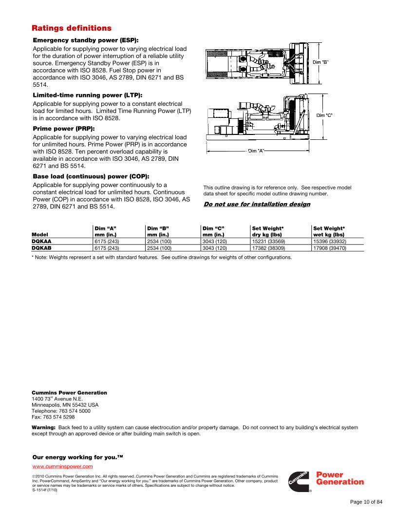
This outline drawing is for reference only. See respective model data sheet for specific model outline drawing number.
Do not use for installation design
Model Dim “A” mm (in.)
Dim “B” mm (in.)
Dim “C” mm (in.)
Set Weight* dry kg (lbs)
Set Weight* wet kg (lbs)
DQKAA 6175 (243) 2534 (100) 3043 (120) 15231 (33569) 15396 (33932) DQKAB 6175 (243) 2534 (100) 3043 (120) 17382 (38309) 17908 (39470)
* Note: Weights represent a set with standard features. See outline drawings for weights of other configurations.
Cummins Power Generation 1400 73rd Avenue N.E. Minneapolis, MN 55432 USA Telephone: 763 574 5000 Fax: 763 574 5298
Warning: Back feed to a utility system can cause electrocution and/or property damage. Do not connect to any building’s electrical system except through an approved device or after building main switch is open.
Page 10 of 84
ff028
Rectangle
ff028
Rectangle
©2010 Cummins Power Generation Inc. All rights reserved. Cummins Power Generation and Cummins are registered trademarks of Cummins Inc. “Our energy working for you.” is a trademark of Cummins Power Generation. Specifications are subject to change without notice. D-3336g (7/10)
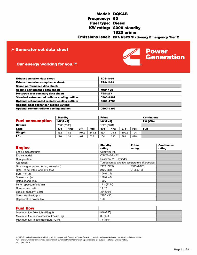
Model: DQKAB Frequency: 60 Fuel type: Diesel KW rating: 2000 standby 1825 prime Emissions level: EPA NSPS Stationary Emergency Tier 2
Exhaust emission data sheet: EDS-1065 Exhaust emission compliance sheet: EPA-1099 Sound performance data sheet: Cooling performance data sheet: MCP-158 Prototype test summary data sheet: PTS-267 Standard set-mounted radiator cooling outline: 0500-4392 Optional set-mounted radiator cooling outline: 0500-4780 Optional heat exchanger cooling outline: Optional remote radiator cooling outline: 0500-4393
Standby Prime Continuous Fuel consumption kW (kVA) kW (kVA) kW (kVA) Ratings 2000 (2500) 1825 (2281) Load 1/4 1/2 3/4 Full 1/4 1/2 3/4 Full Full US gph 46.5 82 107.3 141.3 43.4 75.1 100.6 124.1 L/hr 176 311 407 535 164 285 381 470
Engine Standby rating
Prime rating
Continuous rating
Engine manufacturer Cummins Inc.
Engine model QSK60-G6 NR2
Configuration Cast iron, V 16 cylinder
Aspiration Turbocharged and low temperature aftercooled
Gross engine power output, kWm (bhp) 2179 (2922) 1975 (2647)
BMEP at set rated load, kPa (psi) 2420 (350) 2185 (316)
Bore, mm (in) 159 (6.25)
Stroke, mm (in) 190 (7.48)
Rated speed, rpm 1800
Piston speed, m/s (ft/min) 11.4 (2244)
Compression ratio 14.5:1
Lube oil capacity, L (qt) 334 (304)
Overspeed limit, rpm 2100 ±50
Regenerative power, kW 168
Fuel flow
Maximum fuel flow, L/hr (US gph) 946 (250)
Maximum fuel inlet restriction, kPa (in Hg) 30 (9.0)
Maximum fuel inlet temperature, °C (°F) 71 (160)
Generator set data sheet
Page 11 of 84
ff028
Rectangle
Our energy working for you.™
www.cumminspower.com
©2010 Cummins Power Generation Inc. All rights reserved. Cummins Power Generation and Cummins are registered trademarks of Cummins Inc. “Our energy working for you.” is a trademark of Cummins Power Generation. Specifications are subject to change without notice. D-3336g (7/10)
Air Standby rating
Prime rating
Continuous rating
Combustion air, m3/min (scfm) 178 (6295) 159 (5615)
Maximum air cleaner restriction, kPa (in H2O) 6.2 (25)
Alternator cooling air, m3/min (cfm) 204 (7300)
Exhaust Exhaust flow at set rated load, m3/min (cfm) 436 (15385) 385 (13580)
Exhaust temperature, °C (°F) 488 (900) 466 (870)
Maximum back pressure, kPa (in H2O) 6.8 (27)
Standard set-mounted radiator cooling Ambient design, °C ( °F) 40 (104)
Fan load, kWm (HP) 57 (77)
Coolant capacity (with radiator), L (US gal) 492 (130)
Cooling system air flow, m3/min (scfm) 1922 (67870)
Total heat rejection, MJ/min (Btu/min) 99.5 (94395) 91.0 (86382)
Maximum cooling air flow static restriction, kPa (in H2O) 0.12 (0.5)
Maximum fuel return line restriction kPa (in Hg) 30 (9.0)
Optional set-mounted radiator cooling
Ambient design, °C (°F) 50 (122)
Fan load, kWm (HP) 57 (77)
Coolant capacity (with radiator), L (US gal) 163 (43)
Cooling system air flow, m3/min (scfm) 2795 (98700)
Total heat rejection, MJ/min (Btu/min) 99.5 (94395) 91 (86382)
Maximum cooling air flow static restriction, kPa (in H2O) 0.12 (0.5)
Maximum fuel return line restriction, kPa (in Hg) 30 (9.0)
Optional heat exchanger cooling
Set coolant capacity, L (US gal) Heat rejected, jacket water circuit, MJ/min (Btu/min) Heat rejected, aftercooler circuit, MJ/min (Btu/min) Heat rejected, fuel circuit, MJ/min (Btu/min) Total heat radiated to room, MJ/min (Btu/min) Maximum raw water pressure, jacket water circuit, kPa (psi) Maximum raw water pressure, aftercooler circuit, kPa (psi) Maximum raw water pressure, fuel circuit, kPa (psi) Maximum raw water flow, jacket water circuit, L/min (US gal/min) Maximum raw water flow, aftercooler circuit, L/min (US gal/min) Maximum raw water flow, fuel circuit, L/min (US gal/min) Minimum raw water flow at 27 °C (80 °F) inlet temp, jacket water circuit, L/min (US gal/min)
Minimum raw water flow at 27 °C (80 °F) inlet temp, aftercooler circuit, L/min (US gal/min)
Minimum raw water flow at 27 °C (80 °F) inlet temp, fuel circuit, L/min (US gal/min)
Raw water delta P at min flow, jacket water circuit, kPa (psi) Raw water delta P at min flow, aftercooler circuit, kPa (psi) Raw water delta P at min flow, fuel circuit, kPa (psi) Maximum jacket water outlet temp, °C (°F) Maximum aftercooler inlet temp, °C (°F) Maximum aftercooler inlet temp at 25 °C (77 °F) ambient, °C ( °F) Maximum fuel return line restriction, kPa (in Hg)
Page 12 of 84
Our energy working for you.™
www.cumminspower.com
©2010 Cummins Power Generation Inc. All rights reserved. Cummins Power Generation and Cummins are registered trademarks of Cummins Inc. “Our energy working for you.” is a trademark of Cummins Power Generation. Specifications are subject to change without notice. D-3336g (7/10)
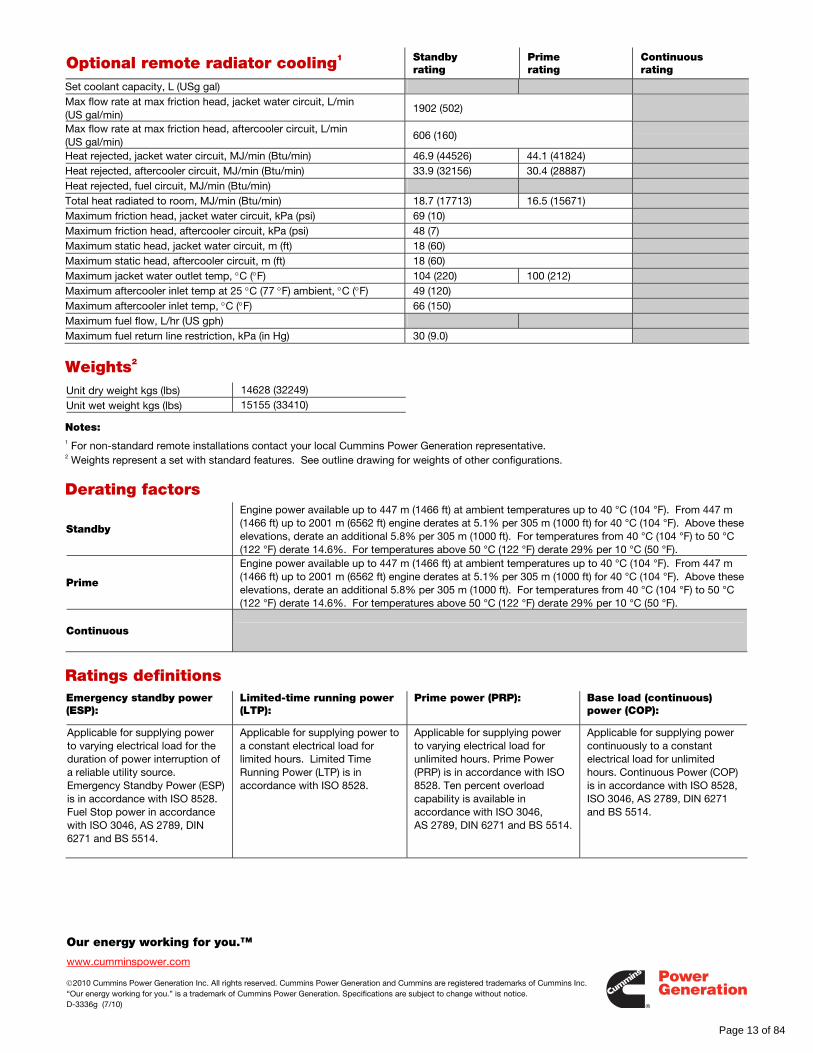
Optional remote radiator cooling1 Standby rating
Prime rating
Continuous rating
Set coolant capacity, L (USg gal) Max flow rate at max friction head, jacket water circuit, L/min (US gal/min)
1902 (502)
Max flow rate at max friction head, aftercooler circuit, L/min (US gal/min)
606 (160)
Heat rejected, jacket water circuit, MJ/min (Btu/min) 46.9 (44526) 44.1 (41824) Heat rejected, aftercooler circuit, MJ/min (Btu/min) 33.9 (32156) 30.4 (28887) Heat rejected, fuel circuit, MJ/min (Btu/min) Total heat radiated to room, MJ/min (Btu/min) 18.7 (17713) 16.5 (15671) Maximum friction head, jacket water circuit, kPa (psi) 69 (10) Maximum friction head, aftercooler circuit, kPa (psi) 48 (7) Maximum static head, jacket water circuit, m (ft) 18 (60) Maximum static head, aftercooler circuit, m (ft) 18 (60) Maximum jacket water outlet temp, °C (°F) 104 (220) 100 (212) Maximum aftercooler inlet temp at 25 °C (77 °F) ambient, °C (°F) 49 (120) Maximum aftercooler inlet temp, °C (°F) 66 (150) Maximum fuel flow, L/hr (US gph) Maximum fuel return line restriction, kPa (in Hg) 30 (9.0)
Weights2
Unit dry weight kgs (lbs) 14628 (32249)
Unit wet weight kgs (lbs) 15155 (33410)
Notes: 1 For non-standard remote installations contact your local Cummins Power Generation representative. 2 Weights represent a set with standard features. See outline drawing for weights of other configurations.
Derating factors
Standby
Engine power available up to 447 m (1466 ft) at ambient temperatures up to 40 °C (104 °F). From 447 m (1466 ft) up to 2001 m (6562 ft) engine derates at 5.1% per 305 m (1000 ft) for 40 °C (104 °F). Above these elevations, derate an additional 5.8% per 305 m (1000 ft). For temperatures from 40 °C (104 °F) to 50 °C (122 °F) derate 14.6%. For temperatures above 50 °C (122 °F) derate 29% per 10 °C (50 °F).
Prime
Engine power available up to 447 m (1466 ft) at ambient temperatures up to 40 °C (104 °F). From 447 m (1466 ft) up to 2001 m (6562 ft) engine derates at 5.1% per 305 m (1000 ft) for 40 °C (104 °F). Above these elevations, derate an additional 5.8% per 305 m (1000 ft). For temperatures from 40 °C (104 °F) to 50 °C (122 °F) derate 14.6%. For temperatures above 50 °C (122 °F) derate 29% per 10 °C (50 °F).
Continuous
Ratings definitions Emergency standby power (ESP):
Limited-time running power (LTP):
Prime power (PRP):
Base load (continuous) power (COP):
Applicable for supplying power to varying electrical load for the duration of power interruption of a reliable utility source. Emergency Standby Power (ESP) is in accordance with ISO 8528. Fuel Stop power in accordance with ISO 3046, AS 2789, DIN 6271 and BS 5514.
Applicable for supplying power to a constant electrical load for limited hours. Limited Time Running Power (LTP) is in accordance with ISO 8528.
Applicable for supplying power to varying electrical load for unlimited hours. Prime Power (PRP) is in accordance with ISO 8528. Ten percent overload capability is available in accordance with ISO 3046, AS 2789, DIN 6271 and BS 5514.
Applicable for supplying power continuously to a constant electrical load for unlimited hours. Continuous Power (COP) is in accordance with ISO 8528, ISO 3046, AS 2789, DIN 6271 and BS 5514.
Page 13 of 84
Our energy working for you.™
www.cumminspower.com
©2010 Cummins Power Generation Inc. All rights reserved. Cummins Power Generation and Cummins are registered trademarks of Cummins Inc. “Our energy working for you.” is a trademark of Cummins Power Generation. Specifications are subject to change without notice. D-3336g (7/10)
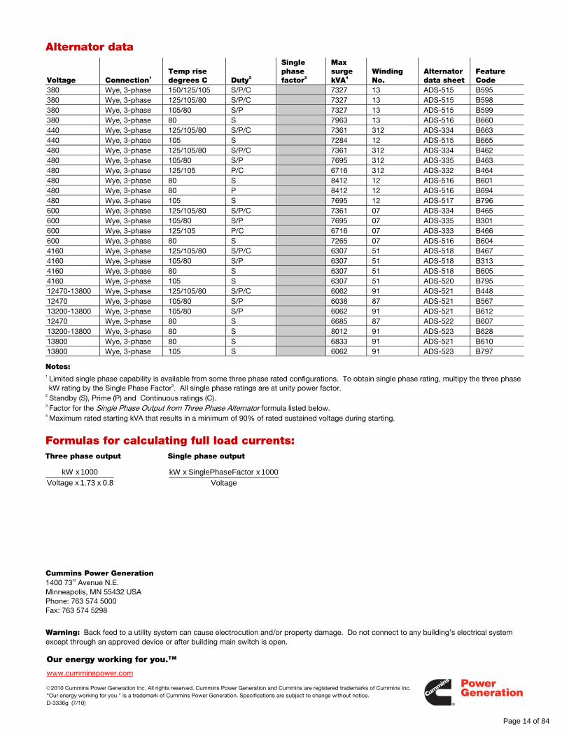
Alternator data
Voltage Connection1 Temp rise degrees C Duty2
Single phase factor3
Max surge kVA4
Winding No.
Alternator data sheet
Feature Code
380 Wye, 3-phase 150/125/105 S/P/C 7327 13 ADS-515 B595 380 Wye, 3-phase 125/105/80 S/P/C 7327 13 ADS-515 B598 380 Wye, 3-phase 105/80 S/P 7327 13 ADS-515 B599 380 Wye, 3-phase 80 S 7963 13 ADS-516 B660 440 Wye, 3-phase 125/105/80 S/P/C 7361 312 ADS-334 B663 440 Wye, 3-phase 105 S 7284 12 ADS-515 B665 480 Wye, 3-phase 125/105/80 S/P/C 7361 312 ADS-334 B462 480 Wye, 3-phase 105/80 S/P 7695 312 ADS-335 B463 480 Wye, 3-phase 125/105 P/C 6716 312 ADS-332 B464 480 Wye, 3-phase 80 S 8412 12 ADS-516 B601 480 Wye, 3-phase 80 P 8412 12 ADS-516 B694 480 Wye, 3-phase 105 S 7695 12 ADS-517 B796 600 Wye, 3-phase 125/105/80 S/P/C 7361 07 ADS-334 B465 600 Wye, 3-phase 105/80 S/P 7695 07 ADS-335 B301 600 Wye, 3-phase 125/105 P/C 6716 07 ADS-333 B466 600 Wye, 3-phase 80 S 7265 07 ADS-516 B604 4160 Wye, 3-phase 125/105/80 S/P/C 6307 51 ADS-518 B467 4160 Wye, 3-phase 105/80 S/P 6307 51 ADS-518 B313 4160 Wye, 3-phase 80 S 6307 51 ADS-518 B605 4160 Wye, 3-phase 105 S 6307 51 ADS-520 B795 12470-13800 Wye, 3-phase 125/105/80 S/P/C 6062 91 ADS-521 B448 12470 Wye, 3-phase 105/80 S/P 6038 87 ADS-521 B567 13200-13800 Wye, 3-phase 105/80 S/P 6062 91 ADS-521 B612 12470 Wye, 3-phase 80 S 6685 87 ADS-522 B607 13200-13800 Wye, 3-phase 80 S 8012 91 ADS-523 B628 13800 Wye, 3-phase 80 S 6833 91 ADS-521 B610 13800 Wye, 3-phase 105 S 6062 91 ADS-523 B797
Notes: 1 Limited single phase capability is available from some three phase rated configurations. To obtain single phase rating, multipy the three phase kW rating by the Single Phase Factor3. All single phase ratings are at unity power factor.
2 Standby (S), Prime (P) and Continuous ratings (C).
3 Factor for the Single Phase Output from Three Phase Alternator formula listed below.
4 Maximum rated starting kVA that results in a minimum of 90% of rated sustained voltage during starting.
Formulas for calculating full load currents: Three phase output Single phase output
Cummins Power Generation 1400 73rd Avenue N.E. Minneapolis, MN 55432 USA Phone: 763 574 5000 Fax: 763 574 5298
Warning: Back feed to a utility system can cause electrocution and/or property damage. Do not connect to any building’s electrical system except through an approved device or after building main switch is open.
Voltage
1000 x eFactorSinglePhas x kW
0.8 x 1.73 x Voltage
1000 x kW
Page 14 of 84
ff028
Rectangle
©2008|Cummins Power Generation Inc.|All rights reserved|Specifications subject to change without notice|Cummins Power Generation and Cummins are registered trademarks of Cummins Inc. PowerCommand, InPower, AmpSentry, iWatch and “Our energy working for you.” are trademarks of Cummins Power Generation. Other company, product, or service names may be trademarks or service marks of others. S-1444h (4/08) Page 1 of 10
PowerCommand® 3201 digital generator set control
Description The PowerCommand® 3201 Control is a microprocessor-based generator set monitoring, metering and control system. The control provides an operator interface to the genset, digital voltage regulation, digital governing and generator set protective functions. It may incorporate optional automatic digital paralleling controls and/or power transfer controls. The integration of all the functions into a single control system provides enhanced reliability and performance compared to conventional control systems.
The PowerCommand control is designed for mounting on the generator set and is suitable for use on generator sets ranging in size from 20 kW to 4000 kW. It will directly read AC voltages up to 600 VAC and can be configured for any frequency, voltage and power connection configuration from 120 to 13,800 VAC. The operator panel may be remote-mounted from the generator set and connected via an RS485 network connection.
The control offers a wide range of standard control and digital display features so custom control configurations are not needed to meet application requirements and system reliability is not compromised by use of untested special components.
Power for PowerCommand Control is usually derived from the generator set starting batteries. It functions over a voltage range from 8 VDC to 35 VDC.
Features Digital full authority electronic engine controls - Provide engine monitoring, protection and governing. These functions are integrated with voltage regulation and paralleling functions for optimum system performance.
Digital voltage regulation - Provides fast, controlled response to load changes and high levels of immunity to the effects of non-linear loads.
AmpSentry™ protective relay - UL Listed, true alternator overcurrent protection.
AC output metering - Includes analog and digital display.
Battery monitoring system - Senses and warns against weak battery condition that is not detected by conventional DC over and undervoltage monitoring.
Message display - Digital alarm and status.
Generator set monitoring - Displays status of all critical engine and alternator generator set functions.
Smart starting control system - Integrated fuel ramping to limit black smoke and frequency overshoot, in addition to optimized cold weather starting.
Advanced serviceability - Utilizes InPower™, a PC-based software service tool.
Digital power transfer control - Optional control functions that allow operation in open transition, closed transition or soft (ramping) transfer modes.
PowerCommand LonWorks® network - Optional network interface providing expanded input/output capability, remote monitoring and control by annunciators and other equipment, and easier installation.
Warranty - Backed by a comprehensive warranty and worldwide distributor service network.
Page 15 of 84
Our energy working for you.™
www.cumminspower.com
©2008|Cummins Power Generation Inc.|All rights reserved|Specifications subject to change without notice|Cummins Power Generation and Cummins are registered trademarks of Cummins Inc. PowerCommand, InPower, AmpSentry, iWatch and “Our energy working for you.” are trademarks of Cummins Power Generation. Other company, product, or service names may be trademarks or service marks of others. S-1444h (4/08) Page 2 of 10
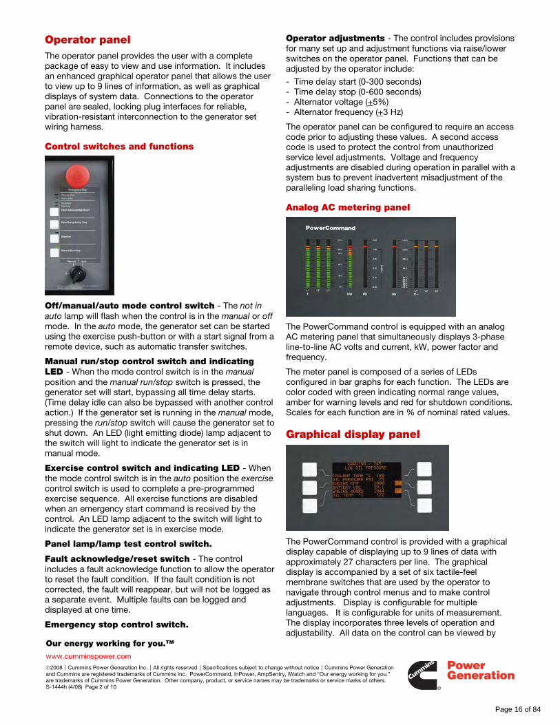
Operator panel The operator panel provides the user with a complete package of easy to view and use information. It includes an enhanced graphical operator panel that allows the user to view up to 9 lines of information, as well as graphical displays of system data. Connections to the operator panel are sealed, locking plug interfaces for reliable, vibration-resistant interconnection to the generator set wiring harness.
Control switches and functions
Off/manual/auto mode control switch - The not in auto lamp will flash when the control is in the manual or off mode. In the auto mode, the generator set can be started using the exercise push-button or with a start signal from a remote device, such as automatic transfer switches.
Manual run/stop control switch and indicating LED - When the mode control switch is in the manual position and the manual run/stop switch is pressed, the generator set will start, bypassing all time delay starts. (Time delay idle can also be bypassed with another control action.) If the generator set is running in the manual mode, pressing the run/stop switch will cause the generator set to shut down. An LED (light emitting diode) lamp adjacent to the switch will light to indicate the generator set is in manual mode.
Exercise control switch and indicating LED - When the mode control switch is in the auto position the exercise control switch is used to complete a pre-programmed exercise sequence. All exercise functions are disabled when an emergency start command is received by the control. An LED lamp adjacent to the switch will light to indicate the generator set is in exercise mode.
Panel lamp/lamp test control switch.
Fault acknowledge/reset switch - The control includes a fault acknowledge function to allow the operator to reset the fault condition. If the fault condition is not corrected, the fault will reappear, but will not be logged as a separate event. Multiple faults can be logged and displayed at one time.
Emergency stop control switch.
Operator adjustments - The control includes provisions for many set up and adjustment functions via raise/lower switches on the operator panel. Functions that can be adjusted by the operator include:
- Time delay start (0-300 seconds) - Time delay stop (0-600 seconds) - Alternator voltage (+5%) - Alternator frequency (+3 Hz)
The operator panel can be configured to require an access code prior to adjusting these values. A second access code is used to protect the control from unauthorized service level adjustments. Voltage and frequency adjustments are disabled during operation in parallel with a system bus to prevent inadvertent misadjustment of the paralleling load sharing functions.
Analog AC metering panel
The PowerCommand control is equipped with an analog AC metering panel that simultaneously displays 3-phase line-to-line AC volts and current, kW, power factor and frequency.
The meter panel is composed of a series of LEDs configured in bar graphs for each function. The LEDs are color coded with green indicating normal range values, amber for warning levels and red for shutdown conditions. Scales for each function are in % of nominal rated values.
Graphical display panel
The PowerCommand control is provided with a graphical display capable of displaying up to 9 lines of data with approximately 27 characters per line. The graphical display is accompanied by a set of six tactile-feel membrane switches that are used by the operator to navigate through control menus and to make control adjustments. Display is configurable for multiple languages. It is configurable for units of measurement. The display incorporates three levels of operation and adjustability. All data on the control can be viewed by
Page 16 of 84
Our energy working for you.™
www.cumminspower.com
©2008|Cummins Power Generation Inc.|All rights reserved|Specifications subject to change without notice|Cummins Power Generation and Cummins are registered trademarks of Cummins Inc. PowerCommand, InPower, AmpSentry, iWatch and “Our energy working for you.” are trademarks of Cummins Power Generation. Other company, product, or service names may be trademarks or service marks of others. S-1444h (4/08) Page 3 of 10
scrolling through screens with the navigation keys. The top three lines of the display are allocated to mode and status messages that continuously display the operating mode of the control system, as well as any faults or warning conditions that may be present on the controller. If more than one fault or warning message is present, the messages will scroll to allow the operator to view all active messages in the system.
Screen-saver mode - The operator panel can be programmed to automatically switch off to reduce battery voltage drain when the control is not being used and the generator set is not running. Depressing any button on the operator panel, new fault conditions or receipt of a remote signal at the control will “wake up” the control.
Generator set data
Generator set hardware data - Generator set rating in kVA, complete generator set model number and serial number, engine model and serial number and alternator model and serial number. The control also displays the part number of the control and the software version present in the control.
Data logs - Number of start attempts and number of start attempts since reset. Number of times generator set has run and number of times since reset. Duration of generator set running time and duration of running time since last reset. Generator set kWh produced and kWh produced since last reset.
Adjustment history - Record of adjustment and setting changes made on the control, identifies whether adjustment was made via the operator panel or with a service tool. If a service tool is used, the control provides a record of the serial number of the tool used. This information is read with InPower.
Fault history - Record of the most recent fault conditions with time stamp, along with the number of times each fault has occurred. At least 20 events are stored in the control memory.
Load profile data - Data indicating the total operating hours at percent of load in 10% increments and since reset.
Generator set AC data
Generator set output frequency, voltage and current - All phases (line-to-line and line-to-neutral for voltage. Accuracy 1%.
Generator set power output - PowerCommand displays generator set kW and kVA output (average phase, individual phase and direction of flow) and power factor with leading/lagging indication. Accuracy 5%.
Generator set kWh energy output - Total kWh produced and total produced since last reset with time stamp of time of last reset.
Digital synchroscope - Bus voltage and frequency, generator set bus voltage and frequency, the phase angle displacement and a signal indicating “ready to close”. A breaker control switch is included on this panel for convenient operation of the equipment without switching between viewing screens.
Engine data
Basic engine data - Engine starting battery voltage, engine lube oil pressure and engine coolant temperature.
Engine service data - Varies with engine used, but typically includes: Engine coolant pressure, engine fuel rail temperature and pressure, engine fuel input and output temperature, intake manifold temperature and pressure, ambient air pressure, crankcase blowby flow and aftercooler inlet coolant temperature.
Engine fuel consumption - The fuel consumed by the engine is calculated by the control based on fuel flow into the engine and returned by the engine, and the temperature of the two flow streams. Accuracy is + 5% over 500 hours of operation. Data provided includes overall average fuel consumed and consumption since reset. This information is read with InPower.
Engine exhaust temperature (optional).
Power transfer control data (optional)
Utility (mains) source data - Displays line-to-line and line-to-neutral voltage of utility (mains) source, frequency and estimated amps, and kW and kVA supplied by utility (mains) source (optional when power transfer control is used).
System status information - Provides graphical system status display showing availability of sources and positions of each contactor.
System control - Allows operator to view status of system and manually control operation of the system. Provides manual adjustment capability for time delay start, stop, transfer and retransfer, as well as time delays for program transition (when used) and power transfer overlap time.
Internal control functions General functions
System control voltage - The control operates on 24 VDC from the generator set starting batteries. Control functions are fully operational over a voltage range of 8 VDC to 36 VDC.
Emergency start mode - PowerCommand accepts a ground signal from remote devices or a network signal to automatically start the generator set and immediately accelerate to rated speed and voltage.
PowerCommand includes a smart starting system that is designed to quickly start the engine, minimize black smoke, minimize voltage and frequency overshoot, and
Page 17 of 84
Our energy working for you.™
www.cumminspower.com
©2008|Cummins Power Generation Inc.|All rights reserved|Specifications subject to change without notice|Cummins Power Generation and Cummins are registered trademarks of Cummins Inc. PowerCommand, InPower, AmpSentry, iWatch and “Our energy working for you.” are trademarks of Cummins Power Generation. Other company, product, or service names may be trademarks or service marks of others. S-1444h (4/08) Page 4 of 10
oscillations on starting. The control system does this by careful simultaneous control of the engine fuel system and alternator excitation system.
Non-emergency start mode - The control is provided with a separate remote start input or a network signal to start the generator set via the programmable idle control. Using the non-emergency mode, the generator set takes longer to start, but there is less wear on the engine. In this start mode, the generator set will start, operate at idle speed for a predefined time period or until the engine reaches operating temperature (whichever time is shorter), and then ramp to rated speed and voltage. Time delay is adjustable from 0-300 seconds and default is 10 seconds. The control also monitors and records the source of start signals, when that information is available. The control automatically exits idle mode if an emergency remote start signal is received at the control.
Data logging - The control maintains a record of manual control operations, warning and shutdown conditions and other events. It uses the control “on” time as the time-stamp means when a real time clock is not included with the control. The control also stores critical engine and alternator data before and after a fault occurs, for use by InPower and the technician in evaluating the root causes for the fault condition.
Fault simulation mode - PowerCommand, in conjunction with InPower software, will accept commands to allow a technician to verify the proper operation of critical protective functions of the control by simulating failure modes or by forcing the control to operate outside of its normal operating ranges. InPower also provides a complete list of faults and settings for the protective functions of the specific generator set it is communicating with.
Built in test - The control system automatically tests itself, and all the sensors, actuators and harnesses in the control system, on a startup signal. The test can also be initiated from InPower and can be accomplished either locally to the generator set or remotely.
Engine control
Engine starting - The control operates a factory-supplied fuel valve that enables engine starting.
Cycle cranking - Configurable for number of starting cycles (1 to 7) and duration of crank and rest periods. Control includes starter protection algorithms to prevent the operator from specifying a starting sequence that might be damaging. Default setting is for (3) start cycles composed of 15 seconds of cranking and 15 seconds of rest.
Programmable idle speed control - In this mode the generator set would start and run to idle speed. It would operate at that speed for a programmed time period, then ramp to rated speed. When the control gets a signal to stop, it will ramp to idle, operate for the programmed period at idle and then shut down. During idle mode,
engine protective functions are adjusted for the lower engine speed and alternator function is disabled.
Time delay start and stop (cool down) - Configurable for time delay of 0-300 seconds prior to starting after receiving a remote start signal in normal operation modes and for time delay of 0-600 seconds prior to ramp-to-idle or shutdown after signal to stop in normal operation modes. The generator set control will monitor the load during operation of the generator set, and if the total load on the set is less than 10% of rated it will reduce the operation time for the time delay stop in order to prevent extended operation of the engine at very light load levels. Default for both time delay periods is 0 seconds.
Engine governing
Isochronous governing - Controls engine speed within + 0.25% for any steady state load from no load to full load. Frequency drift will not exceed + 0.5% for a 33 °C (60 °F) change in ambient temperature over an 8 hour period.
Droop governing - Control can be adjusted to droop from 0 to 10% from no load to full load, using InPower.
Temperature dynamics - Modifies the engine fuel system control parameters as a function of engine temperature. Allows engine to be more responsive when warm and more stable when operating at lower temperature levels.
Isochronous load sharing control - See Paralleling Functions/Load sharing controls.
Droop load sharing control - See Paralleling Functions/Load sharing controls.
Idle mode - Engine governing can be regulated at an idle speed for a programmed period on start or stop of the engine. When the engine is operating at idle speed, the alternator excitation is automatically switched off.
Alternator control
Digital output voltage regulation - PowerCommand will regulate output voltage to within 0.5% for any loads between no load and full load. Voltage drift will not exceed + 0.5% for a 33 °C (60 °F) change in temperature in an 8 hour period. On engine starting, or sudden load acceptance, voltage is controlled to a maximum of 5% overshoot over nominal level.
Torque-matched V/Hz overload control - The voltage roll-off set point and rate of decay (i.e., the slope of the V/Hz curve) is adjustable in the control. This function is automatically disabled when the control is in a synchronizing mode.
Fault current regulation - PowerCommand will regulate the output current on any phase to a maximum of 3 times rated current under fault conditions for both single phase and three phase faults. In conjunction with a permanent magnet generator, it will provide 3 times rated current on all phases for motor starting and short circuit coordination purposes.
Page 18 of 84
Our energy working for you.™
www.cumminspower.com
©2008|Cummins Power Generation Inc.|All rights reserved|Specifications subject to change without notice|Cummins Power Generation and Cummins are registered trademarks of Cummins Inc. PowerCommand, InPower, AmpSentry, iWatch and “Our energy working for you.” are trademarks of Cummins Power Generation. Other company, product, or service names may be trademarks or service marks of others. S-1444h (4/08) Page 5 of 10
Isochronous (kVar) load sharing control - See Paralleling Functions/Load sharing controls.
Droop (kVar) load sharing control - See Paralleling Functions/Load sharing controls.
Protective functions On a warning condition, the control will indicate a fault by lighting the warning LED on the control panel and displaying the fault name and code on the operator display panel. The nature of the fault and time of occurrence are logged in the control. The service manual and InPower service tool provide service keys and procedures based on the service codes provided.
On a shutdown condition, the control will light the shutdown LED on the control panel, display the fault name and code, initiate shutdown and lock out the generator set. The shutdown sequence of the generator set includes programmable cooldown at idle for fault conditions that do not endanger the engine. The control maintains a data log of all fault conditions as they occur and time stamps them with the controller run time and engine operating hours data. Adjustments to most set points are made using the InPower service tool.
The control system includes a “fault bypass” mode that forces the system to function regardless of the status of protective functions. In this mode, the only protective functions that are operational are over speed, loss of both speed sensors, moving the control switch to the off position or pressing the emergency stop switch. The control maintains a record of the time that the mode is enabled and of all warning or shutdown conditions that have occurred while in the “fault bypass” mode.
Many protective functions within the control system are configurable for warning, shutdown or both (2 levels). Exceptions to this include functions such as over speed conditions, and loss of speed sensing. In addition, some warning functions can incorporate control functions as a consequence of a fault.
System protective functions:
Ground fault warning (option - 600 VAC class generator sets) - Ground (earth) fault sensing is adjustable over a range of 100-1200 amps with time delays of 0-1 second. May be configured for shutdown rather than alarm.
Configurable alarm and status inputs - PowerCommand will accept up to four alarm or status inputs (contact closed to ground) to indicate customer-specified conditions. The control is programmable for warning, shutdown or status indication and for labeling the input (up to 24 characters). Sixteen additional faults can be input to the control via the network.
Breaker fail to close and breaker auxiliary contact warning or shutdown - When the paralleling control signals a circuit breaker to close, it will monitor the breaker
auxiliary contacts and verify that the breaker has connected the generator set to the system bus. If the control does not sense a breaker closure within 0.5 second of the close signal, the control will monitor the phase relationship between the generator set and the bus. If this indicates that the generator set is not closed to the bus, the “breaker fail to close” alarm will be indicated, the breaker will be opened and the generator set shut down. If the phase relationship monitor indicates that the generator set is in parallel with the bus, “circuit breaker auxiliary contact failure” will be indicated and the generator set will continue to run in normal operation mode.
Breaker fail to open warning - The control system monitors the operation of breakers that have been signaled to open. If the breaker does not open within 1 second of initiation of signal, a “breaker fail to open” warning is initiated. The control will logically allow the generator set to continue to run if shutdown of the generator set with the breaker closed will cause potential damage or operating problems.
Bus or generator set PT input calibration error - The control system monitors the sensed voltage from the bus and generator set output voltage-potential transformers. When the paralleling breaker is closed, it will indicate a warning condition when they read different values.
Emergency stop - Annunciated whenever the local or remote emergency stop signal is received. Alarm panel distinguishes between local or remote operation.
AmpSentry protective relay
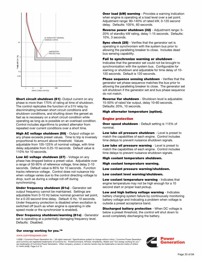
AmpSentry protective relay is a UL Listed comprehensive monitoring and control system integral to the PowerCommand Control System that guards the electrical integrity of the alternator and power system by providing protection against a wide array of fault conditions in the generator set or in the load. It also provides single and three phase fault current regulation so that downstream protective devices have the maximum current available to quickly clear fault conditions without subjecting the alternator to potentially catastrophic failure conditions. See document R1053 below for a full size time over current curve. The control does not include protection required for interconnection to a utility (mains) service.
Over current warning - Output current on any phase at more than 110% of rating for more than 60 seconds.
Over current shutdown (51V) - Output current on any phase is more than 110%, less than 175% of rating and approaching thermal damage point of alternator. Control includes algorithms to protect alternator from repeated over current conditions over a short period of time. The control does not include instantaneous trip functions, as they are not necessary for alternator protection and complicate short circuit coordination (discrimination).
Page 19 of 84
Our energy working for you.™
www.cumminspower.com
©2008|Cummins Power Generation Inc.|All rights reserved|Specifications subject to change without notice|Cummins Power Generation and Cummins are registered trademarks of Cummins Inc. PowerCommand, InPower, AmpSentry, iWatch and “Our energy working for you.” are trademarks of Cummins Power Generation. Other company, product, or service names may be trademarks or service marks of others. S-1444h (4/08) Page 6 of 10
Short circuit shutdown (51) -Output current on any phase is more than 175% of rating at time of shutdown. The control replicates the function of a 51V relay by discriminating between short circuit conditions and shutdown conditions, and shutting down the genset as fast as is necessary on a short circuit condition while operating as long as is possible on an overload condition. Control includes algorithms to protect alternator from repeated over current conditions over a short time.
High AC voltage shutdown (59) - Output voltage on any phase exceeds preset values. Time to trip is inversely proportional to amount above threshold. Values adjustable from 105-125% of nominal voltage, with time delay adjustable from 0.25-10 seconds. Default value is 110% for 10 seconds.
Low AC voltage shutdown (27) - Voltage on any phase has dropped below a preset value. Adjustable over a range of 50-95% of reference voltage, time delay 2-10 seconds. Default value is 85% for 10 seconds. Function tracks reference voltage. Control does not nuisance trip when voltage varies due to the control directing voltage to drop, such as during a voltage roll-off during synchronizing.
Under frequency shutdown (81u) - Generator set output frequency cannot be maintained. Settings are adjustable from 0-10 Hz below nominal governor set point, for a 0-20 second time delay. Default: 6 Hz, 10 seconds. Under frequency protection is disabled when excitation is switched off (such as when engine is operating in idle speed mode or the synchronizer is enabled).
Over frequency shutdown/warning (81o) - Generator set is operating at a potentially damaging frequency level. Defaults: Disabled.
Over load (kW) warning - Provides a warning indication when engine is operating at a load level over a set point. Adjustment range: 80-140% of rated kW, 0-120 second delay. Defaults: 105%, 60 seconds.
Reverse power shutdown (32) - Adjustment range: 5-20% of standby kW rating, delay 1-15 seconds. Defaults: 10%, 3 seconds.
Sync check (25) - Verifies that the generator set is operating in synchronism with the system bus prior to allowing the paralleling breaker to close. Includes dead bus sensing capability.
Fail to synchronize warning or shutdown - Indicates that the generator set could not be brought to synchronization with the system bus. Configurable for warning or shutdown and adjustable for time delay of 10-120 seconds. Default is 120 seconds.
Phase sequence sensing shutdown - Verifies that the generator set phase sequence matches the bus prior to allowing the paralleling breaker to close. The generator set will shutdown if the generator set and bus phase sequence do not match.
Reverse Var shutdown - Shutdown level is adjustable: 15-50% of rated Var output, delay 10-60 seconds. Defaults: 20%, 10 seconds.
High alternator temperature (option).
Engine protection
Over speed shutdown - Default setting is 115% of nominal.
Low lube oil pressure shutdown - Level is preset to match the capabilities of each engine. Control includes time delays to prevent nuisance shutdown signals.
Low lube oil pressure warning - Level is preset to match the capabilities of each engine. Control includes time delays to prevent nuisance shutdown signals.
High coolant temperature shutdown.
High coolant temperature warning.
Low coolant pressure warning/shutdown.
Low coolant level warning/shutdown.
Low coolant temperature warning - Indicates that engine temperature may not be high enough for a 10 second start or proper load pickup.
Low and high battery voltage warning - Indicates battery charging system failure by continuously monitoring battery voltage and indicating a problem when voltage is outside a preset acceptance band.
Discharged battery protection - When DC voltage is below a preset threshold, the control will shut down to avoid completely discharging the battery.
10
1
0.1
0.05
1 103
AMPS (TIMES RATED)
ALTERNATOR THERMAL DAMAGE CURVE
AMPSENTRY PROTECTION
100
Page 20 of 84

Our energy working for you.™
www.cumminspower.com
©2008|Cummins Power Generation Inc.|All rights reserved|Specifications subject to change without notice|Cummins Power Generation and Cummins are registered trademarks of Cummins Inc. PowerCommand, InPower, AmpSentry, iWatch and “Our energy working for you.” are trademarks of Cummins Power Generation. Other company, product, or service names may be trademarks or service marks of others. S-1444h (4/08) Page 7 of 10
Weak battery warning - The control system will test the battery bank each time the generator set is signaled to start and indicate a warning if the generator set battery indicates impending failure.
Fail to start (overcrank) shutdown.
Fail to crank shutdown - Control has signaled starter to crank engine but engine does not rotate.
Redundant starter disconnect.
Redundant speed sensors - Loss of one sensor results in a mag pickup sensor warning. Loss of both sensors results in mag pickup failure.
Low fuel day tank and low fuel main tank warning.
Cranking lockout - The control will not allow the starter to attempt to engage or to crank the engine when the engine is rotating.
Sensor failure indication - All analog sensors are provided with sensor failure logic to indicate if the sensor or interconnecting wiring has failed. Separate indication is provided for fail high or low.
High crankcase blowby level warning.
High fuel temperature warning.
High intake manifold temperature/pressure.
Aftercooler cooler inlet over temperature.
Paralleling functions (optional) First Start Sensor™ System - PowerCommand provides a unique control function that positively prevents multiple generator sets from simultaneously closing to an isolated bus under black start conditions. The First Start Sensor system is a communication system between generator sets that allows the generator sets to work together to determine which generator set in a system should be the first to close to the bus. The system includes an independent backup function, so that if the primary system is disabled the required functions are still performed.
Synchronizer - PowerCommand incorporates a digital synchronizing function to force the generator set to match the phase relationship and voltage of the generator set output with the system bus or utility grid. The synchronizer includes provisions to provide proper operation even with highly distorted bus voltage waveforms. The synchronizer includes adjustments for phase angle window (5°-20°) and time delay (0.5-5 seconds). The synchronizer is 3-phase sensing, and includes controls to directly operate a paralleling breaker. The breaker controls include fail to open and fail to close protection.
Load sharing controls - The generator set control includes an integrated load sharing control system for both real (kW) and reactive (kVar) loads when the generator set(s) are operating on an isolated bus. The control
system determines kW load on the engine and kVar load on the alternator as a percent of generator set capacity, and then regulates fuel and excitation systems to maintain system and genset at the same percent of load without impacting voltage or frequency regulation. The control can also be configured for operation in droop mode for kW or Kvar load sharing.
Load govern controls - When PowerCommand receives a signal indicating that the generator set is paralleled with an infinite source such as a utility (mains) service, the generator set will operate in load govern mode. In this mode the generator set will synchronize and close to the bus, ramp to a pre-programmed kW and kVar load level, and then operate at that point. Control is adjustable for kW values from 0-100% of standby rating, and 0.7-1.0 power factor (leading). Default setting is 80% of standby and 1.0 power factor. The control includes inputs to allow independent control of kW and kVar load sharing level by a remote device while in the load govern mode. The rate of load increase and decrease is also adjustable in the control.
Load demand control - The control system includes the ability to respond to an external signal to initiate load demand operation. On command, the generator set will ramp to no load, open its paralleling breaker, cool down, and shut down. On removal of the command, the generator set will immediately start, synchronize, connect, and ramp to its share of the total load on the system.
Power transfer control (optional) The Power transfer control feature allows PowerCommand to provide integrated automatic power transfer functions including source availability sensing and transfer device (circuit breaker) monitoring and control. The control is configurable for open transition, fast transfer (100 mS), or soft (ramping) sequences of operation. Standard functions include:
• 3-phase (line-to-neutral) close differential under voltage sensing for utility (mains) service. Sensing for pickup in an adjustable range from 85-100% of nominal, with default at 95% of dropout setting. Dropout is configurable 75-98% of pickup, with default at 85%.
• 3-phase over voltage sensing for normal utility service adjustable for pickup at 95-105% of dropout and dropout configurable for 105-135% of nominal. Time delay is adjustable in a range of 0.5-120 seconds. Default is disabled and is enabled using InPower.
• Under frequency sensing for normal utility service. Adjustment range is 80-95% of nominal. Default is disabled and is enabled using InPower.
• Configurable sequence of operation with or without adjustable program-transition capability. Adjustment range is 0-60 seconds.
• Remote exercise feature accepts a remote signal to initiate with or without load testing, or testing can be
Page 21 of 84

Our energy working for you.™
www.cumminspower.com
©2008|Cummins Power Generation Inc.|All rights reserved|Specifications subject to change without notice|Cummins Power Generation and Cummins are registered trademarks of Cummins Inc. PowerCommand, InPower, AmpSentry, iWatch and “Our energy working for you.” are trademarks of Cummins Power Generation. Other company, product, or service names may be trademarks or service marks of others. S-1444h (4/08) Page 8 of 10
initiated by the operator. Test sequence may include a programmed idle period prior to acceleration to rated voltage and frequency, and after cool down. Test may be configured to be performed with load or without load.
• Time delay start and stop as described in this document; time delay transfer adjustable in a range of 0-120 seconds and retransfer in a range of 0-1800 seconds; all in 1-second increments.
• Fail to disconnect timer is adjustable in a range of 0.1 to 120 seconds.
Environment The control is designed for proper operation without recalibration in ambient temperatures from -40 °C to +70 °C (-40 °F to +158 °F) and for storage from -40 °C to +80 °C (-40 °F to +176 °F). Control will operate with humidity up to 95%, non-condensing and at altitudes up to 5000 m (13,000 ft).
The operator control panel has a single membrane surface which is impervious to the effects of dust, moisture, oil and exhaust fumes. The panel uses sealed membrane or oil-tight switches to provide long reliable service life in harsh environments.
The control system is specifically designed for resistance to RFI/EMI and to resist the effects of vibration to provide a long reliable life when mounted on a generator set. The control includes transient voltage surge suppression to provide compliance to referenced standards.
The control is mounted on a vibration-isolated structure attached to the generator set skid and includes all generator set wiring factory-installed.
Control interface Input signals to the PowerCommand control include:
Remote start signal - May be connected via either discrete signal or Lon® Network or both for premium reliability. Discrete signal is normally open contact to ground or normally closed contact that opens to indicate start signal. Separate signal inputs available for emergency start and non-emergency start.
Remote emergency stop.
Low main or day tank fuel level warning.
Remote alarm reset.
Load demand stop.
Utility parallel (load govern) mode command.
Configurable customer inputs - Control includes provisions for (4) input signals from customer discrete devices. (16) additional input signals can be implemented with the use of external network modules.
Output signals from the control include:
Generator set running signal - Fused normally open contact rated 5 A at 30 VDC/180 VAC, closes to indicate generator set is running.
Generator set common shutdown signal - Self-protected relay driver.
Load shed signal - Self-protected relay driver. Operation is configurable for under frequency or over kW load or both. Adjustment range is 80-140% of standby rating with time delay of 0-120 seconds. Default settings are overload 105%, 60 sec, and under frequency 3 Hz below governor reference for 3 seconds.
Ready to load signal - Self-protected relay driver. Operates when the generator set has reached 90% of rated speed and voltage and latches until generator set is switched to off or idle mode.
Modem control signal - Self-protected relay driver.
Paralleling breaker interface - Fused normally open relay contact (5 A, 30 VDC/180 VAC) for parallel breaker close signal and normally open contact for parallel breaker open signal.
Control power for auxiliary devices is available from the controller.
Network connections include:
Serial interface - This communication port is to allow the control to communicate with a personal computer running InPower service and maintenance software.
Echelon® LonWorks interface (option) – System allows for fast, effective incorporation of auxiliary I/O, remote annunciation, redundant start commands from Cummins transfer switches, and other control functions.
Page 22 of 84

Our energy working for you.™
www.cumminspower.com
©2008|Cummins Power Generation Inc.|All rights reserved|Specifications subject to change without notice|Cummins Power Generation and Cummins are registered trademarks of Cummins Inc. PowerCommand, InPower, AmpSentry, iWatch and “Our energy working for you.” are trademarks of Cummins Power Generation. Other company, product, or service names may be trademarks or service marks of others. S-1444h (4/08) Page 9 of 10
Software InPower - An optional PC-based software service tool that is designed to directly communicate to PowerCommand generator sets and transfer switches to facilitate service and monitoring of these products.
PowerCommand for Windows® - An optional software tool that is used to remotely monitor and control generator sets, transfer switches and other on-site power system devices.
Certifications
PowerCommand meets or exceeds the requirements of the following codes and standards:
NFPA110: For Level 1 systems UL508: Recognized or Listed and suitable for use on UL 2200 Listed generator sets CSA C282-M: 1999 compliance CSA 22.2 No. 14 M91: Industrial Controls ISO 8528-4: 1993 compliance, Controls and Switchgear NFPA99: Standard for Health Care Facilities CE Mark EN 50081-1: Residential, Commercial, Light Industrial EN 50081-2: Industrial EN 50082-1: Residential, Commercial, Light Industrial EN 50082-2: Industrial ISO 7637, pulses #2b, 4: DC Supply Surge Voltage Test Mil Std 202C, Method 101: Salt Fog Test ANSI C62.41: Surge Withstand IEC 801.2, 3, 4, 5 ISO9001: PowerCommand control systems and generator sets are designed and manufactured in ISO9001 certified facilities.
Warranty PowerCommand control systems are a part of complete power systems provided by Cummins Power Generation and are covered by a one year limited warranty as a standard feature.
Extended warranty options are available for coverage up to 10 years.
Options and accessories
Isolated bus paralleling. Provides all automatic and manual paralleling functions for systems that operate isolated from the utility service.
Full function paralleling. Provides all paralleling functions, including automatic and manual operation, protection, and other features described in this document.
Open transition power transfer control. Control will operate two circuit breakers to provide power transfer between a normal source and a generator in a “break before make” sequence.
Fast closed transition power transfer control. Control will operate two circuit breakers to provide power transfer between a normal source and generator in a “make before break” sequence between live sources, and “break before make” from a failed source. Overlap between sources is 100 mS or less.
Closed transition (ramping) power transfer control. Control will operate two circuit breakers to provide power transfer between a normal source and generator in a “make before break” sequence between live sources, and “break before make” from a failed source. Overlap time between sources is configurable, and control ramps load from source to source to minimize disturbances on transfer.
Key-type mode select switch.
Ground fault alarm module.
Exhaust temperature monitoring.
Alternator temperature monitoring.
Network Interface Module
Digital remote annunciator. (See S-1343)
Digital output relay module (See S-1431)
Modbus® interface. (See S-1471)
Cummins Power Generation iWatch™ remote monitoring system (S-1518)
Cummins Power Generation iWatch Wireless™ remote monitoring system (S-1572)
ILSI (isochronous load sharing interface). Allows PowerCommand to share real load with other load sharing systems that incorporate analog load sharing lines. See document C604 for more information.
Utility protective relaying. Gensets can be provided with power switching mechanisms and utility grade protective relaying to meet local grid protection requirements.
Page 23 of 84
ff028
Rejected
ff028
Rejected
SEISMIC DESIGNOF
NON-STRUCTURALCOMPONENTS AND SYSTEMS
CERTIFICATE OF COMPLIANCE
F-2230 Page 1 of 2
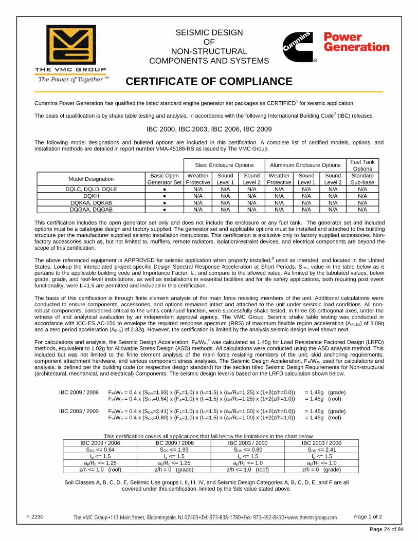
Cummins Power Generation has qualified the listed standard engine generator set packages as CERTIFIED1 for seismic application.
The basis of qualification is by shake table testing and analysis, in accordance with the following International Building Code2 (IBC) releases.
IBC 2000, IBC 2003, IBC 2006, IBC 2009
The following model designations and bulleted options are included in this certification. A complete list of certified models, options, andinstallation methods are detailed in report number VMA-45188-RS as issued by The VMC Group.
Fuel TankOptions
Model Designation Basic OpenGenerator Set
WeatherProtective
SoundLevel 1
SoundLevel 2
WeatherProtective
SoundLevel 1
SoundLevel 2
StandardSub-base
DQLC, DQLD, DQLE ● N/A N/A N/A N/A N/A N/A N/ADQKH ● N/A N/A N/A N/A N/A N/A N/A
DQKAA, DQKAB ● N/A N/A N/A N/A N/A N/A N/ADQGAA, DQGAB ● N/A N/A N/A N/A N/A N/A N/A
Steel Enclosure Options Aluminum Enclosure Options
This certification includes the open generator set only and does not include the enclosure or any fuel tank. The generator set and includedoptions must be a catalogue design and factory supplied. The generator set and applicable options must be installed and attached to the buildingstructure per the manufacturer supplied seismic installation instructions. This certification is exclusive only to factory supplied accessories. Non-factory accessories such as, but not limited to, mufflers, remote radiators, isolation/restraint devices, and electrical components are beyond thescope of this certification.
The above referenced equipment is APPROVED for seismic application when properly installed,3 used as intended, and located in the UnitedStates. Lookup the interpolated project specific Design Spectral Response Acceleration at Short Periods, SDS, value in the table below as itpertains to the applicable building code and Importance Factor, IP, and compare to the allowed value. As limited by the tabulated values, belowgrade, grade, and roof-level installations, as well as installations in essential facilities and for life safety applications, both requiring post eventfunctionality, were IP=1.5 are permitted and included in this certification.
The basis of this certification is through finite element analysis of the main force resisting members of the unit. Additional calculations wereconducted to ensure components, accessories, and options remained intact and attached to the unit under seismic load conditions. All non-robust components, considered critical to the unit’s continued function, were successfully shake tested, in three (3) orthogonal axes, under thewitness of and analytical evaluation by an independent approval agency, The VMC Group. Seismic shake table testing was conducted inaccordance with ICC-ES AC-156 to envelope the required response spectrum (RRS) of maximum flexible region acceleration (AFLEX) of 3.09gand a zero period acceleration (ARIG) of 2.32g. However, the certification is limited by the analysis seismic design level shown next.
For calculations and analysis, the Seismic Design Acceleration, FP/WP,4 was calculated as 1.45g for Load Resistance Factored Design (LRFD)methods, equivalent to 1.02g for Allowable Stress Design (ASD) methods. All calculations were conducted using the ASD analysis method. Thisincluded but was not limited to the finite element analysis of the main force resisting members of the unit, skid anchoring requirements,component attachment hardware, and various component stress analyses. The Seismic Design Acceleration, FP/WP, used for calculations andanalysis, is defined per the building code (or respective design standard) for the section titled Seismic Design Requirements for Non-structural(architectural, mechanical, and electrical) Components. The seismic design level is based on the LRFD calculation shown below.
IBC 2009 / 2006 FP/WP = 0.4 x (SDS=1.93) x (FA=1.0) x (IP=1.5) x (aP/RP=1.25) x (1+2(z/h=0.0)) = 1.45g (grade)FP/WP = 0.4 x (SDS=0.64) x (FA=1.0) x (IP=1.5) x (aP/RP=1.25) x (1+2(z/h=1.0)) = 1.45g (roof)
IBC 2003 / 2000 FP/WP = 0.4 x (SDS=2.41) x (FA=1.0) x (IP=1.5) x (aP/RP=1.00) x (1+2(z/h=0.0)) = 1.45g (grade)FP/WP = 0.4 x (SDS=0.80) x (FA=1.0) x (IP=1.5) x (aP/RP=1.00) x (1+2(z/h=1.0)) = 1.45g (roof)
This certification covers all applications that fall below the limitations in the chart below.IBC 2009 / 2006 IBC 2009 / 2006 IBC 2003 / 2000 IBC 2003 / 2000
SDS <= 0.64 SDS <= 1.93 SDS <= 0.80 SDS <= 2.41Ip <= 1.5 Ip <= 1.5 Ip <= 1.5 Ip <= 1.5
ap/Rp <= 1.25 ap/Rp <= 1.25 ap/Rp <= 1.0 ap/Rp <= 1.0z/h <= 1.0 (roof) z/h = 0 (grade) z/h <= 1.0 (roof) z/h = 0 (grade)
Soil Classes A, B, C, D, E, Seismic Use groups I, II, III, IV, and Seismic Design Categories A, B, C, D, E, and F are allcovered under this certification, limited by the Sds value stated above.
Page 24 of 84
ff028
Pencil
SEISMIC DESIGNOF
NON-STRUCTURALCOMPONENTS AND SYSTEMS
CERTIFICATE OF COMPLIANCE
F-2230 Page 2 of 2
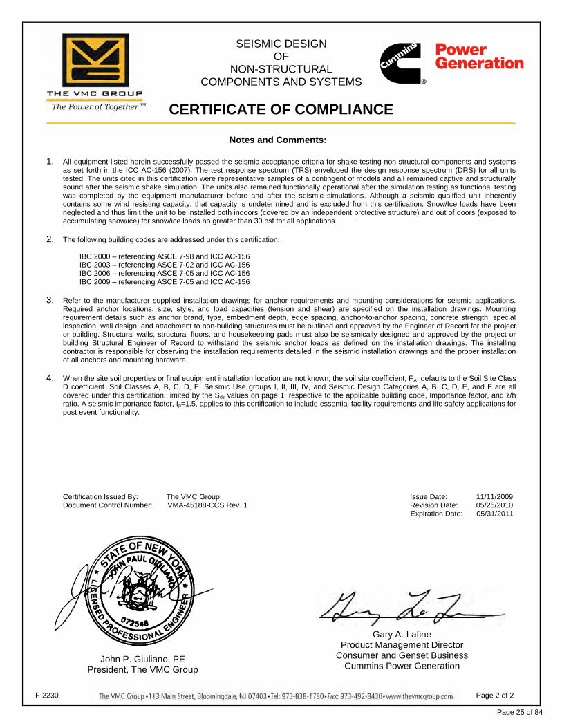
Notes and Comments:
1. All equipment listed herein successfully passed the seismic acceptance criteria for shake testing non-structural components and systemsas set forth in the ICC AC-156 (2007). The test response spectrum (TRS) enveloped the design response spectrum (DRS) for all unitstested. The units cited in this certification were representative samples of a contingent of models and all remained captive and structurallysound after the seismic shake simulation. The units also remained functionally operational after the simulation testing as functional testingwas completed by the equipment manufacturer before and after the seismic simulations. Although a seismic qualified unit inherentlycontains some wind resisting capacity, that capacity is undetermined and is excluded from this certification. Snow/Ice loads have beenneglected and thus limit the unit to be installed both indoors (covered by an independent protective structure) and out of doors (exposed toaccumulating snow/ice) for snow/ice loads no greater than 30 psf for all applications.
2. The following building codes are addressed under this certification:
IBC 2000 – referencing ASCE 7-98 and ICC AC-156IBC 2003 – referencing ASCE 7-02 and ICC AC-156IBC 2006 – referencing ASCE 7-05 and ICC AC-156IBC 2009 – referencing ASCE 7-05 and ICC AC-156
3. Refer to the manufacturer supplied installation drawings for anchor requirements and mounting considerations for seismic applications.Required anchor locations, size, style, and load capacities (tension and shear) are specified on the installation drawings. Mountingrequirement details such as anchor brand, type, embedment depth, edge spacing, anchor-to-anchor spacing, concrete strength, specialinspection, wall design, and attachment to non-building structures must be outlined and approved by the Engineer of Record for the projector building. Structural walls, structural floors, and housekeeping pads must also be seismically designed and approved by the project orbuilding Structural Engineer of Record to withstand the seismic anchor loads as defined on the installation drawings. The installingcontractor is responsible for observing the installation requirements detailed in the seismic installation drawings and the proper installationof all anchors and mounting hardware.
4. When the site soil properties or final equipment installation location are not known, the soil site coefficient, FA, defaults to the Soil Site ClassD coefficient. Soil Classes A, B, C, D, E, Seismic Use groups I, II, III, IV, and Seismic Design Categories A, B, C, D, E, and F are allcovered under this certification, limited by the Sds values on page 1, respective to the applicable building code, Importance factor, and z/hratio. A seismic importance factor, Ip=1.5, applies to this certification to include essential facility requirements and life safety applications forpost event functionality.
Certification Issued By: The VMC Group Issue Date: 11/11/2009Document Control Number: VMA-45188-CCS Rev. 1 Revision Date: 05/25/2010
Expiration Date: 05/31/2011
John P. Giuliano, PEPresident, The VMC Group
Gary A. LafineProduct Management Director
Consumer and Genset BusinessCummins Power Generation
Page 25 of 84
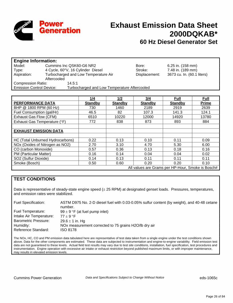
Exhaust Emission Data Sheet2000DQKAB*
60 Hz Diesel Generator Set
Engine Information: Model: Cummins Inc QSK60-G6 NR2 Bore: 6.25 in. (158 mm) Type: 4 Cycle, 60°V, 16 Cylinder Diesel Stroke: 7.48 in. (189 mm) Aspiration: Turbocharged and Low Temperature Air
Aftercooled Displacement: 3673 cu. In. (60.1 liters)
Compression Ratio: 14.5:1 Emission Control Device: Turbocharged and Low Temperature Aftercooled
1/4 1/2 3/4 Full Full PERFORMANCE DATA Standby Standby Standby Standby Prime BHP @ 1800 RPM (60 Hz) 730 1460 2189 2919 2639 Fuel Consumption (gal/Hr) 46.5 82 107.3 141.3 124.1 Exhaust Gas Flow (CFM) 6510 10220 12000 14920 13780 Exhaust Gas Temperature (°F) 772 838 873 893 884 EXHAUST EMISSION DATA HC (Total Unburned Hydrocarbons) 0.22 0.13 0.10 0.11 0.09 NOx (Oxides of Nitrogen as NO2) 2.70 3.10 4.70 5.30 6.00 CO (carbon Monoxide) 0.57 0.36 0.13 0.18 0.16 PM (Particular Matter) 0.16 0.14 0.04 0.04 0.02 SO2 (Sulfur Dioxide) 0.14 0.13 0.11 0.11 0.11 Smoke (Bosch) 0.50 0.60 0.20 0.20 0.10
All values are Grams per HP-Hour, Smoke is Bosch#
TEST CONDITIONS Data is representative of steady-state engine speed (± 25 RPM) at designated genset loads. Pressures, temperatures, and emission rates were stabilized. Fuel Specification: ASTM D975 No. 2-D diesel fuel with 0.03-0.05% sulfur content (by weight), and 40-48 cetane
number. Fuel Temperature: 99 ± 9 °F (at fuel pump inlet) Intake Air Temperature: 77 ± 9 °F Barometric Pressure: 29.6 ± 1 in. Hg Humidity: NOx measurement corrected to 75 grains H2O/lb dry air Reference Standard: ISO 8178 The NOx, HC, CO and PM emission data tabulated here are representative of test data taken from a single engine under the test conditions shown above. Data for the other components are estimated. These data are subjected to instrumentation and engine-to-engine variability. Field emission test data are not guaranteed to these levels. Actual field test results may vary due to test site conditions, installation, fuel specification, test procedures and instrumentation. Engine operation with excessive air intake or exhaust restriction beyond published maximum limits, or with improper maintenance, may results in elevated emission levels.
Cummins Power Generation Data and Specifications Subject to Change Without Notice eds-1065c
Page 26 of 84
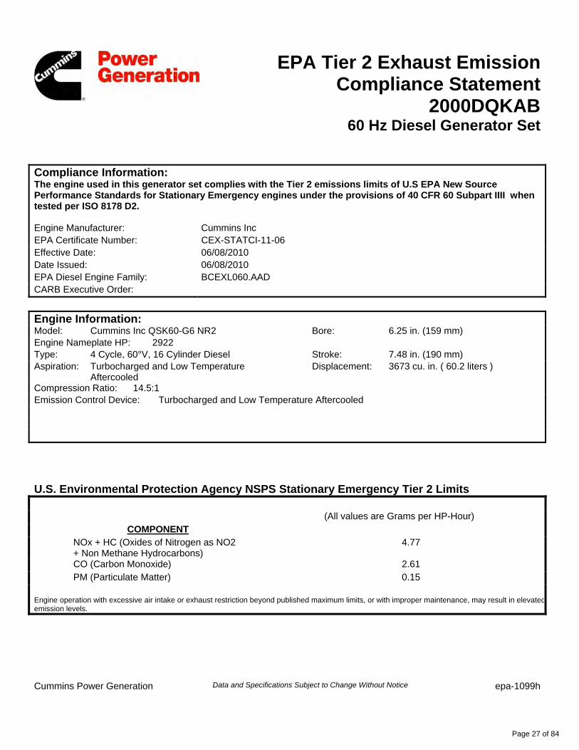
EPA Tier 2 Exhaust Emission Compliance Statement
2000DQKAB60 Hz Diesel Generator Set
Compliance Information: The engine used in this generator set complies with the Tier 2 emissions limits of U.S EPA New Source Performance Standards for Stationary Emergency engines under the provisions of 40 CFR 60 Subpart IIII when tested per ISO 8178 D2. Engine Manufacturer: Cummins Inc EPA Certificate Number: CEX-STATCI-11-06 Effective Date: 06/08/2010 Date Issued: 06/08/2010 EPA Diesel Engine Family: BCEXL060.AAD CARB Executive Order:
Engine Information: Model: Cummins Inc QSK60-G6 NR2 Bore: 6.25 in. (159 mm) Engine Nameplate HP: 2922 Type: 4 Cycle, 60°V, 16 Cylinder Diesel Stroke: 7.48 in. (190 mm) Aspiration: Turbocharged and Low Temperature
Aftercooled Displacement: 3673 cu. in. ( 60.2 liters )
Compression Ratio: 14.5:1 Emission Control Device: Turbocharged and Low Temperature Aftercooled
U.S. Environmental Protection Agency NSPS Stationary Emergency Tier 2 Limits (All values are Grams per HP-Hour)
COMPONENT
NOx + HC (Oxides of Nitrogen as NO2 + Non Methane Hydrocarbons)
4.77
CO (Carbon Monoxide) 2.61
PM (Particulate Matter) 0.15 Engine operation with excessive air intake or exhaust restriction beyond published maximum limits, or with improper maintenance, may result in elevatedemission levels.
Cummins Power Generation Data and Specifications Subject to Change Without Notice epa-1099h
Page 27 of 84
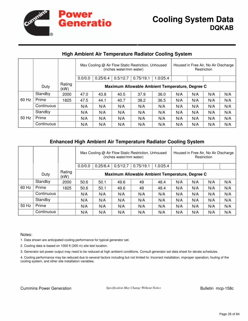
Cooling System Data
DQKAB
High Ambient Air Temperature Radiator Cooling System
Max Cooling @ Air Flow Static Restriction, Unhoused
(inches water/mm water)
Housed in Free Air, No Air Discharge Restriction
0.0/0.0 0.25/6.4 0.5/12.7 0.75/19.1 1.0/25.4
Duty
Rating (kW)
Maximum Allowable Ambient Temperature, Degree C
Standby 2000 47.0 43.8 40.5 37.9 36.0 N/A N/A N/A N/A
60 Hz Prime 1825 47.5 44.1 40.7 38.2 36.5 N/A N/A N/A N/A
Continuous N/A N/A N/A N/A N/A N/A N/A N/A N/A
Standby N/A N/A N/A N/A N/A N/A N/A N/A N/A
50 Hz Prime N/A N/A N/A N/A N/A N/A N/A N/A N/A
Continuous N/A N/A N/A N/A N/A N/A N/A N/A N/A
Enhanced High Ambient Air Temperature Radiator Cooling System
Max Cooling @ Air Flow Static Restriction, Unhoused
(inches water/mm water)
Housed in Free Air, No Air Discharge Restriction
0.0/0.0 0.25/6.4 0.5/12.7 0.75/19.1 1.0/25.4
Duty
Rating (kW)
Maximum Allowable Ambient Temperature, Degree C
Standby 2000 50.6 50.1 49.6 49 48.4 N/A N/A N/A N/A
60 Hz Prime 1825 50.6 50.1 49.6 49 48.4 N/A N/A N/A N/A
Continuous N/A N/A N/A N/A N/A N/A N/A N/A N/A
Standby N/A N/A N/A N/A N/A N/A N/A N/A N/A
50 Hz Prime N/A N/A N/A N/A N/A N/A N/A N/A N/A
Continuous N/A N/A N/A N/A N/A N/A N/A N/A N/A
Notes:
1. Data shown are anticipated cooling performance for typical generator set.
2. Cooling data is based on 1000 ft (305 m) site test location.
3. Generator set power output may need to be reduced at high ambient conditions. Consult generator set data sheet for derate schedules.
4. Cooling performance may be reduced due to several factors including but not limited to: Incorrect installation, improper operation, fouling of the cooling system, and other site installation variables.
Cummins Power Generation Specification May Change Without Notice Bulletin mcp-158c
Page 28 of 84
hf433
Stamp
ff028
Rectangle
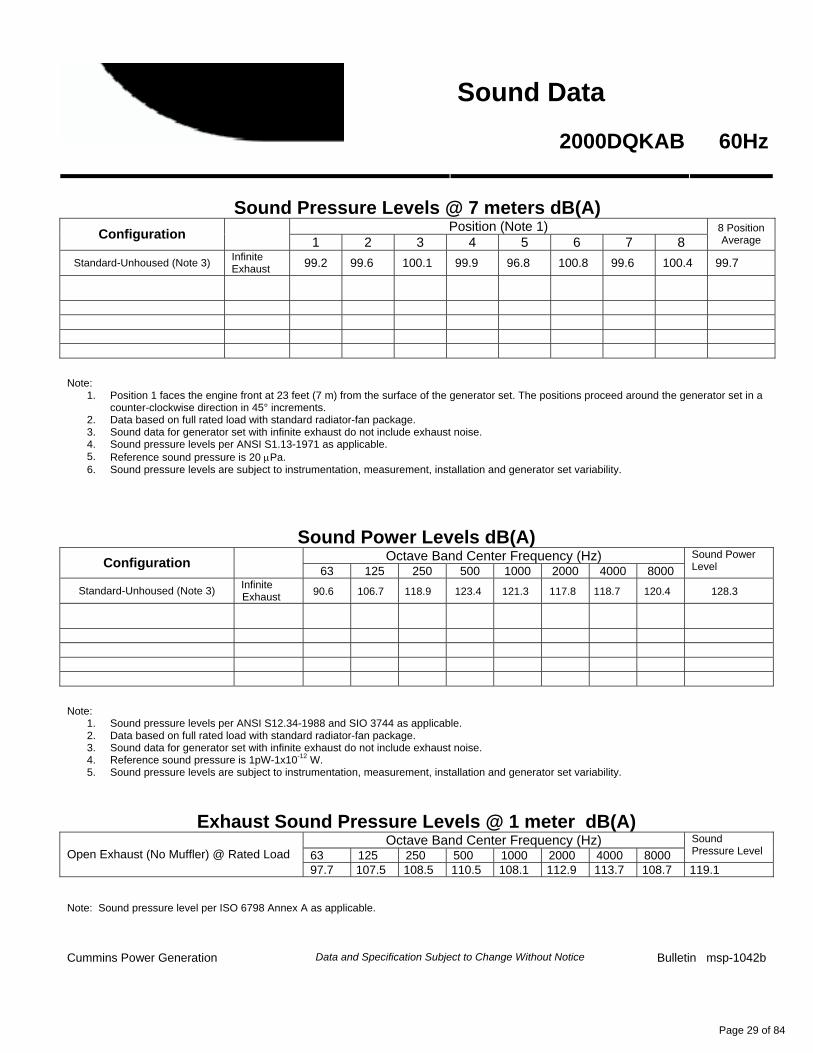
Sound Data
2000DQKAB 60Hz
Sound Pressure Levels @ 7 meters dB(A)
Position (Note 1) Configuration
1 2 3 4 5 6 7 8
8 Position Average
Standard-Unhoused (Note 3) Infinite Exhaust 99.2 99.6 100.1 99.9 96.8 100.8 99.6 100.4 99.7
Note:
1. Position 1 faces the engine front at 23 feet (7 m) from the surface of the generator set. The positions proceed around the generator set in a counter-clockwise direction in 45° increments.
2. Data based on full rated load with standard radiator-fan package. 3. Sound data for generator set with infinite exhaust do not include exhaust noise. 4. Sound pressure levels per ANSI S1.13-1971 as applicable. 5. Reference sound pressure is 20 µPa. 6. Sound pressure levels are subject to instrumentation, measurement, installation and generator set variability.
Sound Power Levels dB(A) Octave Band Center Frequency (Hz)
Configuration
63 125 250 500 1000 2000 4000 8000 Sound Power Level
Standard-Unhoused (Note 3) Infinite Exhaust 90.6 106.7 118.9 123.4 121.3 117.8 118.7 120.4 128.3
Note:
1. Sound pressure levels per ANSI S12.34-1988 and SIO 3744 as applicable. 2. Data based on full rated load with standard radiator-fan package. 3. Sound data for generator set with infinite exhaust do not include exhaust noise. 4. Reference sound pressure is 1pW-1x10-12 W. 5. Sound pressure levels are subject to instrumentation, measurement, installation and generator set variability.
Exhaust Sound Pressure Levels @ 1 meter dB(A) Octave Band Center Frequency (Hz)
63 125 250 500 1000 2000 4000 8000 Sound Pressure Level Open Exhaust (No Muffler) @ Rated Load
97.7 107.5 108.5 110.5 108.1 112.9 113.7 108.7 119.1 Note: Sound pressure level per ISO 6798 Annex A as applicable. Cummins Power Generation Data and Specification Subject to Change Without Notice Bulletin msp-1042b
Page 29 of 84
hf433
Stamp
ff028
Rectangle
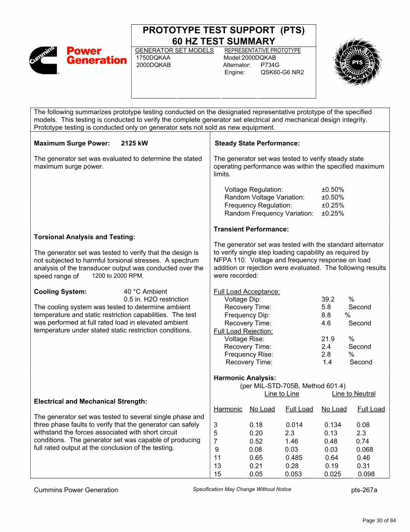
PROTOTYPE TEST SUPPORT (PTS)
60 HZ TEST SUMMARYGENERATOR SET MODELS REPRESENTATIVE PROTOTYPE1750DQKAA Model:2000DQKAB2000DQKAB Alternator: P734G
Engine: QSK60-G6 NR2
The following summarizes prototype testing conducted on the designated representative prototype of the specified models. This testing is conducted to verify the complete generator set electrical and mechanical design integrity. Prototype testing is conducted only on generator sets not sold as new equipment.
Maximum Surge Power: 2125 kW Steady State Performance:
The generator set was evaluated to determine the statedmaximum surge power.
The generator set was tested to verify steady state operating performance was within the specified maximum limits.
Voltage Regulation: ±0.50%Random Voltage Variation: ±0.50%
Frequency Regulation: ±0.25% Random Frequency Variation: ±0.25%
Transient Performance: Torsional Analysis and Testing:
The generator set was tested to verify that the design is not subjected to harmful torsional stresses. A spectrum analysis of the transducer output was conducted over the
speed range of 1200 to 2000 RPM.
The generator set was tested with the standard alternator to verify single step loading capability as required by NFPA 110. Voltage and frequency response on load addition or rejection were evaluated. The following results were recorded:
Cooling System: 40 °C Ambient Full Load Acceptance:0.5 in. H2O restriction Voltage Dip: 39.2 %
Recovery Time: 5.8 Second
Frequency Dip: 8.8 %
Recovery Time: 4.6 Second
The cooling system was tested to determine ambient temperature and static restriction capabilities. The test was performed at full rated load in elevated ambient temperature under stated static restriction conditions. Full Load Rejection:
Voltage Rise: 21.9 %Recovery Time: 2.4 Second Frequency Rise: 2.8 %Recovery Time: 1.4 Second
Harmonic Analysis:
(per MIL-STD-705B, Method 601.4) Line to Line Line to NeutralElectrical and Mechanical Strength: Harmonic No Load Full Load No Load Full Load
3 0.18 0.014 0.134 0.085 0.20 2.3 0.13 2.37 0.52 1.46 0.48 0.749 0.08 0.03 0.03 0.06811 0.65 0.485 0.64 0.4613 0.21 0.28 0.19 0.31
The generator set was tested to several single phase and three phase faults to verify that the generator can safely withstand the forces associated with short circuit conditions. The generator set was capable of producing full rated output at the conclusion of the testing.
15 0.05 0.053 0.025 0.098
Cummins Power Generation Specification May Change Without Notice pts-267a
Page 30 of 84
ff028
Rectangle
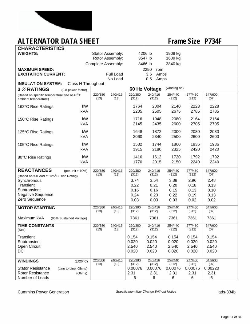
ALTERNATOR DATA SHEET Frame Size P734F CHARACTERISTICS
WEIGHTS: Stator Assembly: 4206 lb 1908 kg Rotor Assembly: 3547 lb 1609 kg Complete Assembly: 8466 lb 3840 kg MAXIMUM SPEED: 2250 rpm
Full Load 3.6 Amps EXCITATION CURRENT: No Load 0.5 Amps
INSULATION SYSTEM: Class H Throughout 60 Hz Voltage (winding no) 3 ∅ RATINGS (0.8 power factor)
(Based on specific temperature rise at 40°C ambient temperature)
220/380 (13)
240/416 (13)
220/380 (312)
240/416 (312)
254/440 (312)
277/480 (312)
347/600 (07)
163°C Rise Ratings kW 1764 2004 2140 2228 2228 kVA 2205 2505 2675 2785 2785
150°C Rise Ratings kW 1716 1948 2080 2164 2164 kVA 2145 2435 2600 2705 2705
125°C Rise Ratings kW 1648 1872 2000 2080 2080 kVA 2060 2340 2500 2600 2600
105°C Rise Ratings kW 1532 1744 1860 1936 1936 kVA 1915 2180 2325 2420 2420
80°C Rise Ratings kW 1416 1612 1720 1792 1792 kVA 1770 2015 2150 2240 2240
220/380 (13)
240/416 (13)
220/380 (312)
240/416 (312)
254/440 (312)
277/480 (312)
347/600 (07)
3.74 3.54 3.38 2.96 2.48 0.22 0.21 0.20 0.18 0.13 0.16 0.16 0.15 0.13 0.10 0.24 0.23 0.22 0.19 0.13 0.03 0.03 0.03 0.02 0.02
REACTANCES (per unit ± 10%) (Based on full load at 125°C Rise Rating) Synchronous Transient Subtransient Negative Sequence Zero Sequence
MOTOR STARTING 220/380 (13)
240/416 (13)
220/380 (312)
240/416 (312)
254/440 (312)
277/480 (312)
347/600 (07)
Maximum kVA (90% Sustained Voltage) 7361 7361 7361 7361 7361
TIME CONSTANTS (Sec)
220/380 (13)
240/416 (13)
220/380 (312)
240/416 (312)
254/440 (312)
277/480 (312)
347/600 (07)
Transient 0.154 0.154 0.154 0.154 0.154 Subtransient 0.020 0.020 0.020 0.020 0.020 Open Circuit 2.540 2.540 2.540 2.540 2.540 DC 0.020 0.020 0.020 0.020 0.020 WINDINGS (@20°C) 220/380
(13) 240/416
(13) 220/380
(312) 240/416
(312) 254/440
(312) 277/480
(312) 347/600
(07)
Stator Resistance (Line to Line, Ohms) 0.00076 0.00076 0.00076 0.00076 0.00220 Rotor Resistance (Ohms) 2.31 2.31 2.31 2.31 2.31 Number of Leads 6 6 6 6 6
Cummins Power Generation Specification May Change Without Notice ads-334b
Page 31 of 84
hf433
Stamp
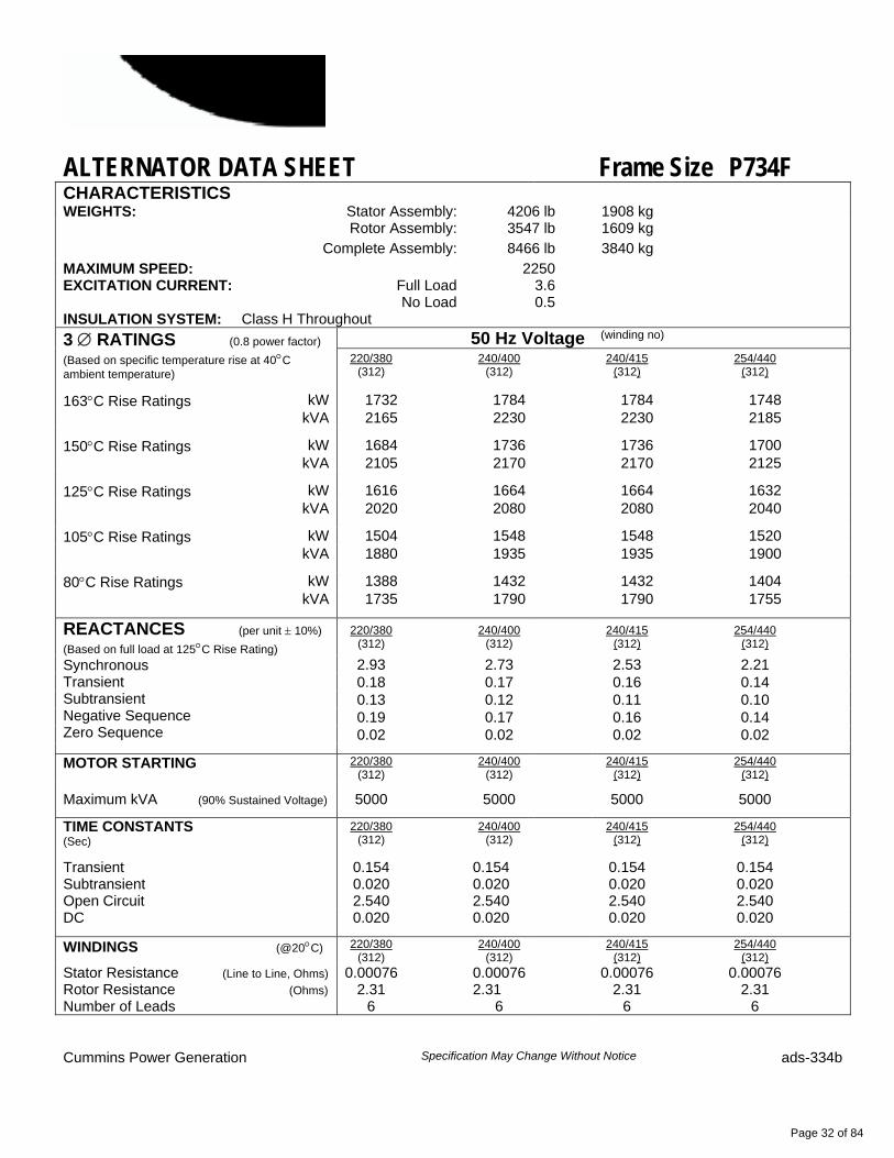
ALTERNATOR DATA SHEET Frame Size P734F CHARACTERISTICS
WEIGHTS: Stator Assembly: 4206 lb 1908 kg Rotor Assembly: 3547 lb 1609 kg Complete Assembly: 8466 lb 3840 kg MAXIMUM SPEED: 2250
Full Load 3.6 EXCITATION CURRENT: No Load 0.5
INSULATION SYSTEM: Class H Throughout 50 Hz Voltage (winding no) 3 ∅ RATINGS (0.8 power factor)
(Based on specific temperature rise at 40°C ambient temperature)
220/380 (312) 240/400
(312) 240/415 (312) 254/440
(312)
163°C Rise Ratings kW 1732 1784 1784 1748 kVA 2165 2230 2230 2185
150°C Rise Ratings kW 1684 1736 1736 1700 kVA 2105 2170 2170 2125
125°C Rise Ratings kW 1616 1664 1664 1632 kVA 2020 2080 2080 2040
105°C Rise Ratings kW 1504 1548 1548 1520 kVA 1880 1935 1935 1900
80°C Rise Ratings kW 1388 1432 1432 1404 kVA 1735 1790 1790 1755
220/380 (312) 240/400
(312) 240/415 (312) 254/440
(312)
2.93 2.73 2.53 2.21 0.18 0.17 0.16 0.14 0.13 0.12 0.11 0.10 0.19 0.17 0.16 0.14 0.02 0.02 0.02 0.02
REACTANCES (per unit ± 10%) (Based on full load at 125°C Rise Rating) Synchronous Transient Subtransient Negative Sequence Zero Sequence
MOTOR STARTING 220/380 (312) 240/400
(312) 240/415 (312) 254/440
(312)
Maximum kVA (90% Sustained Voltage) 5000 5000 5000 5000
TIME CONSTANTS (Sec)
220/380 (312) 240/400
(312) 240/415 (312) 254/440
(312)
Transient 0.154 0.154 0.154 0.154 Subtransient 0.020 0.020 0.020 0.020 Open Circuit 2.540 2.540 2.540 2.540 DC 0.020 0.020 0.020 0.020
WINDINGS (@20°C) 220/380 (312) 240/400
(312) 240/415 (312) 254/440
(312)
Stator Resistance (Line to Line, Ohms) 0.00076 0.00076 0.00076 0.00076 Rotor Resistance (Ohms) 2.31 2.31 2.31 2.31 Number of Leads 6 6 6 6
Cummins Power Generation Specification May Change Without Notice ads-334b
Page 32 of 84
hf433
Stamp
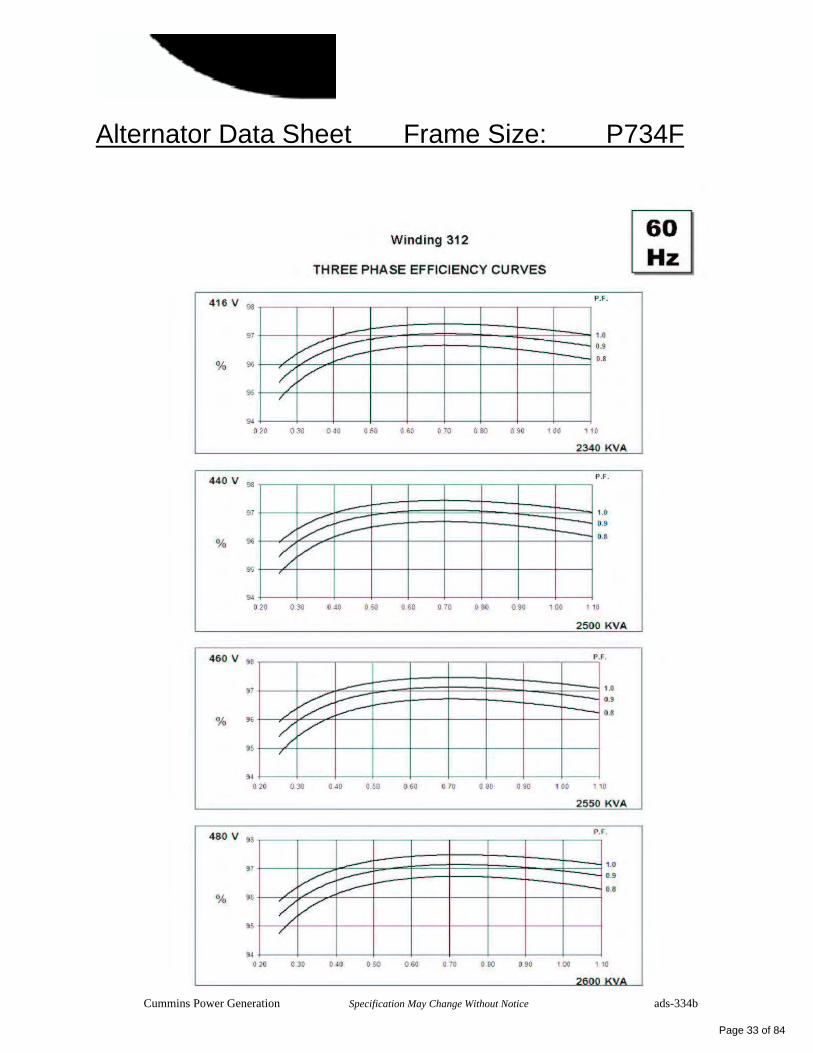
Alternator Data Sheet Frame Size: P734F
Cummins Power Generation Specification May Change Without Notice ads-334b
Page 33 of 84
hf433
Stamp
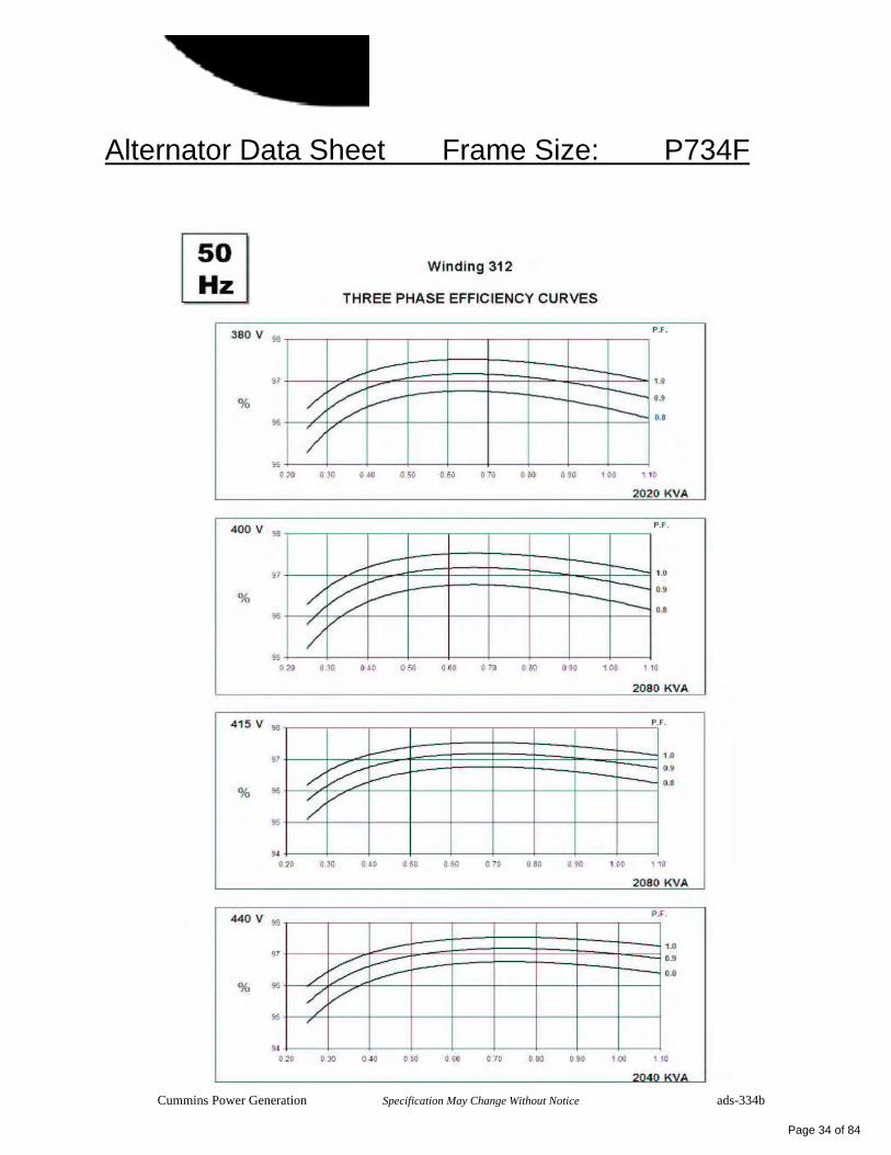
Alternator Data Sheet Frame Size: P734F
Cummins Power Generation Specification May Change Without Notice ads-334b
Page 34 of 84
hf433
Stamp

Alternator Data Sheet Frame Size: P734F
Cummins Power Generation Specification May Change Without Notice ads-334b
Page 35 of 84
hf433
Stamp
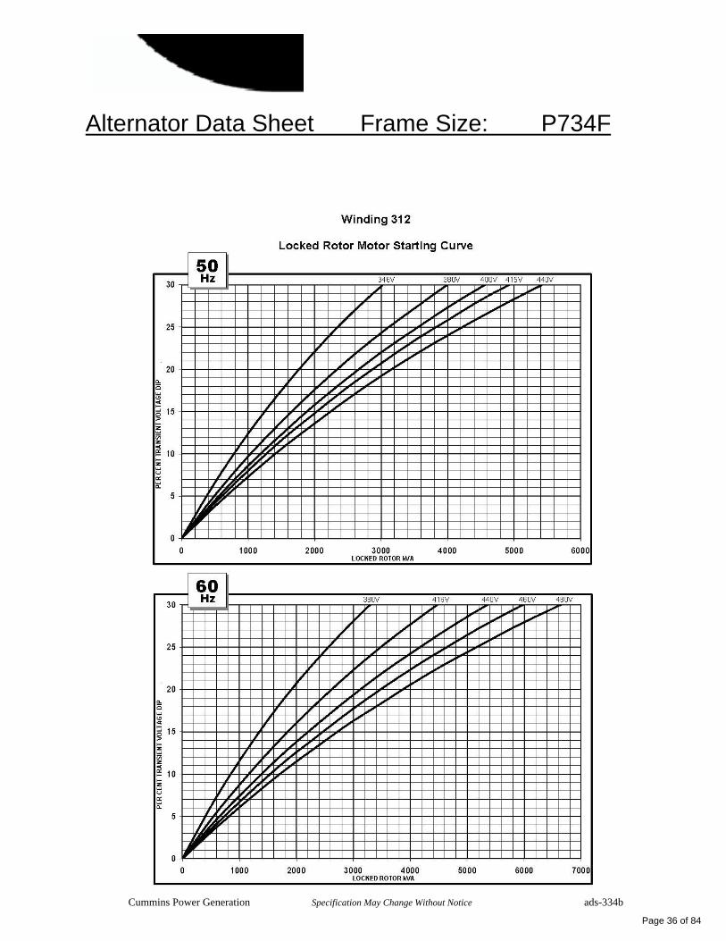
Alternator Data Sheet Frame Size: P734F
Cummins Power Generation Specification May Change Without Notice ads-334b
Page 36 of 84
hf433
Stamp
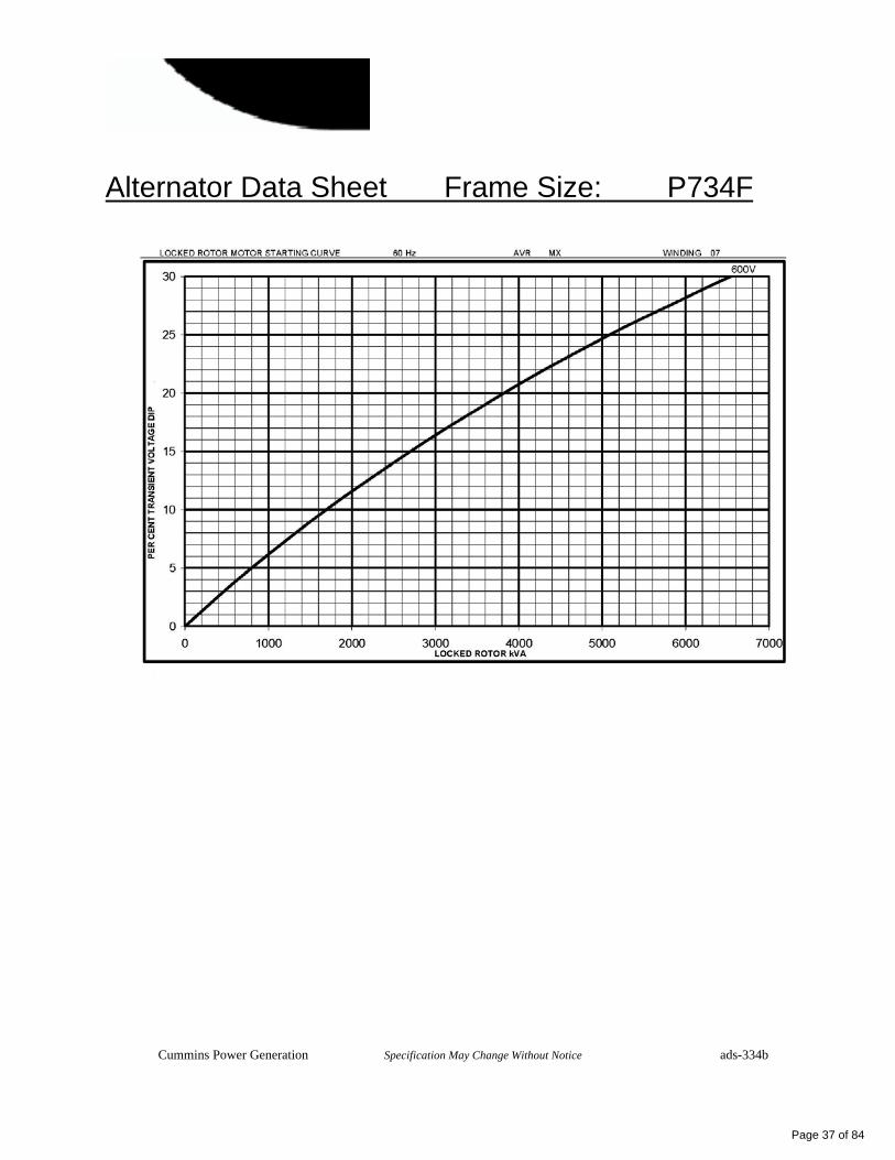
Alternator Data Sheet Frame Size: P734F
Cummins Power Generation Specification May Change Without Notice ads-334b
Page 37 of 84
hf433
Stamp

Alternator Data Sheet Frame Size: P734F
Cummins Power Generation Specification May Change Without Notice ads-334b
Page 38 of 84
hf433
Stamp

Alternator Data Sheet Frame Size: P734F
Cummins Power Generation Specification May Change Without Notice ads-334b
Page 39 of 84
hf433
Stamp

Our energy working for you.™
Final standards for stationary and nonroaddiesel generator sets
On July 11, 2006, the US EPA fi nalized its proposalto regulate emissions from stationary dieselcompression-ignition engines. Called the “NewSource Performance Standards,” the EPA rulerequires emissions from stationary diesel-poweredgenerator sets to be harmonized with nonroad(mobile) applications starting from January 1, 2007.
As a result of the rule:
> Generators with engine ratings of 10-99 hp must comply with Tier 2 regulations;
> Generators with engine ratings of 100-751 hp must comply with Tier 3 regulations;
> Generators with engine ratings of 752-3000 hp must comply with Tier 2 regulations;
> Engines that are not certifi ed to 2007 nonroad standards must be installed by the end-user by January 1, 2009.
Key exceptions are:
> Stationary engines over 3000 hp will remain at Tier 1 until their Tier 4 requirements become effective in 2011.
> Beginning in 2011 at Tier 4, emergency stationary diesel generators will not have to advance to standards that require aftertreatment.
U.S. EPA emissions regulations for on-site power generation
Proposed regulations for spark-ignited gasengines
On June 12, 2006, the EPA proposed new rules toregulate emissions from stationary spark-ignited gasengines. The fi rst regulation will become effectiveJuly 1, 2007, when emissions levels for stationarynon-emergency engines (typically used in peaking and landfi ll gas) and engines below 25 hp will be regulated. Spark-ignited gas engines above 25 hp used in stationary emergency applications will require EPA certifi cation effective January 1, 2009.
Cummins Power Generation intends to offer EPA-certifi ed gas products to meet the EPA stationaryemergency requirements for spark-ignited gas. Please consult your Cummins Power Generation dealer or visit www.cumminspower.com for a list of our EPA-compliant gas generator sets.
Award-winning diesel technology
Frost & Sullivan named Cummins Power Generation the recipient of the 2006 North American Diesel Engine Technology Leadership of the Year Award. The award recognizes Cummins Power Generation’s advancements and market leadership in emissions technology.
Our energy working for you.™
www.cumminspower.com
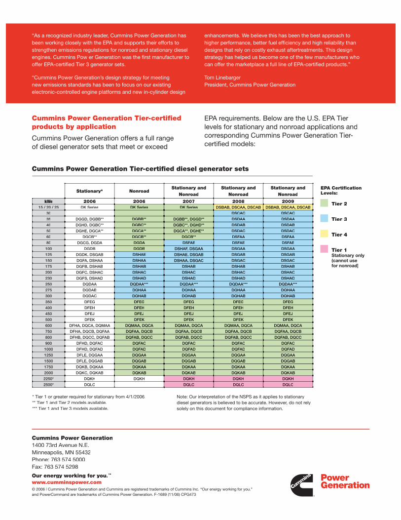
Cummins Power Generation1400 73rd Avenue N.E.Minneapolis, MN 55432Phone: 763 574 5000Fax: 763 574 5298
Our energy working for you.™
www.cumminspower.com© 2006 | Cummins Power Generation and Cummins are registered trademarks of Cummins Inc. “Our energy working for you.” and PowerCommand are trademarks of Cummins Power Generation. F-1689 (11/06) CPG473
Cummins Power Generation Tier-certifi edproducts by application
Cummins Power Generation offers a full rangeof diesel generator sets that meet or exceed
EPA requirements. Below are the U.S. EPA Tierlevels for stationary and nonroad applications andcorresponding Cummins Power Generation Tier-certifi ed models:
Stationary* NonroadStationary and
NonroadStationary and
NonroadStationary and
Nonroad
kWe 2006 2006 2007 2008 200915 / 20 / 25 DK Series DK Series DK Series DSBAB, DSCAA, DSCAB DSBAB, DSCAA, DSCAB
30 DSCAC DSCAC
35 DGGD, DGBB** DGBB** DGBB**, DGGD** DSDAA DSDAA
40 DGHD, DGBC** DGBC** DGBC**, DGHD** DSDAB DSDAB
50 DGHE, DGCA** DGCA** DGCA**, DGHE** DSDAC DSDAC
60 DGCB** DGCB** DGCB** DSFAA DSFAA
80 DGCG, DGDA DGDA DSFAE DSFAE DSFAE
100 DGDB DGDB DSHAF, DSGAA DSGAA DSGAA
125 DGDK, DSGAB DSHAE DSHAE, DSGAB DSGAB DSGAB
150 DGFA, DSHAA DSHAA DSHAA, DSGAC DSGAC DSGAC
175 DGFB, DSHAB DSHAB DSHAB DSHAB DSHAB
200 DGFC, DSHAC DSHAC DSHAC DSHAC DSHAC
230 DGFS, DSHAD DSHAD DSHAD DSHAD DSHAD
250 DQDAA DQDAA*** DQDAA*** DQDAA*** DQDAA***
275 DQDAB DQHAA DQHAA DQHAA DQHAA
300 DQDAC DQHAB DQHAB DQHAB DQHAB
350 DFEG DFEG DFEG DFEG DFEG
400 DFEH DFEH DFEH DFEH DFEH
450 DFEJ DFEJ DFEJ DFEJ DFEJ
500 DFEK DFEK DFEK DFEK DFEK
600 DFHA, DQCA, DQMAA DQMAA, DQCA DQMAA, DQCA DQMAA, DQCA DQMAA, DQCA
750 DFHA, DQCB, DQFAA DQFAA, DQCB DQFAA, DQCB DQFAA, DQCB DQFAA, DQCB
800 DFHB, DQCC, DQFAB DQFAB, DQCC DQFAB, DQCC DQFAB, DQCC DQFAB, DQCC
900 DFHD, DQFAC DQFAC DQFAC DQFAC DQFAC
1000 DFHD, DQFAD DQFAD DQFAD DQFAD DQFAD
1250 DFLE, DQGAA DQGAA DQGAA DQGAA DQGAA
1500 DFLE, DQGAB DQGAB DQGAB DQGAB DQGAB
1750 DQKB, DQKAA DQKAA DQKAA DQKAA DQKAA
2000 DQKC, DQKAB DQKAB DQKAB DQKAB DQKAB
2250* DQKH DQKH DQKH DQKH DQKH
2500* DQLC DQLC DQLC DQLC
* Tier 1 or greater required for stationary from 4/1/2006.** Tier 1 and Tier 2 models available.*** Tier 1 and Tier 3 models available.
Note: Our interpretation of the NSPS as it applies to stationary diesel generators is believed to be accurate. However, do not rely solely on this document for compliance information.
Cummins Power Generation Tier-certifi ed diesel generator sets
Tier 2
Tier 3
Tier 4
Tier 1Stationary only (cannot use for nonroad)
EPA Certifi cation Levels:
“As a recognized industry leader, Cummins Power Generation hasbeen working closely with the EPA and supports their efforts tostrengthen emissions regulations for nonroad and stationary dieselengines. Cummins Pow er Generation was the fi rst manufacturer tooffer EPA-certifi ed Tier 3 generator sets.
“Cummins Power Generation’s design strategy for meetingnew emissions standards has been to focus on our existingelectronic-controlled engine platforms and new in-cylinder design
enhancements. We believe this has been the best approach tohigher performance, better fuel effi ciency and high reliability thandesigns that rely on costly exhaust aftertreatments. This designstrategy has helped us become one of the few manufacturers whocan offer the marketplace a full line of EPA-certifi ed products.”
Tom LinebargerPresident, Cummins Power Generation
©2008|Cummins Power Generation Inc.|All rights reserved|Specifications subject to change without notice|Cummins Power Generation and Cummins are registered trademarks of Cummins Inc. “Our energy working for you.” is a trademark of Cummins Power Generation. S-1470d (5/08) Page 1 of 2
Four-stage battery charger 15 amp @ 12 volt 12 amp @ 24 volt
Description Features
Cummins Power Generation fully automatic battery chargers - using switched mode power electronics - are constant voltage/constant current chargers incorporating a 4-stage charging algorithm. Designed for use in applications where battery life and reliability are important; these chargers, complete with built-in equalize charge capability, are ideal for stationary or portable starting battery charging service.
To achieve optimum battery life, a 4-stage charging cycle is implemented. The four charging stages are trickle, bulk, absorption and float. The trickle stage safely charges overly discharged batteries. It protects a damaged or shorted battery from excessive current. During bulk charge a constant current is applied to quickly restore the maximum battery charge level in the shortest amount of time. The absorption stage applies a constant voltage to the battery to bring the battery to 100% capacity. The float stage tailors the constant voltage output to maintain the battery at full capacity while serving DC operated loads.
An optional temperature sensor may be used to adjust charging rate based on internal battery temperature in the absorption and float stages. Use of a battery temperature sensor helps to increase battery life by preventing over or under charging of the battery. The battery temperature sensor also protects the battery from overheating. Temperature compensation is recommended in all applications, but is particularly valuable for generator sets in outdoor applications.
Battery chargers are field-configurable for charging either 12 or 24 VDC battery systems and for operation at 50 or 60 Hz. Output voltage and battery type selection is done through the alphanumeric display.
Protection - All models include a 20 amp DC output breaker. Re-settable breakers are used for input voltages 240 VAC and lower. For over 240 VAC branch circuit rated fuses are used.
Easy installation - Clearly marked terminal blocks and panel knockouts provide convenient connections of input and output leads.
User display - Output voltage and current, fault information and configuration options are indicated on the alphanumeric display.
Monitoring - An LED indicates the condition of the charger. Green indicates normal charging operation, amber indicates equalizing and red indicates a fault condition.
Adjustable float voltage – Float voltage can be set through the alpha-numeric display for optimum battery performance and life.
Temperature compensation - An optional external sensor is available for temperature compensated battery charging.
Faults - The charger senses and annunciates the following fault conditions: Input overvoltage, input undervoltage, AC power loss, battery overvoltage, battery undervoltage, charger circuitry over temperature, battery over temperature, unrecoverable battery and overload/overcurrent. Includes 30 volt/2 amp isolated contact for common alarm.
Parallel redundant operation - Chargers can be operated in parallel for redundant reliability or additional charging capacity.
Vibration resistant design - complies with UL 991 vibration resistance requirements.
UL 1236 (BBHH) Listing - for use with lead acid batteries in generator set installations. Also suitable for use with NiCad, gel and AGM batteries.
Page 40 of 84
ff028
Rectangle
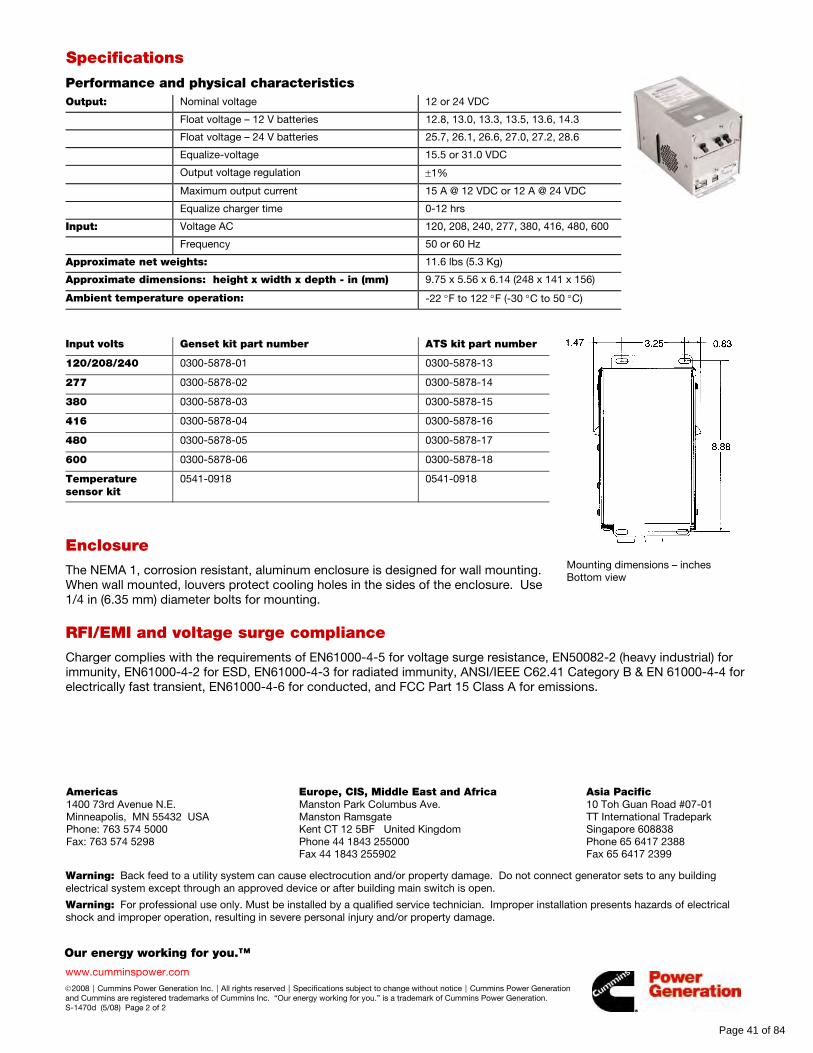
Our energy working for you.™
www.cumminspower.com
©2008|Cummins Power Generation Inc.|All rights reserved|Specifications subject to change without notice|Cummins Power Generation and Cummins are registered trademarks of Cummins Inc. “Our energy working for you.” is a trademark of Cummins Power Generation. S-1470d (5/08) Page 2 of 2
Specifications
Performance and physical characteristics Output: Nominal voltage 12 or 24 VDC
Float voltage – 12 V batteries 12.8, 13.0, 13.3, 13.5, 13.6, 14.3
Float voltage – 24 V batteries 25.7, 26.1, 26.6, 27.0, 27.2, 28.6
Equalize-voltage 15.5 or 31.0 VDC
Output voltage regulation ±1%
Maximum output current 15 A @ 12 VDC or 12 A @ 24 VDC
Equalize charger time 0-12 hrs
Input: Voltage AC 120, 208, 240, 277, 380, 416, 480, 600
Frequency 50 or 60 Hz
Approximate net weights: 11.6 lbs (5.3 Kg)
Approximate dimensions: height x width x depth - in (mm) 9.75 x 5.56 x 6.14 (248 x 141 x 156)
Ambient temperature operation: -22 °F to 122 °F (-30 °C to 50 °C)
Input volts Genset kit part number ATS kit part number
120/208/240 0300-5878-01 0300-5878-13
277 0300-5878-02 0300-5878-14
380 0300-5878-03 0300-5878-15
416 0300-5878-04 0300-5878-16
480 0300-5878-05 0300-5878-17
600 0300-5878-06 0300-5878-18
Temperature sensor kit
0541-0918 0541-0918
Enclosure The NEMA 1, corrosion resistant, aluminum enclosure is designed for wall mounting. When wall mounted, louvers protect cooling holes in the sides of the enclosure. Use 1/4 in (6.35 mm) diameter bolts for mounting.
Mounting dimensions – inches Bottom view
RFI/EMI and voltage surge compliance Charger complies with the requirements of EN61000-4-5 for voltage surge resistance, EN50082-2 (heavy industrial) for immunity, EN61000-4-2 for ESD, EN61000-4-3 for radiated immunity, ANSI/IEEE C62.41 Category B & EN 61000-4-4 for electrically fast transient, EN61000-4-6 for conducted, and FCC Part 15 Class A for emissions.
Americas 1400 73rd Avenue N.E. Minneapolis, MN 55432 USA Phone: 763 574 5000 Fax: 763 574 5298
Europe, CIS, Middle East and Africa Manston Park Columbus Ave. Manston Ramsgate Kent CT 12 5BF United Kingdom Phone 44 1843 255000 Fax 44 1843 255902
Asia Pacific 10 Toh Guan Road #07-01 TT International Tradepark Singapore 608838 Phone 65 6417 2388 Fax 65 6417 2399
Warning: Back feed to a utility system can cause electrocution and/or property damage. Do not connect generator sets to any building electrical system except through an approved device or after building main switch is open.
Warning: For professional use only. Must be installed by a qualified service technician. Improper installation presents hazards of electrical shock and improper operation, resulting in severe personal injury and/or property damage.
Page 41 of 84
ff028
Rectangle
©2007|Cummins Power Generation Inc.|All rights reserved|Specifications subject to change without notice|Cummins Power Generation and Cummins are registered trademarks of Cummins Inc. PowerCommand and “Our energy working for you.” are trademarks of Cummins Power Generation. Other company, product, or service names may be trademarks or service marks of others. S-1343e (9/07)
PowerCommand® Remote Annunciator Panel (LonWorks System annunciator)
Description Features
The PowerCommand® Network Annunciator is a network component that provides remote system status indication for emergency and other power systems in compliance to the requirements of NFPA 110. The network annunciator may also be used for remote indication of any condition that is monitored by a PowerCommand Network.
The Network Annunciator reduces installation costs and improves design flexibility by use of a PowerCommand Network to transmit all the genset and transfer switch system signals rather than using relay contacts for this purpose.
Control power for PowerCommand Network products is usually derived from the genset starting batteries. The control functions over a voltage range from 8 VDC to 35 VDC.
• Visual indication of 20 network conditions and network status.
• Audible indication of any network condition - Annunciator also includes pushbutton switch to silence the audible alarm. Alarm horn sound level is approximately 90 dB(A) at 30 cm.
• Standard NFPA 110 label, field configurable for other alarm and status conditions.
• Configurable for compliance to NFPA 99 requirements.
• Sealed membrane panel design provides environmental protection for internal components and is easy to clean.
• Warranty - PowerCommand Controls are supported by a worldwide network of independent distributors who provide parts, service and warranty support.
• UL Listed and labeled; CSA certified; CE marked.
• Wall mount NEMA 1 enclosure or flush mount configurations available.
Page 42 of 84
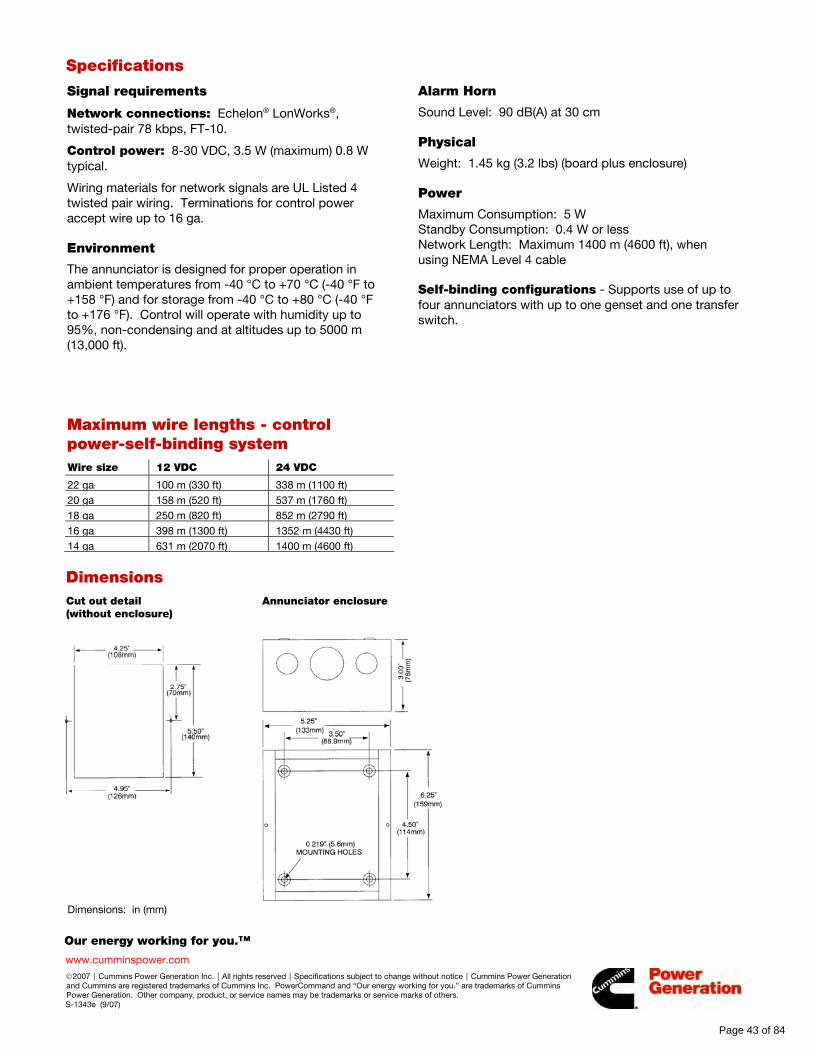
Our energy working for you.™
www.cumminspower.com
©2007|Cummins Power Generation Inc.|All rights reserved|Specifications subject to change without notice|Cummins Power Generation and Cummins are registered trademarks of Cummins Inc. PowerCommand and “Our energy working for you.” are trademarks of Cummins Power Generation. Other company, product, or service names may be trademarks or service marks of others. S-1343e (9/07)
Specifications
Signal requirements
Network connections: Echelon® LonWorks®, twisted-pair 78 kbps, FT-10.
Control power: 8-30 VDC, 3.5 W (maximum) 0.8 W typical.
Wiring materials for network signals are UL Listed 4 twisted pair wiring. Terminations for control power accept wire up to 16 ga.
Environment
The annunciator is designed for proper operation in ambient temperatures from -40 °C to +70 °C (-40 °F to +158 °F) and for storage from -40 °C to +80 °C (-40 °F to +176 °F). Control will operate with humidity up to 95%, non-condensing and at altitudes up to 5000 m (13,000 ft).
Maximum wire lengths - control power-self-binding system
Wire size 12 VDC 24 VDC
22 ga 100 m (330 ft) 338 m (1100 ft)
20 ga 158 m (520 ft) 537 m (1760 ft)
18 ga 250 m (820 ft) 852 m (2790 ft)
16 ga 398 m (1300 ft) 1352 m (4430 ft)
14 ga 631 m (2070 ft) 1400 m (4600 ft)
Alarm Horn
Sound Level: 90 dB(A) at 30 cm
Physical
Weight: 1.45 kg (3.2 lbs) (board plus enclosure)
Power
Maximum Consumption: 5 W Standby Consumption: 0.4 W or less Network Length: Maximum 1400 m (4600 ft), when using NEMA Level 4 cable
Self-binding configurations - Supports use of up to four annunciators with up to one genset and one transfer switch.
Dimensions
Cut out detail Annunciator enclosure (without enclosure)
Dimensions: in (mm)
Page 43 of 84
Our energy working for you.™
www.cumminspower.com
©2007|Cummins Power Generation Inc.|All rights reserved|Specifications subject to change without notice|Cummins Power Generation and Cummins are registered trademarks of Cummins Inc. PowerCommand and “Our energy working for you.” are trademarks of Cummins Power Generation. Other company, product, or service names may be trademarks or service marks of others. S-1343e (9/07)
Label configurations & standard bindings
NFPA 110 genset alarm and status annunciator
The following conditions are provided as standard on the annunciator: • High battery voltage (A) • Pre-high coolant temperature (A) • Battery charger malfunction (A) • Low battery voltage (A) • High coolant temperature (R) • Low fuel (A) • Genset running (G) • Low engine temperature (A) • Low coolant level (R) • Genset supplying load (G) • Overspeed (R) • Spare (4) (G) • Pre-low oil pressure (A) • Fail to start (overcrank) (R) • Common alarm • Low oil pressure (R) • Not in auto (R) (A) = Amber; (R) = Red; (G) = Green
Extended genset alarm and status annunciator
The following conditions are provided as standard on the annunciator: • Check genset (R) • Over current (R) • Load demand (G) • Ground fault (A) • Short circuit (R) • Genset CB tripped (R) • High AC voltage (R) • Reverse KW (R) • Utility CB tripped (R) • Low AC voltage (R) • Reverse kVAR (R) • Emergency stop (R) • Under frequency (R) • Fail to sync (A) • Spare (4) (G) • Overload (R) • Fail to close (R) (A) = Amber; (R) = Red; (G) = Green
8-Point (genset)
The following conditions are provided as standard on the annunciator: • Check genset (A) • Not in auto (G) • Low coolant level (R) • Genset supplying load (A) • High/low engine temp (G) • Low fuel level (A) • Genset running (G) • Low oil pressure (A) • Spare (8) (G) (A) = Amber; (R) = Red; (G) = Green
4-Point (genset)
The following conditions are provided as standard on the annunciator: • Check genset (A) • Not in auto (G) • Genset supplying load (A) • Spare (16) (G) • Genset running (G) (A) = Amber; (R) = Red; (G) = Green
ATS-extended
This annunciation set is often used with PLT-series equipment. The following conditions are provided as standard on the annunciator: • Source 1 available (G) • ATS not in auto • Fail to close • Source 2 available (G) • Test/exercise • Fail to disconnect • Source 1 connected (G) • Transfer pending • Fail to synchronize • Source 2 connected (G) • Load shed • Low battery-controller • Check ATS (R) • Transfer inhibit • Low battery-network (A) = Amber; (R) = Red; (G) = Green
ATS 8-point
The following conditions are provided as standard on the annunciator: • Source 1 available (G) • Source 2 connected (G) • Test/exercise mode (A) • Source 2 available (G) • Common alarm (A) • Low control battery (A) • Source 1 connected (G) • Not in auto (R) • Spare (8) (G) (A) = Amber; (R) = Red; (G) = Green
ATS 4-point
The following conditions are provided as standard on the annunciator: • Source 1 available (G) • Source 2 connected (G) • Source 2 available (G) • Source 1 connected (G) (A) = Amber; (R) = Red; (G) = Green
Page 44 of 84
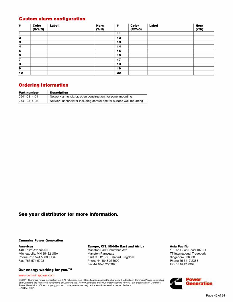
Our energy working for you.™
www.cumminspower.com
©2007|Cummins Power Generation Inc.|All rights reserved|Specifications subject to change without notice|Cummins Power Generation and Cummins are registered trademarks of Cummins Inc. PowerCommand and “Our energy working for you.” are trademarks of Cummins Power Generation. Other company, product, or service names may be trademarks or service marks of others. S-1343e (9/07)
Custom alarm configuration # Color
(R/Y/G) Label Horn
(Y/N) # Color
(R/Y/G) Label Horn
(Y/N)
1 11
2 12
3 13
4 14
5 15
6 16
7 17
8 18
9 19
10 20
Ordering information
Part number Description
0541-0814-01 Network annunciator, open construction, for panel mounting
0541-0814-02 Network annunciator including control box for surface wall mounting
See your distributor for more information. Cummins Power Generation
Americas 1400 73rd Avenue N.E. Minneapolis, MN 55432 USA Phone: 763 574 5000 USA Fax: 763 574 5298
Europe, CIS, Middle East and Africa Manston Park Columbus Ave. Manston Ramsgate Kent CT 12 5BF United Kingdom Phone 44 1843 255000 Fax 44 1843 255902
Asia Pacific 10 Toh Guan Road #07-01 TT International Tradepark Singapore 608838 Phone 65 6417 2388 Fax 65 6417 2399
Page 45 of 84
ff028
Rectangle

Page 46 of 84
ff028
Rectangle
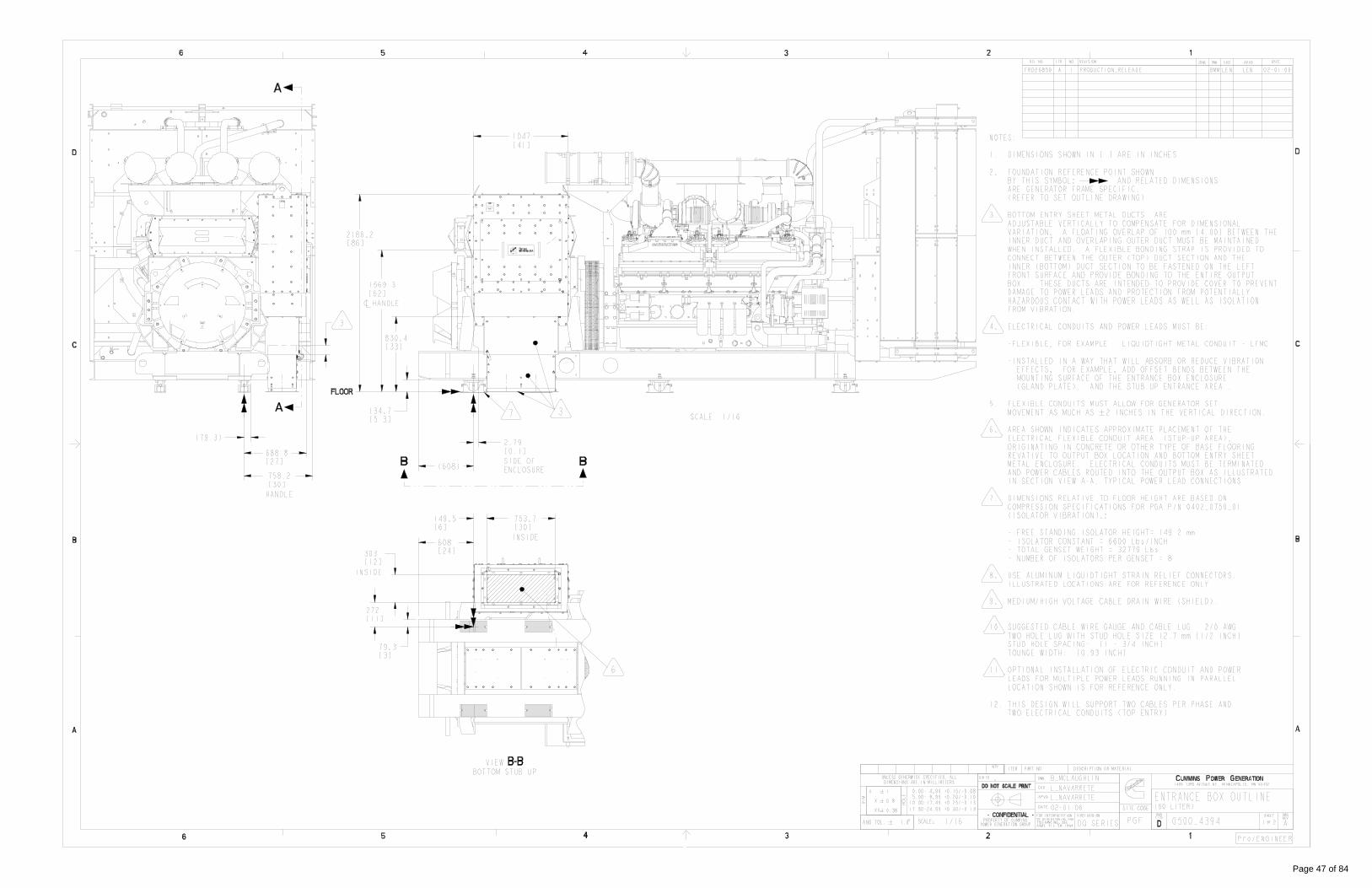
Page 47 of 84
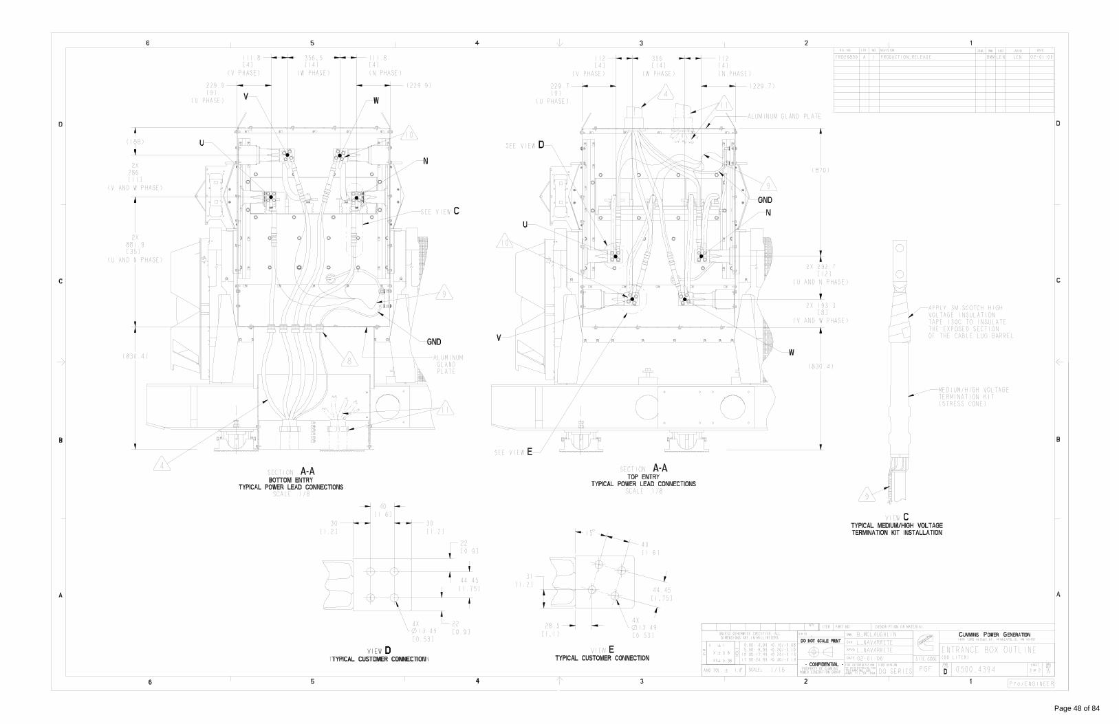
Page 48 of 84

Sheet 1 of 9Part Name: A030Y635 Revision: B
Drawing Name: A030Y636 Revision: BPage 49 of 84
ff028
Rectangle
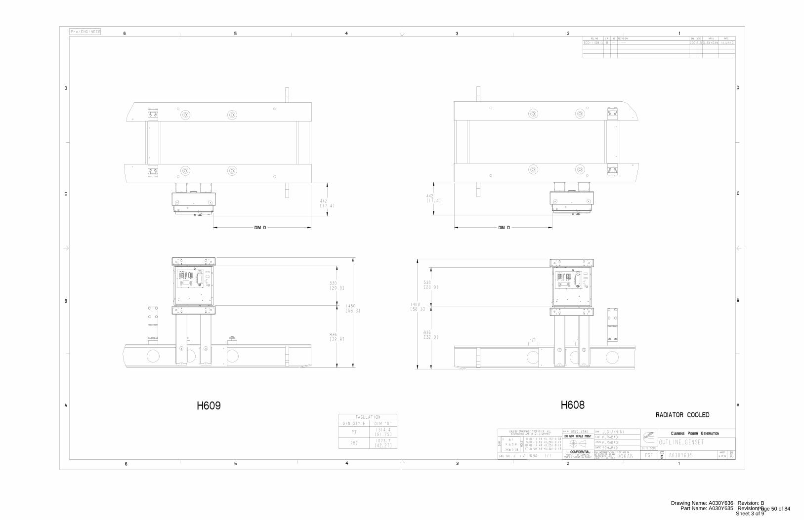
Sheet 3 of 9Part Name: A030Y635 Revision: B
Drawing Name: A030Y636 Revision: BPage 50 of 84
ff028
Rectangle
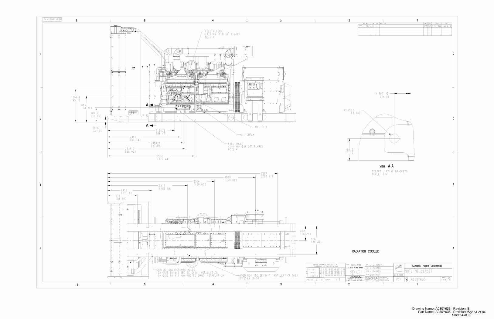
Sheet 4 of 9Part Name: A030Y635 Revision: B
Drawing Name: A030Y636 Revision: BPage 51 of 84