Dielectric Withstand Tester - Compliance West USA · 2 Section 1 An Introduction to Dielectric...
32
Dielectric Withstand Tester HT-10000P Series Models: HT-10000P ac/dc HT-10000P ac HT-10000P dc 0 - 10,000 Volts AC Output 0 - 14,000 Volts DC Output Instruction Manual
Transcript of Dielectric Withstand Tester - Compliance West USA · 2 Section 1 An Introduction to Dielectric...

Dielectric Withstand Tester
HT-10000P Series
Models:
HT-10000P ac/dc
HT-10000P ac HT-10000P dc
0 - 10,000 Volts AC Output 0 - 14,000 Volts DC Output
Instruction Manual


Dear Customer: Congratulations! Compliance West USA is proud to present you with your Dielectric Withstand Tester. Your instrument features a groundbreaking microcontroller circuit design and ergonomic front panel, and represents the latest in high voltage laboratory testing. To fully appreciate all the features of your new meter, we suggest that you take a few moments to review this manual. Compliance West USA stands by your instrument with a full one-year warranty. If the need arises, please don't hesitate to call on us. Thank you for your trust and confidence.
Rev 5.0, January 2013.


Table of Contents
An Introduction to Dielectric Withstand Testing with the HT-10000P ...................................... 2
Leakage Test .................................................................................................................. 2
High Voltage Dielectric Withstand Test ........................................................................ 2
High Voltage Discharge ................................................................................................. 3
Introduction and Specifications ................................................................................................... 4
Operation ..................................................................................................................................... 6
Setting up the HT-10000P .............................................................................................. 6
AC Line Voltage Requirements ..................................................................................... 6
Fuse Replacement .......................................................................................................... 6
Front and Rear Panel Features ....................................................................................... 6
Options ........................................................................................................................... 13
Safety Interlock (XI) ......................................................................................... 13
Voltage on Failure (VF) .................................................................................... 13
Auto Reset on Pass (AR) ................................................................................... 13
Zero Voltage Start (ZOS) .................................................................................. 13
Relay Isolated Remote Interface (RI) ................................................................ 13
Initial Checkout Procedure ............................................................................................. 15
Factory Settings ................................................................................................. 16
Voltage Type Selection (HT-10000P ac/dc) ..................................................... 16
Display of Leakage Limit and Duration settings .............................................. 16
Leakage Current Level Adjust .......................................................................... 16
Ramp Time Adjust ............................................................................................ 16
Voltage Adjust .................................................................................................. 17
High Voltage Test Time Adjust ........................................................................ 17
Setting the Voltage Ramp Switch ..................................................................... 18
Setting the Test Timer Switch ........................................................................... 18
Setting the Failure Shutdown Switch ................................................................ 18
Operating Techniques .................................................................................................... 19
Testing Products ................................................................................................ 19
Test Results ....................................................................................................... 20
Maintenance and Calibration ...................................................................................................... 22
Service Information ........................................................................................................ 22
Cleaning ......................................................................................................................... 22
Calibration Procedure..................................................................................................... 22
Entering Calibration Mode ................................................................................ 23
Calibration and Software Version Information ................................................. 23
Voltage Meter Verification ............................................................................... 24
Voltage Meter Re-Calibration ........................................................................... 24
Leakage Meter Verification only for AC or DC Models .................................. 25
Leakage Meter Verification only for AC/DC Model ........................................ 25
Leakage Current Re-Calibration ....................................................................... 26
Technical Assistance ................................................................................................................... 27

1
2
Section 1
An Introduction to Dielectric Withstand Testing with the HT-10000P
The dielectric withstand test is a test which is recognized by safety agencies worldwide
as a valid criterion of safe assembly of end-use equipment. The HT-10000P is designed as a
research instrument to determine the dielectric properties of component assemblies of end-use
equipment. It applies a high-voltage potential between Output and Return test leads and
monitors Leakage Current and watches for Dielectric Breakdown during the test. To aid in
testing, the HT-10000P can be configured with or without voltage ramp time, with or without a
test duration timer, and can be set to deliver high voltage after an arc has been detected to
pinpoint an area of arcing.
The dielectric withstand test involves high voltage and caution should be exercised when
using the HT-10000P. The Return Receptacle on the front panel is connected to ground
potential, and setups should be designed with this in mind, to guard against the operator
contacting high voltage. Always make sure the return lead is firmly connected.
Leakage Test
The HT-10000P leakage test uses a separate low-frequency circuit to detect excessive
current between the Output and Return receptacles on the front panel. There is not a specific
leakage current level pass/fail requirement at this time for most equipment. However, higher
than normal leakage current on a particular sample may indicate an assembly or component
problem in the circuit.
The leakage current is also monitored by the HT-10000P to ensure that excessive leakage
does not keep the tester from developing full voltage required for the high voltage test. The HT-
10000P will provide full voltage at any leakage current level up to 5mA in DC and 10mA in AC.
Set the acceptable leakage current limit using the Shutdown Limit Potentiometer on the front
panel. The Shutdown Limit Switch must be set to ON or the HT-10000P keep testing regardless
of Leakage Current. Voltage output may sag under these conditions.
If the green Full Voltage indicator lights and the test continues, the leakage current was
below the acceptable limit. If the red Excess Leakage indicator lights, the buzzer sounds,
and the test is terminated; the leakage current was above the acceptable limit.
High Voltage Dielectric Withstand Test
This test checks for insulation system breakdowns by applying a high voltage between
the Output and Return receptacles on the front panel. The HT-10000P uses a separate high-
frequency circuit to detect arc breakdowns.
Set the test duration with the Timer Control Potentiometer on the front panel. The test
time is counted from the time the Full Voltage indicator is lit to the completion of the test. The
Timer Control Switch must be set to ON or the HT-10000P will test only while the Test Button is
3
pressed. The minimum test time is one second regardless of the setting of the Timer Control
Switch.
If the green Hipot Pass indicator lights, the test cycle has been successfully completed,
meaning there was no dielectric breakdown. If the red Hipot Fail indicator lights, a
breakdown arc has been detected.
High Voltage Discharge
The HT-10000P has an internal ramp down circuit designed to discharge the high voltage after
completion of the dielectric withstand test. The HT-10000P should remain connected to the circuit until the
front panel meter shows that the output voltage has dropped to a safe level.

4
Section 2
Introduction and Specifications
This manual contains complete operating and specifications for the HT-10000P
Dielectric Withstand Tester.
The instrument is a bench-type Dielectric Withstand Tester with AC or DC Output,
designed for laboratory testing of components and insulation systems.
The HT-10000P features automatic one button operation, with numerous safety features
designed to protect the operator:
- The test return lead is directly connected to ground potential for operator safety.
- The test can be immediately terminated at any time by pressing the red RESET button.
- Before the test can commence, the unit must be armed by pressing the red RESET
button. The test will not begin until the blue TEST Button is pushed.
- If a failure is encountered, the high voltage is immediately shut down, a buzzer sounds
and the voltage discharge progress is shown by the front panel meter.
- Failure modes are shown by the front panel LED's.
Convenience and testing features include:
- Voltage ramp, test time and leakage limit are settable.
- Voltage ramp and test duration timer are defeatable for specialized testing.
- Testing may terminated or continued when a dielectric breakdown is detected.
- Test results are determined quickly, without operator intervention.
- The HT-10000P allows custom setups for voltage ramp, test time and leakage limit.
Your Tester has a warranty for a period of one year upon shipment of the instrument to the
original purchaser.
ELECTRICAL
Voltage Output AC: 0 – 10000 V
DC: 0 – 14000 V
Max Leakage Current Output AC: 0 - 8000V=10mA, 10000V=8mA
DC: 0 - 10000V=5mA, 13000V=1mA
Leakage Current Limit Adjustment AC: 1.0 – 10.0 mA
DC: 1.0 – 5.0 mA
Leakage Adjustment Resolution 0.1 mA steps
Pass/Fail Criteria:
Leakage Current: Pass/Fail point user adjustable.
Dielectric Breakdown: Separate high frequency detection circuit for
breakdown spike detection
Table 2-1. HT-10000P ac/dc Specifications (continue next page…)

5
ELECTRICAL (Continuation)
Test Time: User adjustable 1->60 sec, defeatable
Voltage Ramp-up Time: User adjustable 1-5 sec., defeatable
Voltage Ramp-down Time: AC: < 7 mS
DC: < 8 S
Meter accuracy AC: ± 100V from 500 - 10000 V
DC : ± 100V 500 - 14000 V
Current Meter accuracy ± 0.1 mA (AC/DC model only)
Duty cycle 100 %
Test adjustments Ramp Time
Test Time
Leakage Limit
Voltage Adjust
Ramp ON/DEFEAT
Timer ON/DEFEAT
Hipot ON/DEFEAT
OPTIONS
(XI) Safety Interlock Two position terminal block on rear panel must be
shorted for high voltage operation.
(VF) Voltage on Failure If failure as Excess Leakage or Hipot Fail happens, it
will terminate the test and the front voltage display
will hold the last voltage reading.
(AR) Auto Reset on Pass Resets the HT-10000P after a few seconds only on
passing test condition.
(ZOS) Zero Voltage Start Voltage adjust knob must be to minimum position to
allow start the test cycle.
(RI) Relay Isolated Remote Interface It allows the interface with a PLC or other machine
using relay closures. This option allows isolation
between the PLC and the Hipot tester.
ENVIRONMENTAL
Operating Temperature 15-40°C
Relative Humidity Range 0-90% non-condensing
GENERAL
Input power requirements 120volts, 50/60 Hz, 2A max *optional different line voltages available (100V, 110V, 220V, 230V, 240V) Weight AC/DC 29 lbs
AC or DC only 19 lbs
SAFETY AGENCY TOPICS
Transformer Output < 500VA
Visual Indication of Voltage Output Provided by front panel meter, directly connected to
high voltage output
Failure Indication Audible, provided by internal buzzer
Visual, provided by red LEDs on front panel
Test can be automatically terminated on failure
Leakage Test Provided; 5 mA AC factory set pass/fail point, user
adjustable.
Table 2-1. HT-10000P ac/dc Specifications (Continuation…)

6
Section 3
Operation
This section describes how to set up and make measurements with the HT-10000P unit.
We recommend that you read the entire section carefully so that you can use all of its features.
Setting up the HT-10000P
The HT-10000P is shipped in a special protective container that should prevent damage
during shipping. The container should include the following:
• The HT-10000P Dielectric Withstand Tester.
• A black 18 AWG Return Test Lead with alligator Clip/Banana Plug ends (GL)
• Red 18 AWG High Voltage Test Lead alligator Clip/High Voltage Plug ends (HVL5).
• 18 AWG AC Power Cord (70-101).
• This Instruction Manual.
18 AWG Line Power
Cord
GL Return Test Lead Red 18 AWG High
Voltage Test Lead
Shipment Cables
Use the original shipping container for subsequent shipping. If the original shipping
container is not available, be sure that adequate protection is provided to prevent damage during
shipment.
AC Line Voltage Requirements
Connect the HT-10000P only to a voltage source per the rating on the rear panel.
Fuse Replacement
For AC/DC model, there is a user-replaceable fuse located on the front panel with the
rating printed. For the AC or DC only, the fuse is behind a door in the Inlet-Power Switch-Fuse
Holder device located the rear panel. For continued protection against risk of fire, replace only
with same type and rating of fuse.
Front and Rear Panel Features
Before using the HT-10000P tester, take a few minutes to become familiar with the use
of its controls, indicators, and connectors. The features for ac/dc model are shown in Figure 3-1,
& Table 3-1. Features for ac or dc only are shown on figures 3-2, 3-3, and tables 3-2, 3-3.

7
Figure 3-1. Controls, Indicators, Connectors - Model HT-10000P ac/dc Front Panel

8
ITEM NO. NAME FUNCTION
1 HIPOT switch
When ON, Dielectric breakdown detect will be activated.
When in DEFEAT position, test will continue regardless of a dielectric breakdown, but it can be stopped by the
excess leakage limit. NOTE: The RAMP switch, and TIMER switch must also be in the DEFEAT position,
otherwise the buzzer will sound. The test will continue only as long as the TEST button is pressed. Minimum test
time is approximately one second.
2 TIMER switch
When ON, test duration is set by TIMER ADJUST, Item 5.
When in DEFEAT position, testing continues only as long at TEST button is pressed. Minimum test time is one
second. NOTE: TIMER Switch position must be DEFEAT when HIPOT Switch is in the DEFEAT position.
3 RAMP switch
When ON, Voltage ramp up time is controlled by RAMP ADJUST, Item 6.
When in DEFEAT position, high voltage is applied immediately when TEST button is pressed. NOTE: RAMP
Switch position must be DEFEAT when HIPOT Switch is in the DEFEAT position.
4 LEAKAGE ADJUST Adjusts the shutdown point for the Leakage Current Test. For details see “Leakage Current Adjust.”
5 TIMER ADJUST Adjusts the test duration. For details see “Test Time Adjust”.
6 RAMP ADJUST Adjusts the delay between time TEST button is pushed and time desired output voltage is attained. For details see
“Ramp Time Adjust”. For no delay, DEFEAT Ramp Time Switch, Item 3.
7 AC/DC Switch Selects AC or DC output. Operates only when RESET or TEST switch is lit – does not function during a test.
8 RESET Button When lit, indicates that the HT-10000P ac/dc is unarmed. When the RESET Button is pressed, the TEST switch is
lit. PRESSING THE RESET BUTTON AT ANY TIME IMMEDIATELY STOPS TESTING.
9 TEST Button When lit, indicates the HT-10000P ac/dc is ready to test; press to begin testing.
10 VOLTAGE METER Connected to the output. Reads actual output voltage. Adjust meter with VOLTAGE ADJUST Knob, Item 19.
11 HIPOT PASS LED Indicates test conclusion with satisfactory results.
12 FULL VOLTAGE LED Lights when output voltage has ramped up. Test time starts when this indicator lights.
13 HIPOT FAIL LED Lights when arcing or insulation flashover has occurred.
14 EXCESS LEAKAGE LED Actual leakage current has exceeded the leakage point set with Leakage Limit Potentiometer, Item 4.
15 CURRENT METER Connected to the output. Reads the current flowing through the return lead of the HT-10000P ac/dc during the test.
16 AC OUTPUT Receptacle Connect high voltage lead here to conduct an AC test.
17 DC OUTPUT Receptacle Connect high voltage lead here to conduct a DC test.
18 RETURN Receptacle At chassis ground reference level. Connect black return lead here.
19 VOLTAGE ADJUST Knob Voltage is continuously adjustable during testing with this knob.
20 AC POWER Switch Energize the HT-10000P ac/dc.
21 FUSE Mains fuse. Replace only with type and rating of fuse specified on the front panel label. Turn off power switch,
Item 20, before servicing fuse.
Table 3-1. Controls, Indicators, Connectors - Model HT-10000P ac/dc Front Panel
9
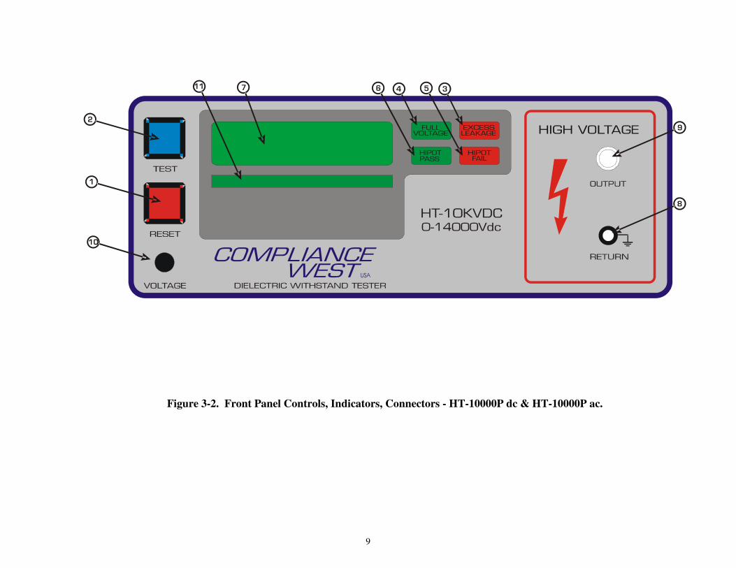
Figure 3-2. Front Panel Controls, Indicators, Connectors - HT-10000P dc & HT-10000P ac.

10
ITEM NO. NAME FUNCTION
1 RESET Button
When lit, indicates that the HT-10000P is unarmed. This button must be pushed before the TEST Button is functional.
When the RESET Button is pressed, the red lamp goes out and the blue TEST lamp is lit. PRESSING THE RESET
BUTTON AT ANY TIME STOPS THE TEST.
2 TEST Button When lit, indicates that the HT-10000P is ready to test. Press to begin testing.
3 EXCESS LEAKAGE LED Indicates failure of leakage current test. If leakage current is too high, the red LED will light and the internal buzzer
will sound.
4 FULL VOLTAGE LED The full voltage LED will light and if not defeated, the high voltage duration time starts when the voltage output reaches
the preset level.
5 HIPOT FAIL LED
Indicates failure of high voltage test. If arcing or a flashover of the insulation system is detected, the red breakdown
LED will light, the internal buzzer will sound. The test may be terminated depending on the setting of the Failure
Shutdown Switch.
6 HIPOT PASS LED
At the preset test duration time, if no insulation breakdowns are encountered, the green light will light and the test will
terminate. If the Test Timer Switch is defeated, testing continues only while the Test Button is pressed (minimum test
time one second).
7 VOLTAGE Display Visual indication of the actual output voltage.
8 RETURN Receptacle Grounded banana plug jack. For Return Lead connection.
9 OUTPUT Receptacle Red High Voltage jack. For connection of high voltage test lead.
10 Voltage Adjust Knob Voltage is continuously adjustable during test.
11 Ramp Bars Visual status for the Ramp output circuit.
Table 3-2. Controls, Indicators, Connectors - HT-10000P dc & HT-10000P ac Front Panel

11
Figure 3-3. Controls, Indicators, Connectors HT-10000P dc & HT-10000P ac Rear Panel
12
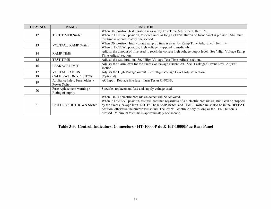
ITEM NO. NAME FUNCTION
12 TEST TIMER Switch
When ON position, test duration is as set by Test Time Adjustment, Item 15.
When in DEFEAT position, test continues as long as TEST Button on front panel is pressed. Minimum
test time is approximately one second.
13 VOLTAGE RAMP Switch When ON position, high voltage ramp up time is as set by Ramp Time Adjustment, Item 14.
When in DEFEAT position, high voltage is applied immediately.
14 RAMP TIME Adjusts the amount of time used to reach the correct high voltage output level. See "High Voltage Ramp
Time Adjust" section.
15 TEST TIME Adjusts the test duration. See "High Voltage Test Time Adjust" section.
16 LEAKAGE LIMIT Adjusts the alarm level for the excessive leakage current test. See "Leakage Current Level Adjust"
section.
17 VOLTAGE ADJUST Adjusts the High Voltage output. See "High Voltage Level Adjust" section.
18 CALIBRATION RESISTOR (Optional).
19 Appliance Inlet / Fuseholder /
Power Switch
AC Input. Replace line fuse. Turn Tester ON/OFF.
20 Fuse replacement warning /
Rating of supply
Specifies replacement fuse and supply voltage used.
21 FAILURE SHUTDOWN Switch
When ON, Dielectric breakdown detect will be activated.
When in DEFEAT position, test will continue regardless of a dielectric breakdown, but it can be stopped
by the excess leakage limit. NOTE: The RAMP switch, and TIMER switch must also be in the DEFEAT
position, otherwise the buzzer will sound. The test will continue only as long as the TEST button is
pressed. Minimum test time is approximately one second.
Table 3-3. Control, Indicators, Connectors - HT-10000P dc & HT-10000P ac Rear Panel

13
Options
This section contains a list and descriptions of available factory installed options at the
time of this printing.
Code Description
XI Safety Interlock
VF Voltage on Failure AR Auto Reset on Pass
ZOS Zero Voltage Start
Safety Interlock (XI)
Safety Interlock is an optional feature that utilizes a set of closed contacts to enable the
instrument. If the Safety Interlock contacts are open before or during the test, the output of the
instrument will be disabled and the front display meter will show “int”, indicating that the
external interlock is open..
Voltage on Failure (VF)
The Voltage on Failure is an optional feature which captures the voltage reading at the
moment of a breakdown or excess leakage failure. If a failure happens, the test will terminate
immediately, buzzer will sound but the voltage reading at the failure point will be hold on the
same voltage meter until the reset button is pressed. If failure is not detected, the test will
terminate and the voltage meter will display 0 volts. Note: it is recommended to set the ramp
time potentiometer to the maximum in order to improve the accuracy of the Voltage on Failure
option.
Auto Reset on Pass (AR)
Auto Reset on Pass is an optional feature which automatically resets the Hipot unit into a
ready to test state. If the test is completed with a green Hipot Pass light, the unit will reset
automatically after 1 second. If a failure happened, the test will terminate immediately, the
buzzer will sound, and the respective red failure light will be On until the reset button is pressed.
Zero Voltage Start (ZOS)
The Zero Voltage Start is and optional safety feature which require setting the voltage
adjust knob to the minimum level in order to allow start a new test cycle. Note: This option will
bypass the Ramp Time Adjustment feature of the equipment.
Relay Isolated Remote Interface (RI)
The Relay Isolated Remote Interface is an option that allows the Hipot Tester to interface
with a PLC or other machine using relay closures. This option allows isolation between the PLC
and the Hipot Tester. Up to five relays are available for the transferring the following states:

14
• Full Voltage
• Excess Leakage
• Hipot Pass (indicates overall Test Pass)
• Hipot Fail
• Any Failure
In addition, tests can be remotely started and stopped by sending a signal to the Hipot tester.
Signal voltage can be chosen from the following:
• 5 Vdc
• 12 Vdc
• Other
Output connector style can be a DB-9, DB15, Terminal Block; or if you have a custom relay
block you would like to use, it can be installed for you.

15
Initial Checkout Procedure
Use this procedure to verify that the HT-10000P tester is working correctly. Refer to
tables 3-1, 3-2, 3-3 and figures 3-1, 3-2, 3-3 for location of items.
CAUTION
High voltage, risk of shock, use with care.
1. Turn the Tester on using the AC Power switch.
2. Select the voltage type using the AC/DC Voltage Switch (only AC/DC model).
3. Set the Voltage Ramp switch, Test Timer switch, and Failure Shutdown switch to ON
position.
4. Disconnect leads from the Output and Return jacks.
5. Set the Test Time to 30 seconds.
6. Push the RESET button. The TEST button should light.
7. Push the TEST button.
8. The HT-10000P tester will conduct a test. The meter will read a voltage, hold, and return to
zero. During the test, the voltage can be adjusted using the Voltage Adjustment knob. At the
end of the test, the Full Voltage, Hipot Pass, and RESET switch indicators should be lit.
9. Connect the black lead to the Return receptacle and the red lead to the proper AC or DC
Output receptacle selected on step 2.
10. Connect the two leads together to simulate a high leakage current condition. Push the RESET
button and then push the TEST button.
11. Test should terminate immediately and the buzzer should sound. The Excess Leakage
Indicator and RESET button indicators should be lit. If a spark occurred, the Hipot Fail
indicator will also be lit.
12. Leaving the red and black leads connected together, disconnect the red lead from the HT-
10000P.
13. Enable the voltage output by pressing the RESET button, then the TEST button. When the
full voltage indicator lights, adjust the Voltage knob so the output is approx. 5000 volts.
Press the RESET button to disable high voltage output.
14. Verify that the red and black leads are connected together, the black lead is connected to the
Return receptacle, and the red lead is disconnected from the HT-10000P.
15. (This test simulates a dielectric breakdown. High voltage could exist on the alligator clips.
Exercise caution to avoid shock.) Push the RESET button, then the TEST button. After the
full voltage indicator lights, pick up the red lead and insert it into the proper AC or DC HV
Output selected on step 2. The test will immediately terminate with a buzzer. The Full
Voltage, Hipot Fail, and RESET button indicators should be lit.
16. Adjust the voltage and time to the desired settings
If any of these tests give unexpected results, service may be required. Please check the
test setup and if further information is needed, contact our Service hotline for assistance.

16
Factory Settings
The HT-10000P is configured as shown when shipped from Compliance West USA:
Voltage Type (HT-10000P ac/dc): AC
Leakage Current Level: 5 mA
High Voltage Ramp Time: Minimum
High Voltage Level: Minimum
High Voltage Test Time: 1 second
Voltage Ramp Switch: ON
Test Timer Switch: ON
Breakdown Detect Switch: ON
Voltage Type Selection (HT-10000P ac/dc)
Use the AC/DC Voltage Switch. This switch is functional only when the RESET or
TEST button is lit.
Display of Leakage Limit and Duration settings
To view the Test Duration and Leakage Limit current settings, hold down the RESET
button for 2 seconds. The meter will display “L” with the Leakage Limit value in mA. Hold
down the RESET button again for 2 seconds and the meter will display “d” with the Test
Duration set time in seconds.
Leakage Current Level Adjust
1. Connect the HT-10000P to a correctly rated source of supply and turn ON the tester.
2. Push the RESET button. The TEST indicator should light, indicating that the HT-10000P is
ready.
3. Turn the Leakage Limit Adjust. As soon as the potentiometer starts turning, the meter will
start blinking, display “L”, and the value can be set in 0.1 mA increments.
Ramp Time Adjust
When option Zero Voltage Start is ordered, the voltage knob adjustment will need to start
always from minimum setting bypassing the Ramp Time Adjustment setting .
This procedure sets the high voltage ramp time between 0.5 and 5 sec. The factory
setting of one second is adequate for most situations. However, DC testing into a larger
capacitive loads may cause a shutdown due to excessive leakage current. In this case, increasing
the ramp time may solve the problem.
1. Make sure there are no test leads connected to the Tester.
2. Set the Voltage Ramp Switch to ON.
3. Set the Test Timer Switch to ON.
4. Set the Failure Shutdown Switch to ON.

17
5. Push the RESET button, then the TEST button.
6. The FULL VOLTAGE indicator will light. The time from when the TEST button is pushed
to when the FULL VOLTAGE indicator lights is the Ramp Time. Set the Ramp Time
Potentiometer to change the ramp time. Repeat until the desired Ramp Time is set.
Voltage Adjust
Note
When option Zero Voltage Start is ordered, the voltage knob adjustment will need to start
always from minimum setting.
This procedure controls the high voltage level used in the dielectric withstand test. The
HT-10000P is factory set for minimum voltage as shipped from the factory. Use the procedure
below to set it.
1. Make sure there are no leads connected to the tester.
2. Set the Voltage Ramp Switch to ON.
3. Set the Test Timer Switch to DEFEAT.
4. Set the Failure Shutdown Switch to ON.
5. Turn the Voltage Adjust knob to Zero(counterclock wise).
6. For HT-10000Pac/dc use the AC/DC Switch for the desired output voltage.
7. Push the RESET button.
8. Push and hold the TEST button. Voltage will be supplied while the TEST button is pressed.
9. After the FULL VOLTAGE indicator lights, use the Voltage Adjust knob to set the desired
voltage output.
10. Release the TEST button to terminate the test.
High Voltage Test Time Adjust
This procedure sets the length of time the HT-10000P will conduct the high voltage test.
The test time is specified by the safety agencies and is tied to the test voltage. Most safety
agencies will allow a much shorter test (usually 1 second vs. 1 minute) if the voltage is increased
by 20%. The factory set for 1 seconds. Consult the safety agencies for the test time for the type
of equipment being tested. If a different test time is required, use this procedure to set it.
1. Connect the tester to a correctly rated source of supply and turn ON the power switch.
2. Push the RESET button. The TEST indicator should light, indicating that the HT-10000P
is ready.
3. Adjust the Test Time potentiometer. As soon as the potentiometer starts turning, the meter
will display “d” and the value can be set in 1 second increments from 1 to 60 seconds.

18
Setting the Voltage Ramp Switch
Note
When option Zero Voltage Start is ordered, the voltage knob adjustment will need to start
always from minimum setting.
When this switch is in the DEFEAT position, the voltage will immediately rise to the
level set by the Voltage Adjust knob. The Ramp Control setting is ignored.
When this switch is in the ON position, the voltage ramps according to the setting of the
Ramp Potentiometer. See adjustment instructions above. The Voltage Ramp Switch must be
defeated if Shutdown Limit Defeat is desired. See Table 3-4 for details.
Setting the Test Timer Switch
The Timer Control switch allows test time to be controlled by the HT-10000P internal
timer or to continue until terminated by the operator.
When this switch is in the DEFEAT position, the test will continue only while the TEST
button is held down. The minimum test time is approx. 1 second.
When this switch is in the ON position, the test time will be controlled by the HT-
10000P internal timer. For information on how to set this time, see instructions above.
The Test Timer must be defeated if Breakdown Detect Defeat is desired. See Table 3-4
for details.
Setting the Failure Shutdown Switch
Use extreme caution when using this feature
The Breakdown Detect switch allows the operator to continue testing after a failure is
encountered. This allows the operator to find the breakdown point, but all arc shutdown
circuitry in the HT-10000P is disabled when the Breakdown Detect switch is in the
DEFEAT position. The excess leakage limit may stop the test. Also the tests may be terminated
at any time by releasing the TEST button.
WARNING: Testing with the Shutdown Limit switch in the DEFEAT position is
extremely hazardous. The HT-10000P can generate lethal levels of voltage and current.
Therefore, care should be taken in examining the equipment being tested, to locate areas of
failure while the HT-10000P is operating.
19
Operating Techniques
The following paragraphs describe how to operate the HT-10000P Dielectric Withstand
Tester.
CAUTION:
High voltage is generated by the HT-10000P. Although the chassis of the
equipment under test is grounded by the HT-10000P, a risk of shock exists. Exercise
care when using the HT-10000P.
Testing Products
This section describes how to conduct a test. Testing can be terminated at any time by
pressing the RESET button.
1. Set up tester to correct parameters for unit to be tested using the previously described
procedures.
2. Connect the HT-10000P to a correctly rated source of supply and turn it on.
3. Plug the black lead into the Return receptacle. Plug the red lead into the Output receptacle.
For HT-10000P ac/dc plug the red lead into the AC or DC Output receptacle and set the
AC/DC switch accordingly.
4. Connect the alligator clips of the leads across the circuit or part being tested. Keep in mind
that the black lead is connected to earth ground.
5. Press the RESET button, the TEST button should light, indicating that the HT-10000P is
ready to test.
6. Push the TEST button. The HT-10000P will either:
• Ramp the voltage at the rate set by the Ramp Time Procedure, if the Ramp Control
switch is set to ON.
• Immediately energize the high voltage output if the Ramp Control Switch is set to
DEFEAT.
7. If the Shutdown Limit switch is set to ON, and if the leakage current of the circuit under
test exceeds the alarm value, the Excess Leakage indicator will light and the test will
terminate.
If the Shutdown Limit switch is set to DEFEAT, and the requirements of Table 3-4 are
met, the HT-10000P will continue to test. Voltage output may sag if the power required by
the circuit is beyond the capabilities of the HT-10000P.
8. If the Timer Control switch is set to ON, the HT-10000P will conduct the high voltage test
for the amount of time set in the Test Duration procedure.
If the Timer Control switch is set to DEFEAT, the high voltage test will continue only
while the TEST button is pressed.
9. If a insulation system breakdown is detected, and
• The Shutdown Limit switch is ON, the Hipot Fail indicator will light, the buzzer will
sound, the voltage will ramp down to a safe level, and the test will terminate.
• The Shutdown Limit switch is set to DEFEAT, and the requirements of Table 3-4 are
met, the Hipot Fail indicator will light and the test will continue as long as the TEST
button is pressed.

20
10. If no breakdown is detected, the high voltage will ramp down, the Hipot Pass indicator will
light, and the RESET button will light.
11. Do not disconnect the leads from the equipment being tested until test has terminated, and
the meter indicates zero volts.
Test Results
Hipot Pass: If the Hipot Pass light is lit, the equipment being tested passed all test parameters.
Red Indicator/Buzzer: Any red indicator/buzzer test result means the equipment being tested
failed a test phase. If unanticipated test failures continue, and you suspect that the equipment
under test is built correctly, check the following items:
1. Shutdown / Leakage Limit Setting (AC and/or DC): May be set too low. This would
cause normal input capacitor charging to draw more that the preset leakage current limit,
triggering a Leakage Current Fail light and terminating the test. Consider raising the acceptable
leakage current level; see Adjustment of the Leakage Current Shutdown point.
If the Shutdown Limit level is at its highest setting and failures continue, switch to a DC
test. If failures still continue after switching to a DC test, check the circuit being tested with an
ohmmeter; it may be shorted.
2. Ramp Time (DC tests): May be set too low. A very fast ramp time may allow input
capacitors to charge, triggering a Leakage Current Fail light and terminating the test. Consider
lengthening the ramp time; see Ramp Time Adjust.

21
Switches Result
RAMP TIMER HIPOT ON ON ON Fully automatic operation. When Test button is pressed, the output
voltage will ramp at a rate determined by the position of the TEST
TIME adjustment knob. Test will stop automatically on all leakage
or breakdown failures.
DEFEAT ON ON Voltage Ramp is defeated. Full voltage is produced at the output
immediately. Test will stop automatically on all leakage or
breakdown failures. For safety, we recommend that you begin
testing with the front panel voltage knob set at minimum.
ON DEFEAT ON Test Timer is defeated. After full voltage is reached, the test will
continue only as long as the Test button is held in, minimum one
second. Test will stop automatically on all leakage or breakdown
failures.
DEFEAT DEFEAT ON Full voltage is produced at the output immediately when the Test
button is pressed. The test will continue only as long as the Test
button is held in, minimum one second. Test will stop
automatically on all leakage or breakdown failures. For safety, we
recommend that you begin testing with the front panel voltage
knob set at minimum.
ON ON DEFEAT Buzzer will turn ON, It will not allow to test until all the switches
are in defeat.
DEFEAT ON DEFEAT Buzzer will turn ON, It will not allow to test until all the switches
are in defeat.
ON DEFEAT DEFEAT Buzzer will turn ON, It will not allow to test until all the switches
are in defeat.
DEFEAT DEFEAT DEFEAT Full voltage is produced at the output immediately. Test will
continue only as long as the TEST button is held in, minimum one
second. The HT-10000P will NOT shut down on a dielectric
failure, but the front panel Hipot Fail light will turn ON to indicate
a dielectric breakdown. The Hipot Pass light will not light at the
completion of a successful test. For safety, we recommend, that
you begin testing with the front panel voltage knob set at
minimum. For safety reasons, excessive leakage current, as set by
the Leakage knob, will cause the HT-10000P to shut down.
Table 3-4. Switches Truth Table

22
Section 4
Maintenance and Calibration
WARNING
THESE SERVICE INSTRUCTIONS ARE FOR USE BY QUALIFIED PERSONNEL
ONLY. TO AVOID ELECTRIC SHOCK, DO NOT PERFORM ANY SERVICING
OTHER THAN THAT CONTAINED IN THE OPERATING INSTRUCTIONS UNLESS
YOU ARE QUALIFIED TO DO SO.
This section contains maintenance information for the HT-10000P Dielectric Withstand
Tester. A 1-year calibration cycle is recommended to maintain the specifications given in Section
Service Information
The HT-10000P is warranted to the original purchaser for a period of 1 year. This
warranty does not cover problems due to misuse or neglect.
Malfunctions which occur within the limits of the warranty will be corrected at no
charge. Mail the instrument post paid to the manufacturer. Dated proof of purchase is required
for all in-warranty repairs.
The manufacturer is also available for calibration and/or repair of instruments that are
beyond their warranty period. Contact the manufacturer for a cost quotation. Ship the
instrument and your remittance according to the instructions given by the manufacturer.
Cleaning
CAUTION
Do not use aromatic hydrocarbons or chlorinated solvents for cleaning. These
solutions will react with the plastic materials used in the instrument.
Clean the front panel and case with a mild solution of detergent and a damp sponge.
Clean dust from the PWB with clean, dry, low pressure (<20 psi).
Calibration Procedure
The Calibration Procedure should be performed annually and any time your instrument has been
repaired. The calibration procedure consists of the next sections:
1) Entering Calibration Mode.
2) Calibration and Software Version Information.
3) Voltage Meter Verification.
4) Voltage Meter Re-calibration.
5) Leakage Meter Verification for AC or DC only Models.
6) Leakage Meter Verification only for AC/DC Model.
7) Leakage Current Re-Calibration.

23
NOTE
Allow the instrument to stabilize for approximately five minutes. Perform all
calibration adjustments at an ambient temperature of 23°°°°C ±±±±5°°°°C (73°°°°F ±±±±9°°°°F).
WARNING
CALIBRATION ADJUSTMENTS ARE PERFORMED ON ENERGIZED CIRCUITS.
EXERCISE CAUTION AT ALL TIMES, AND USE A NON-CONDUCTIVE TOOL FOR
ALL ADJUSTMENTS.
Entering Calibration Mode
NOTE
Only enter into this mode if the HT-10000P unit needs a re-calibration on any of the
parameters of Voltage Meter or Leakage.
1. Turn Off the HT-10000P unit.
2. Hold in both the Test and Reset buttons.
3. Turn On the HT-10000P unit.
4. Release the Test button, release the Reset button, press and hold the Reset button, press
and hold the Test button, release the Test button, and then release the Reset button.
5. If the correct sequence was entered, the display will read "Sure", if not, start over at step 1.
6. While "Sure" is displayed on the screen you can:
6.1 Press Reset to exit out of the Calibration Mode and keep all of the currently
programmed calibration settings, or.
6.2 Press Test to enter the Calibration Mode and create new calibration settings. (Be sure
you want to enter the Calibration Mode as this will change the laboratory number so it
will show the calibration was not performed by Compliance West USA).
7. Once the Calibration Mode has been entered, the Reset button toggles between the
calibration menu: Volt, V1, V2, L1, L2, and bars.
Calibration and Software Version Information
This will allow the user to see the version of the software as well as who performed the last
calibration.
1. Turn off the HT-10000P tester.
2. Hold in the Reset button while turning on the tester.
3. The meter will display 3 items:
A) The model number of the tester, 10.P.
B) The version of the software
C) Laboratory number to designate who performed the last calibration:
(1= Compliance West USA, 2= another company)

24
Voltage Meter Verification
1. Turn Off the HT-10000P unit.
2. Turn the Voltage Adjust to minimum.
3. Set up a 1000:1 probe with and external volt meter has is shown on Figure 4-1. For AC/DC
models, use the proper HV output.
4. Turn On the HT-10000P unit.
5. Press the Test button and turn up the Voltage Adjust to compare the front meter of the HT-
10000P unit vs. the external volt meter, tolerance must be ±1 count.
6. If one value is out of the specified tolerances, the HT-10000P unit needs a voltage meter re-
calibration. Follow the Voltage Meter Re-Calibration procedure.
Voltage Meter Re-Calibration
1. Turn Off the HT-10000P unit.
2. Set up a 1000:1 probe with the volt meter has is shown on Figure 4-1. For AC/DC models,
use the proper HV output.
3. Enter to Calibration Mode. See Entering Calibration Mode procedure.
4. Select the top calibration voltage point by pressing the Reset button until V1 is shown on
the front display of the HT-10000P unit.
5. Turn the Voltage Adjust on the front panel to minimum (counterclockwise). Press the Test
button and a voltage number will be displayed on the front panel meter (08.00 for AC or
12.00 for DC). Be careful as the HT-10000P will be putting out voltage at this point.
6. Turn the Voltage Adjust on the front panel clockwise until the output on the external
voltage meter equals the number showed on the front meter of the HT-10000P unit, then,
press the Test button to record the new top calibration voltage point in the internal memory.
The front display on the HT-10000P unit will show "V1" again.
7. Select the bottom calibration voltage point by pressing the Reset button until V2 is shown
on the front display of the HT-10000P unit.
8. Turn the Voltage Adjust on the front panel to minimum (counterclockwise). Press the Test
button and a voltage number will be displayed on the front panel meter (01.00 for AC and
DC). Be careful as the HT-10000P will be putting out voltage at this point.
9. Turn the Voltage Adjust on the front panel clockwise until the output on the external
voltage meter equals the number showed on the front meter of the HT-10000P unit, then,
press the Test button to record the new bottom calibration voltage point in the internal
memory. The front display on the HT-10000P unit will show "V2" again.
10. Turn Off the HT-10000P tester.
11. Confirm the new voltage meter calibration performing again the Voltage Meter
Verification procedure, mentioned before.

25
Figure 4-1. Voltage Measurement with 1000:1 High Voltage probe
Leakage Meter Verification only for AC or DC Models
1. Turn Off the HT-10000P unit.
2. Connect the output of the HT-10000P through a 100 watt high voltage load resistor
(240kΩ) in series with an external current meter returning to the Return jack on the front
panel of the HT-10000P as is shown on figure 4-2.
3. Turn the Voltage knob to minimum.
4. Turn On the HT-10000P unit.
5. Turn the Leakage Limit potentiometer to select and specific value to check (AC model
from 1.0mA to 10mA, DC model from 1.0mA to 5.0mA.)
6. Press the Test button and slowly turn up the voltage watching the current on the external
meter. The "Excess Leakage" failure should come. Reading on the external meter should
be +/- 0.1mA.
7. If one value is out of the specified tolerances, the HT-10000P unit needs a leakage current
re-calibration. Follow the Leakage Current Re-Calibration procedure.
Leakage Meter Verification only for AC/DC Model
1. Turn Off the HT-10000P unit.
2. Connect the output of the HT-10000P through a 100 watt high voltage load resistor
(240kΩ) in series with an external current meter returning to the Return jack on the front
panel of the HT-10000P as is shown on figure 4-2. Use the proper HV output for AC or
DC.
3. Turn the Voltage knob to minimum.
4. Turn On the HT-10000P unit.
5. Turn the Leakage Limit potentiometer to the maximum.
6. Press the Test button and slowly turn up the voltage comparing the leakage current on front
meter with the external meter. Reading on the external meter should be +/- 0.1mA.
7. If one value is out of the specified tolerances, the HT-10000P unit needs a leakage current
re-calibration. Follow the Leakage Current Re-Calibration procedure.
26
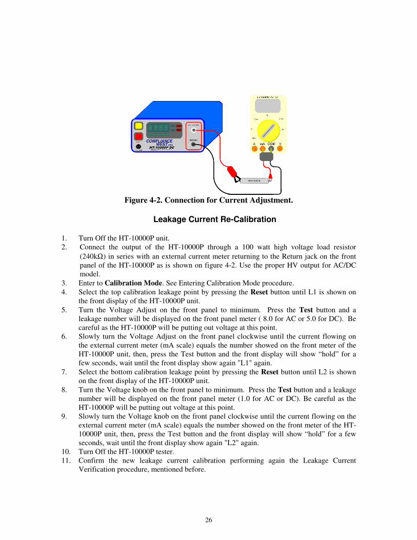
Figure 4-2. Connection for Current Adjustment.
Leakage Current Re-Calibration 1. Turn Off the HT-10000P unit.
2. Connect the output of the HT-10000P through a 100 watt high voltage load resistor
(240kΩ) in series with an external current meter returning to the Return jack on the front
panel of the HT-10000P as is shown on figure 4-2. Use the proper HV output for AC/DC
model.
3. Enter to Calibration Mode. See Entering Calibration Mode procedure.
4. Select the top calibration leakage point by pressing the Reset button until L1 is shown on
the front display of the HT-10000P unit.
5. Turn the Voltage Adjust on the front panel to minimum. Press the Test button and a
leakage number will be displayed on the front panel meter ( 8.0 for AC or 5.0 for DC). Be
careful as the HT-10000P will be putting out voltage at this point.
6. Slowly turn the Voltage Adjust on the front panel clockwise until the current flowing on
the external current meter (mA scale) equals the number showed on the front meter of the
HT-10000P unit, then, press the Test button and the front display will show “hold” for a
few seconds, wait until the front display show again "L1" again.
7. Select the bottom calibration leakage point by pressing the Reset button until L2 is shown
on the front display of the HT-10000P unit.
8. Turn the Voltage knob on the front panel to minimum. Press the Test button and a leakage
number will be displayed on the front panel meter (1.0 for AC or DC). Be careful as the
HT-10000P will be putting out voltage at this point.
9. Slowly turn the Voltage knob on the front panel clockwise until the current flowing on the
external current meter (mA scale) equals the number showed on the front meter of the HT-
10000P unit, then, press the Test button and the front display will show “hold” for a few
seconds, wait until the front display show again "L2" again.
10. Turn Off the HT-10000P tester.
11. Confirm the new leakage current calibration performing again the Leakage Current
Verification procedure, mentioned before.

27
Section 5
Technical Assistance
Technical Assistance from Compliance West USA is available:
Phone: (800) 748-6224
Hours: 8:30 AM - 4:30 PM Pacific Time.
Also available on our web site at: www.compwest.com
Contact:
Compliance West USA
650 Gateway Center Way, Suite D,
San Diego, CA., 92102
United States of America.
Phone: (619) 878-9696
FAX: (619) 794-0404