DICOM Conformance Statement - People Powering … · D.1 RT Plan ... AE Title/Presentation Address...
130
P/N P1012061001 February 2015 DICOM Conformance Statement TrueBeam 2.5 and 4DITC 13.0
Transcript of DICOM Conformance Statement - People Powering … · D.1 RT Plan ... AE Title/Presentation Address...
P/N P1012061001
February 2015
DICOM Conformance Statement
TrueBeam 2.5 and 4DITC 13.0

General Information
2 of 130 TrueBeam 2.5 and 4DITC 13.0 DICOM Conformance Statement, P1012061001
Abstract This document provides information about the DICOM Conformance of TrueBeam® Treatment Console 2.5 and 4D Integrated Treatment Console 13.0.
Manufacturer and European Representative
Manufacturer:
Varian Medical Systems, Inc. Ltd. 3100 Hansen Way, Bldg. 4A Palo Alto, CA 94304-1030, U.S.A.
European Representative:
Varian Medical Systems UK Ltd. Gatwick Road, Crawley West Sussex RH10 9RG United Kingdom
Notice Information in this document is subject to change without notice and does not represent a commitment on the part of Varian. Varian is not liable for errors contained in this document or for incidental or consequential damages in connection with the furnishing or use of this material. This document contains proprietary information protected by copyright. No part of this document may be reproduced, translated, or transmitted without the express written permission of Varian Medical Systems, Inc.
Trademarks ARIA®, TrueBeam®, Varian®, VMS® are registered trademarks.
ARIA™is trademark of Varian Medical Systems, Inc.
Microsoft, Windows NT and Windows are registered trademarks of Microsoft Corporation.
All other trademarks or registered trademark are the property of their respective owners.
General Information
TrueBeam 2.5 and 4DITC 13.0 DICOM Conformance Statement, P1012061001 3 of 130
Contacting Support Support services are available without charge during the initial warranty period. If you seek information not included in this publication, call Varian Medical Systems support at the following locations:
United States and Canada telephone support — + 1 888 827 4265
United States and Canada Direct telephone support — + 1 650-213-1000
European telephone Support — + 41 41 749 8844
Fax (US) — + 1 702 938 4754
Fax (Service Europe) — + 41 41 740 3340
All other countries please call your local service office
To contact the support location nearest you for Service, Parts or Support, see the list at the Varian Medical Systems website:
Worldwide Listing — http://www.varian.com/us/oncology/services_and_support/contacts.html
Communicating Via the World Wide Web If you have access to the Internet, you will find Varian Medical System support at the following location:
Oncology Systems — http://my.varian.com
If you have a Varian account, enter your username and password. Otherwise, first click create new account to get a username and password.
From MyVarian home page, click Contact Us from the Support list along the left side of the window.
If possible, please send all e-mail inquires through the my.varian.com web site at http://my.varian.com/contactus; otherwise, use the following e-mails addresses for support:
Sending E-Mail North America (North America
and Canada) [email protected]
Central & South America [email protected]
Europe (Europe, Middle East, Africa)
Australia (Australian, New Zealand, Australasia)
China / Asia (China, Asia) [email protected]
Japan [email protected]
Brachy Therapy Systems [email protected]
Copyright 2015 Varian Medical Systems Inc., Oncology Systems All rights reserved.
General Information
4 of 130 TrueBeam 2.5 and 4DITC 13.0 DICOM Conformance Statement, P1012061001
Document History
1.0.00 Feb 26, 2015 Initial version for TrueBeam Treatment Console 2.5 and 4D Integrated
Treatment Console 13.0.
Contents
TrueBeam 2.5 and 4DITC 13.0 DICOM Conformance Statement, P1012061001 5 of 130
Contents
Contents ............................................................................................................................. 5
List of Figures .................................................................................................................... 7
List of Tables ...................................................................................................................... 7
1. Introduction .................................................................................................................. 9 1.1 Audience ........................................................................................................................................... 9 1.2 Overview ........................................................................................................................................... 9 1.3 Remarks ........................................................................................................................................... 9 1.4 References ....................................................................................................................................... 9 1.5 Abbreviations .................................................................................................................................. 10
2. Networking ................................................................................................................. 11 2.1 Implementation Model .................................................................................................................... 11
2.1.1 Application Data Flow ........................................................................................................ 11 2.1.2 Functional Definition of AE’s .............................................................................................. 14 2.1.3 Sequencing of Real-World Activities ................................................................................. 14
2.2 AE Specifications ............................................................................................................................ 15 2.2.1 Varian V&R Console Entity ................................................................................................ 15 2.2.2 Association Acceptance Policy .......................................................................................... 28
2.3 Communication profiles .................................................................................................................. 31 2.3.1 Supported communications stacks .................................................................................... 31
2.4 Configuration .................................................................................................................................. 31 2.4.1 4DITC DICOM Configuration ............................................................................................. 31 2.4.2 TXA DICOM Configuration ................................................................................................ 32
3. Media Interchange ..................................................................................................... 33
4. Support of Extended Character Sets ....................................................................... 34
5. Security ...................................................................................................................... 35 5.1 Security Profiles .............................................................................................................................. 35 5.2 Association Level Security ............................................................................................................. 35 5.3 Application Level Security .............................................................................................................. 35
Appendix A Specialization .......................................................................................... 37 A.1 IOD Contents .................................................................................................................................. 37
A.1.1 Created SOP Instances ..................................................................................................... 37 A.1.2 Usage of Attributes from received IOD’s ........................................................................... 37
A.2 Data Dictionary of Private Attributes .............................................................................................. 39 A.2.1 Privatization for RT Plan Storage SOP class .................................................................... 39 A.2.2 Privatization for RT Beams Treatment Record Storage SOP class .................................. 40 A.2.3 Privatization for RT Treatment Summary Record Storage SOP class .............................. 41
Appendix B DICOM Query Retrieve Service Class Object Matching Criteria (SCU) .................................................................................................................. 43

Contents
6 of 130 TrueBeam 2.5 and 4DITC 13.0 DICOM Conformance Statement, P1012061001
B.1 IOD Specific Matching Criteria ....................................................................................................... 43 B.1.1 Supported Keys ................................................................................................................. 43 B.1.2 Study Level ........................................................................................................................ 44 B.1.3 Series Level ....................................................................................................................... 44 B.1.4 Composite Object Instance Level ...................................................................................... 44
Appendix C IOD Details .............................................................................................. 48 C.1 Supported IODs .............................................................................................................................. 48
C.1.1 RT Plan IOD Module Table ............................................................................................... 48 C.1.2 RT Beams Treatment Record IOD Module Table ............................................................. 49 C.1.3 RT Treatment Summary Record Module Table ................................................................ 49 C.1.4 RT Image IOD Module Table (4DITC only) ....................................................................... 50
C.2 Modules and Attributes................................................................................................................... 51 C.2.1 Patient – C.7.1.1 ................................................................................................................ 51 C.2.2 General Study - C.7.2.1 ..................................................................................................... 54 C.2.3 General Equipment – C.7.5.1 ............................................................................................ 60 C.2.4 RT Series – C.8.8.1 ........................................................................................................... 62 C.2.5 RT General Plan – C.8.8.9 ................................................................................................ 70 C.2.6 RT Prescription – C.8.8.10 ................................................................................................ 73 C.2.7 RT Tolerance Tables – C.8.8.11 ....................................................................................... 76 C.2.8 RT Patient Setup – C.8.8.12 ............................................................................................. 78 C.2.9 RT Fraction Scheme – C.8.8.13 ........................................................................................ 83 C.2.10 RT Beams – C.8.8.14 ........................................................................................................ 87 C.2.11 Approval – C.8.8.16 ......................................................................................................... 113 C.2.12 SOP Common – C.12.1 ................................................................................................... 113 C.2.13 Extended Interface – Private ........................................................................................... 122
Appendix D Extended Interface ............................................................................... 123 D.1 RT Plan ........................................................................................................................................ 123 D.2 RT Beams Treatment Record ...................................................................................................... 127
List of Figures
TrueBeam 2.5 and 4DITC 13.0 DICOM Conformance Statement, P1012061001 7 of 130
List of Figures
Figure 2-1: SCU Role Application Data Flow Diagram for Loading Patient Data ............................................ 12
Figure 2-2: SCP Role Application Data Flow Diagram for Loading Patient Data............................................. 13
Figure 2-3: SCU Role Application Data Flow Diagram for Saving Patient Data .............................................. 14
Figure 2-4: Association Used by Varian V&R Consoles .................................................................................. 16
Figure 2-5: 4DITC Administration Setup .......................................................................................................... 31
Figure 2-6: AE Title/Presentation Address Mapping ........................................................................................ 32
List of Tables
Table 2-1: Supported SCU/SCP SOP Classes for the Varian V&R Console Entity ........................................ 15
Table 2-2: 4DITC List of implementation UIDs and application support .......................................................... 17
Table 2-3: TrueBeam TXA list of implementation UIDs supported and used .................................................. 18
Table 2-4: Proposed Presentation Contexts for Storage SCU ......................................................................... 19
Table 2-5: Primary Fluence Mode Sequence support in Varian V&R Consoles .............................................. 22
Table 2-6: TXA Supported combinations for Primary Fluence Mode, Dose Rate, Energy and High Dose Technique .................................................................................................................................................. 24
Table 2-7: 4DITC Supported combinations for Primary Fluence Mode, Dose Rate, Energy and Fluence Mode ID ............................................................................................................................................................... 25
Table 2-8: MU Subtraction Status .................................................................................................................... 25
Table 2-9: Proposed Presentation Contexts for Query/Retrieve SCU ............................................................. 26
Table 2-10: Acceptable Presentation Contexts for Storage SCP .................................................................... 29
Table 2-11: Image Type ................................................................................................................................... 29
Table A-1: Mandatory and Optional parameters in DICOM ............................................................................. 37
Table A-2: Varian V&R Console handling of RT Plan IOD DICOM Type 2 attributes ..................................... 39
Table A-3: Varian V&R Console handling of RT Plan IOD DICOM Type 3 attributes ..................................... 39
Table A-4: RT Plan Module Privatization ......................................................................................................... 39
Table A-5: RT Fraction Scheme Module Privatization ..................................................................................... 40
Table A-6: RT Beams Module Privatization ..................................................................................................... 40
Table A-7: RT Beams Session Record Module Privatization ........................................................................... 41
Table A-8: Treatment Summary Record Module Privatization ......................................................................... 42
Table B-1: Supported Query/Retrieve Levels for Query/Retrieve SCU ........................................................... 43
Table B-2: QR Key Types ................................................................................................................................ 44
Table B-3: Study key ........................................................................................................................................ 44
Table B-4: Series key ....................................................................................................................................... 44
List of Tables
8 of 130 TrueBeam 2.5 and 4DITC 13.0 DICOM Conformance Statement, P1012061001
Table B-5: Image key ....................................................................................................................................... 45
Table B-6: Plan key .......................................................................................................................................... 45
Table B-7: Treatment Record key .................................................................................................................... 46
Table B-8: Treatment Summary Record key.................................................................................................... 47
Table C-1: RT Plan IOD Module ...................................................................................................................... 48
Table C-2: RT Beams Treatment Record IOD Module .................................................................................... 49
Table C-3: RT Treatment Summary Record Module ....................................................................................... 50
Table C-4: RT Image Module (4DITC only) ..................................................................................................... 50
Table C-5: Roundtrip support indicators .......................................................................................................... 51
Table C-6: Patient – C.7.1.1 ............................................................................................................................. 53
Table C-7: General Study – C.7.2.1 ................................................................................................................. 60
Table C-8: General Equipment – C.7.5.1 ......................................................................................................... 61
Table C-9: RT Series – C.8.8.1 ........................................................................................................................ 70
Table C-10: RT General Plan – C.8.8.9 ........................................................................................................... 73
Table C-11: RT Prescription – C.8.8.10 ........................................................................................................... 76
Table C-12: RT Tolerance Tables – C.8.8.11 .................................................................................................. 78
Table C-13: RT Patient Setup – C.8.8.12 ........................................................................................................ 83
Table C-14: RT Fraction Scheme – C.8.8.13 ................................................................................................... 87
Table C-15: RT Beams – C.8.8.14 ................................................................................................................. 112
Table C-16: Approval – C.8.8.16 .................................................................................................................... 113
Table C-17: SOP Common – C.12.1 .............................................................................................................. 122
Table C-18: Extended Interface – Private ...................................................................................................... 122
Table D-1: RT Plan Extended Interface XML Structure ................................................................................. 127
Table D-2: RT Beams Treatment Record Extended Interface XML Structure ............................................... 129

Introduction
TrueBeam 2.5 and 4DITC 13.0 DICOM Conformance Statement, P1012061001 9 of 130
1. Introduction 1.1 Audience
This document is intended for the following groups of persons:
• System integrators of medical equipment
• Other vendors offering interfacing via DICOM
• Marketing and sales persons
It is assumed, that the reader is familiar with the DICOM standard.
The document is structured firmly along the template definition as specified in Part 2 of the DICOM standard.
1.2 Overview The following products are in the scope of this Conformance Statement:
• TrueBeam Treatment Application Console, version 2.5
• 4D Integrated Treatment Console, version 13.0.
1.3 Remarks The scope of this Conformance Statement is to facilitate communication with TrueBeam 2.5 and 4DITC 13.0 applications and other vendor’s medical equipment. The Conformance Statement should be read and understood in conjunction with the DICOM standard [1].
The DICOM standard in the current version evolved in 1993 with DICOM 3.0. The definition of DICOM standard for radiotherapy data started in 1994 and has now reached a productive state. Nowadays DICOM is the primary choice for exchanging data with an open standard protocol for the majority of vendors and institutions. Varian Medical Systems is committed to this notion of standard-based cross-vendor interoperability as well as making use of the DICOM protocol among its own products.
DICOM, by itself, does not guarantee interoperability. However, the Conformance Statement facilitates a first-level validation for interoperability between different applications supporting the same DICOM functionality.
This Conformance Statement is not intended to replace validation with other DICOM equipment to ensure proper exchange of information intended.
Because the DICOM standard is subject to ongoing changes, enhancements and improvements, Varian Medical Systems reserves the right to advance their products by making use of upcoming DICOM features without prior announcement.
1.4 References [1] Digital Imaging and Communications in Medicine (DICOM), Parts 1-18 (2008)
National Electrical Manufacturers Association (NEMA) Rosslyn, VA United States of America
[2] Varian System Server 13.0 DICOM Conformance Statement P/N VA1302D3DCS, Baden, Switzerland
Introduction
10 of 130 TrueBeam 2.5 and 4DITC 13.0 DICOM Conformance Statement, P1012061001
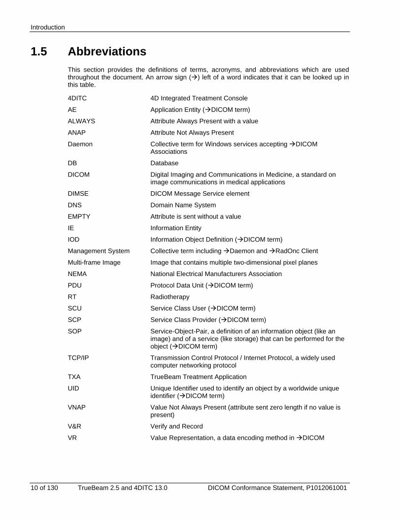
1.5 Abbreviations This section provides the definitions of terms, acronyms, and abbreviations which are used throughout the document. An arrow sign () left of a word indicates that it can be looked up in this table.
4DITC 4D Integrated Treatment Console
AE Application Entity (DICOM term)
ALWAYS Attribute Always Present with a value
ANAP Attribute Not Always Present
Daemon Collective term for Windows services accepting DICOM Associations
DB Database
DICOM Digital Imaging and Communications in Medicine, a standard on image communications in medical applications
DIMSE DICOM Message Service element
DNS Domain Name System
EMPTY Attribute is sent without a value
IE Information Entity
IOD Information Object Definition (DICOM term)
Management System Collective term including Daemon and RadOnc Client
Multi-frame Image Image that contains multiple two-dimensional pixel planes
NEMA National Electrical Manufacturers Association
PDU Protocol Data Unit (DICOM term)
RT Radiotherapy
SCU Service Class User (DICOM term)
SCP Service Class Provider (DICOM term)
SOP Service-Object-Pair, a definition of an information object (like an image) and of a service (like storage) that can be performed for the object (DICOM term)
TCP/IP Transmission Control Protocol / Internet Protocol, a widely used computer networking protocol
TXA TrueBeam Treatment Application
UID Unique Identifier used to identify an object by a worldwide unique identifier (DICOM term)
VNAP Value Not Always Present (attribute sent zero length if no value is present)
V&R Verify and Record
VR Value Representation, a data encoding method in DICOM
Networking
TrueBeam 2.5 and 4DITC 13.0 DICOM Conformance Statement, P1012061001 11 of 130
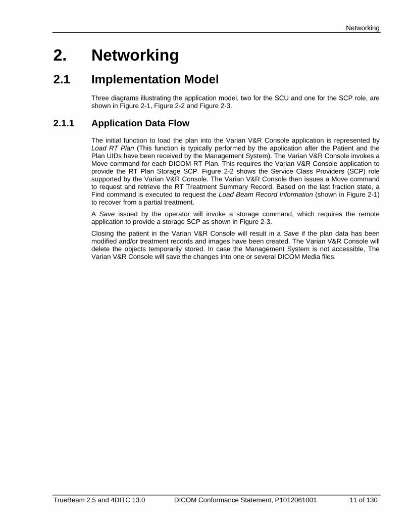
2. Networking 2.1 Implementation Model
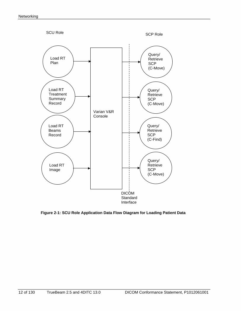
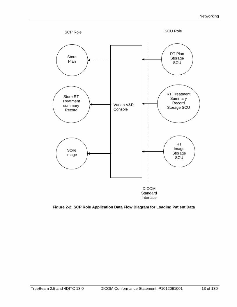
Three diagrams illustrating the application model, two for the SCU and one for the SCP role, are shown in Figure 2-1, Figure 2-2 and Figure 2-3.
2.1.1 Application Data Flow The initial function to load the plan into the Varian V&R Console application is represented by Load RT Plan (This function is typically performed by the application after the Patient and the Plan UIDs have been received by the Management System). The Varian V&R Console invokes a Move command for each DICOM RT Plan. This requires the Varian V&R Console application to provide the RT Plan Storage SCP. Figure 2-2 shows the Service Class Providers (SCP) role supported by the Varian V&R Console. The Varian V&R Console then issues a Move command to request and retrieve the RT Treatment Summary Record. Based on the last fraction state, a Find command is executed to request the Load Beam Record Information (shown in Figure 2-1) to recover from a partial treatment.
A Save issued by the operator will invoke a storage command, which requires the remote application to provide a storage SCP as shown in Figure 2-3.
Closing the patient in the Varian V&R Console will result in a Save if the plan data has been modified and/or treatment records and images have been created. The Varian V&R Console will delete the objects temporarily stored. In case the Management System is not accessible, The Varian V&R Console will save the changes into one or several DICOM Media files.
Networking
12 of 130 TrueBeam 2.5 and 4DITC 13.0 DICOM Conformance Statement, P1012061001
Figure 2-1: SCU Role Application Data Flow Diagram for Loading Patient Data
Varian V&R Console
Query/ Retrieve SCP (C-Move)
Load RT Plan
Load RT Image
Load RT Treatment Summary Record
Load RT Beams Record
DICOM Standard Interface
SCU Role SCP Role
Query/ Retrieve SCP (C-Move)
Query/ Retrieve SCP (C-Move)
Query/ Retrieve SCP (C-Find)
Networking
TrueBeam 2.5 and 4DITC 13.0 DICOM Conformance Statement, P1012061001 13 of 130
Figure 2-2: SCP Role Application Data Flow Diagram for Loading Patient Data
Varian V&R Console
RT Plan Storage
SCU
RT Image
Storage SCU
RT Treatment Summary Record
Storage SCU
Store Plan
Store image
Store RT Treatment summary Record
DICOM Standard Interface
SCP Role SCU Role
Networking
14 of 130 TrueBeam 2.5 and 4DITC 13.0 DICOM Conformance Statement, P1012061001
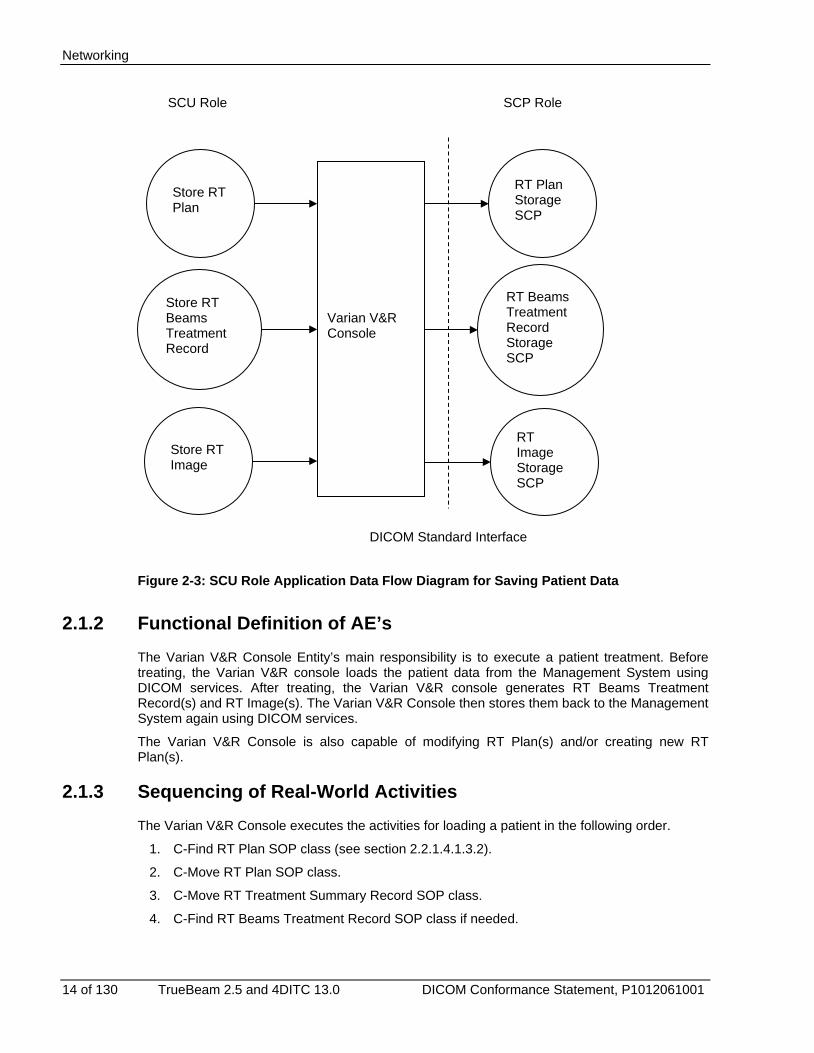
Figure 2-3: SCU Role Application Data Flow Diagram for Saving Patient Data
2.1.2 Functional Definition of AE’s The Varian V&R Console Entity’s main responsibility is to execute a patient treatment. Before treating, the Varian V&R console loads the patient data from the Management System using DICOM services. After treating, the Varian V&R console generates RT Beams Treatment Record(s) and RT Image(s). The Varian V&R Console then stores them back to the Management System again using DICOM services.
The Varian V&R Console is also capable of modifying RT Plan(s) and/or creating new RT Plan(s).
2.1.3 Sequencing of Real-World Activities The Varian V&R Console executes the activities for loading a patient in the following order.
1. C-Find RT Plan SOP class (see section 2.2.1.4.1.3.2).
2. C-Move RT Plan SOP class.
3. C-Move RT Treatment Summary Record SOP class.
4. C-Find RT Beams Treatment Record SOP class if needed.
Varian V&R Console
RT Plan Storage SCP
RT Beams Treatment Record Storage SCP
RT Image Storage SCP
Store RT Plan
Store RT Beams Treatment Record
Store RT Image
DICOM Standard Interface
SCU Role SCP Role

Networking
TrueBeam 2.5 and 4DITC 13.0 DICOM Conformance Statement, P1012061001 15 of 130
Note C-Find RT Beams Treatment Record query is only executed in order to finalize the previous treated fraction.
The 4DITC console also retrieves referenced RT Images. The steps below only apply to the 4DITC console.
5. C-Move RT Image SOP class (for Reference Images if referred in the RT Plan)
6. C-Find RT Image SOP class (for query Portal Images).
7. C-Move RT Image SOP class (for Portal Images if query returned Portal Image Instance UIDs).
The only requirement is to load the RT Plan first before the others. This sequence may be performed for more than one plan at the beginning of a treatment session.
The patient record is saved in the following order to Varian V&R Console:
1. C-Store RT Plan SOP class (executed if a plan is changed in Varian V&R Console).
2. C-Store RT Beams Treatment Record SOP class (executed if a beam was treated).
3. C-Store RT Image SOP class (executed if a Portal Image was acquired) (4DITC only). The only requirement is to save RT Plans first before the RT Beam Records and RT Images. This is because the RT Beams Treatment Record and/or RT Image may refer to the new RT Plan.
2.2 AE Specifications 2.2.1 Varian V&R Console Entity
2.2.1.1 SOP Classes
The Varian V&R Console Entity provides standard conformance to the following DICOM V3.0 SOP classes.
SOP Class Name SCU / SCP Role
SOP Class UID SCU SCP
Verification (Echo) SCU / SCP 1.2.840.10008.1.1 Yes Yes
RT Image Storage SCU / SCP 1.2.840.10008.5.1.4.1.1.481.1 Yes Yes
RT Plan Storage SCU / SCP 1.2.840.10008.5.1.4.1.1.481.5 Yes Yes
RT Treatment Summary Record Storage
SCP 1.2.840.10008.5.1.4.1.1.481.7 No Yes
Study Root Query/Retrieve information model- FIND
SCU 1.2.840.10008.5.1.4.1.2.2.1 Yes No
Study Root Query/Retrieve information model- MOVE
SCU 1.2.840.10008.5.1.4.1.2.2.2 Yes No
RT Beams Treatment Record Storage
SCU 1.2.840.10008.5.1.4.1.1.481.4 Yes No
Table 2-1: Supported SCU/SCP SOP Classes for the Varian V&R Console Entity

Networking
16 of 130 TrueBeam 2.5 and 4DITC 13.0 DICOM Conformance Statement, P1012061001
2.2.1.2 Association Policies
2.2.1.2.1 General
There are a total of three associations. The Varian V&R Console establishes two associations while the Management System establishes one association. The first association established by the Varian V&R Console is to support the C-Move and C-Find services. The second association established by the Varian V&R Console is to support the C-Store service. The association established by the Management System is for storing patient data to the Varian V&R Console.
All of the association supports the C-Echo service to determine whether the association is still alive or not.
A diagram of the associations is in Figure 2-4.
The Varian V&R Console accepts any maximum PDU size for incoming data streams and suggests the size of 65536 for outgoing data streams.
Figure 2-4: Association Used by Varian V&R Consoles
2.2.1.2.2 Number of Associations
Varian V&R consoles support a total of three associations as shown in Figure 2-4. They support having one association for each batch of services at a time.
Varia
n V&
R C
onso
le
Man
agem
ent S
yste
m
C-Find/Move
C-Echo
C-Store RT Plan
C-Store RT Image
C-Store RT Treatment Summary Record
C-Echo Association
C-Store RT Plan
C-Store RT Beams Treatment Record
C-Store RT Image
C-Echo
Networking
TrueBeam 2.5 and 4DITC 13.0 DICOM Conformance Statement, P1012061001 17 of 130
A batch of services refers to the list of services contained in an arrow in Figure 2-4.
2.2.1.2.3 Asynchronous Nature
Asynchronous operation is not supported.
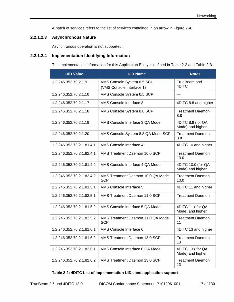
2.2.1.2.4 Implementation Identifying Information
The implementation information for this Application Entity is defined in Table 2-2 and Table 2-3.
UID Value UID Name Notes
1.2.246.352.70.2.1.9 VMS Console System 6.5 SCU (VMS Console Interface 1)
TrueBeam and 4DITC
1.2.246.352.70.2.1.10 VMS Console System 6.5 SCP —
1.2.246.352.70.2.1.17 VMS Console Interface 3 4DITC 8.8 and higher
1.2.246.352.70.2.1.18 VMS Console System 8.8 SCP Treatment Daemon 8.8
1.2.246.352.70.2.1.19 VMS Console Interface 3 QA Mode 4DITC 8.8 (for QA Mode) and higher
1.2.246.352.70.2.1.20 VMS Console System 8.8 QA Mode SCP Treatment Daemon 8.8
1.2.246.352.70.2.1.81.4.1 VMS Console Interface 4 4DITC 10 and higher
1.2.246.352.70.2.1.82.4.1 VMS Treatment Daemon 10.0 SCP Treatment Daemon 10.0
1.2.246.352.70.2.1.81.4.2 VMS Console Interface 4 QA Mode 4DITC 10.0 (for QA Mode) and higher
1.2.246.352.70.2.1.82.4.2 VMS Treatment Daemon 10.0 QA Mode SCP
Treatment Daemon 10.0
1.2.246.352.70.2.1.81.5.1 VMS Console Interface 5 4DITC 11 and higher
1.2.246.352.70.2.1.82.5.1 VMS Treatment Daemon 11.0 SCP Treatment Daemon 11
1.2.246.352.70.2.1.81.5.2 VMS Console Interface 5 QA Mode 4DITC 11 ( for QA Mode) and higher
1.2.246.352.70.2.1.82.5.2 VMS Treatment Daemon 11.0 QA Mode SCP
Treatment Daemon 11
1.2.246.352.70.2.1.81.6.1 VMS Console Interface 6 4DITC 13 and higher
1.2.246.352.70.2.1.81.6.2 VMS Treatment Daemon 13.0 SCP Treatment Daemon 13
1.2.246.352.70.2.1.82.6.1 VMS Console Interface 6 QA Mode 4DITC 13 ( for QA Mode) and higher
1.2.246.352.70.2.1.82.6.2 VMS Treatment Daemon 13.0 SCP Treatment Daemon 13
Table 2-2: 4DITC List of implementation UIDs and application support

Networking
18 of 130 TrueBeam 2.5 and 4DITC 13.0 DICOM Conformance Statement, P1012061001
UID Value UID Name Notes
1.2.246.352.70.2.1.9 VMS Console System 6.5 SCU (VMS Console Interface 1)
—
1.2.246.352.70.2.1.10 VMS Console System 6.5 SCP —
1.2.246.352.70.2.1.17 VMS Console Interface 3 —
1.2.246.352.70.2.1.18 VMS Console System 8.8 SCP —
1.2.246.352.70.2.1.19 VMS Console Interface 3 QA Mode —
1.2.246.352.70.2.1.20 VMS Console System 8.8 QA Mode SCP —
Table 2-3: TrueBeam TXA list of implementation UIDs supported and used
2.2.1.3 Association Initiation Policy
The Varian V&R Console Entity will initiate one association for all Query/Retrieve Services (Q/R SCU) that contains the C-Find and the C-Move service. When the user starts up the Varian V&R Console and clicks on “Open Patient”, it initiates an association for all Query/Retrieve Services for the first time.
The Varian V&R Console Entity will initiate one association for all Storage Services where it acts as a user (Storage SCU).
The Management System will initiate one association for all C-Store services used for sending all patient data. In this association, Varian V&R Console acts as a provider (Storage SCP).
The Echo/Verification service is used prior to any other DICOM service to verify whether an established association exists.
2.2.1.3.1 Save Images (4DITC only)
When the user clicks “Save Images” ("Save images" is applicable to 4DITC only) or “Close Patient”, 4DITC checks if an association already exists for all Storage Services. If an association does not exist for all Storage Services, 4DITC initiates an association for all Storage Services. Otherwise, 4DITC uses the existing association.
2.2.1.4 Storage SCU
2.2.1.4.1.1 Associated Real-World Activity
The C-Store service is used by 4DITC to store patient data into the Management System. This service gets executed whenever the operator selects ‘Close Patient’ or ‘Save Image’.

Networking
TrueBeam 2.5 and 4DITC 13.0 DICOM Conformance Statement, P1012061001 19 of 130
2.2.1.4.1.2 Presentation Context Table
Presentation Context Table
Abstract Syntax Transfer Syntax Role Extended Negotiation
TXA 2.5
4DITC 13.0
Name UID Name UID
RT Plan Storage
1.2.840.10008.5.1.4.1.1.481.5
DICOM Implicit VR Little Endian
1.2.840.10008.1.2
SCU None Yes Yes
RT Beams Treatment Record Storage
1.2.840.10008.5.1.4.1.1.481.4
DICOM Implicit VR Little Endian
1.2.840.10008.1.2
SCU None Yes Yes
RT Image Storage
1.2.840.10008.5.1.4.1.1.481.1
DICOM Implicit VR Little Endian
1.2.840.10008.1.2
SCU None Yes Yes
Table 2-4: Proposed Presentation Contexts for Storage SCU
2.2.1.4.1.3 SOP Specific Conformance
2.2.1.4.1.3.1 SOP Specific Conformance for All Storage SOP Classes
After a successful C-STORE operation, the Varian V&R Console does not display any information to the user but returns to its normal state. If the C-STORE operation results with a warning or an error, the Varian V&R console displays the appropriate warning or error message to the operator.
2.2.1.4.1.3.2 SOP Specific Conformance for the RT Plan Storage SOP Class
4DITC (only) with implementation UID ‘Varian Console Interface 4’ and ‘Varian Console Interface 4 QA Mode’ or later
These tags are in addition to conformance rules applied for lower version of implementation UIDs supported in older version of Varian V&R Console.
Varian V&R Consoles use the following tags from ‘Patient Setup Sequence (300A,0180):
• Table Top Vertical Setup Displacement (300A,01d2).
• Table Top Longitudinal Setup Displacement (300A,01d4).
• Table Top Lateral Setup Displacement (300A,01d6).
Also, when SOP object has at least one table top setup displacement defined, 4DITC (only) considers zero value for remaining undefined table top setup displacements.
Note Table top displacement values listed above are not supported by TrueBeam v2.5
Varian V&R Consoles communicating on implementation UID “Varian Console Interface 3” and “Varian Console Interface 3 QA Mode” or later:
Networking
20 of 130 TrueBeam 2.5 and 4DITC 13.0 DICOM Conformance Statement, P1012061001
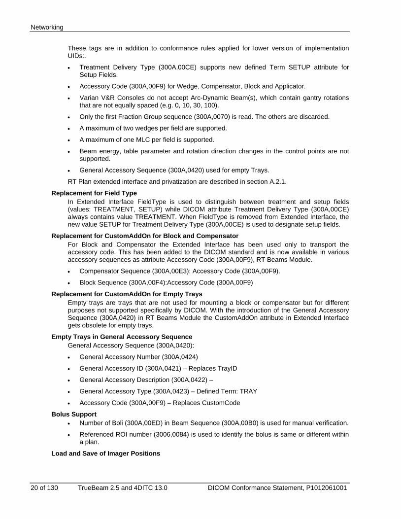
These tags are in addition to conformance rules applied for lower version of implementation UIDs:.
• Treatment Delivery Type (300A,00CE) supports new defined Term SETUP attribute for Setup Fields.
• Accessory Code (300A,00F9) for Wedge, Compensator, Block and Applicator.
• Varian V&R Consoles do not accept Arc-Dynamic Beam(s), which contain gantry rotations that are not equally spaced (e.g. 0, 10, 30, 100).
• Only the first Fraction Group sequence (300A,0070) is read. The others are discarded.
• A maximum of two wedges per field are supported.
• A maximum of one MLC per field is supported.
• Beam energy, table parameter and rotation direction changes in the control points are not supported.
• General Accessory Sequence (300A,0420) used for empty Trays.
RT Plan extended interface and privatization are described in section A.2.1.
Replacement for Field Type In Extended Interface FieldType is used to distinguish between treatment and setup fields (values: TREATMENT, SETUP) while DICOM attribute Treatment Delivery Type (300A,00CE) always contains value TREATMENT. When FieldType is removed from Extended Interface, the new value SETUP for Treatment Delivery Type (300A,00CE) is used to designate setup fields.
Replacement for CustomAddOn for Block and Compensator For Block and Compensator the Extended Interface has been used only to transport the accessory code. This has been added to the DICOM standard and is now available in various accessory sequences as attribute Accessory Code (300A,00F9), RT Beams Module.
• Compensator Sequence (300A,00E3): Accessory Code (300A,00F9).
• Block Sequence (300A,00F4):Accessory Code (300A,00F9)
Replacement for CustomAddOn for Empty Trays Empty trays are trays that are not used for mounting a block or compensator but for different purposes not supported specifically by DICOM. With the introduction of the General Accessory Sequence (300A,0420) in RT Beams Module the CustomAddOn attribute in Extended Interface gets obsolete for empty trays.
Empty Trays in General Accessory Sequence General Accessory Sequence (300A,0420):
• General Accessory Number (300A,0424)
• General Accessory ID (300A,0421) – Replaces TrayID
• General Accessory Description (300A,0422) –
• General Accessory Type (300A,0423) – Defined Term: TRAY
• Accessory Code (300A,00F9) – Replaces CustomCode
Bolus Support • Number of Boli (300A,00ED) in Beam Sequence (300A,00B0) is used for manual verification.
• Referenced ROI number (3006,0084) is used to identify the bolus is same or different within a plan.
Load and Save of Imager Positions
Networking
TrueBeam 2.5 and 4DITC 13.0 DICOM Conformance Statement, P1012061001 21 of 130
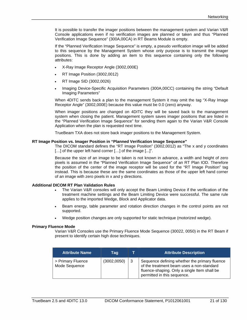
It is possible to transfer the imager positions between the management system and Varian V&R Console applications even if no verification images are planned or taken and thus “Planned Verification Image Sequence” (300A,00CA) in RT Beams Module is empty.
If the “Planned Verification Image Sequence” is empty, a pseudo verification image will be added to this sequence by the Management System whose only purpose is to transmit the imager positions. This is done by adding an item to this sequence containing only the following attributes:
• X-Ray Image Receptor Angle (3002,000E)
• RT Image Position (3002,0012)
• RT Image SID (3002,0026)
• Imaging Device-Specific Acquisition Parameters (300A,00CC) containing the string “Default Imaging Parameters”
When 4DITC sends back a plan to the management System it may omit the tag “X-Ray Image Receptor Angle” (3002,000E) because this value must be 0.0 (zero) anyway.
When imager positions are changed on 4DITC they will be saved back to the management system when closing the patient. Management system saves imager positions that are listed in the “Planned Verification Image Sequence” for sending them again to the Varian V&R Console Application when the plan is requested next time.
TrueBeam TXA does not store back imager positions to the Management System.
RT Image Position vs. Imager Position in “Planned Verification Image Sequence” The DICOM standard defines the “RT Image Position” (3002,0012) as “The x and y coordinates […] of the upper left hand corner […] of the image [...]”.
Because the size of an image to be taken is not known in advance, a width and height of zero pixels is assumed in the “Planned Verification Image Sequence” of an RT Plan IOD. Therefore the position of the center of the image receptor will be used for the “RT Image Position” tag instead. This is because these are the same coordinates as those of the upper left hand corner of an image with zero pixels in x and y directions.
Additional DICOM RT Plan Validation Rules • The Varian V&R consoles will only accept the Beam Limiting Device if the verification of the
treatment machine settings and the Beam Limiting Device were successful. The same rule applies to the imported Wedge, Block and Applicator data.
• Beam energy, table parameter and rotation direction changes in the control points are not supported.
• Wedge position changes are only supported for static technique (motorized wedge).
Primary Fluence Mode Varian V&R Consoles use the Primary Fluence Mode Sequence (30022, 0050) in the RT Beam if present to identify certain high dose techniques.
Attribute Name Tag T Attribute Description
> Primary Fluence Mode Sequence
(3002,0050) 3 Sequence defining whether the primary fluence of the treatment beam uses a non-standard fluence-shaping. Only a single Item shall be permitted in this sequence.

Networking
22 of 130 TrueBeam 2.5 and 4DITC 13.0 DICOM Conformance Statement, P1012061001
Attribute Name Tag T Attribute Description
>> Fluence Mode (3002,0051) 1 Describes whether the fluence shaping is the standard mode for the beam or an alternate. Enumerated Values: STANDARD = Uses standard fluence-shaping NON_STANDARD = Uses a non-standard fluence-shaping mode
>> Fluence Mode ID (3002,0052) 1C Identifier for the specific fluence-shaping mode. Required if Fluence Mode (3002, 0051) has value NON_STANDARD. The following mode IDs are supported SRS (4DITC only) FFF
Table 2-5: Primary Fluence Mode Sequence support in Varian V&R Consoles
TrueBeam TXA The supported combination of High dose technique, Dose rate, Primary Fluence Mode and energy are listed in 6 below.
Nominal Beam Energy
(MV/MeV) (300A,0114)
Dose Rate Set MU/Min
(300A,0115)
Primary Fluence Mode
(3002,0051)
High-Dose Technique
Type
(300A,00C7)
2.5x 60 STANDARD NON_STANDARD
Normal TBI HDR SRS
4x 5, 10, 15, 20, 30, 40, 50, 100, 150, 200, 250
STANDARD NON_STANDARD
Normal TBI HDR SRS
6x 5, 10, 15, 20, 40, 60, 80, 100, 200, 300, 400, 500, 600
STANDARD NON_STANDARD
Normal TBI HDR SRS
6x FFF 400, 600, 800, 1000, 1200, 1400 STANDARD NON_STANDARD
Normal TBI HDR SRS
8x 5, 10, 15, 20, 40, 60, 80, 100, 200, 300, 400, 500, 600
STANDARD NON_STANDARD
Normal TBI HDR SRS

Networking
TrueBeam 2.5 and 4DITC 13.0 DICOM Conformance Statement, P1012061001 23 of 130
Nominal Beam Energy
(MV/MeV) (300A,0114)
Dose Rate Set MU/Min (300A,0115)
Primary Fluence Mode
(3002,0051)
High-Dose Technique
Type
(300A,00C7)
10x 5, 10, 15, 20, 40, 60, 80, 100, 200, 300, 400, 500, 600
STANDARD NON_STANDARD
Normal TBI HDR SRS
10x FFF 400, 600, 800, 1000, 1200, 1400, 2400
STANDARD NON_STANDARD
Normal TBI HDR SRS
15x 20, 40, 60, 80, 100, 200, 300, 400, 500, 600
STANDARD NON_STANDARD
Normal TBI HDR SRS
18x 20, 40, 60, 80, 100, 200, 300, 400, 500, 600
STANDARD NON_STANDARD
Normal TBI HDR SRS
20x 20, 40, 60, 80, 100, 200, 300, 400, 500, 600
STANDARD NON_STANDARD
Normal TBI HDR SRS
4e 100, 200, 300, 400, 500, 600, 700, 800, 900, 1000
STANDARD NON_STANDARD
Normal TBI HDR SRS
6e 100, 200, 300, 400, 500, 600, 700, 800, 900, 1000 2500 for HDR
STANDARD NON_STANDARD
Normal TBI HDR SRS
9e 100, 200, 300, 400, 500, 600, 700, 800, 900, 1000 2500 for HDR
STANDARD NON_STANDARD
Normal TBI HDR SRS
12e 100, 200, 300, 400, 500, 600, 700, 800, 900, 1000
STANDARD NON_STANDARD
Normal TBI HDR SRS
Networking
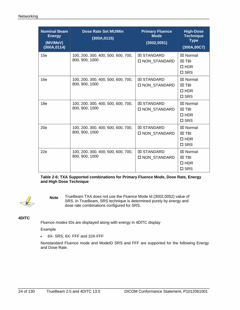
24 of 130 TrueBeam 2.5 and 4DITC 13.0 DICOM Conformance Statement, P1012061001
Nominal Beam Energy
(MV/MeV) (300A,0114)
Dose Rate Set MU/Min (300A,0115)
Primary Fluence Mode
(3002,0051)
High-Dose Technique
Type
(300A,00C7)
15e 100, 200, 300, 400, 500, 600, 700, 800, 900, 1000
STANDARD NON_STANDARD
Normal TBI HDR SRS
16e 100, 200, 300, 400, 500, 600, 700, 800, 900, 1000
STANDARD NON_STANDARD
Normal TBI HDR SRS
18e 100, 200, 300, 400, 500, 600, 700, 800, 900, 1000
STANDARD NON_STANDARD
Normal TBI HDR SRS
20e 100, 200, 300, 400, 500, 600, 700, 800, 900, 1000
STANDARD NON_STANDARD
Normal TBI HDR SRS
22e 100, 200, 300, 400, 500, 600, 700, 800, 900, 1000
STANDARD NON_STANDARD
Normal TBI HDR SRS
Table 2-6: TXA Supported combinations for Primary Fluence Mode, Dose Rate, Energy and High Dose Technique
Note TrueBeam TXA does not use the Fluence Mode Id (3002,0052) value of SRS. In TrueBeam, SRS technique is determined purely by energy and dose rate combinations configured for SRS.
4DITC Fluence modes IDs are displayed along with energy in 4DITC display
Example
• 6X- SRS, 6X- FFF and 10X-FFF
Nonstandard Fluence mode and ModeID SRS and FFF are supported for the following Energy and Dose Rate.
Networking
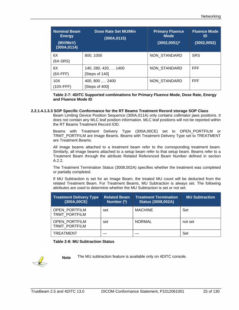
TrueBeam 2.5 and 4DITC 13.0 DICOM Conformance Statement, P1012061001 25 of 130
Nominal Beam Energy
(MV/MeV) (300A,0114)
Dose Rate Set MU/Min (300A,0115)
Primary Fluence Mode
(3002,0051)*
Fluence Mode ID
(3002,0052)
6X (6X-SRS)
800, 1000 NON_STANDARD SRS
6X (6X-FFF)
140, 280, 420, … 1400 [Steps of 140]
NON_STANDARD FFF
10X (10X-FFF)
400, 800 ,… 2400 [Steps of 400]
NON_STANDARD FFF
Table 2-7: 4DITC Supported combinations for Primary Fluence Mode, Dose Rate, Energy and Fluence Mode ID
2.2.1.4.1.3.3 SOP Specific Conformance for the RT Beams Treatment Record storage SOP Class Beam Limiting Device Position Sequence (300A,011A) only contains collimator jaws positions. It does not contain any MLC leaf position information. MLC leaf positions will not be reported within the RT Beams Treatment Record IOD.
Beams with Treatment Delivery Type (300A,00CE) set to OPEN_PORTFILM or TRMT_PORTFILM are Image Beams. Beams with Treatment Delivery Type set to TREATMENT are Treatment Beams.
All image beams attached to a treatment beam refer to the corresponding treatment beam. Similarly, all image beams attached to a setup beam refer to that setup beam. Beams refer to a Treatment Beam through the attribute Related Referenced Beam Number defined in section A.2.2.
The Treatment Termination Status (3008,002A) specifies whether the treatment was completed or partially completed.
If MU Subtraction is set for an Image Beam, the treated MU count will be deducted from the related Treatment Beam. For Treatment Beams, MU Subtraction is always set. The following attributes are used to determine whether the MU Subtraction is set or not set:
Treatment Delivery Type (300A,00CE)
Related Beam Number (*)
Treatment Termination Status (3008,002A)
MU Subtraction
OPEN_PORTFILM TRMT_PORTFILM
set MACHINE Set
OPEN_PORTFILM TRMT_PORTFILM
set NORMAL not set
TREATMENT — — Set
Table 2-8: MU Subtraction Status
Note The MU subtraction feature is available only on 4DITC console.
Networking
26 of 130 TrueBeam 2.5 and 4DITC 13.0 DICOM Conformance Statement, P1012061001
(*) Related Beam Number is a private tag added to the RT Beams Session Record module (see section A.2.2).
RT Beams Treatment Record Extended Interface and Privatizations are described in section 4.
The following SOP specific conformance rules apply to Varian V&R Consoles with implementation UID ‘Varian Console Interface 4’ or later.
• Varian V&R Consoles support Treatment notes to be saved as part of RT Beams Treatment Record when patient session is closed. To store Treatment Notes in RT Beams Treatment Record, standard DICOM tag “Beam Description (300A,00C3) is used.
• Actual SSD is saved to RT Beams Treatment Record when patient session is closed. To store SSD in RT Beams Treatment Record, the Dicom tag “Source to Surface Distance (300A,0130)” is used.
2.2.1.4.1.3.4 SOP specific conformance for the RT Image Storage SOP class
The 4DITC Entity only stores images with the Image Type (0008,0008) set to PORTAL. TrueBeam TXA does not support RT Image storage.
2.2.1.4.2 Query/Retrieve SCU
2.2.1.4.2.1 Associated Real-World Activity
Varian V&R Consoles use the Query/Retrieve information model MOVE for retrieving patient data from the Management System. After a successful query, the Management System sends the requested data with the C-Store service.
Varian V&R Consoles uses the Query/Retrieve information model FIND for gathering information from the Management System. In order to determine whether a Beam was partially treated or completed, Varian V&R Consoles queries for several attributes in the RT Beams Treatment Record stored in the management.
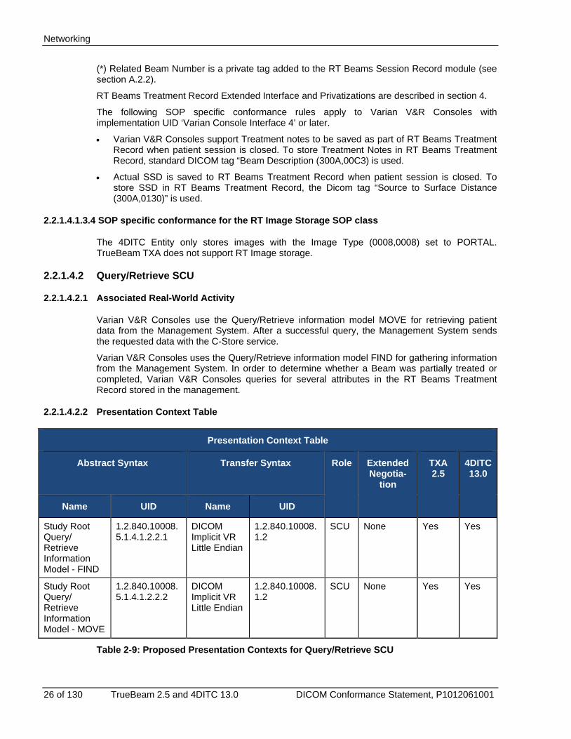
2.2.1.4.2.2 Presentation Context Table
Presentation Context Table
Abstract Syntax Transfer Syntax Role Extended Negotia-
tion
TXA 2.5
4DITC 13.0
Name UID Name UID
Study Root Query/ Retrieve Information Model - FIND
1.2.840.10008.5.1.4.1.2.2.1
DICOM Implicit VR Little Endian
1.2.840.10008.1.2
SCU None Yes Yes
Study Root Query/ Retrieve Information Model - MOVE
1.2.840.10008.5.1.4.1.2.2.2
DICOM Implicit VR Little Endian
1.2.840.10008.1.2
SCU None Yes Yes
Table 2-9: Proposed Presentation Contexts for Query/Retrieve SCU
Networking
TrueBeam 2.5 and 4DITC 13.0 DICOM Conformance Statement, P1012061001 27 of 130
2.2.1.4.2.3 SOP Specific Conformance
The following Query/Retrieve SOP classes are used by Varian V&R Consoles as a Service Class User (SCU):
• C-Move RT Plan
• C-Move RT Treatment Summary Record
• C-Move RT Image
• C-Find RT Beams Treatment Record
• C-Find RT Plan
• C-Find RT Image (4DITC only)
2.2.1.4.2.3.1 SOP specific Conformance for the C-Move SOP Classes
For all C-Move SOP classes, the query key is always the SOP Instance UID of the particular DICOM IOD that the Varian V&R Console requests. There are no other matching criteria’s for the C-Move key. All keys used for the C-Move service are defined in section B 1.1.
The C-Move service requires the Varian V&R Console to be an SCP of the C-Store service for the same DICOM IOD. For example whenever the Varian V&R Console is a SCU of C-Move RT Plan it implies that the V&R Console is a SCP of C-Store RT Plan (see Figure 2-1).
2.2.1.4.2.3.2 SOP specific Conformance for the C-Find RT Beams Treatment Record SOP Class
The C-Find RT Beams Treatment Record SOP class will be used for calculating the remaining MU. The remaining monitor units are calculated with the Beam Meterset (300A,0086) in the RT Fraction Scheme module (provided from the Plan IOD) minus the Delivered Primary Meterset (3008,0036) (provided from the Beam Record Information) -see Table B-7). If the monitor units were overridden, the Beam Record Information contains the overridden value in the Specified Meterset (3008,0042). In this case, the overridden Specified Meterset (3008,0042) is used instead of the Beam Meterset (300A,0086) to calculate the remaining monitor units.
• Calculation of Remaining MU when monitor units are not overriden:
• Remaining MU = Beam Meterset (300A,0086) – Delivered Primary Meterset (3008,0036)
• Calculation of Remaining MU when monitor units are overriden:
• Remaining MU = Specified Meterset (3008,0042) – Delivered Primary Meterset (3008,0036)
The Treatment Record key contains the matching criteria for the RT Beams Treatment Record. Whenever the key matches the particular RT Beams Treatment Record, the attributes defined in Table B-7 (SCP column) gets filled in. Note that the Treatment Session Beam Sequence may contain one or more item. It is up to the Management System to decide whether for each Treatment Session Beam one Treatment Record key gets sent or if all Treatment Session Beams are sent within one Treatment Record key.
Only the last treated fraction is the fraction of interest.
2.2.1.4.2.3.3 SOP specific conformance for the C-Find RT Plan SOP class
Plans may be loaded into 4DITC without having them scheduled for the current session. Therefore 4DITC has to know how many treatment plans a patient has. This information gets retrieved with the C-Find RT Plan SOP Class. The Plan key contains the matching criteria and the placeholder for all attributes. The Plan key is defined in Table B-6. The SOP Instance UID defined in the Plan key is the Plan Instance UID which will be used to load an unscheduled Plan in 4DITC (only).
Networking
28 of 130 TrueBeam 2.5 and 4DITC 13.0 DICOM Conformance Statement, P1012061001
Note The unscheduled plan load feature is available only on 4DITC console.
2.2.1.4.2.3.4 SOP specific conformance for the C-Find RT Image SOP class
Since Portal Images are not referenced within the RT Plan, 4DITC (only) queries the Portal Images from the Management System with the C-Find RT Image service SOP class. The Image key is defined in Table B-5. The Referenced SOP Instance UID (i.e. the Plan Instance UID) and the Referenced Beam Number uniquely identifies the Beam, which 4DITC needs to query the Portal Images from. 4DITC uses the SOP Instance UID (i.e. the RT Image Instance UID) to retrieve previous acquired Portal Image. The C-Find confirmation returns as many Image keys as Portal Images stored in the Management System for that particular beam.
Note Portal Images are not retrieved by the TrueBeam TXA console.
2.2.2 Association Acceptance Policy The Varian V&R Console Entity accepts association requests for the supported service classes shown in Figure 2-2. Varian V&R Consoles accept only one Management System Application Entity for the possible association.
2.2.2.1 Storage SCP
2.2.2.1.1 Associated Real-World Activity
The patient data is sent from the Management System to Varian V&R Console using the C-Store service. This is the only service that Varian V&R Consoles support as an SCP.
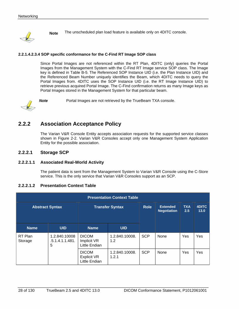
2.2.2.1.2 Presentation Context Table
Presentation Context Table
Abstract Syntax Transfer Syntax Role Extended Negotiation
TXA 2.5
4DITC 13.0
Name UID Name UID
RT Plan Storage
1.2.840.10008.5.1.4.1.1.481.5
DICOM Implicit VR Little Endian
1.2.840.10008.1.2
SCP None Yes Yes
DICOM Explicit VR Little Endian
1.2.840.10008.1.2.1
SCP None Yes Yes
Networking
TrueBeam 2.5 and 4DITC 13.0 DICOM Conformance Statement, P1012061001 29 of 130
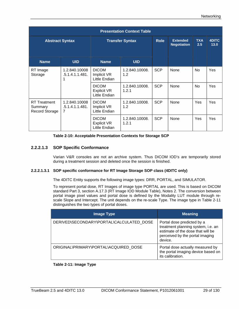
Presentation Context Table
Abstract Syntax Transfer Syntax Role Extended Negotiation
TXA 2.5
4DITC 13.0
Name UID Name UID
RT Image Storage
1.2.840.10008.5.1.4.1.1.481.1
DICOM Implicit VR Little Endian
1.2.840.10008.1.2
SCP None No Yes
DICOM Explicit VR Little Endian
1.2.840.10008.1.2.1
SCP None No Yes
RT Treatment Summary Record Storage
1.2.840.10008.5.1.4.1.1.481.7
DICOM Implicit VR Little Endian
1.2.840.10008.1.2
SCP None Yes Yes
DICOM Explicit VR Little Endian
1.2.840.10008.1.2.1
SCP None Yes Yes
Table 2-10: Acceptable Presentation Contexts for Storage SCP
2.2.2.1.3 SOP Specific Conformance
Varian V&R consoles are not an archive system. Thus DICOM IOD’s are temporarily stored during a treatment session and deleted once the session is finished.
2.2.2.1.3.1 SOP specific conformance for RT Image Storage SOP class (4DITC only)
The 4DITC Entity supports the following image types: DRR, PORTAL, and SIMULATOR.
To represent portal dose, RT Images of image type PORTAL are used. This is based on DICOM standard Part 3, section A.17.3 (RT Image IOD Module Table), Notes 2. The conversion between portal image pixel values and portal dose is defined by the Modality LUT module through re-scale Slope and Intercept. The unit depends on the re-scale Type. The image type in Table 2-11 distinguishes the two types of portal doses.
Image Type Meaning
DERIVED\SECONDARY\PORTAL\CALCULATED_DOSE Portal dose predicted by a treatment planning system, i.e. an estimate of the dose that will be perceived by the portal imaging device.
ORIGINAL\PRIMARY\PORTAL\ACQUIRED_DOSE Portal dose actually measured by the portal imaging device based on its calibration.
Table 2-11: Image Type
Networking
30 of 130 TrueBeam 2.5 and 4DITC 13.0 DICOM Conformance Statement, P1012061001
2.2.2.1.3.2 RT Image Geometrical Values (4DITC only)
RT Images (used as reference images) require a sufficient amount of geometrical parameters that will define the position of RT Images with respect to the machine. The following parameters are required for proper operation of image verification applications associated with 4DITC:
• X-Ray Image Receptor Translation (3002,000D)
Value must be present.
• X-Ray Image Receptor Angle (3002,000E)
Value must be present.
Note In the current release, only 0 is supported. Providing this value will ensure safe interpretation.
• RT Image Position (3002,0012)
It is recommended to have this value defined. If the value is not defined, the application will assume that the image was centered on the X-Ray Image Receptor System.
• Radiation Machine SAD (3002,0022) or RT Image SID (3002,0026)
At least one of the two values must be present.
• Image Plane Pixel Spacing (3002,0011)
Value must be present.
• Gantry Angle (300A,011E)
Value must be present. This value shall represent the angle (in IEC GANTRY system coordinates) where the physical or virtual (in case of DRR) source of radiation is located.
Note When kV images are used as Reference Images, this value describes the projection geometry. Therefore, this value may not coincide with the Gantry Hardware Readout of the linear accelerator since the kV Image radiation source may be on a different position than the linear accelerator’ target focus.
• RT Orientation (3002,0010)
In the future, it is recommended to have this value defined for images that have the RT Image Plane set to NORMAL (this value is required for NON-NORMAL images). This is because the DICOM standard does not unambiguously define the position of the RT Image pixel area in the IEC Image Receptor system when this value is missing. If this value is not provided, the application assumes that the value is (1,0,0,0,- 1,0).
2.2.2.1.3.3 SOP specific conformance for the RT Treatment Summary Record SOP class
RT Treatment Summary Record IOD contains additional private tags defined in section A.2.3.
2.2.2.2 Presentation Context Acceptance Criterion
The Varian V&R Console Entity will accept the presentation contexts listed in Table 2-4: Proposed Presentation Contexts for Query/Retrieve SCU.
Networking
TrueBeam 2.5 and 4DITC 13.0 DICOM Conformance Statement, P1012061001 31 of 130
2.2.2.3 Transfer Syntax Selection Policies
Varian V&R Consoles accept both Implicit VR Little Endian and Explicit VR Little Endian as shown in Table 2-4. Varian V&R Consoles do not prefer one presentation context over the other.
2.3 Communication profiles 2.3.1 Supported communications stacks
The Varian V&R Console Entity provides DICOM V3.0 TCP/IP Network Communication Support as defined in PS 3.8 (part 8 of the DICOM V3.0 standard).
2.3.1.1 TCP/IP stack
The Varian V&R Console Entity uses the TCP/IP stack of Microsoft Windows Operating Systems (Winsock).
2.3.1.1.1 Physical media support
The Varian V&R Console Entity can run on any physical network media that is supported by the underlying hardware and operating system. These include, but are not limited to: thin, thick, and twisted-pair Ethernet, token ring network and FDDI.
2.4 Configuration 2.4.1 4DITC DICOM Configuration
4DITC is configured through the 4DITC Administration application.
2.4.1.1 AE Title/Presentation Address Mapping
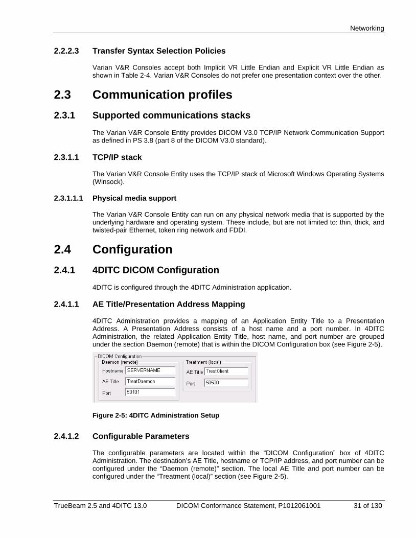
4DITC Administration provides a mapping of an Application Entity Title to a Presentation Address. A Presentation Address consists of a host name and a port number. In 4DITC Administration, the related Application Entity Title, host name, and port number are grouped under the section Daemon (remote) that is within the DICOM Configuration box (see Figure 2-5).
Figure 2-5: 4DITC Administration Setup
2.4.1.2 Configurable Parameters
The configurable parameters are located within the “DICOM Configuration” box of 4DITC Administration. The destination’s AE Title, hostname or TCP/IP address, and port number can be configured under the “Daemon (remote)” section. The local AE Title and port number can be configured under the “Treatment (local)” section (see Figure 2-5).
Networking
32 of 130 TrueBeam 2.5 and 4DITC 13.0 DICOM Conformance Statement, P1012061001
Note In case warnings or errors are encountered after configuration, there are logs available to assist in determining the cause of the problem. 4DITC Administration has a “4D Console Application Configuration” section with a Log Level setting. When this Log Level is set to “Detailed” 4DITC writes more information to the log that will help in debugging the problem.
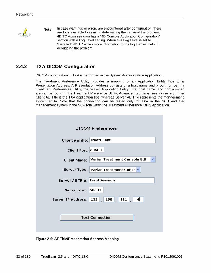
2.4.2 TXA DICOM Configuration DICOM configuration in TXA is performed in the System Administration Application.
The Treatment Preference Utility provides a mapping of an Application Entity Title to a Presentation Address. A Presentation Address consists of a host name and a port number. In Treatment Preferences Utility, the related Application Entity Title, host name, and port number are can be found in the Treatment Preference Utility, Advanced tab page (see Figure 2-6). The Client AE Title is the TXA application title, whereas Server AE Title represents the management system entity. Note that the connection can be tested only for TXA in the SCU and the management system in the SCP role within the Treatment Preference Utility Application.
Figure 2-6: AE Title/Presentation Address Mapping
Media Interchange
TrueBeam 2.5 and 4DITC 13.0 DICOM Conformance Statement, P1012061001 33 of 130
3. Media Interchange The Varian V&R console Application Entity does not support Media Interchange.
Support of Extended Character Sets
34 of 130 TrueBeam 2.5 and 4DITC 13.0 DICOM Conformance Statement, P1012061001
4. Support of Extended Character Sets No dedicated support for Character Sets beyond the Default Repertoire is available. However, text fields containing characters not in the Default Character Repertoire when importing an instance will appear unchanged when re-exporting the same instance again
The following character set encodings are supported.
• Code Page 1252(Western Europe) or CP-1252
• Code Page 936 (Simplified Chinese)
• Code Page 932 (Japanese)
4DITC (only) with implementation UID ‘Varian Console Interface 6’ or later supports:
• UTF-8
Correct display of characters not in the Default Character Repertoire depends on available/configured operating system support.

Security
TrueBeam 2.5 and 4DITC 13.0 DICOM Conformance Statement, P1012061001 35 of 130
5. Security 5.1 Security Profiles
No Security Profiles are supported.
5.2 Association Level Security The V&R console checks the following values when determining whether to accept Association Open Requests:
• Called AE Title
5.3 Application Level Security Local administrative rights are required for installing Varian V&R consoles.
Security
36 of 130 TrueBeam 2.5 and 4DITC 13.0 DICOM Conformance Statement, P1012061001
(This page is intentionally left blank.)
Specialization
TrueBeam 2.5 and 4DITC 13.0 DICOM Conformance Statement, P1012061001 37 of 130
Appendix A Specialization A.1 IOD Contents A.1.1 Created SOP Instances
IODs created by Varian V&R Console Entities are listed in Appendix C along with supported modules and its attributes.
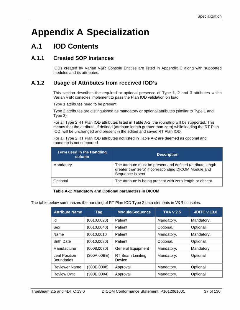
A.1.2 Usage of Attributes from received IOD’s This section describes the required or optional presence of Type 1, 2 and 3 attributes which Varian V&R consoles implement to pass the Plan IOD validation on load:
Type 1 attributes need to be present.
Type 2 attributes are distinguished as mandatory or optional attributes (similar to Type 1 and Type 3)
For all Type 2 RT Plan IOD attributes listed in Table A-2, the roundtrip will be supported. This means that the attribute, if defined (attribute length greater than zero) while loading the RT Plan IOD, will be unchanged and present in the edited and saved RT Plan IOD.
For all Type 2 RT Plan IOD attributes not listed in Table A-2 are deemed as optional and roundtrip is not supported.
Term used in the Handling column Description
Mandatory The attribute must be present and defined (attribute length greater than zero) if corresponding DICOM Module and Sequence is sent.
Optional The attribute is being present with zero length or absent.
Table A-1: Mandatory and Optional parameters in DICOM
The table below summarizes the handling of RT Plan IOD Type 2 data elements in V&R consoles.
Attribute Name Tag Module/Sequence TXA v 2.5 4DITC v 13.0
Id (0010,0020) Patient Mandatory. Mandatory.
Sex (0010,0040) Patient Optional. Optional.
Name (0010,0010 Patient Mandatory. Mandatory.
Birth Date (0010,0030) Patient Optional. Optional.
Manufacturer (0008,0070) General Equipment Mandatory. Mandatory
Leaf Position Boundaries
(300A,00BE) RT Beam Limiting Device
Mandatory. Optional
Reviewer Name (300E,0008) Approval Mandatory. Optional
Review Date (300E,0004) Approval Mandatory. Optional
Specialization
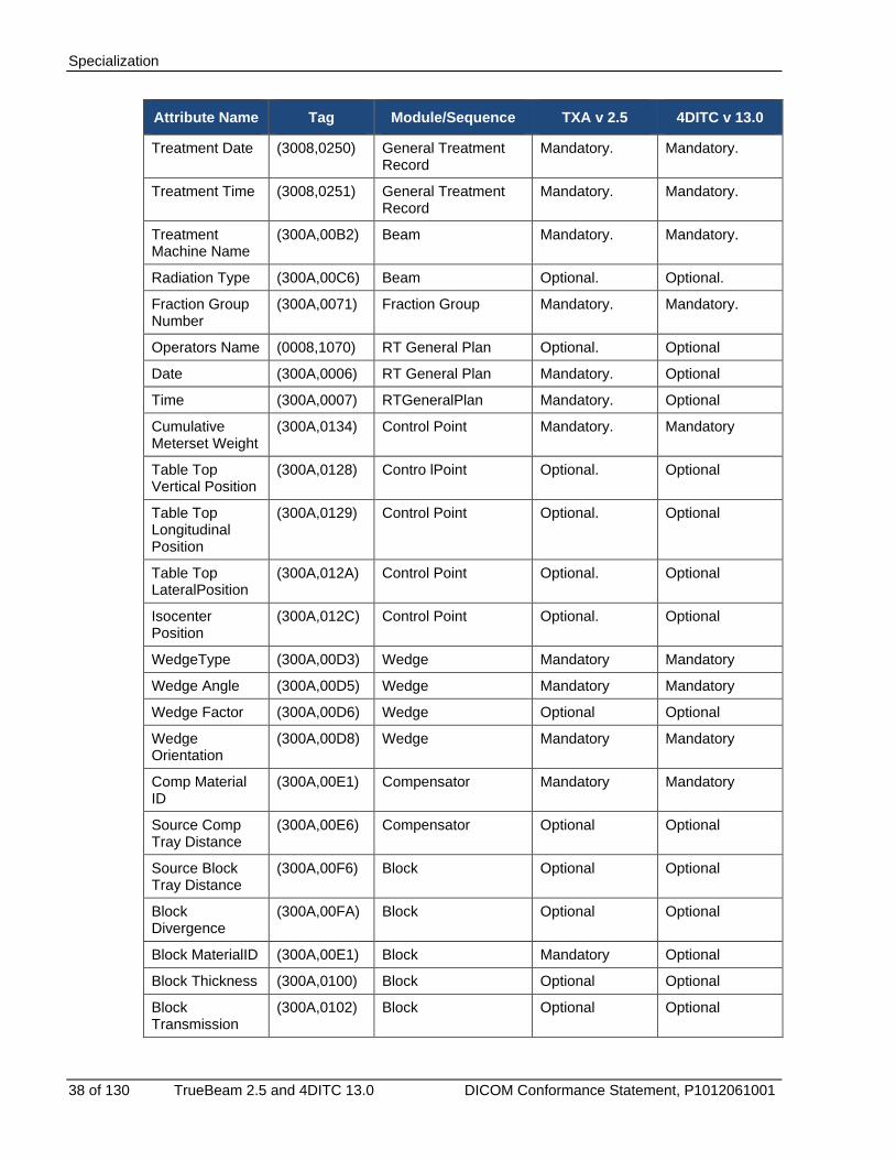
38 of 130 TrueBeam 2.5 and 4DITC 13.0 DICOM Conformance Statement, P1012061001
Attribute Name Tag Module/Sequence TXA v 2.5 4DITC v 13.0
Treatment Date (3008,0250) General Treatment Record
Mandatory. Mandatory.
Treatment Time (3008,0251) General Treatment Record
Mandatory. Mandatory.
Treatment Machine Name
(300A,00B2) Beam Mandatory. Mandatory.
Radiation Type (300A,00C6) Beam Optional. Optional.
Fraction Group Number
(300A,0071) Fraction Group Mandatory. Mandatory.
Operators Name (0008,1070) RT General Plan Optional. Optional
Date (300A,0006) RT General Plan Mandatory. Optional
Time (300A,0007) RTGeneralPlan Mandatory. Optional
Cumulative Meterset Weight
(300A,0134) Control Point Mandatory. Mandatory
Table Top Vertical Position
(300A,0128) Contro lPoint Optional. Optional
Table Top Longitudinal Position
(300A,0129) Control Point Optional. Optional
Table Top LateralPosition
(300A,012A) Control Point Optional. Optional
Isocenter Position
(300A,012C) Control Point Optional. Optional
WedgeType (300A,00D3) Wedge Mandatory Mandatory
Wedge Angle (300A,00D5) Wedge Mandatory Mandatory
Wedge Factor (300A,00D6) Wedge Optional Optional
Wedge Orientation
(300A,00D8) Wedge Mandatory Mandatory
Comp Material ID
(300A,00E1) Compensator Mandatory Mandatory
Source Comp Tray Distance
(300A,00E6) Compensator Optional Optional
Source Block Tray Distance
(300A,00F6) Block Optional Optional
Block Divergence
(300A,00FA) Block Optional Optional
Block MaterialID (300A,00E1) Block Mandatory Optional
Block Thickness (300A,0100) Block Optional Optional
Block Transmission
(300A,0102) Block Optional Optional

Specialization
TrueBeam 2.5 and 4DITC 13.0 DICOM Conformance Statement, P1012061001 39 of 130
Attribute Name Tag Module/Sequence TXA v 2.5 4DITC v 13.0
Block Number Of Points
(300A,0104) Block Mandatory Optional
Block Data (300A,0106) Block Mandatory Optional
Table A-2: Varian V&R Console handling of RT Plan IOD DICOM Type 2 attributes
Type 3 attributes are optional and may be absent except the attributes listed in Table A-3.
Attribute Name Tag Module/Sequence TXA v2.5 4DITC v13.0
Beam Name (300A,00C2) Beam Mandatory Unique beam identification for the User Interface.
Optional
Treatment Delivery Type
(300A,00CE) Beam Mandatory Optional
Tolerance Table Label
(300A,0043) Tolerance Table Mandatory This attribute is being used for unique tolerance table identification.
Optional
Dose Reference Description
(300A,0016) Dose Reference Sequence
Mandatory This attribute is being used for unique dose reference identification.
Mandatory
Table A-3: Varian V&R Console handling of RT Plan IOD DICOM Type 3 attributes
A.2 Data Dictionary of Private Attributes A.2.1 Privatization for RT Plan Storage SOP class
The DICOM Extended Interface is a private group added to the RT Plan IOD. This group contains an XML stream that contains the Plan Extended Interface described in Appendix D.
Attribute Name Tag Type Attribute Description VR
Extended Interface Data (3253,xx00) 3 XML stream. LT
Extended Interface Length
(3253,xx01) 3 Data length of the XML stream IS
Extended Interface Format
(3253,xx02) 3 Extended Interface Format tag. A possible value is: ‘ExtendedIF’
CS
Table A-4: RT Plan Module Privatization
Specialization
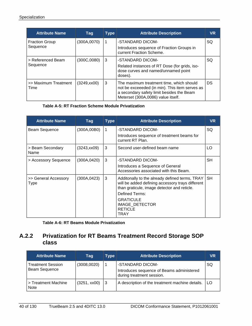
40 of 130 TrueBeam 2.5 and 4DITC 13.0 DICOM Conformance Statement, P1012061001
Attribute Name Tag Type Attribute Description VR
Fraction Group Sequence
(300A,0070) 1 -STANDARD DICOM- Introduces sequence of Fraction Groups in current Fraction Scheme.
SQ
> Referenced Beam Sequence
(300C,0080) 3 -STANDARD DICOM- Related instances of RT Dose (for grids, iso-dose curves and named/unnamed point doses).
SQ
>> Maximum Treatment Time
(3249,xx00) 3 The maximum treatment time, which should not be exceeeded (in min). This item serves as a secondary safety limit besides the Beam Meterset (300A,0086) value itself.
DS
Table A-5: RT Fraction Scheme Module Privatization
Attribute Name Tag Type Attribute Description VR
Beam Sequence (300A,00B0) 1 -STANDARD DICOM- Introduces sequence of treatment beams for current RT Plan.
SQ
> Beam Secondary Name
(3243,xx09) 3 Second user-defined beam name LO
> Accessory Sequence (300A,0420) 3 -STANDARD DICOM- Introduces a Sequence of General Accessories associated with this Beam.
SH
>> General Accessory Type
(300A,0423) 3 Additonally to the already defined terms, TRAY will be added defining accessory trays different than graticule, image detector and reticle. Defined Terms: GRATICULE IMAGE_DETECTOR RETICLE TRAY
SH
Table A-6: RT Beams Module Privatization
A.2.2 Privatization for RT Beams Treatment Record Storage SOP class
Attribute Name Tag Type Attribute Description VR
Treatment Session Beam Sequence
(3008,0020) 1 -STANDARD DICOM- Introduces sequence of Beams administered during treatment session.
SQ
> Treatment Machine Note
(3251, xx00) 3 A description of the treatment machine details. LO
Specialization
TrueBeam 2.5 and 4DITC 13.0 DICOM Conformance Statement, P1012061001 41 of 130
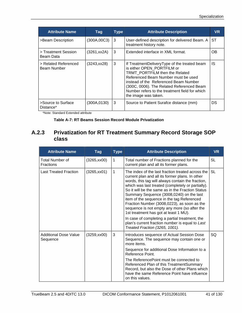
Attribute Name Tag Type Attribute Description VR
>Beam Description (300A,00C3) 3 User-defined description for delivered Beam. A treatment history note.
ST
> Treatment Session Beam Data
(3261,xx2A) 3 Extended interface in XML format. OB
> Related Referenced Beam Number
(3243,xx28) 3 If TreatmentDeliveryType of the treated beam is either OPEN_PORTFILM or TRMT_PORTFILM then the Related Referenced Beam Number must be used instead of the Referenced Beam Number (300C, 0006). The Related Referenced Beam Number refers to the treatment field for which the image was taken.
IS
>Source to Surface Distance*
(300A,0130) 3 Source to Patient Surafce distance (mm) DS
*Note: Standard Extended attribute
Table A-7: RT Beams Session Record Module Privatization
A.2.3 Privatization for RT Treatment Summary Record Storage SOP class
Attribute Name Tag Type Attribute Description VR
Total Number of Fractions
(3265,xx00) 1 Total number of Fractions planned for the current plan and all its former plans.
SL
Last Treated Fraction (3265,xx01) 1 The index of the last fraction treated across the current plan and all its former plans. In other words, this tag will always contain the fraction, which was last treated (completely or partially). So it will be the same as in the Fraction Status Summary Sequence (3008,0240) on the last item of the sequence in the tag Referenced Fraction Number (3008,0223), as soon as the sequence is not empty any more (so after the 1st treatment has got at least 1 MU). In case of completing a partial treatment, the plan’s current fraction number is equal to Last Treated Fraction (3265, 1001).
SL
Additional Dose Value Sequence
(3259,xx00) 3 Introduces sequence of Actual Session Dose Sequence. The sequence may contain one or more items. Sequence for additional Dose Information to a Reference Point. The ReferencePoint must be connected to Referenced Plan of this TreatmentSummary Record, but also the Dose of other Plans which have the same Reference Point have influence on this values.
SQ
Specialization
42 of 130 TrueBeam 2.5 and 4DITC 13.0 DICOM Conformance Statement, P1012061001
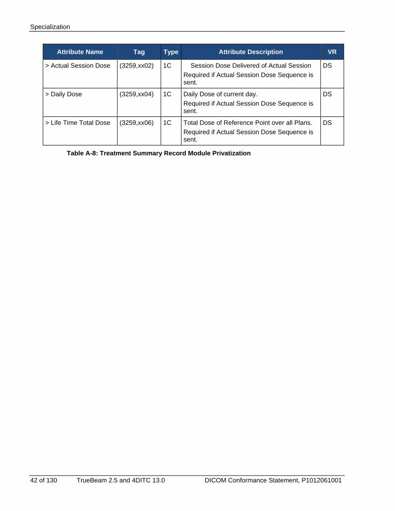
Attribute Name Tag Type Attribute Description VR
> Actual Session Dose (3259,xx02) 1C Session Dose Delivered of Actual Session Required if Actual Session Dose Sequence is sent.
DS
> Daily Dose (3259,xx04) 1C Daily Dose of current day. Required if Actual Session Dose Sequence is sent.
DS
> Life Time Total Dose (3259,xx06) 1C Total Dose of Reference Point over all Plans. Required if Actual Session Dose Sequence is sent.
DS
Table A-8: Treatment Summary Record Module Privatization
DICOM Query Retrieve Service Class Object Matching Criteria (SCU)
TrueBeam 2.5 and 4DITC 13.0 DICOM Conformance Statement, P1012061001 43 of 130
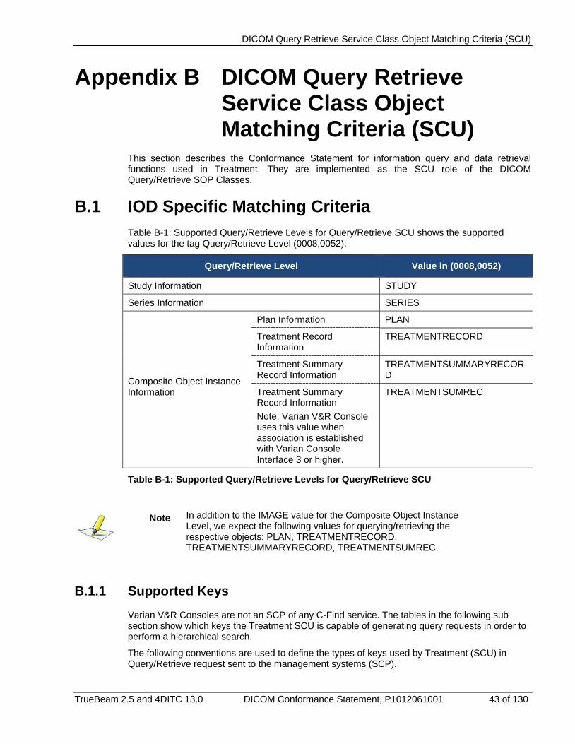
Appendix B DICOM Query Retrieve Service Class Object Matching Criteria (SCU)
This section describes the Conformance Statement for information query and data retrieval functions used in Treatment. They are implemented as the SCU role of the DICOM Query/Retrieve SOP Classes.
B.1 IOD Specific Matching Criteria Table B-1: Supported Query/Retrieve Levels for Query/Retrieve SCU shows the supported values for the tag Query/Retrieve Level (0008,0052):
Query/Retrieve Level Value in (0008,0052)
Study Information STUDY
Series Information SERIES
Composite Object Instance Information
Plan Information PLAN
Treatment Record Information
TREATMENTRECORD
Treatment Summary Record Information
TREATMENTSUMMARYRECORD
Treatment Summary Record Information Note: Varian V&R Console uses this value when association is established with Varian Console Interface 3 or higher.
TREATMENTSUMREC
Table B-1: Supported Query/Retrieve Levels for Query/Retrieve SCU
Note In addition to the IMAGE value for the Composite Object Instance Level, we expect the following values for querying/retrieving the respective objects: PLAN, TREATMENTRECORD, TREATMENTSUMMARYRECORD, TREATMENTSUMREC.
B.1.1 Supported Keys Varian V&R Consoles are not an SCP of any C-Find service. The tables in the following sub section show which keys the Treatment SCU is capable of generating query requests in order to perform a hierarchical search.
The following conventions are used to define the types of keys used by Treatment (SCU) in Query/Retrieve request sent to the management systems (SCP).
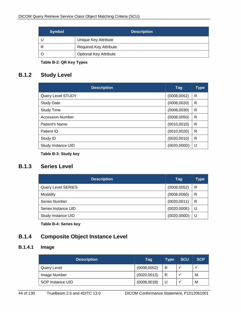
DICOM Query Retrieve Service Class Object Matching Criteria (SCU)
44 of 130 TrueBeam 2.5 and 4DITC 13.0 DICOM Conformance Statement, P1012061001
Symbol Description
U Unique Key Attribute
R Required Key Attribute
O Optional Key Attribute
Table B-2: QR Key Types
B.1.2 Study Level
Description Tag Type
Query Level STUDY (0008,0052) R
Study Date (0008,0020) R
Study Time (0008,0030) R
Accession Number (0008,0050) R
Patient's Name (0010,0010) R
Patient ID (0010,0020) R
Study ID (0020,0010) R
Study Instance UID (0020,000D) U
Table B-3: Study key
B.1.3 Series Level
Description Tag Type
Query Level SERIES (0008,0052) R
Modality (0008,0060) R
Series Number (0020,0011) R
Series Instance UID (0020,000E) U
Study Instance UID (0020,000D) U
Table B-4: Series key
B.1.4 Composite Object Instance Level
B.1.4.1 Image
Description Tag Type SCU SCP
Query Level (0008,0052) R
Image Number (0020,0013) R M
SOP Instance UID (0008,0018) U M
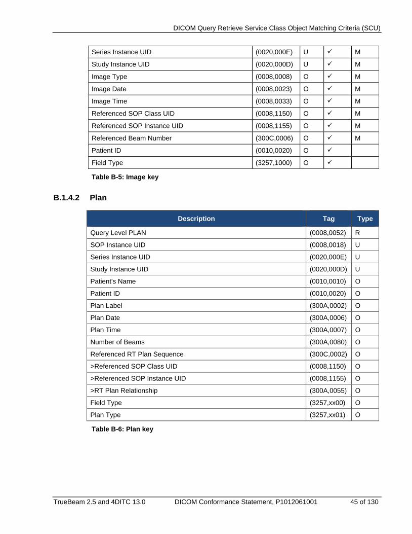
DICOM Query Retrieve Service Class Object Matching Criteria (SCU)
TrueBeam 2.5 and 4DITC 13.0 DICOM Conformance Statement, P1012061001 45 of 130
Series Instance UID (0020,000E) U M
Study Instance UID (0020,000D) U M
Image Type (0008,0008) O M
Image Date (0008,0023) O M
Image Time (0008,0033) O M
Referenced SOP Class UID (0008,1150) O M
Referenced SOP Instance UID (0008,1155) O M
Referenced Beam Number (300C,0006) O M
Patient ID (0010,0020) O
Field Type (3257,1000) O
Table B-5: Image key
B.1.4.2 Plan
Description Tag Type
Query Level PLAN (0008,0052) R
SOP Instance UID (0008,0018) U
Series Instance UID (0020,000E) U
Study Instance UID (0020,000D) U
Patient's Name (0010,0010) O
Patient ID (0010,0020) O
Plan Label (300A,0002) O
Plan Date (300A,0006) O
Plan Time (300A,0007) O
Number of Beams (300A,0080) O
Referenced RT Plan Sequence (300C,0002) O
>Referenced SOP Class UID (0008,1150) O
>Referenced SOP Instance UID (0008,1155) O
>RT Plan Relationship (300A,0055) O
Field Type (3257,xx00) O
Plan Type (3257,xx01) O
Table B-6: Plan key
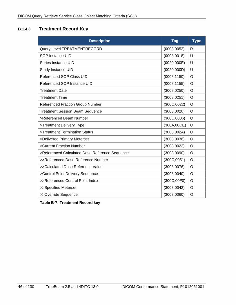
DICOM Query Retrieve Service Class Object Matching Criteria (SCU)
46 of 130 TrueBeam 2.5 and 4DITC 13.0 DICOM Conformance Statement, P1012061001
B.1.4.3 Treatment Record Key
Description Tag Type
Query Level TREATMENTRECORD (0008,0052) R
SOP Instance UID (0008,0018) U
Series Instance UID (0020,000E) U
Study Instance UID (0020,000D) U
Referenced SOP Class UID (0008,1150) O
Referenced SOP Instance UID (0008,1155) O
Treatment Date (3008,0250) O
Treatment Time (3008,0251) O
Referenced Fraction Group Number (300C,0022) O
Treatment Session Beam Sequence (3008,0020) O
>Referenced Beam Number (300C,0006) O
>Treatment Delivery Type (300A,00CE) O
>Treatment Termination Status (3008,002A) O
>Delivered Primary Meterset (3008,0036) O
>Current Fraction Number (3008,0022) O
>Referenced Calculated Dose Reference Sequence (3008,0090) O
>>Referenced Dose Reference Number (300C,0051) O
>>Calculated Dose Reference Value (3008,0076) O
>Control Point Delivery Sequence (3008,0040) O
>>Referenced Control Point Index (300C,00F0) O
>>Specified Meterset (3008,0042) O
>>Override Sequence (3008,0060) O
Table B-7: Treatment Record key
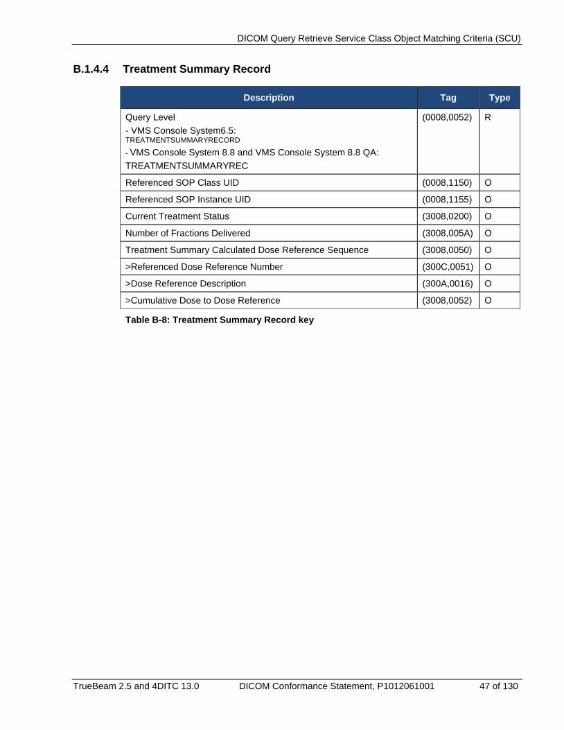
DICOM Query Retrieve Service Class Object Matching Criteria (SCU)
TrueBeam 2.5 and 4DITC 13.0 DICOM Conformance Statement, P1012061001 47 of 130
B.1.4.4 Treatment Summary Record
Description Tag Type
Query Level - VMS Console System6.5: TREATMENTSUMMARYRECORD
- VMS Console System 8.8 and VMS Console System 8.8 QA: TREATMENTSUMMARYREC
(0008,0052) R
Referenced SOP Class UID (0008,1150) O
Referenced SOP Instance UID (0008,1155) O
Current Treatment Status (3008,0200) O
Number of Fractions Delivered (3008,005A) O
Treatment Summary Calculated Dose Reference Sequence (3008,0050) O
>Referenced Dose Reference Number (300C,0051) O
>Dose Reference Description (300A,0016) O
>Cumulative Dose to Dose Reference (3008,0052) O
Table B-8: Treatment Summary Record key
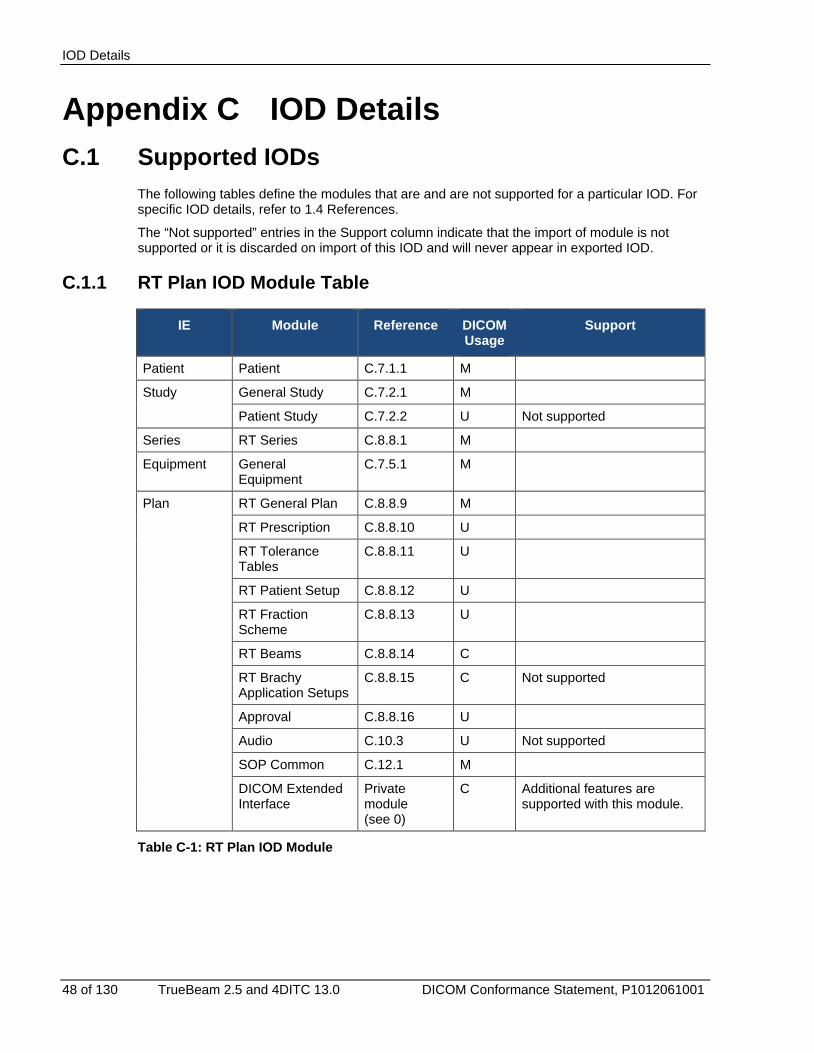
IOD Details
48 of 130 TrueBeam 2.5 and 4DITC 13.0 DICOM Conformance Statement, P1012061001
Appendix C IOD Details C.1 Supported IODs
The following tables define the modules that are and are not supported for a particular IOD. For specific IOD details, refer to 1.4 References.
The “Not supported” entries in the Support column indicate that the import of module is not supported or it is discarded on import of this IOD and will never appear in exported IOD.
C.1.1 RT Plan IOD Module Table
IE Module Reference DICOM Usage
Support
Patient Patient C.7.1.1 M
Study General Study C.7.2.1 M
Patient Study C.7.2.2 U Not supported
Series RT Series C.8.8.1 M
Equipment General Equipment
C.7.5.1 M
Plan RT General Plan C.8.8.9 M
RT Prescription C.8.8.10 U
RT Tolerance Tables
C.8.8.11 U
RT Patient Setup C.8.8.12 U
RT Fraction Scheme
C.8.8.13 U
RT Beams C.8.8.14 C
RT Brachy Application Setups
C.8.8.15 C Not supported
Approval C.8.8.16 U
Audio C.10.3 U Not supported
SOP Common C.12.1 M
DICOM Extended Interface
Private module (see 0)
C Additional features are supported with this module.
Table C-1: RT Plan IOD Module
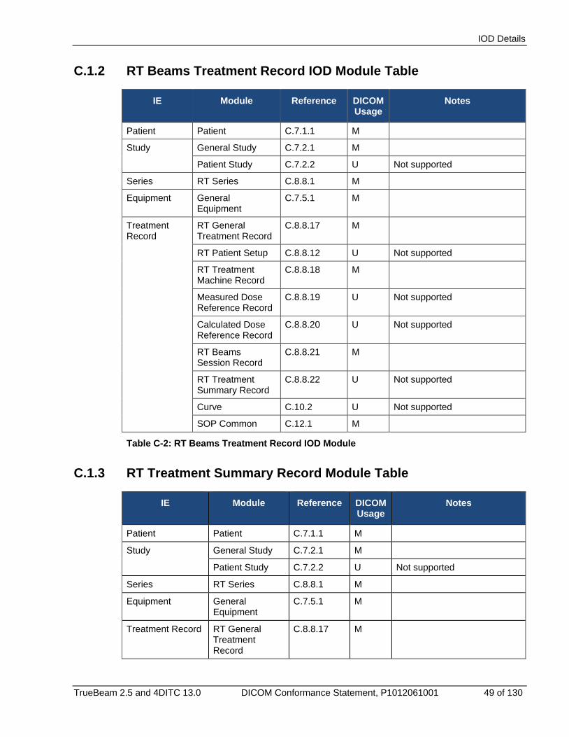
IOD Details
TrueBeam 2.5 and 4DITC 13.0 DICOM Conformance Statement, P1012061001 49 of 130
C.1.2 RT Beams Treatment Record IOD Module Table
IE Module Reference DICOM Usage
Notes
Patient Patient C.7.1.1 M
Study General Study C.7.2.1 M
Patient Study C.7.2.2 U Not supported
Series RT Series C.8.8.1 M
Equipment General Equipment
C.7.5.1 M
Treatment Record
RT General Treatment Record
C.8.8.17 M
RT Patient Setup C.8.8.12 U Not supported
RT Treatment Machine Record
C.8.8.18 M
Measured Dose Reference Record
C.8.8.19 U Not supported
Calculated Dose Reference Record
C.8.8.20 U Not supported
RT Beams Session Record
C.8.8.21 M
RT Treatment Summary Record
C.8.8.22 U Not supported
Curve C.10.2 U Not supported
SOP Common C.12.1 M
Table C-2: RT Beams Treatment Record IOD Module
C.1.3 RT Treatment Summary Record Module Table
IE Module Reference DICOM Usage
Notes
Patient Patient C.7.1.1 M
Study General Study C.7.2.1 M
Patient Study C.7.2.2 U Not supported
Series RT Series C.8.8.1 M
Equipment General Equipment
C.7.5.1 M
Treatment Record RT General Treatment Record
C.8.8.17 M
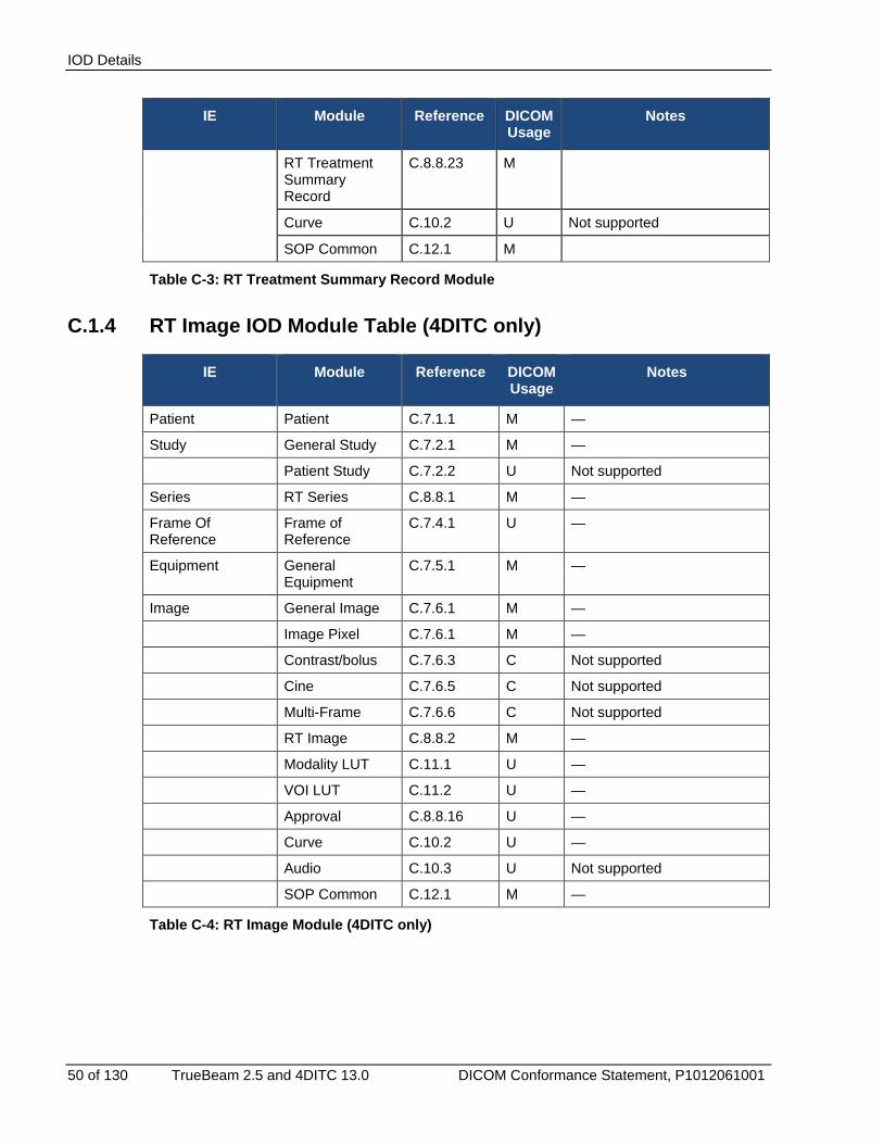
IOD Details
50 of 130 TrueBeam 2.5 and 4DITC 13.0 DICOM Conformance Statement, P1012061001
IE Module Reference DICOM Usage
Notes
RT Treatment Summary Record
C.8.8.23 M
Curve C.10.2 U Not supported
SOP Common C.12.1 M
Table C-3: RT Treatment Summary Record Module
C.1.4 RT Image IOD Module Table (4DITC only)
IE Module Reference DICOM Usage
Notes
Patient Patient C.7.1.1 M —
Study General Study C.7.2.1 M —
Patient Study C.7.2.2 U Not supported
Series RT Series C.8.8.1 M —
Frame Of Reference
Frame of Reference
C.7.4.1 U —
Equipment General Equipment
C.7.5.1 M —
Image General Image C.7.6.1 M —
Image Pixel C.7.6.1 M —
Contrast/bolus C.7.6.3 C Not supported
Cine C.7.6.5 C Not supported
Multi-Frame C.7.6.6 C Not supported
RT Image C.8.8.2 M —
Modality LUT C.11.1 U —
VOI LUT C.11.2 U —
Approval C.8.8.16 U —
Curve C.10.2 U —
Audio C.10.3 U Not supported
SOP Common C.12.1 M —
Table C-4: RT Image Module (4DITC only)
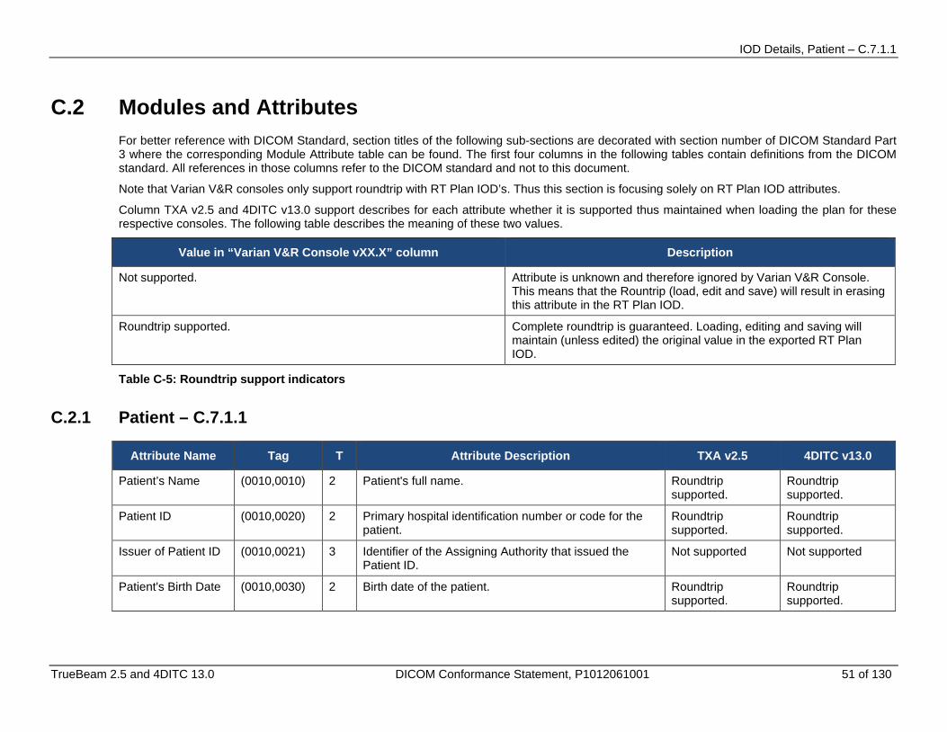
IOD Details, Patient – C.7.1.1
TrueBeam 2.5 and 4DITC 13.0 DICOM Conformance Statement, P1012061001 51 of 130
C.2 Modules and Attributes For better reference with DICOM Standard, section titles of the following sub-sections are decorated with section number of DICOM Standard Part 3 where the corresponding Module Attribute table can be found. The first four columns in the following tables contain definitions from the DICOM standard. All references in those columns refer to the DICOM standard and not to this document.
Note that Varian V&R consoles only support roundtrip with RT Plan IOD’s. Thus this section is focusing solely on RT Plan IOD attributes. Column TXA v2.5 and 4DITC v13.0 support describes for each attribute whether it is supported thus maintained when loading the plan for these respective consoles. The following table describes the meaning of these two values.
Value in “Varian V&R Console vXX.X” column Description
Not supported. Attribute is unknown and therefore ignored by Varian V&R Console. This means that the Rountrip (load, edit and save) will result in erasing this attribute in the RT Plan IOD.
Roundtrip supported. Complete roundtrip is guaranteed. Loading, editing and saving will maintain (unless edited) the original value in the exported RT Plan IOD.
Table C-5: Roundtrip support indicators
C.2.1 Patient – C.7.1.1
Attribute Name Tag T Attribute Description TXA v2.5 4DITC v13.0
Patient’s Name (0010,0010) 2 Patient's full name. Roundtrip supported.
Roundtrip supported.
Patient ID (0010,0020) 2 Primary hospital identification number or code for the patient.
Roundtrip supported.
Roundtrip supported.
Issuer of Patient ID (0010,0021) 3 Identifier of the Assigning Authority that issued the Patient ID.
Not supported Not supported
Patient's Birth Date (0010,0030) 2 Birth date of the patient. Roundtrip supported.
Roundtrip supported.

IOD Details, Patient – C.7.1.1
52 of 130 TrueBeam 2.5 and 4DITC 13.0 DICOM Conformance Statement, P1012061001
Attribute Name Tag T Attribute Description TXA v2.5 4DITC v13.0
Patient's Sex (0010,0040) 2 Sex of the named patient. Enumerated Values: M = male F = female O = other
Roundtrip supported.
Roundtrip supported.
Referenced Patient Sequence
(0008,1120) 3 A sequence that provides reference to a Patient SOP Class/Instance pair. Only a single Item shall be permitted in this Sequence.
Not supported Not supported
> Referenced SOP Class UID
(0008,1150) 1C Uniquely identifies the referenced SOP Class. Required if Referenced Patient Sequence (0008,1120) is sent.
Not supported Not supported
> Referenced SOP Instance UID
(0008,1155) 1C Uniquely identifies the referenced SOP Instance. Required if Referenced Patient Sequence (0008,1120) is sent.
Not supported Not supported
Patient's Birth Time (0010,0032) 3 Birth time of the Patient. Roundtrip supported.
Roundtrip supported.
Other Patient IDs (0010,1000) 3 Other identification numbers or codes used to identify the patient.
Roundtrip supported.
Roundtrip supported.
Other Patient Names
(0010,1001) 3 Other names used to identify the patient. Not supported Not supported
Ethnic Group (0010,2160) 3 Ethnic group or race of the patient. Roundtrip supported.
Roundtrip supported.
Patient Comments (0010,4000) 3 User-defined additional information about the patient. Roundtrip supported.d.
Roundtrip supported.
Patient Identify Removed
(0012,0062) 3 The true identity of the patient has been removed from the Attributes and the Pixel Data Enumerated Values: YES NO
Not supported Not supported
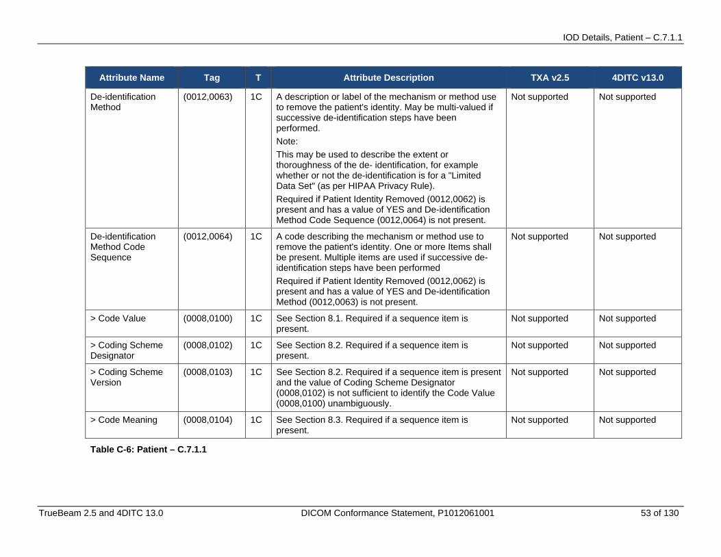
IOD Details, Patient – C.7.1.1
TrueBeam 2.5 and 4DITC 13.0 DICOM Conformance Statement, P1012061001 53 of 130
Attribute Name Tag T Attribute Description TXA v2.5 4DITC v13.0
De-identification Method
(0012,0063) 1C A description or label of the mechanism or method use to remove the patient's identity. May be multi-valued if successive de-identification steps have been performed. Note: This may be used to describe the extent or thoroughness of the de- identification, for example whether or not the de-identification is for a "Limited Data Set" (as per HIPAA Privacy Rule). Required if Patient Identity Removed (0012,0062) is present and has a value of YES and De-identification Method Code Sequence (0012,0064) is not present.
Not supported Not supported
De-identification Method Code Sequence
(0012,0064) 1C A code describing the mechanism or method use to remove the patient's identity. One or more Items shall be present. Multiple items are used if successive de-identification steps have been performed Required if Patient Identity Removed (0012,0062) is present and has a value of YES and De-identification Method (0012,0063) is not present.
Not supported Not supported
> Code Value (0008,0100) 1C See Section 8.1. Required if a sequence item is present.
Not supported Not supported
> Coding Scheme Designator
(0008,0102) 1C See Section 8.2. Required if a sequence item is present.
Not supported Not supported
> Coding Scheme Version
(0008,0103) 1C See Section 8.2. Required if a sequence item is present and the value of Coding Scheme Designator (0008,0102) is not sufficient to identify the Code Value (0008,0100) unambiguously.
Not supported Not supported
> Code Meaning (0008,0104) 1C See Section 8.3. Required if a sequence item is present.
Not supported Not supported
Table C-6: Patient – C.7.1.1

IOD Details, General Study - C.7.2.1
54 of 130 TrueBeam 2.5 and 4DITC 13.0 DICOM Conformance Statement, P1012061001
C.2.2 General Study - C.7.2.1
Attribute Name Tag T Attribute Description TXA v2.5 4DITC v13.0
Study Instance UID (0020,000D) 1 Unique identifier for the Study. Roundtrip supported
Roundtrip supported
Study Date (0008,0020) 2 Date the Study started. Roundtrip supported
Roundtrip supported
Study Time (0008,0030) 2 Time the Study started. Roundtrip supported
Roundtrip supported
Referring Physician’s Name
(0008,0090) 2 Name of the patient's referring physician Roundtrip supported
Roundtrip supported
Referring Physician Identification Sequence
(0008,0096) 3 Identification of the patient's referring physician. Only a single item shall be permitted in this sequence.
Not supported Not supported
> Person Identification Code Sequence
(0040,1101) 1 A coded entry which identifies a person. The Code Meaning attribute, though it will be encoded with a VR of LO, may be encoded according to the rules of the PN VR (e.g. caret '^' delimiters shall separate name components), except that a single component (i.e. the whole name unseparated by caret delimiters) is not permitted. Name component groups for use with multi-byte character sets are permitted, as long as they fit within the 64 characters (the length of the LO VR). One or more Items may be permitted in this Sequence.
Not supported Not supported
>> Code Value (0008,0100) 1C See Section 8.1. Required if a sequence item is present.
Not supported Not supported
>> Coding Scheme Designator
(0008,0102) 1C See Section 8.2. Required if a sequence item is present.
Not supported Not supported
>> Coding Scheme Version
(0008,0103) 1C See Section 8.2. Required if a sequence item is present and the value of Coding Scheme Designator (0008,0102) is not sufficient to identify the Code Value (0008,0100) unambiguously.
Not supported Not supported
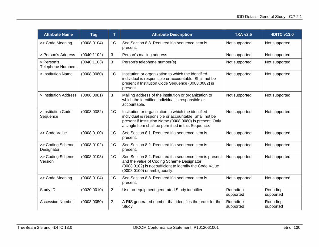
IOD Details, General Study - C.7.2.1
TrueBeam 2.5 and 4DITC 13.0 DICOM Conformance Statement, P1012061001 55 of 130
Attribute Name Tag T Attribute Description TXA v2.5 4DITC v13.0
>> Code Meaning (0008,0104) 1C See Section 8.3. Required if a sequence item is present.
Not supported Not supported
> Person’s Address (0040,1102) 3 Person's mailing address Not supported Not supported
> Person’s Telephone Numbers
(0040,1103) 3 Person's telephone number(s) Not supported Not supported
> Institution Name (0008,0080) 1C Institution or organization to which the identified individual is responsible or accountable. Shall not be present if Institution Code Sequence (0008,0082) is present.
Not supported Not supported
> Institution Address (0008,0081) 3 Mailing address of the institution or organization to which the identified individual is responsible or accountable.
Not supported Not supported
> Institution Code Sequence
(0008,0082) 1C Institution or organization to which the identified individual is responsible or accountable. Shall not be present if Institution Name (0008,0080) is present. Only a single Item shall be permitted in this Sequence.
Not supported Not supported
>> Code Value (0008,0100) 1C See Section 8.1. Required if a sequence item is present.
Not supported Not supported
>> Coding Scheme Designator
(0008,0102) 1C See Section 8.2. Required if a sequence item is present.
Not supported Not supported
>> Coding Scheme Version
(0008,0103) 1C See Section 8.2. Required if a sequence item is present and the value of Coding Scheme Designator (0008,0102) is not sufficient to identify the Code Value (0008,0100) unambiguously.
Not supported Not supported
>> Code Meaning (0008,0104) 1C See Section 8.3. Required if a sequence item is present.
Not supported Not supported
Study ID (0020,0010) 2 User or equipment generated Study identifier. Roundtrip supported
Roundtrip supported
Accession Number (0008,0050) 2 A RIS generated number that identifies the order for the Study.
Roundtrip supported
Roundtrip supported
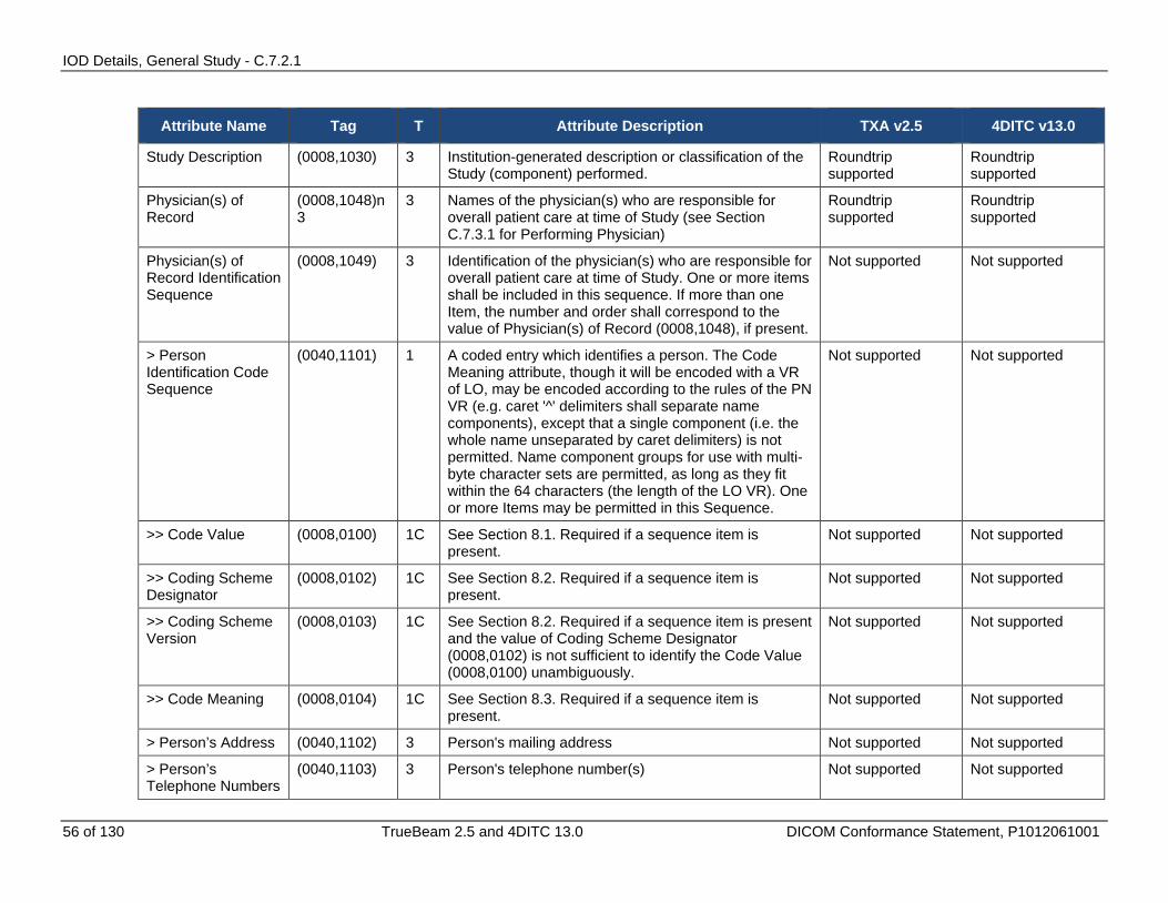
IOD Details, General Study - C.7.2.1
56 of 130 TrueBeam 2.5 and 4DITC 13.0 DICOM Conformance Statement, P1012061001
Attribute Name Tag T Attribute Description TXA v2.5 4DITC v13.0
Study Description (0008,1030) 3 Institution-generated description or classification of the Study (component) performed.
Roundtrip supported
Roundtrip supported
Physician(s) of Record
(0008,1048)n 3
3 Names of the physician(s) who are responsible for overall patient care at time of Study (see Section C.7.3.1 for Performing Physician)
Roundtrip supported
Roundtrip supported
Physician(s) of Record Identification Sequence
(0008,1049) 3 Identification of the physician(s) who are responsible for overall patient care at time of Study. One or more items shall be included in this sequence. If more than one Item, the number and order shall correspond to the value of Physician(s) of Record (0008,1048), if present.
Not supported Not supported
> Person Identification Code Sequence
(0040,1101) 1 A coded entry which identifies a person. The Code Meaning attribute, though it will be encoded with a VR of LO, may be encoded according to the rules of the PN VR (e.g. caret '^' delimiters shall separate name components), except that a single component (i.e. the whole name unseparated by caret delimiters) is not permitted. Name component groups for use with multi-byte character sets are permitted, as long as they fit within the 64 characters (the length of the LO VR). One or more Items may be permitted in this Sequence.
Not supported Not supported
>> Code Value (0008,0100) 1C See Section 8.1. Required if a sequence item is present.
Not supported Not supported
>> Coding Scheme Designator
(0008,0102) 1C See Section 8.2. Required if a sequence item is present.
Not supported Not supported
>> Coding Scheme Version
(0008,0103) 1C See Section 8.2. Required if a sequence item is present and the value of Coding Scheme Designator (0008,0102) is not sufficient to identify the Code Value (0008,0100) unambiguously.
Not supported Not supported
>> Code Meaning (0008,0104) 1C See Section 8.3. Required if a sequence item is present.
Not supported Not supported
> Person’s Address (0040,1102) 3 Person's mailing address Not supported Not supported
> Person’s Telephone Numbers
(0040,1103) 3 Person's telephone number(s) Not supported Not supported
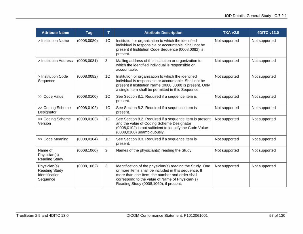
IOD Details, General Study - C.7.2.1
TrueBeam 2.5 and 4DITC 13.0 DICOM Conformance Statement, P1012061001 57 of 130
Attribute Name Tag T Attribute Description TXA v2.5 4DITC v13.0
> Institution Name (0008,0080) 1C Institution or organization to which the identified individual is responsible or accountable. Shall not be present if Institution Code Sequence (0008,0082) is present.
Not supported Not supported
> Institution Address (0008,0081) 3 Mailing address of the institution or organization to which the identified individual is responsible or accountable.
Not supported Not supported
> Institution Code Sequence
(0008,0082) 1C Institution or organization to which the identified individual is responsible or accountable. Shall not be present if Institution Name (0008,0080) is present. Only a single Item shall be permitted in this Sequence.
Not supported Not supported
>> Code Value (0008,0100) 1C See Section 8.1. Required if a sequence item is present.
Not supported Not supported
>> Coding Scheme Designator
(0008,0102) 1C See Section 8.2. Required if a sequence item is present.
Not supported Not supported
>> Coding Scheme Version
(0008,0103) 1C See Section 8.2. Required if a sequence item is present and the value of Coding Scheme Designator (0008,0102) is not sufficient to identify the Code Value (0008,0100) unambiguously.
Not supported Not supported
>> Code Meaning (0008,0104) 1C See Section 8.3. Required if a sequence item is present.
Not supported Not supported
Name of Physician(s) Reading Study
(0008,1060) 3 Names of the physician(s) reading the Study. Not supported Not supported
Physician(s) Reading Study Identification Sequence
(0008,1062) 3 Identification of the physician(s) reading the Study. One or more items shall be included in this sequence. If more than one Item, the number and order shall correspond to the value of Name of Physician(s) Reading Study (0008,1060), if present.
Not supported Not supported
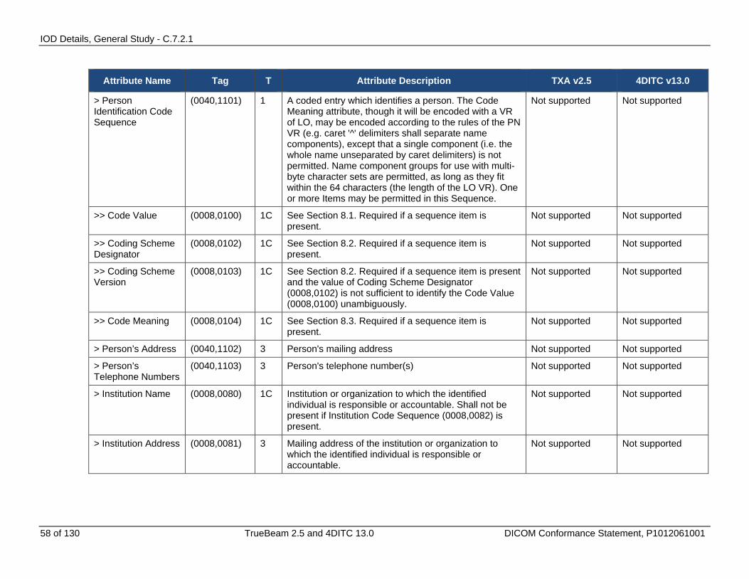
IOD Details, General Study - C.7.2.1
58 of 130 TrueBeam 2.5 and 4DITC 13.0 DICOM Conformance Statement, P1012061001
Attribute Name Tag T Attribute Description TXA v2.5 4DITC v13.0
> Person Identification Code Sequence
(0040,1101) 1 A coded entry which identifies a person. The Code Meaning attribute, though it will be encoded with a VR of LO, may be encoded according to the rules of the PN VR (e.g. caret '^' delimiters shall separate name components), except that a single component (i.e. the whole name unseparated by caret delimiters) is not permitted. Name component groups for use with multi-byte character sets are permitted, as long as they fit within the 64 characters (the length of the LO VR). One or more Items may be permitted in this Sequence.
Not supported Not supported
>> Code Value (0008,0100) 1C See Section 8.1. Required if a sequence item is present.
Not supported Not supported
>> Coding Scheme Designator
(0008,0102) 1C See Section 8.2. Required if a sequence item is present.
Not supported Not supported
>> Coding Scheme Version
(0008,0103) 1C See Section 8.2. Required if a sequence item is present and the value of Coding Scheme Designator (0008,0102) is not sufficient to identify the Code Value (0008,0100) unambiguously.
Not supported Not supported
>> Code Meaning (0008,0104) 1C See Section 8.3. Required if a sequence item is present.
Not supported Not supported
> Person’s Address (0040,1102) 3 Person's mailing address Not supported Not supported
> Person’s Telephone Numbers
(0040,1103) 3 Person's telephone number(s) Not supported Not supported
> Institution Name (0008,0080) 1C Institution or organization to which the identified individual is responsible or accountable. Shall not be present if Institution Code Sequence (0008,0082) is present.
Not supported Not supported
> Institution Address (0008,0081) 3 Mailing address of the institution or organization to which the identified individual is responsible or accountable.
Not supported Not supported

IOD Details, General Study - C.7.2.1
TrueBeam 2.5 and 4DITC 13.0 DICOM Conformance Statement, P1012061001 59 of 130
Attribute Name Tag T Attribute Description TXA v2.5 4DITC v13.0
> Institution Code Sequence
(0008,0082) 1C Institution or organization to which the identified individual is responsible or accountable. Shall not be present if Institution Name (0008,0080) is present. Only a single Item shall be permitted in this Sequence.
Not supported Not supported
>> Code Value (0008,0100) 1C See Section 8.1. Required if a sequence item is present.
Not supported Not supported
>> Coding Scheme Designator
(0008,0102) 1C See Section 8.2. Required if a sequence item is present.
Not supported Not supported
>> Coding Scheme Version
(0008,0103) 1C See Section 8.2. Required if a sequence item is present and the value of Coding Scheme Designator (0008,0102) is not sufficient to identify the Code Value (0008,0100) unambiguously.
Not supported Not supported
>> Code Meaning (0008,0104) 1C See Section 8.3. Required if a sequence item is present.
Not supported Not supported
Referenced Study Sequence
(0008,1110) 3 A sequence that provides reference to a Study SOP Class/Instance pair. The sequence may have zero or more Items.
Not supported Not supported
> Referenced SOP Class UID
(0008,1150) 1C Uniquely identifies the referenced SOP Class. Required if Referenced Study Sequence (0008,1110) is sent.
Not supported Not supported
> Referenced SOP Instance UID
(0008,1155) 1C Uniquely identifies the referenced SOP Instance. Required if Referenced Study Sequence (0008,1110) is sent.
Not supported Not supported
Procedure Code Sequence
(0008,1032) 3 A Sequence that conveys the type of procedure performed. One or more Items may be included in this Sequence.
Not supported Not supported
> Code Value (0008,0100) 1C See Section 8.1. Required if a sequence item is present.
Not supported Not supported
> Coding Scheme Designator
(0008,0102) 1C See Section 8.2. Required if a sequence item is present.
Not supported Not supported
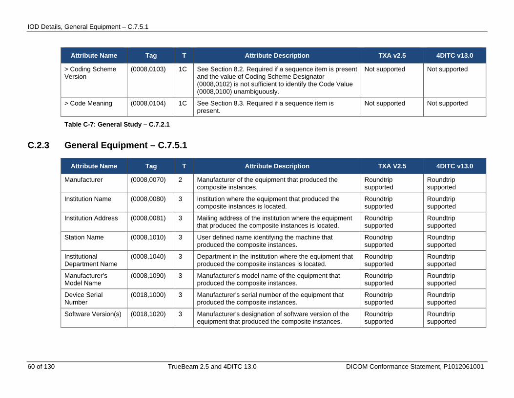
IOD Details, General Equipment – C.7.5.1
60 of 130 TrueBeam 2.5 and 4DITC 13.0 DICOM Conformance Statement, P1012061001
Attribute Name Tag T Attribute Description TXA v2.5 4DITC v13.0
> Coding Scheme Version
(0008,0103) 1C See Section 8.2. Required if a sequence item is present and the value of Coding Scheme Designator (0008,0102) is not sufficient to identify the Code Value (0008,0100) unambiguously.
Not supported Not supported
> Code Meaning (0008,0104) 1C See Section 8.3. Required if a sequence item is present.
Not supported Not supported
Table C-7: General Study – C.7.2.1
C.2.3 General Equipment – C.7.5.1
Attribute Name Tag T Attribute Description TXA V2.5 4DITC v13.0
Manufacturer (0008,0070) 2 Manufacturer of the equipment that produced the composite instances.
Roundtrip supported
Roundtrip supported
Institution Name (0008,0080) 3 Institution where the equipment that produced the composite instances is located.
Roundtrip supported
Roundtrip supported
Institution Address (0008,0081) 3 Mailing address of the institution where the equipment that produced the composite instances is located.
Roundtrip supported
Roundtrip supported
Station Name (0008,1010) 3 User defined name identifying the machine that produced the composite instances.
Roundtrip supported
Roundtrip supported
Institutional Department Name
(0008,1040) 3 Department in the institution where the equipment that produced the composite instances is located.
Roundtrip supported
Roundtrip supported
Manufacturer’s Model Name
(0008,1090) 3 Manufacturer's model name of the equipment that produced the composite instances.
Roundtrip supported
Roundtrip supported
Device Serial Number
(0018,1000) 3 Manufacturer's serial number of the equipment that produced the composite instances.
Roundtrip supported
Roundtrip supported
Software Version(s) (0018,1020) 3 Manufacturer's designation of software version of the equipment that produced the composite instances.
Roundtrip supported
Roundtrip supported
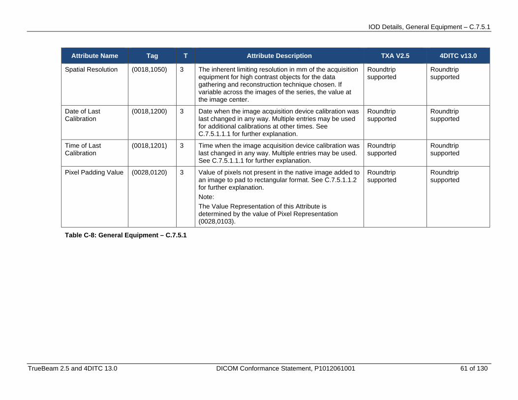
IOD Details, General Equipment – C.7.5.1
TrueBeam 2.5 and 4DITC 13.0 DICOM Conformance Statement, P1012061001 61 of 130
Attribute Name Tag T Attribute Description TXA V2.5 4DITC v13.0
Spatial Resolution (0018,1050) 3 The inherent limiting resolution in mm of the acquisition equipment for high contrast objects for the data gathering and reconstruction technique chosen. If variable across the images of the series, the value at the image center.
Roundtrip supported
Roundtrip supported
Date of Last Calibration
(0018,1200) 3 Date when the image acquisition device calibration was last changed in any way. Multiple entries may be used for additional calibrations at other times. See C.7.5.1.1.1 for further explanation.
Roundtrip supported
Roundtrip supported
Time of Last Calibration
(0018,1201) 3 Time when the image acquisition device calibration was last changed in any way. Multiple entries may be used. See C.7.5.1.1.1 for further explanation.
Roundtrip supported
Roundtrip supported
Pixel Padding Value (0028,0120) 3 Value of pixels not present in the native image added to an image to pad to rectangular format. See C.7.5.1.1.2 for further explanation. Note: The Value Representation of this Attribute is determined by the value of Pixel Representation (0028,0103).
Roundtrip supported
Roundtrip supported
Table C-8: General Equipment – C.7.5.1

IOD Details, RT Series – C.8.8.1
62 of 130 TrueBeam 2.5 and 4DITC 13.0 DICOM Conformance Statement, P1012061001
C.2.4 RT Series – C.8.8.1
Attribute Name Tag T Attribute Description TXA v2.5 4DITC v13.0
Modality (0008,0060) 1 Type of equipment that originally acquired the data. Enumerated Values: RTIMAGE = RT Image RTDOSE = RT Dose RTSTRUCT = RT Structure Set RTPLAN = RT Plan RTRECORD = RT Treatment Record See C.8.8.1.1.
Roundtrip supported
Roundtrip supported
Series Instance UID (0020,000E) 1 Unique identifier of the series. Roundtrip supported
Roundtrip supported
Series Number (0020,0011) 2 A number that identifies this series. Roundtrip supported
Roundtrip supported
Series Description (0008,103E) 3 User provided description of the series. Roundtrip supported.
Roundtrip supported.
Referenced Performed Procedure Step Sequence
(0008,1111) 3 Uniquely identifies the Performed Procedure Step SOP Instance to which the Series is related (e.g. a Modality or General-Purpose Performed Procedure Step SOP Instance). One or more items may be included in this sequence.
Not supported Not supported
> Referenced SOP Class UID
(0008,1150) 1C Uniquely identifies the referenced SOP Class. Required if Referenced Performed Procedure Step Sequence (0008,1111) is sent.
Not supported Not supported
> Referenced SOP Instance UID
(0008,1155) 1C Uniquely identifies the referenced SOP Instance. Required if Referenced Performed Procedure Step Sequence (0008,1111) is sent.
Not supported Not supported
Request Attributes Sequence
(0040,0275) 3 Sequence that contains attributes from the Imaging Service Request. The sequence may have one or more Items.
Not supported Not supported
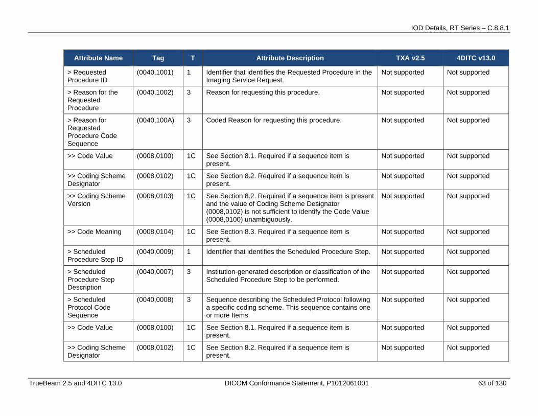
IOD Details, RT Series – C.8.8.1
TrueBeam 2.5 and 4DITC 13.0 DICOM Conformance Statement, P1012061001 63 of 130
Attribute Name Tag T Attribute Description TXA v2.5 4DITC v13.0
> Requested Procedure ID
(0040,1001) 1 Identifier that identifies the Requested Procedure in the Imaging Service Request.
Not supported Not supported
> Reason for the Requested Procedure
(0040,1002) 3 Reason for requesting this procedure. Not supported Not supported
> Reason for Requested Procedure Code Sequence
(0040,100A) 3 Coded Reason for requesting this procedure. Not supported Not supported
>> Code Value (0008,0100) 1C See Section 8.1. Required if a sequence item is present.
Not supported Not supported
>> Coding Scheme Designator
(0008,0102) 1C See Section 8.2. Required if a sequence item is present.
Not supported Not supported
>> Coding Scheme Version
(0008,0103) 1C See Section 8.2. Required if a sequence item is present and the value of Coding Scheme Designator (0008,0102) is not sufficient to identify the Code Value (0008,0100) unambiguously.
Not supported Not supported
>> Code Meaning (0008,0104) 1C See Section 8.3. Required if a sequence item is present.
Not supported Not supported
> Scheduled Procedure Step ID
(0040,0009) 1 Identifier that identifies the Scheduled Procedure Step. Not supported Not supported
> Scheduled Procedure Step Description
(0040,0007) 3 Institution-generated description or classification of the Scheduled Procedure Step to be performed.
Not supported Not supported
> Scheduled Protocol Code Sequence
(0040,0008) 3 Sequence describing the Scheduled Protocol following a specific coding scheme. This sequence contains one or more Items.
Not supported Not supported
>> Code Value (0008,0100) 1C See Section 8.1. Required if a sequence item is present.
Not supported Not supported
>> Coding Scheme Designator
(0008,0102) 1C See Section 8.2. Required if a sequence item is present.
Not supported Not supported

IOD Details, RT Series – C.8.8.1
64 of 130 TrueBeam 2.5 and 4DITC 13.0 DICOM Conformance Statement, P1012061001
Attribute Name Tag T Attribute Description TXA v2.5 4DITC v13.0
>> Coding Scheme Version
(0008,0103) 1C See Section 8.2. Required if a sequence item is present and the value of Coding Scheme Designator (0008,0102) is not sufficient to identify the Code Value (0008,0100) unambiguously.
Not supported Not supported
>> Code Meaning (0008,0104) 1C See Section 8.3. Required if a sequence item is present.
Not supported Not supported
>> Protocol Context Sequence
(0040,0440) 3 Sequence that specifies the context for the Scheduled Protocol Code Sequence Item. One or more items may be included in this sequence.
Not supported Not supported
>>> Code Value (0008,0100) 1C See Section 8.1. Required if a sequence item is present.
Not supported Not supported
>>> Coding Scheme Designator
(0008,0102) 1C See Section 8.2. Required if a sequence item is present.
Not supported Not supported
>>> Coding Scheme Version
(0008,0103) 1C See Section 8.2. Required if a sequence item is present and the value of Coding Scheme Designator (0008,0102) is not sufficient to identify the Code Value (0008,0100) unambiguously.
Not supported Not supported
>>> Code Meaning (0008,0104) 1C See Section 8.3. Required if a sequence item is present.
Not supported Not supported
>>> Content Item Modifier Sequence
(0040,0441) 3 Sequence that specifies modifiers for a Protocol Context Content Item. One or more items may be included in this sequence. See Section C.4.10.1.
Not supported Not supported
>>>> Code Value (0008,0100) 1C See Section 8.1. Required if a sequence item is present.
Not supported Not supported
>>>> Coding Scheme Designator
(0008,0102) 1C See Section 8.2. Required if a sequence item is present.
Not supported Not supported
>>>> Coding Scheme Version
(0008,0103) 1C See Section 8.2. Required if a sequence item is present and the value of Coding Scheme Designator (0008,0102) is not sufficient to identify the Code Value (0008,0100) unambiguously.
Not supported Not supported
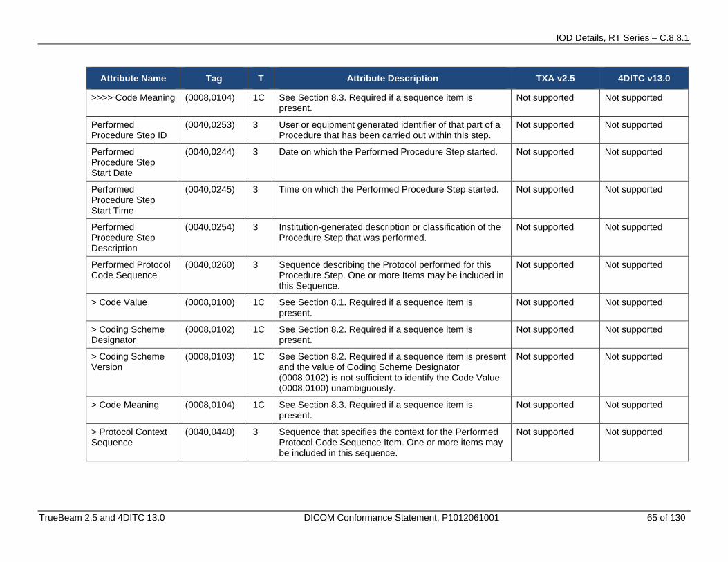
IOD Details, RT Series – C.8.8.1
TrueBeam 2.5 and 4DITC 13.0 DICOM Conformance Statement, P1012061001 65 of 130
Attribute Name Tag T Attribute Description TXA v2.5 4DITC v13.0
>>>> Code Meaning (0008,0104) 1C See Section 8.3. Required if a sequence item is present.
Not supported Not supported
Performed Procedure Step ID
(0040,0253) 3 User or equipment generated identifier of that part of a Procedure that has been carried out within this step.
Not supported Not supported
Performed Procedure Step Start Date
(0040,0244) 3 Date on which the Performed Procedure Step started. Not supported Not supported
Performed Procedure Step Start Time
(0040,0245) 3 Time on which the Performed Procedure Step started. Not supported Not supported
Performed Procedure Step Description
(0040,0254) 3 Institution-generated description or classification of the Procedure Step that was performed.
Not supported Not supported
Performed Protocol Code Sequence
(0040,0260) 3 Sequence describing the Protocol performed for this Procedure Step. One or more Items may be included in this Sequence.
Not supported Not supported
> Code Value (0008,0100) 1C See Section 8.1. Required if a sequence item is present.
Not supported Not supported
> Coding Scheme Designator
(0008,0102) 1C See Section 8.2. Required if a sequence item is present.
Not supported Not supported
> Coding Scheme Version
(0008,0103) 1C See Section 8.2. Required if a sequence item is present and the value of Coding Scheme Designator (0008,0102) is not sufficient to identify the Code Value (0008,0100) unambiguously.
Not supported Not supported
> Code Meaning (0008,0104) 1C See Section 8.3. Required if a sequence item is present.
Not supported Not supported
> Protocol Context Sequence
(0040,0440) 3 Sequence that specifies the context for the Performed Protocol Code Sequence Item. One or more items may be included in this sequence.
Not supported Not supported
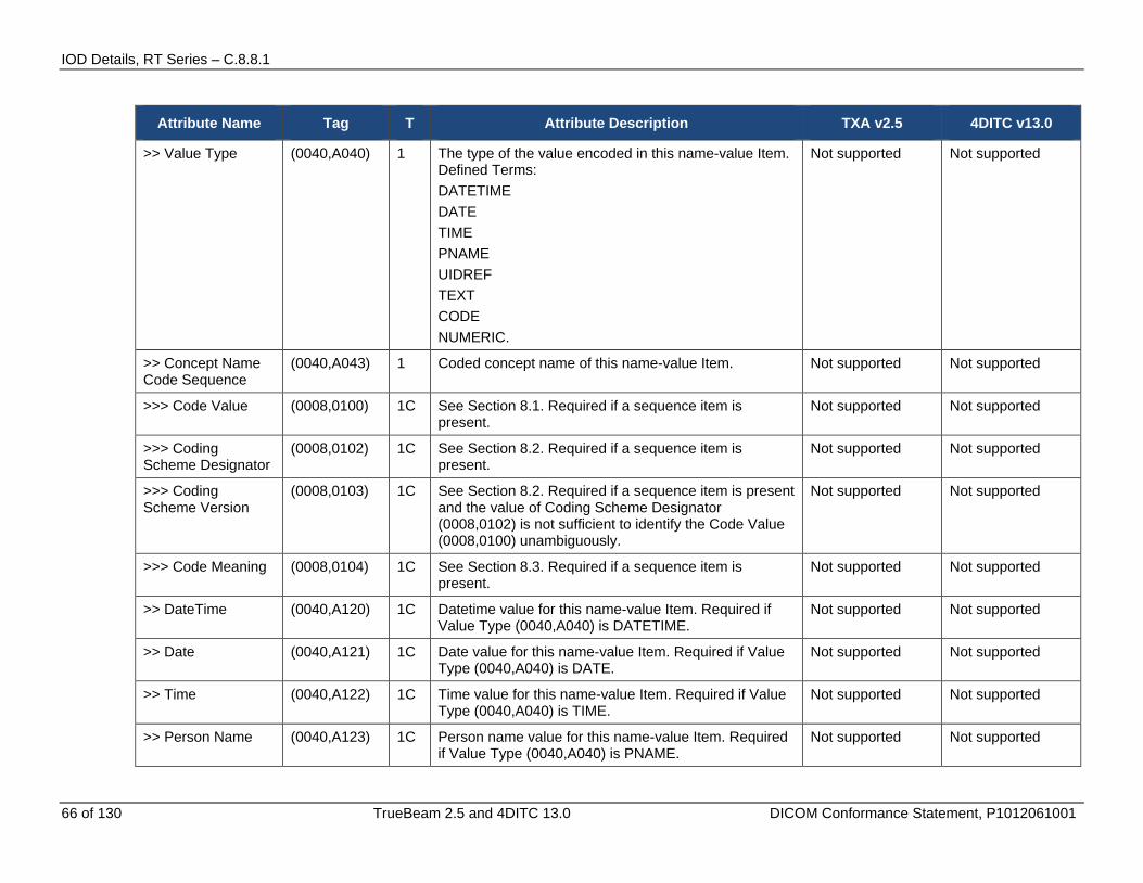
IOD Details, RT Series – C.8.8.1
66 of 130 TrueBeam 2.5 and 4DITC 13.0 DICOM Conformance Statement, P1012061001
Attribute Name Tag T Attribute Description TXA v2.5 4DITC v13.0
>> Value Type (0040,A040) 1 The type of the value encoded in this name-value Item. Defined Terms: DATETIME DATE TIME PNAME UIDREF TEXT CODE NUMERIC.
Not supported Not supported
>> Concept Name Code Sequence
(0040,A043) 1 Coded concept name of this name-value Item. Not supported Not supported
>>> Code Value (0008,0100) 1C See Section 8.1. Required if a sequence item is present.
Not supported Not supported
>>> Coding Scheme Designator
(0008,0102) 1C See Section 8.2. Required if a sequence item is present.
Not supported Not supported
>>> Coding Scheme Version
(0008,0103) 1C See Section 8.2. Required if a sequence item is present and the value of Coding Scheme Designator (0008,0102) is not sufficient to identify the Code Value (0008,0100) unambiguously.
Not supported Not supported
>>> Code Meaning (0008,0104) 1C See Section 8.3. Required if a sequence item is present.
Not supported Not supported
>> DateTime (0040,A120) 1C Datetime value for this name-value Item. Required if Value Type (0040,A040) is DATETIME.
Not supported Not supported
>> Date (0040,A121) 1C Date value for this name-value Item. Required if Value Type (0040,A040) is DATE.
Not supported Not supported
>> Time (0040,A122) 1C Time value for this name-value Item. Required if Value Type (0040,A040) is TIME.
Not supported Not supported
>> Person Name (0040,A123) 1C Person name value for this name-value Item. Required if Value Type (0040,A040) is PNAME.
Not supported Not supported
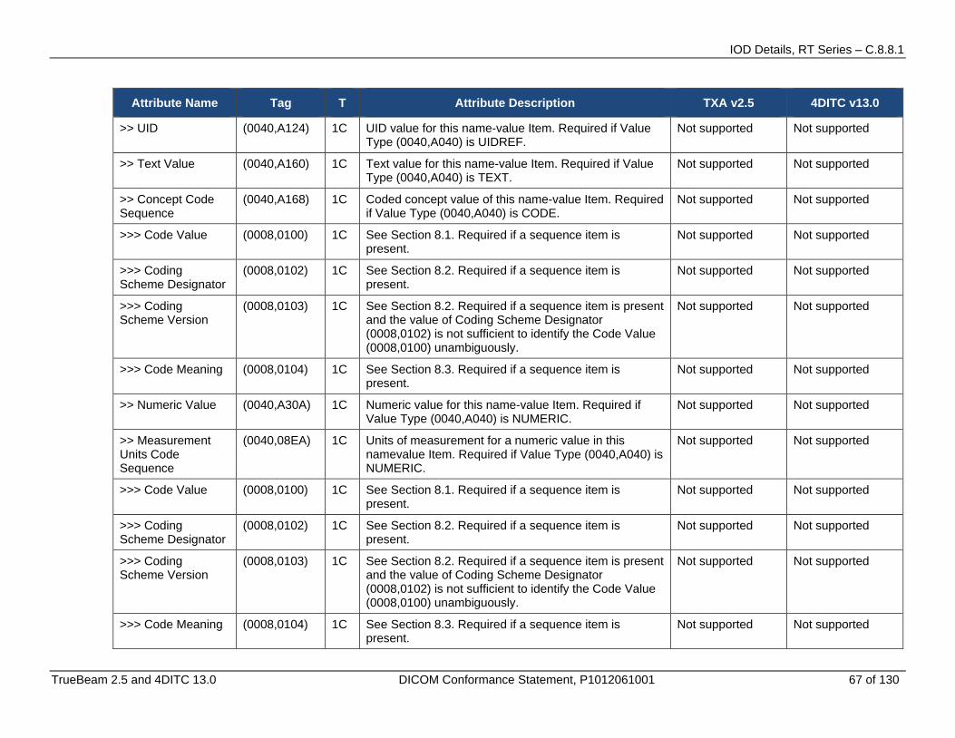
IOD Details, RT Series – C.8.8.1
TrueBeam 2.5 and 4DITC 13.0 DICOM Conformance Statement, P1012061001 67 of 130
Attribute Name Tag T Attribute Description TXA v2.5 4DITC v13.0
>> UID (0040,A124) 1C UID value for this name-value Item. Required if Value Type (0040,A040) is UIDREF.
Not supported Not supported
>> Text Value (0040,A160) 1C Text value for this name-value Item. Required if Value Type (0040,A040) is TEXT.
Not supported Not supported
>> Concept Code Sequence
(0040,A168) 1C Coded concept value of this name-value Item. Required if Value Type (0040,A040) is CODE.
Not supported Not supported
>>> Code Value (0008,0100) 1C See Section 8.1. Required if a sequence item is present.
Not supported Not supported
>>> Coding Scheme Designator
(0008,0102) 1C See Section 8.2. Required if a sequence item is present.
Not supported Not supported
>>> Coding Scheme Version
(0008,0103) 1C See Section 8.2. Required if a sequence item is present and the value of Coding Scheme Designator (0008,0102) is not sufficient to identify the Code Value (0008,0100) unambiguously.
Not supported Not supported
>>> Code Meaning (0008,0104) 1C See Section 8.3. Required if a sequence item is present.
Not supported Not supported
>> Numeric Value (0040,A30A) 1C Numeric value for this name-value Item. Required if Value Type (0040,A040) is NUMERIC.
Not supported Not supported
>> Measurement Units Code Sequence
(0040,08EA) 1C Units of measurement for a numeric value in this namevalue Item. Required if Value Type (0040,A040) is NUMERIC.
Not supported Not supported
>>> Code Value (0008,0100) 1C See Section 8.1. Required if a sequence item is present.
Not supported Not supported
>>> Coding Scheme Designator
(0008,0102) 1C See Section 8.2. Required if a sequence item is present.
Not supported Not supported
>>> Coding Scheme Version
(0008,0103) 1C See Section 8.2. Required if a sequence item is present and the value of Coding Scheme Designator (0008,0102) is not sufficient to identify the Code Value (0008,0100) unambiguously.
Not supported Not supported
>>> Code Meaning (0008,0104) 1C See Section 8.3. Required if a sequence item is present.
Not supported Not supported

IOD Details, RT Series – C.8.8.1
68 of 130 TrueBeam 2.5 and 4DITC 13.0 DICOM Conformance Statement, P1012061001
Attribute Name Tag T Attribute Description TXA v2.5 4DITC v13.0
>> Content Item Modifier Sequence
(0040,0441) 3 Sequence that specifies modifiers for a Protocol Context Content Item. One or more items may be included in this sequence. See Section C.4.10.1.
Not supported Not supported
>>> Value Type (0040,A040) 1 The type of the value encoded in this name-value Item. Defined Terms: DATETIME DATE TIME PNAME UIDREF TEXT CODE NUMERIC.
Not supported Not supported
>>> Concept Name Code Sequence
(0040,A043) 1 Coded concept name of this name-value Item. Not supported Not supported
>>>> Code Value (0008,0100) 1C See Section 8.1. Required if a sequence item is present.
Not supported Not supported
>>>> Coding Scheme Designator
(0008,0102) 1C See Section 8.2. Required if a sequence item is present.
Not supported Not supported
>>>> Coding Scheme Version
(0008,0103) 1C See Section 8.2. Required if a sequence item is present and the value of Coding Scheme Designator (0008,0102) is not sufficient to identify the Code Value (0008,0100) unambiguously.
Not supported Not supported
>>>> Code Meaning (0008,0104) 1C See Section 8.3. Required if a sequence item is present.
Not supported Not supported
>>> DateTime (0040,A120) 1C Datetime value for this name-value Item. Required if Value Type (0040,A040) is DATETIME.
Not supported Not supported
>>> Date (0040,A121) 1C Date value for this name-value Item. Required if Value Type (0040,A040) is DATE.
Not supported Not supported
>>> Time (0040,A122) 1C Time value for this name-value Item. Required if Value Type (0040,A040) is TIME.
Not supported Not supported
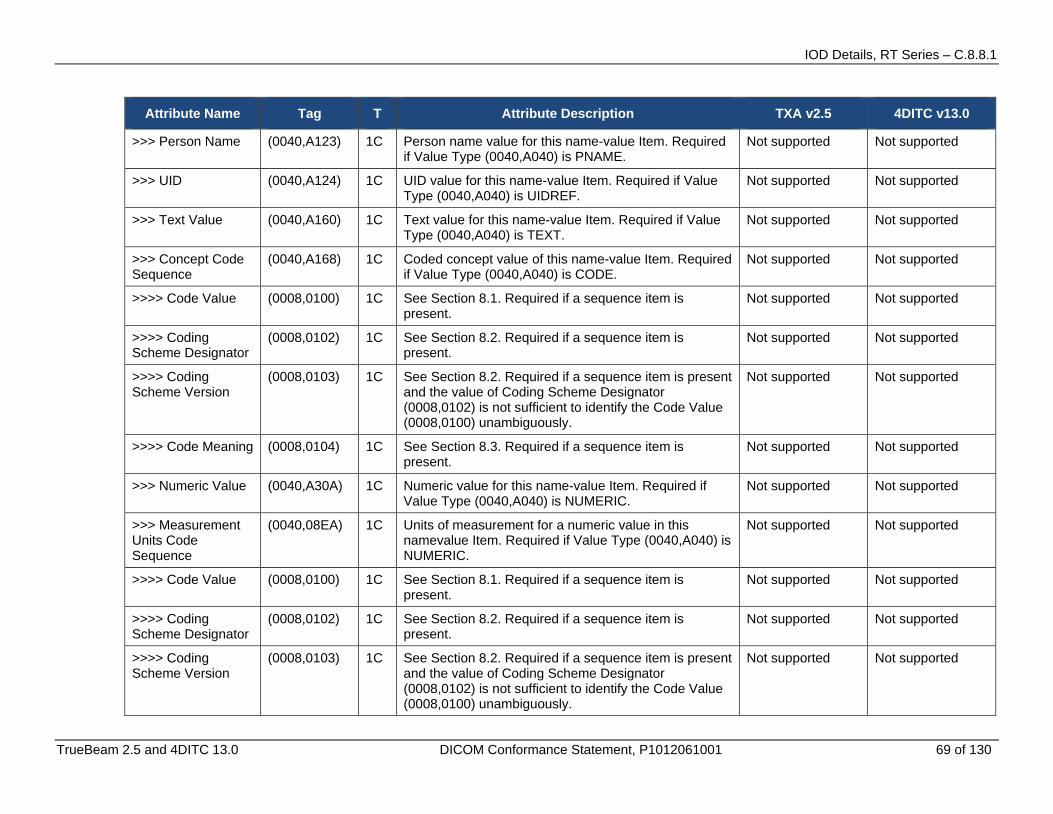
IOD Details, RT Series – C.8.8.1
TrueBeam 2.5 and 4DITC 13.0 DICOM Conformance Statement, P1012061001 69 of 130
Attribute Name Tag T Attribute Description TXA v2.5 4DITC v13.0
>>> Person Name (0040,A123) 1C Person name value for this name-value Item. Required if Value Type (0040,A040) is PNAME.
Not supported Not supported
>>> UID (0040,A124) 1C UID value for this name-value Item. Required if Value Type (0040,A040) is UIDREF.
Not supported Not supported
>>> Text Value (0040,A160) 1C Text value for this name-value Item. Required if Value Type (0040,A040) is TEXT.
Not supported Not supported
>>> Concept Code Sequence
(0040,A168) 1C Coded concept value of this name-value Item. Required if Value Type (0040,A040) is CODE.
Not supported Not supported
>>>> Code Value (0008,0100) 1C See Section 8.1. Required if a sequence item is present.
Not supported Not supported
>>>> Coding Scheme Designator
(0008,0102) 1C See Section 8.2. Required if a sequence item is present.
Not supported Not supported
>>>> Coding Scheme Version
(0008,0103) 1C See Section 8.2. Required if a sequence item is present and the value of Coding Scheme Designator (0008,0102) is not sufficient to identify the Code Value (0008,0100) unambiguously.
Not supported Not supported
>>>> Code Meaning (0008,0104) 1C See Section 8.3. Required if a sequence item is present.
Not supported Not supported
>>> Numeric Value (0040,A30A) 1C Numeric value for this name-value Item. Required if Value Type (0040,A040) is NUMERIC.
Not supported Not supported
>>> Measurement Units Code Sequence
(0040,08EA) 1C Units of measurement for a numeric value in this namevalue Item. Required if Value Type (0040,A040) is NUMERIC.
Not supported Not supported
>>>> Code Value (0008,0100) 1C See Section 8.1. Required if a sequence item is present.
Not supported Not supported
>>>> Coding Scheme Designator
(0008,0102) 1C See Section 8.2. Required if a sequence item is present.
Not supported Not supported
>>>> Coding Scheme Version
(0008,0103) 1C See Section 8.2. Required if a sequence item is present and the value of Coding Scheme Designator (0008,0102) is not sufficient to identify the Code Value (0008,0100) unambiguously.
Not supported Not supported
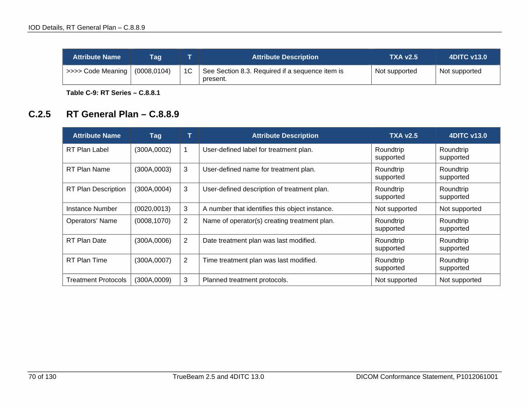
IOD Details, RT General Plan – C.8.8.9
70 of 130 TrueBeam 2.5 and 4DITC 13.0 DICOM Conformance Statement, P1012061001
Attribute Name Tag T Attribute Description TXA v2.5 4DITC v13.0
>>>> Code Meaning (0008,0104) 1C See Section 8.3. Required if a sequence item is present.
Not supported Not supported
Table C-9: RT Series – C.8.8.1
C.2.5 RT General Plan – C.8.8.9
Attribute Name Tag T Attribute Description TXA v2.5 4DITC v13.0
RT Plan Label (300A,0002) 1 User-defined label for treatment plan. Roundtrip supported
Roundtrip supported
RT Plan Name (300A,0003) 3 User-defined name for treatment plan. Roundtrip supported
Roundtrip supported
RT Plan Description (300A,0004) 3 User-defined description of treatment plan. Roundtrip supported
Roundtrip supported
Instance Number (0020,0013) 3 A number that identifies this object instance. Not supported Not supported
Operators’ Name (0008,1070) 2 Name of operator(s) creating treatment plan. Roundtrip supported
Roundtrip supported
RT Plan Date (300A,0006) 2 Date treatment plan was last modified. Roundtrip supported
Roundtrip supported
RT Plan Time (300A,0007) 2 Time treatment plan was last modified. Roundtrip supported
Roundtrip supported
Treatment Protocols (300A,0009) 3 Planned treatment protocols. Not supported Not supported
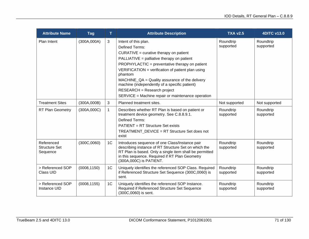
IOD Details, RT General Plan – C.8.8.9
TrueBeam 2.5 and 4DITC 13.0 DICOM Conformance Statement, P1012061001 71 of 130
Attribute Name Tag T Attribute Description TXA v2.5 4DITC v13.0
Plan Intent (300A,000A) 3 Intent of this plan. Defined Terms: CURATIVE = curative therapy on patient PALLIATIVE = palliative therapy on patient PROPHYLACTIC = preventative therapy on patient VERIFICATION = verification of patient plan using phantom MACHINE_QA = Quality assurance of the delivery machine (independently of a specific patient) RESEARCH = Research project SERVICE = Machine repair or maintenance operation
Roundtrip supported
Roundtrip supported
Treatment Sites (300A,000B) 3 Planned treatment sites. Not supported Not supported
RT Plan Geometry (300A,000C) 1 Describes whether RT Plan is based on patient or treatment device geometry. See C.8.8.9.1. Defined Terms: PATIENT = RT Structure Set exists TREATMENT_DEVICE = RT Structure Set does not exist
Roundtrip supported
Roundtrip supported
Referenced Structure Set Sequence
(300C,0060) 1C Introduces sequence of one Class/Instance pair describing instance of RT Structure Set on which the RT Plan is based. Only a single item shall be permitted in this sequence. Required if RT Plan Geometry (300A,000C) is PATIENT.
Roundtrip supported
Roundtrip supported
> Referenced SOP Class UID
(0008,1150) 1C Uniquely identifies the referenced SOP Class. Required if Referenced Structure Set Sequence (300C,0060) is sent.
Roundtrip supported
Roundtrip supported
> Referenced SOP Instance UID
(0008,1155) 1C Uniquely identifies the referenced SOP Instance. Required if Referenced Structure Set Sequence (300C,0060) is sent.
Roundtrip supported
Roundtrip supported

IOD Details, RT General Plan – C.8.8.9
72 of 130 TrueBeam 2.5 and 4DITC 13.0 DICOM Conformance Statement, P1012061001
Attribute Name Tag T Attribute Description TXA v2.5 4DITC v13.0
Referenced Dose Sequence
(300C,0080) 3 Introduces sequence of related SOP Class/Instance pairs describing related instances of RT Dose (for grids and named/unnamed point doses). One or more items may be included in this sequence. See Note 1.
Not supported Not supported
> Referenced SOP Class UID
(0008,1150) 1C Uniquely identifies the referenced SOP Class. Required if Referenced RT Dose Sequence (300C,0080) is sent.
Not supported Not supported
> Referenced SOP Instance UID
(0008,1155) 1C Uniquely identifies the referenced SOP Instance. Required if Referenced RT Dose Sequence (300C,0080) is sent.
Not supported Not supported
Referenced RT Plan Sequence
(300C,0002) 3 Introduces sequence of related SOP Class/Instance pairs describing related instances of RT Plan. One or more items may be included in this sequence.
Roundtrip supported
Roundtrip supported
> Referenced SOP Class UID
(0008,1150) 1C Uniquely identifies the referenced SOP Class. Required if Referenced RT Plan Sequence (300C,0002) is sent.
Roundtrip supported
Roundtrip supported
> Referenced SOP Instance UID
(0008,1155) 1C Uniquely identifies the referenced SOP Instance. Required if Referenced RT Plan Sequence (300C,0002) is sent.
Roundtrip supported
Roundtrip supported
> RT Plan Relationship
(300A,0055) 1C Relationship of referenced plan with respect to current plan. Required if Referenced RT Plan Sequence (300C,0002) is sent. Defined Terms: PRIOR = plan delivered prior to current treatment ALTERNATIVE = alternative plan prepared for current treatment PREDECESSOR = plan used in derivation of current plan VERIFIED_PLAN = plan which is verified using the current plan. This value shall only be used if Plan Intent (300A,000A) is present and has a value of VERIFICATION.
Roundtrip supported
Roundtrip supported
Beam Line Data Table Version
(300B,1008) 3 Version Number that is set for Look-up Table (and/or for each beam tune in Look-up Table in future)
Not supported Not supported
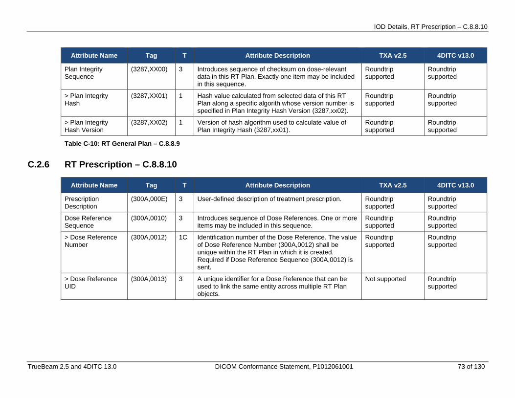
IOD Details, RT Prescription – C.8.8.10
TrueBeam 2.5 and 4DITC 13.0 DICOM Conformance Statement, P1012061001 73 of 130
Attribute Name Tag T Attribute Description TXA v2.5 4DITC v13.0
Plan Integrity Sequence
(3287,XX00) 3 Introduces sequence of checksum on dose-relevant data in this RT Plan. Exactly one item may be included in this sequence.
Roundtrip supported
Roundtrip supported
> Plan Integrity Hash
(3287,XX01) 1 Hash value calculated from selected data of this RT Plan along a specific algorith whose version number is specified in Plan Integrity Hash Version (3287,xx02).
Roundtrip supported
Roundtrip supported
> Plan Integrity Hash Version
(3287,XX02) 1 Version of hash algorithm used to calculate value of Plan Integrity Hash (3287,xx01).
Roundtrip supported
Roundtrip supported
Table C-10: RT General Plan – C.8.8.9
C.2.6 RT Prescription – C.8.8.10
Attribute Name Tag T Attribute Description TXA v2.5 4DITC v13.0
Prescription Description
(300A,000E) 3 User-defined description of treatment prescription. Roundtrip supported
Roundtrip supported
Dose Reference Sequence
(300A,0010) 3 Introduces sequence of Dose References. One or more items may be included in this sequence.
Roundtrip supported
Roundtrip supported
> Dose Reference Number
(300A,0012) 1C Identification number of the Dose Reference. The value of Dose Reference Number (300A,0012) shall be unique within the RT Plan in which it is created. Required if Dose Reference Sequence (300A,0012) is sent.
Roundtrip supported
Roundtrip supported
> Dose Reference UID
(300A,0013) 3 A unique identifier for a Dose Reference that can be used to link the same entity across multiple RT Plan objects.
Not supported Roundtrip supported
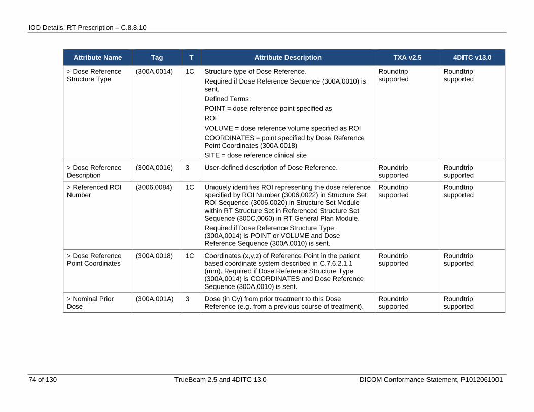
IOD Details, RT Prescription – C.8.8.10
74 of 130 TrueBeam 2.5 and 4DITC 13.0 DICOM Conformance Statement, P1012061001
Attribute Name Tag T Attribute Description TXA v2.5 4DITC v13.0
> Dose Reference Structure Type
(300A,0014) 1C Structure type of Dose Reference. Required if Dose Reference Sequence (300A,0010) is sent. Defined Terms: POINT = dose reference point specified as ROI VOLUME = dose reference volume specified as ROI COORDINATES = point specified by Dose Reference Point Coordinates (300A,0018) SITE = dose reference clinical site
Roundtrip supported
Roundtrip supported
> Dose Reference Description
(300A,0016) 3 User-defined description of Dose Reference. Roundtrip supported
Roundtrip supported
> Referenced ROI Number
(3006,0084) 1C Uniquely identifies ROI representing the dose reference specified by ROI Number (3006,0022) in Structure Set ROI Sequence (3006,0020) in Structure Set Module within RT Structure Set in Referenced Structure Set Sequence (300C,0060) in RT General Plan Module. Required if Dose Reference Structure Type (300A,0014) is POINT or VOLUME and Dose Reference Sequence (300A,0010) is sent.
Roundtrip supported
Roundtrip supported
> Dose Reference Point Coordinates
(300A,0018) 1C Coordinates (x,y,z) of Reference Point in the patient based coordinate system described in C.7.6.2.1.1 (mm). Required if Dose Reference Structure Type (300A,0014) is COORDINATES and Dose Reference Sequence (300A,0010) is sent.
Roundtrip supported
Roundtrip supported
> Nominal Prior Dose
(300A,001A) 3 Dose (in Gy) from prior treatment to this Dose Reference (e.g. from a previous course of treatment).
Roundtrip supported
Roundtrip supported

IOD Details, RT Prescription – C.8.8.10
TrueBeam 2.5 and 4DITC 13.0 DICOM Conformance Statement, P1012061001 75 of 130
Attribute Name Tag T Attribute Description TXA v2.5 4DITC v13.0
> Dose Reference Type
(300A,0020) 1C Type of Dose Reference. Required if Dose Reference Sequence (300A,0010) is sent. Defined Terms: TARGET = treatment target (corresponding to GTV, PTV, or CTV in ICRU50) ORGAN_AT_RISK = Organ at Risk (as defined in ICRU50)
Roundtrip supported
Roundtrip supported
> Constraint Weight (300A,0021) 3 Relative importance of satisfying constraint, where high values represent more important constraints.
Roundtrip supported
Roundtrip supported
> Delivery Warning Dose
(300A,0022) 3 The dose (in Gy) which when reached or exceeded should cause some action to be taken.
Roundtrip supported
Roundtrip supported
> Delivery Maximum Dose
(300A,0023) 3 The maximum dose (in Gy) which can be delivered to the dose reference.
Roundtrip supported
Roundtrip supported
> Target Minimum Dose
(300A,0025) 3 Minimum permitted dose (in Gy) to Dose Reference if Dose Reference Type (300A,0020) is TARGET.
Not supported Roundtrip supported
> Target Prescription Dose
(300A,0026) 3 Prescribed dose (in Gy) to Dose Reference if Dose Reference Type (300A,0020) is TARGET.
Roundtrip supported
Roundtrip supported
> Target Maximum Dose
(300A,0027) 3 Maximum permitted dose (in Gy) to Dose Reference if Dose Reference Type (300A,0020) is TARGET.
Roundtrip supported
Roundtrip supported
> Referenced Patient Volume Id
(3267,XX00) 3 *** not supported **
Not supported
> Target Underdose Volume Fraction
(300A,0028) 3 Maximum permitted fraction (in percent) of Target to receive less than the Target Prescription Dose if Dose Reference Type (300A,0020) is TARGET and Dose Reference Structure Type (300A,0014) is VOLUME. See C.8.8.10.1.
Not supported Not supported
> Organ at Risk Full-volume Dose
(300A,002A) 3 Maximum dose (in Gy) to entire Dose Reference if Dose Reference Type (300A,0020) is ORGAN_AT_RISK and Dose Reference Structure Type (300A,0014) is VOLUME.
Not supported Not supported
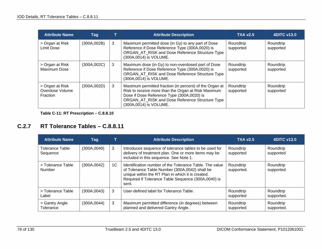
IOD Details, RT Tolerance Tables – C.8.8.11
76 of 130 TrueBeam 2.5 and 4DITC 13.0 DICOM Conformance Statement, P1012061001
Attribute Name Tag T Attribute Description TXA v2.5 4DITC v13.0
> Organ at Risk Limit Dose
(300A,002B) 3 Maximum permitted dose (in Gy) to any part of Dose Reference if Dose Reference Type (300A,0020) is ORGAN_AT_RISK and Dose Reference Structure Type (300A,0014) is VOLUME.
Roundtrip supported
Roundtrip supported
> Organ at Risk Maximum Dose
(300A,002C) 3 Maximum dose (in Gy) to non-overdosed part of Dose Reference if Dose Reference Type (300A,0020) is ORGAN_AT_RISK and Dose Reference Structure Type (300A,0014) is VOLUME.
Roundtrip supported
Roundtrip supported
> Organ at Risk Overdose Volume Fraction
(300A,002D) 3 Maximum permitted fraction (in percent) of the Organ at Risk to receive more than the Organ at Risk Maximum Dose if Dose Reference Type (300A,0020) is ORGAN_AT_RISK and Dose Reference Structure Type (300A,0014) is VOLUME.
Roundtrip supported
Roundtrip supported
Table C-11: RT Prescription – C.8.8.10
C.2.7 RT Tolerance Tables – C.8.8.11
Attribute Name Tag T Attribute Description TXA v2.5 4DITC v13.0
Tolerance Table Sequence
(300A,0040) 3 Introduces sequence of tolerance tables to be used for delivery of treatment plan. One or more items may be included in this sequence. See Note 1.
Roundtrip supported
Roundtrip supported
> Tolerance Table Number
(300A,0042) 1C Identification number of the Tolerance Table. The value of Tolerance Table Number (300A,0042) shall be unique within the RT Plan in which it is created. Required if Tolerance Table Sequence (300A,0040) is sent.
Roundtrip supported.
Roundtrip supported.
> Tolerance Table Label
(300A,0043) 3 User-defined label for Tolerance Table. Roundtrip supported
Roundtrip supported.
> Gantry Angle Tolerance
(300A,0044) 3 Maximum permitted difference (in degrees) between planned and delivered Gantry Angle.
Roundtrip supported
Roundtrip supported.
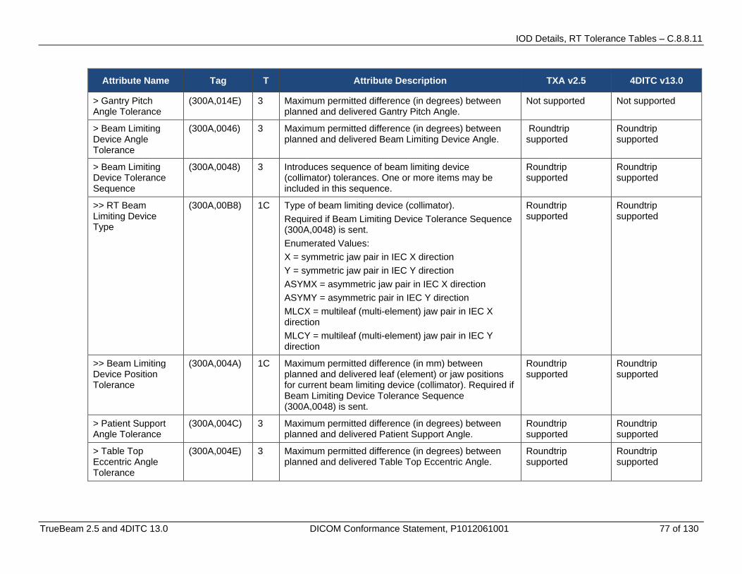
IOD Details, RT Tolerance Tables – C.8.8.11
TrueBeam 2.5 and 4DITC 13.0 DICOM Conformance Statement, P1012061001 77 of 130
Attribute Name Tag T Attribute Description TXA v2.5 4DITC v13.0
> Gantry Pitch Angle Tolerance
(300A,014E) 3 Maximum permitted difference (in degrees) between planned and delivered Gantry Pitch Angle.
Not supported Not supported
> Beam Limiting Device Angle Tolerance
(300A,0046) 3 Maximum permitted difference (in degrees) between planned and delivered Beam Limiting Device Angle.
Roundtrip supported
Roundtrip supported
> Beam Limiting Device Tolerance Sequence
(300A,0048) 3 Introduces sequence of beam limiting device (collimator) tolerances. One or more items may be included in this sequence.
Roundtrip supported
Roundtrip supported
>> RT Beam Limiting Device Type
(300A,00B8) 1C Type of beam limiting device (collimator). Required if Beam Limiting Device Tolerance Sequence (300A,0048) is sent. Enumerated Values: X = symmetric jaw pair in IEC X direction Y = symmetric jaw pair in IEC Y direction ASYMX = asymmetric jaw pair in IEC X direction ASYMY = asymmetric pair in IEC Y direction MLCX = multileaf (multi-element) jaw pair in IEC X direction MLCY = multileaf (multi-element) jaw pair in IEC Y direction
Roundtrip supported
Roundtrip supported
>> Beam Limiting Device Position Tolerance
(300A,004A) 1C Maximum permitted difference (in mm) between planned and delivered leaf (element) or jaw positions for current beam limiting device (collimator). Required if Beam Limiting Device Tolerance Sequence (300A,0048) is sent.
Roundtrip supported
Roundtrip supported
> Patient Support Angle Tolerance
(300A,004C) 3 Maximum permitted difference (in degrees) between planned and delivered Patient Support Angle.
Roundtrip supported
Roundtrip supported
> Table Top Eccentric Angle Tolerance
(300A,004E) 3 Maximum permitted difference (in degrees) between planned and delivered Table Top Eccentric Angle.
Roundtrip supported
Roundtrip supported

IOD Details, RT Patient Setup – C.8.8.12
78 of 130 TrueBeam 2.5 and 4DITC 13.0 DICOM Conformance Statement, P1012061001
Attribute Name Tag T Attribute Description TXA v2.5 4DITC v13.0
> Table Top Pitch Angle Tolerance
(300A,004F) 3 Maximum permitted difference (in degrees) between the planned and delivered Table Top Pitch Angle.
Beam will be valid if the tag is not available or has any value. This value will be read and ignored.
Not supported
> Table Top Roll Angle Tolerance
(300A,0050) 3 Maximum permitted difference (in degrees) between the planned and delivered Table Top Roll Angle.
Beam will be valid if the tag is not available or has any value. This value will be read and ignored.
Not supported
> Table Top Vertical Position Tolerance
(300A,0051) 3 Maximum permitted difference (in mm) between planned and delivered Table Top Vertical Position.
Roundtrip supported
Roundtrip supported
> Table Top Longitudinal Position Tolerance
(300A,0052) 3 Maximum permitted difference (in mm) between planned and delivered Table Top Longitudinal Position.
Roundtrip supported
Roundtrip supported
> Table Top Lateral Position Tolerance
(300A,0053) 3 Maximum permitted difference (in mm) between planned and delivered Table Top Lateral Position.
Roundtrip supported
Roundtrip supported
Table C-12: RT Tolerance Tables – C.8.8.11
C.2.8 RT Patient Setup – C.8.8.12
Attribute Name Tag T Attribute Description TXA v2.5 4DITC v13.0
Patient Setup Sequence
(300A,0180) 1 Introduces sequence of patient setup data for current plan. One or more items may be included in this sequence.
Roundtrip supported
Roundtrip supported
> Patient Setup Number
(300A,0182) 1 Identification number of the Patient Setup. The value of Patient Setup Number (300A,0182) shall be unique within the RT Plan in which it is created.
Roundtrip supported
Roundtrip supported
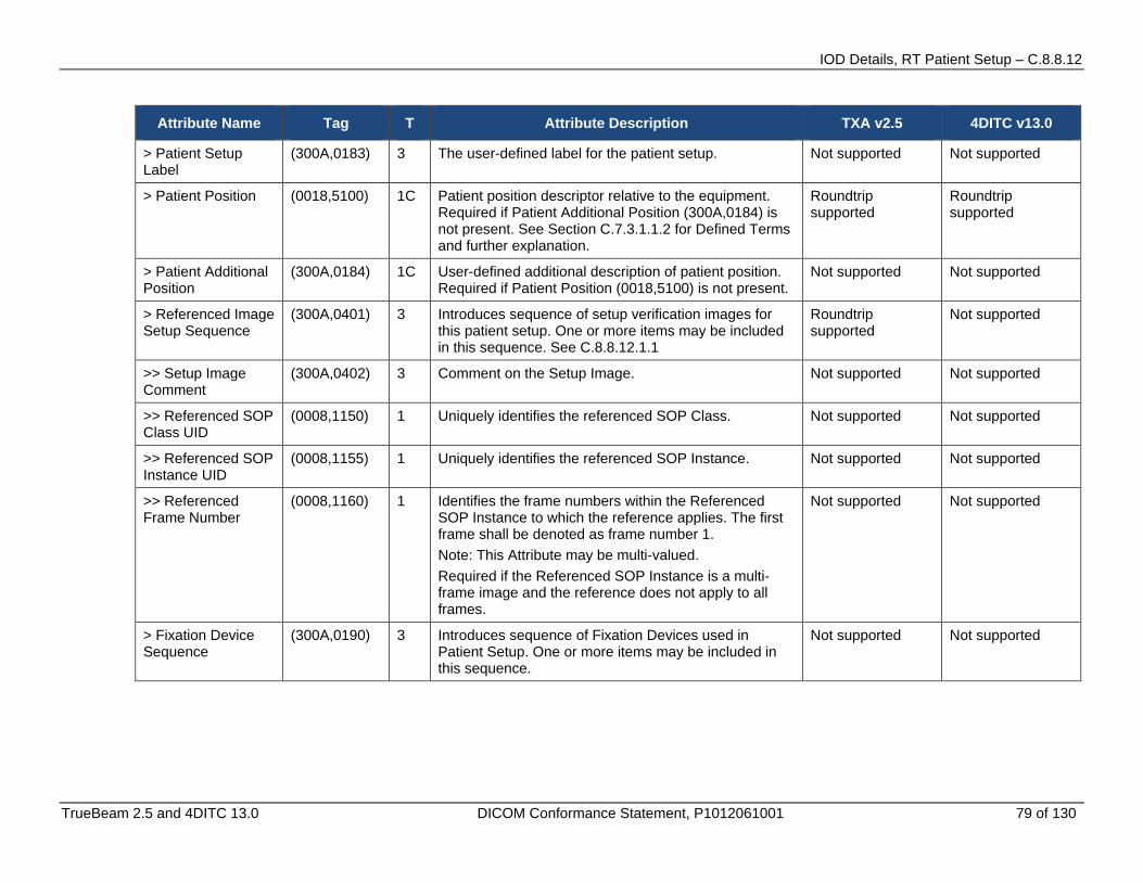
IOD Details, RT Patient Setup – C.8.8.12
TrueBeam 2.5 and 4DITC 13.0 DICOM Conformance Statement, P1012061001 79 of 130
Attribute Name Tag T Attribute Description TXA v2.5 4DITC v13.0
> Patient Setup Label
(300A,0183) 3 The user-defined label for the patient setup. Not supported Not supported
> Patient Position (0018,5100) 1C Patient position descriptor relative to the equipment. Required if Patient Additional Position (300A,0184) is not present. See Section C.7.3.1.1.2 for Defined Terms and further explanation.
Roundtrip supported
Roundtrip supported
> Patient Additional Position
(300A,0184) 1C User-defined additional description of patient position. Required if Patient Position (0018,5100) is not present.
Not supported Not supported
> Referenced Image Setup Sequence
(300A,0401) 3 Introduces sequence of setup verification images for this patient setup. One or more items may be included in this sequence. See C.8.8.12.1.1
Roundtrip supported
Not supported
>> Setup Image Comment
(300A,0402) 3 Comment on the Setup Image. Not supported Not supported
>> Referenced SOP Class UID
(0008,1150) 1 Uniquely identifies the referenced SOP Class. Not supported Not supported
>> Referenced SOP Instance UID
(0008,1155) 1 Uniquely identifies the referenced SOP Instance. Not supported Not supported
>> Referenced Frame Number
(0008,1160) 1 Identifies the frame numbers within the Referenced SOP Instance to which the reference applies. The first frame shall be denoted as frame number 1. Note: This Attribute may be multi-valued. Required if the Referenced SOP Instance is a multi-frame image and the reference does not apply to all frames.
Not supported Not supported
> Fixation Device Sequence
(300A,0190) 3 Introduces sequence of Fixation Devices used in Patient Setup. One or more items may be included in this sequence.
Not supported Not supported
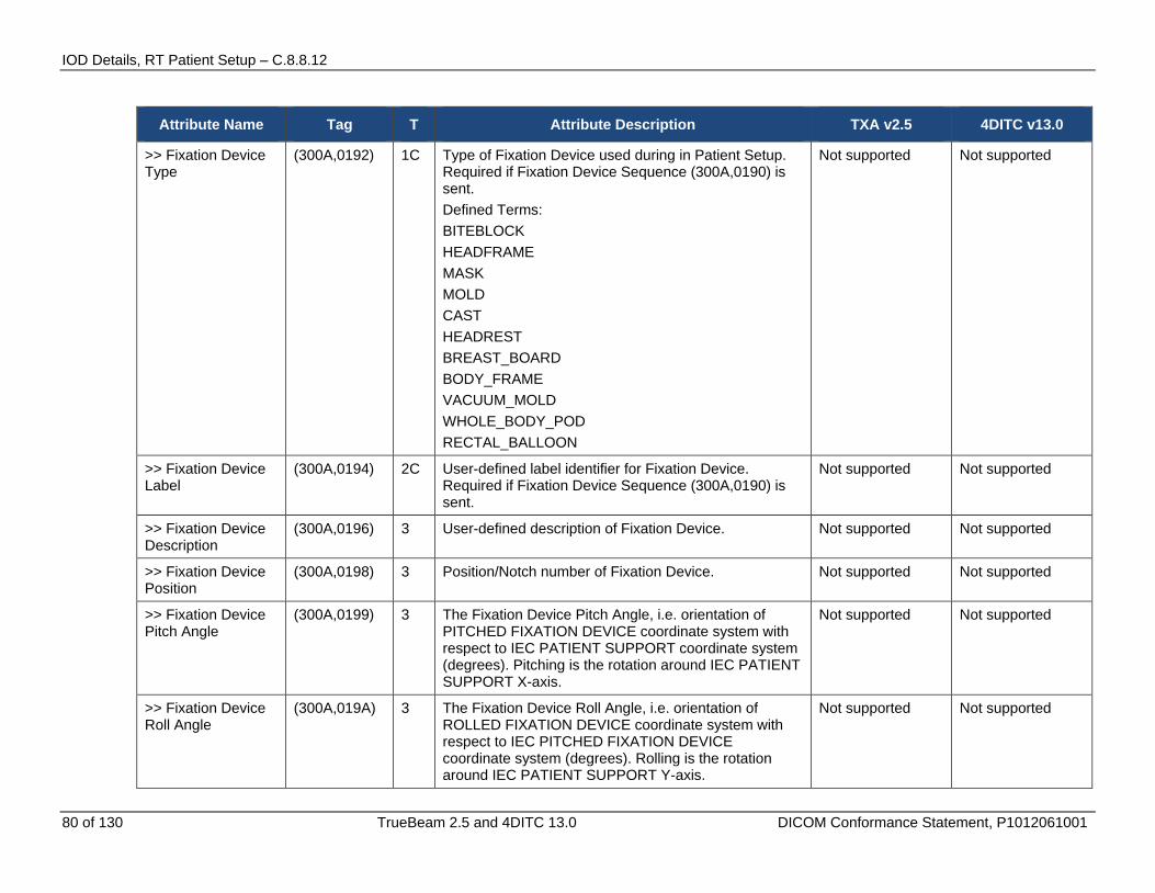
IOD Details, RT Patient Setup – C.8.8.12
80 of 130 TrueBeam 2.5 and 4DITC 13.0 DICOM Conformance Statement, P1012061001
Attribute Name Tag T Attribute Description TXA v2.5 4DITC v13.0
>> Fixation Device Type
(300A,0192) 1C Type of Fixation Device used during in Patient Setup. Required if Fixation Device Sequence (300A,0190) is sent. Defined Terms: BITEBLOCK HEADFRAME MASK MOLD CAST HEADREST BREAST_BOARD BODY_FRAME VACUUM_MOLD WHOLE_BODY_POD RECTAL_BALLOON
Not supported Not supported
>> Fixation Device Label
(300A,0194) 2C User-defined label identifier for Fixation Device. Required if Fixation Device Sequence (300A,0190) is sent.
Not supported Not supported
>> Fixation Device Description
(300A,0196) 3 User-defined description of Fixation Device. Not supported Not supported
>> Fixation Device Position
(300A,0198) 3 Position/Notch number of Fixation Device. Not supported Not supported
>> Fixation Device Pitch Angle
(300A,0199) 3 The Fixation Device Pitch Angle, i.e. orientation of PITCHED FIXATION DEVICE coordinate system with respect to IEC PATIENT SUPPORT coordinate system (degrees). Pitching is the rotation around IEC PATIENT SUPPORT X-axis.
Not supported Not supported
>> Fixation Device Roll Angle
(300A,019A) 3 The Fixation Device Roll Angle, i.e. orientation of ROLLED FIXATION DEVICE coordinate system with respect to IEC PITCHED FIXATION DEVICE coordinate system (degrees). Rolling is the rotation around IEC PATIENT SUPPORT Y-axis.
Not supported Not supported
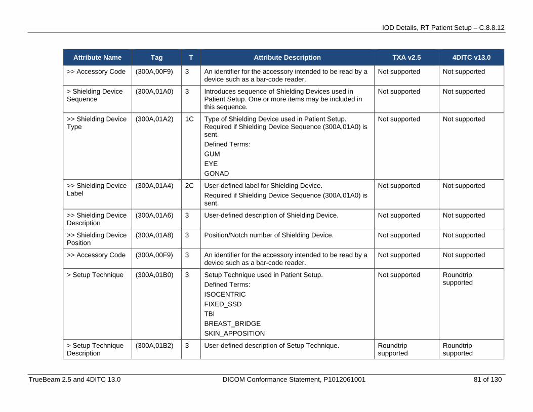
IOD Details, RT Patient Setup – C.8.8.12
TrueBeam 2.5 and 4DITC 13.0 DICOM Conformance Statement, P1012061001 81 of 130
Attribute Name Tag T Attribute Description TXA v2.5 4DITC v13.0
>> Accessory Code (300A,00F9) 3 An identifier for the accessory intended to be read by a device such as a bar-code reader.
Not supported Not supported
> Shielding Device Sequence
(300A,01A0) 3 Introduces sequence of Shielding Devices used in Patient Setup. One or more items may be included in this sequence.
Not supported Not supported
>> Shielding Device Type
(300A,01A2) 1C Type of Shielding Device used in Patient Setup. Required if Shielding Device Sequence (300A,01A0) is sent. Defined Terms: GUM EYE GONAD
Not supported Not supported
>> Shielding Device Label
(300A,01A4) 2C User-defined label for Shielding Device. Required if Shielding Device Sequence (300A,01A0) is sent.
Not supported Not supported
>> Shielding Device Description
(300A,01A6) 3 User-defined description of Shielding Device. Not supported Not supported
>> Shielding Device Position
(300A,01A8) 3 Position/Notch number of Shielding Device. Not supported Not supported
>> Accessory Code (300A,00F9) 3 An identifier for the accessory intended to be read by a device such as a bar-code reader.
Not supported Not supported
> Setup Technique (300A,01B0) 3 Setup Technique used in Patient Setup. Defined Terms: ISOCENTRIC FIXED_SSD TBI BREAST_BRIDGE SKIN_APPOSITION
Not supported Roundtrip supported
> Setup Technique Description
(300A,01B2) 3 User-defined description of Setup Technique. Roundtrip supported
Roundtrip supported
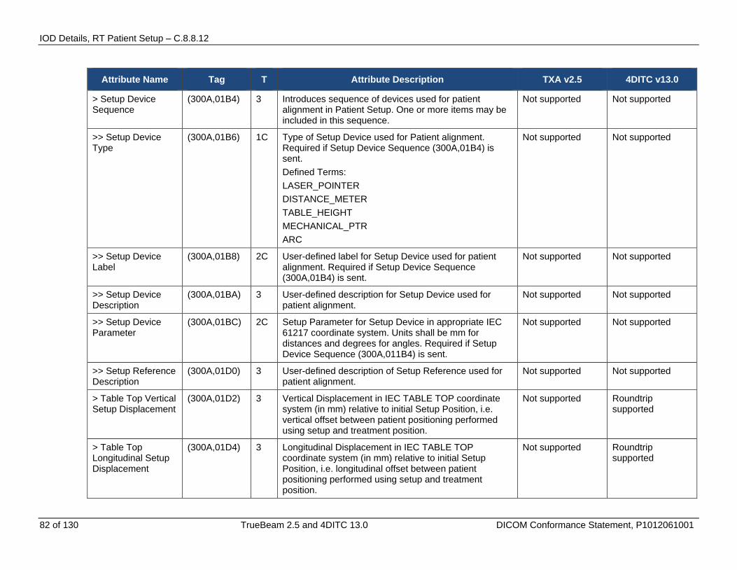
IOD Details, RT Patient Setup – C.8.8.12
82 of 130 TrueBeam 2.5 and 4DITC 13.0 DICOM Conformance Statement, P1012061001
Attribute Name Tag T Attribute Description TXA v2.5 4DITC v13.0
> Setup Device Sequence
(300A,01B4) 3 Introduces sequence of devices used for patient alignment in Patient Setup. One or more items may be included in this sequence.
Not supported Not supported
>> Setup Device Type
(300A,01B6) 1C Type of Setup Device used for Patient alignment. Required if Setup Device Sequence (300A,01B4) is sent. Defined Terms: LASER_POINTER DISTANCE_METER TABLE_HEIGHT MECHANICAL_PTR ARC
Not supported Not supported
>> Setup Device Label
(300A,01B8) 2C User-defined label for Setup Device used for patient alignment. Required if Setup Device Sequence (300A,01B4) is sent.
Not supported Not supported
>> Setup Device Description
(300A,01BA) 3 User-defined description for Setup Device used for patient alignment.
Not supported Not supported
>> Setup Device Parameter
(300A,01BC) 2C Setup Parameter for Setup Device in appropriate IEC 61217 coordinate system. Units shall be mm for distances and degrees for angles. Required if Setup Device Sequence (300A,011B4) is sent.
Not supported Not supported
>> Setup Reference Description
(300A,01D0) 3 User-defined description of Setup Reference used for patient alignment.
Not supported Not supported
> Table Top Vertical Setup Displacement
(300A,01D2) 3 Vertical Displacement in IEC TABLE TOP coordinate system (in mm) relative to initial Setup Position, i.e. vertical offset between patient positioning performed using setup and treatment position.
Not supported Roundtrip supported
> Table Top Longitudinal Setup Displacement
(300A,01D4) 3 Longitudinal Displacement in IEC TABLE TOP coordinate system (in mm) relative to initial Setup Position, i.e. longitudinal offset between patient positioning performed using setup and treatment position.
Not supported Roundtrip supported
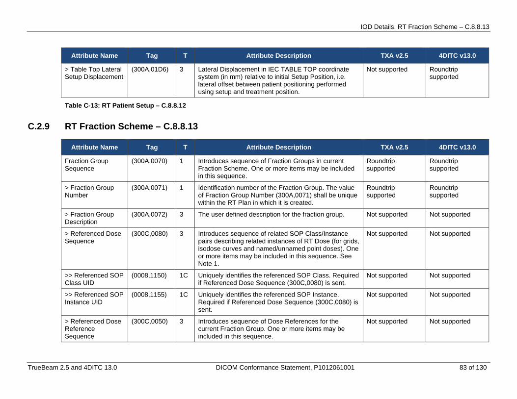
IOD Details, RT Fraction Scheme – C.8.8.13
TrueBeam 2.5 and 4DITC 13.0 DICOM Conformance Statement, P1012061001 83 of 130
Attribute Name Tag T Attribute Description TXA v2.5 4DITC v13.0
> Table Top Lateral Setup Displacement
(300A,01D6) 3 Lateral Displacement in IEC TABLE TOP coordinate system (in mm) relative to initial Setup Position, i.e. lateral offset between patient positioning performed using setup and treatment position.
Not supported Roundtrip supported
Table C-13: RT Patient Setup – C.8.8.12
C.2.9 RT Fraction Scheme – C.8.8.13
Attribute Name Tag T Attribute Description TXA v2.5 4DITC v13.0
Fraction Group Sequence
(300A,0070) 1 Introduces sequence of Fraction Groups in current Fraction Scheme. One or more items may be included in this sequence.
Roundtrip supported
Roundtrip supported
> Fraction Group Number
(300A,0071) 1 Identification number of the Fraction Group. The value of Fraction Group Number (300A,0071) shall be unique within the RT Plan in which it is created.
Roundtrip supported
Roundtrip supported
> Fraction Group Description
(300A,0072) 3 The user defined description for the fraction group. Not supported Not supported
> Referenced Dose Sequence
(300C,0080) 3 Introduces sequence of related SOP Class/Instance pairs describing related instances of RT Dose (for grids, isodose curves and named/unnamed point doses). One or more items may be included in this sequence. See Note 1.
Not supported Not supported
>> Referenced SOP Class UID
(0008,1150) 1C Uniquely identifies the referenced SOP Class. Required if Referenced Dose Sequence (300C,0080) is sent.
Not supported Not supported
>> Referenced SOP Instance UID
(0008,1155) 1C Uniquely identifies the referenced SOP Instance. Required if Referenced Dose Sequence (300C,0080) is sent.
Not supported Not supported
> Referenced Dose Reference Sequence
(300C,0050) 3 Introduces sequence of Dose References for the current Fraction Group. One or more items may be included in this sequence.
Not supported Not supported
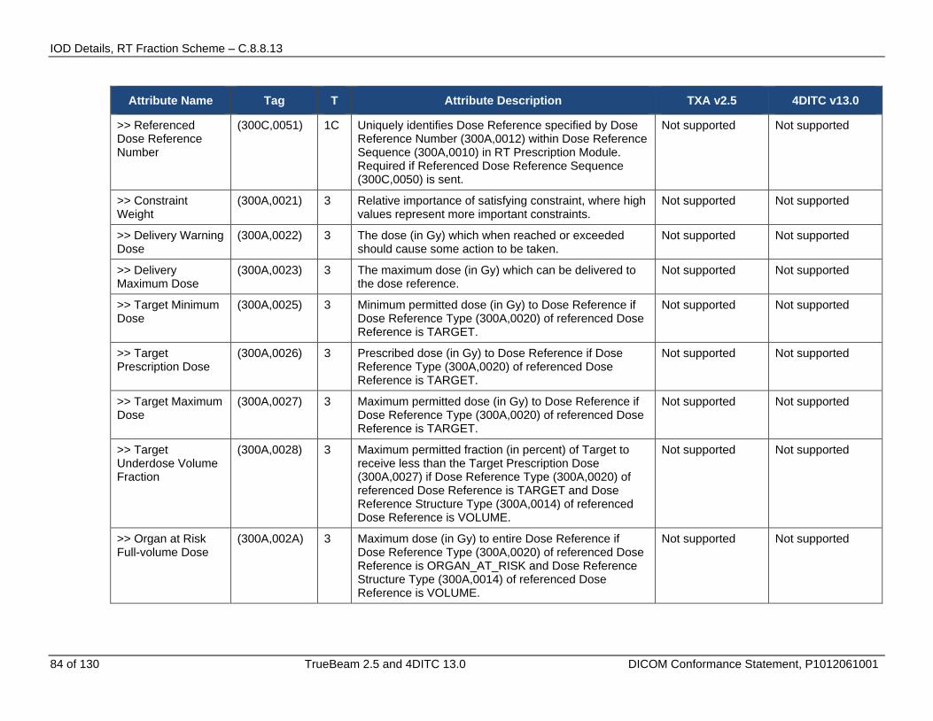
IOD Details, RT Fraction Scheme – C.8.8.13
84 of 130 TrueBeam 2.5 and 4DITC 13.0 DICOM Conformance Statement, P1012061001
Attribute Name Tag T Attribute Description TXA v2.5 4DITC v13.0
>> Referenced Dose Reference Number
(300C,0051) 1C Uniquely identifies Dose Reference specified by Dose Reference Number (300A,0012) within Dose Reference Sequence (300A,0010) in RT Prescription Module. Required if Referenced Dose Reference Sequence (300C,0050) is sent.
Not supported Not supported
>> Constraint Weight
(300A,0021) 3 Relative importance of satisfying constraint, where high values represent more important constraints.
Not supported Not supported
>> Delivery Warning Dose
(300A,0022) 3 The dose (in Gy) which when reached or exceeded should cause some action to be taken.
Not supported Not supported
>> Delivery Maximum Dose
(300A,0023) 3 The maximum dose (in Gy) which can be delivered to the dose reference.
Not supported Not supported
>> Target Minimum Dose
(300A,0025) 3 Minimum permitted dose (in Gy) to Dose Reference if Dose Reference Type (300A,0020) of referenced Dose Reference is TARGET.
Not supported Not supported
>> Target Prescription Dose
(300A,0026) 3 Prescribed dose (in Gy) to Dose Reference if Dose Reference Type (300A,0020) of referenced Dose Reference is TARGET.
Not supported Not supported
>> Target Maximum Dose
(300A,0027) 3 Maximum permitted dose (in Gy) to Dose Reference if Dose Reference Type (300A,0020) of referenced Dose Reference is TARGET.
Not supported Not supported
>> Target Underdose Volume Fraction
(300A,0028) 3 Maximum permitted fraction (in percent) of Target to receive less than the Target Prescription Dose (300A,0027) if Dose Reference Type (300A,0020) of referenced Dose Reference is TARGET and Dose Reference Structure Type (300A,0014) of referenced Dose Reference is VOLUME.
Not supported Not supported
>> Organ at Risk Full-volume Dose
(300A,002A) 3 Maximum dose (in Gy) to entire Dose Reference if Dose Reference Type (300A,0020) of referenced Dose Reference is ORGAN_AT_RISK and Dose Reference Structure Type (300A,0014) of referenced Dose Reference is VOLUME.
Not supported Not supported
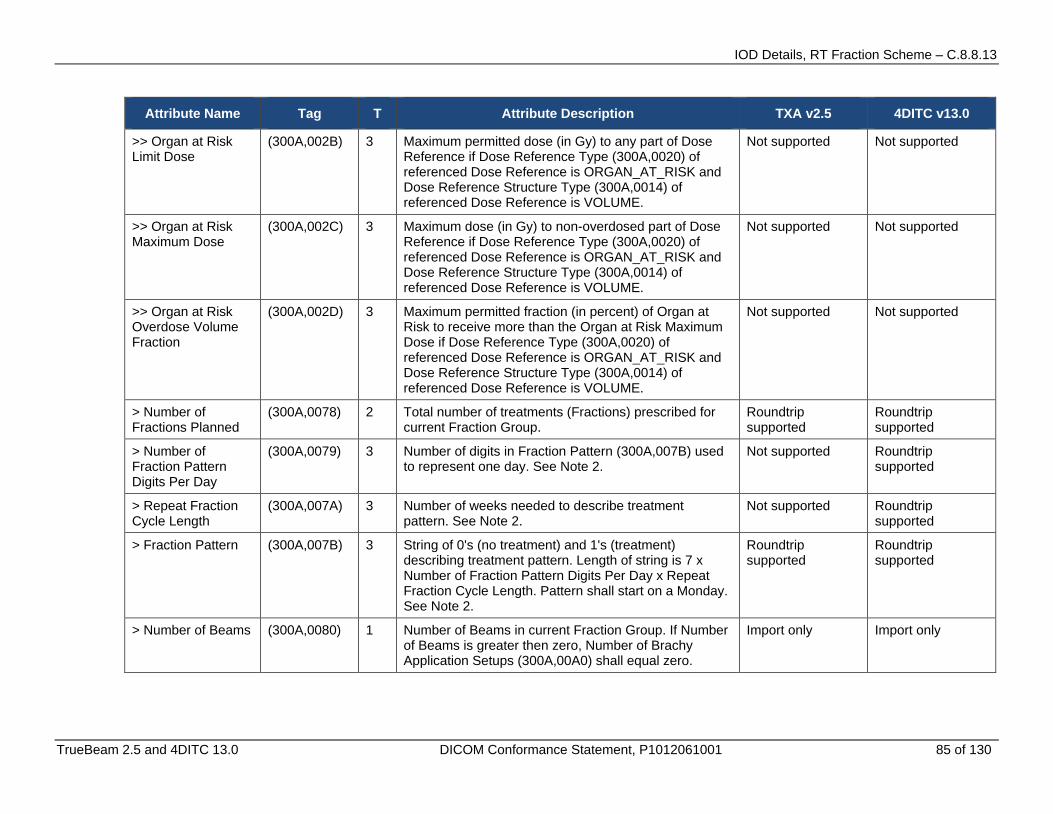
IOD Details, RT Fraction Scheme – C.8.8.13
TrueBeam 2.5 and 4DITC 13.0 DICOM Conformance Statement, P1012061001 85 of 130
Attribute Name Tag T Attribute Description TXA v2.5 4DITC v13.0
>> Organ at Risk Limit Dose
(300A,002B) 3 Maximum permitted dose (in Gy) to any part of Dose Reference if Dose Reference Type (300A,0020) of referenced Dose Reference is ORGAN_AT_RISK and Dose Reference Structure Type (300A,0014) of referenced Dose Reference is VOLUME.
Not supported Not supported
>> Organ at Risk Maximum Dose
(300A,002C) 3 Maximum dose (in Gy) to non-overdosed part of Dose Reference if Dose Reference Type (300A,0020) of referenced Dose Reference is ORGAN_AT_RISK and Dose Reference Structure Type (300A,0014) of referenced Dose Reference is VOLUME.
Not supported Not supported
>> Organ at Risk Overdose Volume Fraction
(300A,002D) 3 Maximum permitted fraction (in percent) of Organ at Risk to receive more than the Organ at Risk Maximum Dose if Dose Reference Type (300A,0020) of referenced Dose Reference is ORGAN_AT_RISK and Dose Reference Structure Type (300A,0014) of referenced Dose Reference is VOLUME.
Not supported Not supported
> Number of Fractions Planned
(300A,0078) 2 Total number of treatments (Fractions) prescribed for current Fraction Group.
Roundtrip supported
Roundtrip supported
> Number of Fraction Pattern Digits Per Day
(300A,0079) 3 Number of digits in Fraction Pattern (300A,007B) used to represent one day. See Note 2.
Not supported Roundtrip supported
> Repeat Fraction Cycle Length
(300A,007A) 3 Number of weeks needed to describe treatment pattern. See Note 2.
Not supported Roundtrip supported
> Fraction Pattern (300A,007B) 3 String of 0's (no treatment) and 1's (treatment) describing treatment pattern. Length of string is 7 x Number of Fraction Pattern Digits Per Day x Repeat Fraction Cycle Length. Pattern shall start on a Monday. See Note 2.
Roundtrip supported
Roundtrip supported
> Number of Beams (300A,0080) 1 Number of Beams in current Fraction Group. If Number of Beams is greater then zero, Number of Brachy Application Setups (300A,00A0) shall equal zero.
Import only Import only
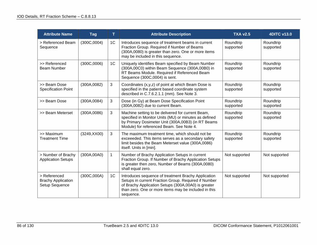
IOD Details, RT Fraction Scheme – C.8.8.13
86 of 130 TrueBeam 2.5 and 4DITC 13.0 DICOM Conformance Statement, P1012061001
Attribute Name Tag T Attribute Description TXA v2.5 4DITC v13.0
> Referenced Beam Sequence
(300C,0004) 1C Introduces sequence of treatment beams in current Fraction Group. Required if Number of Beams (300A,0080) is greater than zero. One or more items may be included in this sequence.
Roundtrip supported
Roundtrip supported
>> Referenced Beam Number
(300C,0006) 1C Uniquely identifies Beam specified by Beam Number (300A,00C0) within Beam Sequence (300A,00B0) in RT Beams Module. Required if Referenced Beam Sequence (300C,0004) is sent.
Roundtrip supported
Roundtrip supported
>> Beam Dose Specification Point
(300A,0082) 3 Coordinates (x,y,z) of point at which Beam Dose is specified in the patient based coordinate system described in C.7.6.2.1.1 (mm). See Note 3.
Roundtrip supported
Roundtrip supported
>> Beam Dose (300A,0084) 3 Dose (in Gy) at Beam Dose Specification Point (300A,0082) due to current Beam.
Roundtrip supported
Roundtrip supported
>> Beam Meterset (300A,0086) 3 Machine setting to be delivered for current Beam, specified in Monitor Units (MU) or minutes as defined by Primary Dosimeter Unit (300A,00B3) (in RT Beams Module) for referenced Beam. See Note 4.
Roundtrip supported
Roundtrip supported
>> Maximum Treatment Time
(3249,XX00) 3 The maximum treatment time, which should not be exceeeded. This items serves as a secondary safety limit besides the Beam Meterset value (300A,0086) itself. Units in [min].
Roundtrip supported
Roundtrip supported
> Number of Brachy Application Setups
(300A,00A0) 1 Number of Brachy Application Setups in current Fraction Group. If Number of Brachy Application Setups is greater then zero, Number of Beams (300A,0080) shall equal zero.
Not supported Not supported
> Referenced Brachy Application Setup Sequence
(300C,000A) 1C Introduces sequence of treatment Brachy Application Setups in current Fraction Group. Required if Number of Brachy Application Setups (300A,00A0) is greater than zero. One or more items may be included in this sequence.
Not supported Not supported

IOD Details, RT Beams – C.8.8.14
TrueBeam 2.5 and 4DITC 13.0 DICOM Conformance Statement, P1012061001 87 of 130
Attribute Name Tag T Attribute Description TXA v2.5 4DITC v13.0
>> Referenced Brachy Application Setup Number
(300C,000C) 1C Uniquely identifies Brachy Application Setup specified by Brachy Application Setup Number (300A,0234) within Brachy Application Setup Sequence (300A,0230) in RT Brachy Application Setups Module. Required if Referenced Brachy Application Setup Sequence (300C,000A) is sent.
Not supported Not supported
>> Brachy Application Setup Dose Specification Point
(300A,00A2) 3 Coordinates (x,y,z) of point in the patient based coordinate system described in C.7.6.2.1.1 at which Brachy Application Setup Dose (300A,00A4) is specified (mm).
Not supported Not supported
>> Brachy Application Setup Dose
(300A,00A4) 3 Dose (in Gy) at Brachy Application Setup Dose Specification Point (300A,00A2) due to current Brachy Application Setup.
Not supported Not supported
> Prescribed Dose per Fraction
(3269,XX00) 3 Not supported Not supported
> Prescribed Percentage
(3269,XX01) 3 Not supported Not supported
> Plan Normalization Factor
(3269,XX02) 3 Not supported Not supported
Table C-14: RT Fraction Scheme – C.8.8.13
C.2.10 RT Beams – C.8.8.14
Attribute Name Tag T Attribute Description TXA v2.5 4DITC v13.0
Beam Sequence (300A,00B0) 1 Introduces sequence of treatment beams for current RT Plan. One or more items may be included in this sequence.
Roundtrip supported
Roundtrip supported
> Beam Number (300A,00C0) 1 Identification number of the Beam. The value of Beam Number (300A,00C0) shall be unique within the RT Plan in which it is created. See Note 1.
Roundtrip supported
Roundtrip supported
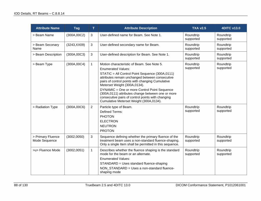
IOD Details, RT Beams – C.8.8.14
88 of 130 TrueBeam 2.5 and 4DITC 13.0 DICOM Conformance Statement, P1012061001
Attribute Name Tag T Attribute Description TXA v2.5 4DITC v13.0
> Beam Name (300A,00C2) 3 User-defined name for Beam. See Note 1. Roundtrip supported
Roundtrip supported
> Beam Seconary Name
(3243,XX09) 3 User-defined secondary name for Beam. Roundtrip supported
Roundtrip supported
> Beam Description (300A,00C3) 3 User-defined description for Beam. See Note 1. Roundtrip supported
Roundtrip supported
> Beam Type (300A,00C4) 1 Motion characteristic of Beam. See Note 5. Enumerated Values: STATIC = All Control Point Sequence (300A,0111) attributes remain unchanged between consecutive pairs of control points with changing Cumulative Meterset Weight (300A,0134). DYNAMIC = One or more Control Point Sequence (300A,0111) attributes change between one or more consecutive pairs of control points with changing Cumulative Meterset Weight (300A,0134).
Roundtrip supported
Roundtrip supported
> Radiation Type (300A,00C6) 2 Particle type of Beam. Defined Terms: PHOTON ELECTRON NEUTRON PROTON
Roundtrip supported
Roundtrip supported
> Primary Fluence Mode Sequence
(3002,0050) 3 Sequence defining whether the primary fluence of the treatment beam uses a non-standard fluence-shaping. Only a single Item shall be permitted in this sequence.
Roundtrip supported
Roundtrip supported
>u> Fluence Mode (3002,0051) 1 Describes whether the fluence shaping is the standard mode for the beam or an alternate. Enumerated Values: STANDARD = Uses standard fluence-shaping NON_STANDARD = Uses a non-standard fluence-shaping mode
Roundtrip supported
Roundtrip supported
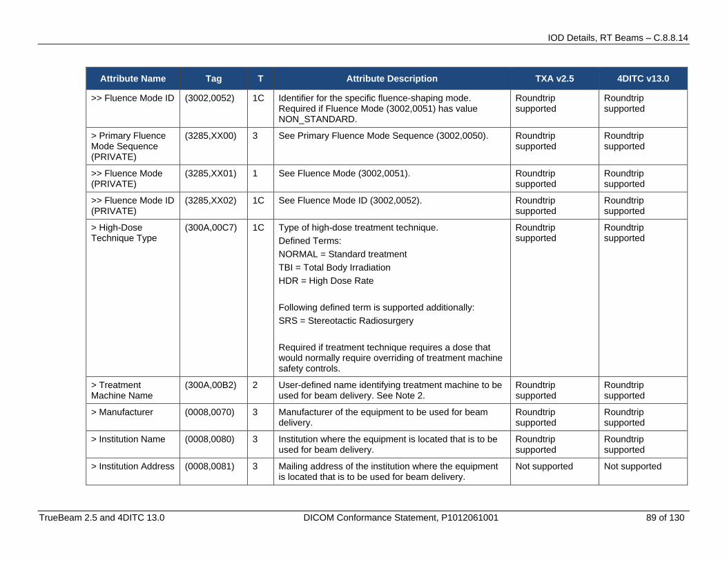
IOD Details, RT Beams – C.8.8.14
TrueBeam 2.5 and 4DITC 13.0 DICOM Conformance Statement, P1012061001 89 of 130
Attribute Name Tag T Attribute Description TXA v2.5 4DITC v13.0
>> Fluence Mode ID (3002,0052) 1C Identifier for the specific fluence-shaping mode. Required if Fluence Mode (3002,0051) has value NON_STANDARD.
Roundtrip supported
Roundtrip supported
> Primary Fluence Mode Sequence (PRIVATE)
(3285,XX00) 3 See Primary Fluence Mode Sequence (3002,0050). Roundtrip supported
Roundtrip supported
>> Fluence Mode (PRIVATE)
(3285,XX01) 1 See Fluence Mode (3002,0051). Roundtrip supported
Roundtrip supported
>> Fluence Mode ID (PRIVATE)
(3285,XX02) 1C See Fluence Mode ID (3002,0052). Roundtrip supported
Roundtrip supported
> High-Dose Technique Type
(300A,00C7) 1C Type of high-dose treatment technique. Defined Terms: NORMAL = Standard treatment TBI = Total Body Irradiation HDR = High Dose Rate Following defined term is supported additionally: SRS = Stereotactic Radiosurgery Required if treatment technique requires a dose that would normally require overriding of treatment machine safety controls.
Roundtrip supported
Roundtrip supported
> Treatment Machine Name
(300A,00B2) 2 User-defined name identifying treatment machine to be used for beam delivery. See Note 2.
Roundtrip supported
Roundtrip supported
> Manufacturer (0008,0070) 3 Manufacturer of the equipment to be used for beam delivery.
Roundtrip supported
Roundtrip supported
> Institution Name (0008,0080) 3 Institution where the equipment is located that is to be used for beam delivery.
Roundtrip supported
Roundtrip supported
> Institution Address (0008,0081) 3 Mailing address of the institution where the equipment is located that is to be used for beam delivery.
Not supported Not supported
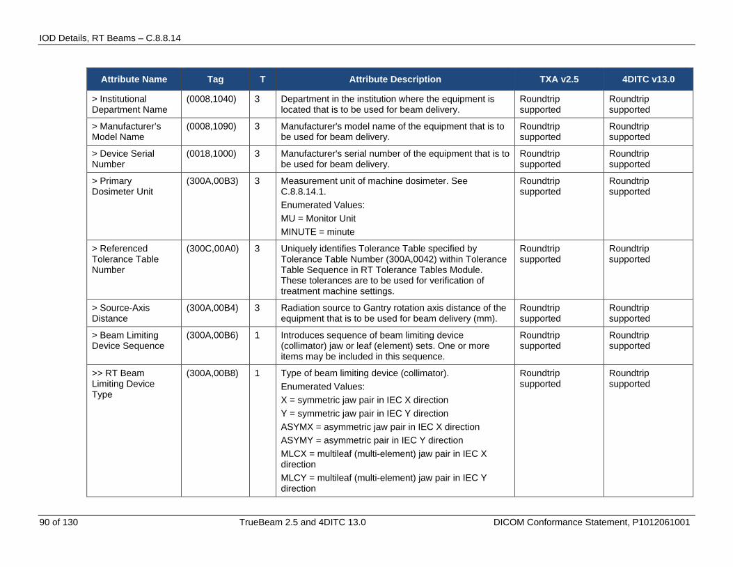
IOD Details, RT Beams – C.8.8.14
90 of 130 TrueBeam 2.5 and 4DITC 13.0 DICOM Conformance Statement, P1012061001
Attribute Name Tag T Attribute Description TXA v2.5 4DITC v13.0
> Institutional Department Name
(0008,1040) 3 Department in the institution where the equipment is located that is to be used for beam delivery.
Roundtrip supported
Roundtrip supported
> Manufacturer’s Model Name
(0008,1090) 3 Manufacturer's model name of the equipment that is to be used for beam delivery.
Roundtrip supported
Roundtrip supported
> Device Serial Number
(0018,1000) 3 Manufacturer's serial number of the equipment that is to be used for beam delivery.
Roundtrip supported
Roundtrip supported
> Primary Dosimeter Unit
(300A,00B3) 3 Measurement unit of machine dosimeter. See C.8.8.14.1. Enumerated Values: MU = Monitor Unit MINUTE = minute
Roundtrip supported
Roundtrip supported
> Referenced Tolerance Table Number
(300C,00A0) 3 Uniquely identifies Tolerance Table specified by Tolerance Table Number (300A,0042) within Tolerance Table Sequence in RT Tolerance Tables Module. These tolerances are to be used for verification of treatment machine settings.
Roundtrip supported
Roundtrip supported
> Source-Axis Distance
(300A,00B4) 3 Radiation source to Gantry rotation axis distance of the equipment that is to be used for beam delivery (mm).
Roundtrip supported
Roundtrip supported
> Beam Limiting Device Sequence
(300A,00B6) 1 Introduces sequence of beam limiting device (collimator) jaw or leaf (element) sets. One or more items may be included in this sequence.
Roundtrip supported
Roundtrip supported
>> RT Beam Limiting Device Type
(300A,00B8) 1 Type of beam limiting device (collimator). Enumerated Values: X = symmetric jaw pair in IEC X direction Y = symmetric jaw pair in IEC Y direction ASYMX = asymmetric jaw pair in IEC X direction ASYMY = asymmetric pair in IEC Y direction MLCX = multileaf (multi-element) jaw pair in IEC X direction MLCY = multileaf (multi-element) jaw pair in IEC Y direction
Roundtrip supported
Roundtrip supported

IOD Details, RT Beams – C.8.8.14
TrueBeam 2.5 and 4DITC 13.0 DICOM Conformance Statement, P1012061001 91 of 130
Attribute Name Tag T Attribute Description TXA v2.5 4DITC v13.0
>> Source to Beam Limiting Device Distance
(300A,00BA) 3 Radiation source to beam limiting device (collimator) distance of the equipment that is to be used for beam delivery (mm).
Roundtrip supported
Roundtrip supported
>> Number of Leaf/Jaw Pairs
(300A,00BC) 1 Number of leaf (element) or jaw pairs (equal to 1 for standard beam limiting device jaws).
Roundtrip supported
Roundtrip supported
>> Leaf Position Boundaries
(300A,00BE) 2C Boundaries of beam limiting device (collimator) leaves (in mm) in IEC BEAM LIMITING DEVICE coordinate axis appropriate to RT Beam Limiting Device Type (300A,00B8), i.e. X-axis for MLCY, Y- axis for MLCX. Contains N+1 values, where N is the Number of Leaf/Jaw Pairs (300A,00BC), starting from Leaf (Element) Pair 1. Required if Beam Limiting Device Sequence (300A,00B6) is sent and RT Beam Limiting Device Type (300A,00B8) is MLCX or MLCY. See Note 3.
Roundtrip supported
Roundtrip supported
> Referenced Patient Setup Number
(300C,006A) 3 Uniquely identifies Patient Setup to be used for current beam, specified by Patient Setup Number (300A,0182) within Patient Setup Sequence of RT Patient Setup Module.
Roundtrip supported
Roundtrip supported
> Referenced Reference Image Sequence
(300C,0042) 3 Introduces sequence of reference images used for validation of current beam. One or more items may be included in this sequence.
Roundtrip supported
Roundtrip supported
>> Referenced SOP Class UID
(0008,1150) 1C Uniquely identifies the referenced SOP Class. Required if Referenced Reference Image Sequence (300C,0042) is sent.
Roundtrip supported
Roundtrip supported
>> Referenced SOP Instance UID
(0008,1155) 1C Uniquely identifies the referenced SOP Instance. Required if Referenced Reference Image Sequence (300C,0042) is sent.
Roundtrip supported
Roundtrip supported
>> Reference Image Number
(300A,00C8) 1C Uniquely identifies Reference Image within Referenced Reference Image Sequence (300A,0042). Required if Referenced Reference Image Sequence (300A,0042) is sent.
Roundtrip supported
Roundtrip supported
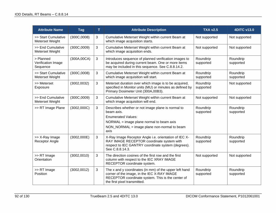
IOD Details, RT Beams – C.8.8.14
92 of 130 TrueBeam 2.5 and 4DITC 13.0 DICOM Conformance Statement, P1012061001
Attribute Name Tag T Attribute Description TXA v2.5 4DITC v13.0
>> Start Cumulative Meterset Weight
(300C,0008) 3 Cumulative Meterset Weight within current Beam at which image acquisition starts.
Not supported Not supported
>> End Cumulative Meterset Weight
(300C,0009) 3 Cumulative Meterset Weight within current Beam at which image acquisition ends.
Not supported Not supported
> Planned Verification Image Sequence
(300A,00CA) 3 Introduces sequence of planned verification images to be acquired during current beam. One or more items may be included in this sequence. See C.8.8.14.2.
Roundtrip supported
Roundtrip supported
>> Start Cumulative Meterset Weight
(300C,0008) 3 Cumulative Meterset Weight within current Beam at which image acquisition will start.
Roundtrip supported
Roundtrip supported
>> Meterset Exposure
(3002,0032) 3 Meterset duration over which image is to be acquired, specified in Monitor units (MU) or minutes as defined by Primary Dosimeter Unit (300A,00B3).
Roundtrip supported
Not supported
>> End Cumulative Meterset Weight
(300C,0009) 3 Cumulative Meterset Weight within current Beam at which image acquisition will end.
Not supported Not supported
>> RT Image Plane (3002,000C) 3 Describes whether or not image plane is normal to beam axis. Enumerated Values: NORMAL = image plane normal to beam axis NON_NORMAL = image plane non-normal to beam axis
Roundtrip supported
Roundtrip supported
>> X-Ray Image Receptor Angle
(3002,000E) 3 X-Ray Image Receptor Angle i.e. orientation of IEC X-RAY IMAGE RECEPTOR coordinate system with respect to IEC GANTRY coordinate system (degrees). See C.8.8.14.3.
Roundtrip supported
Roundtrip supported
>> RT Image Orientation
(3002,0010) 3 The direction cosines of the first row and the first column with respect to the IEC XRAY IMAGE RECEPTOR coordinate system.
Not supported Not supported
>> RT Image Position
(3002,0012) 3 The x and y coordinates (in mm) of the upper left hand corner of the image, in the IEC X-RAY IMAGE RECEPTOR coordinate system. This is the center of the first pixel transmitted.
Roundtrip supported
Roundtrip supported
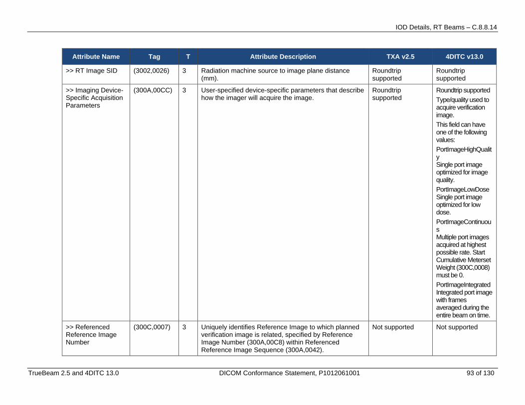
IOD Details, RT Beams – C.8.8.14
TrueBeam 2.5 and 4DITC 13.0 DICOM Conformance Statement, P1012061001 93 of 130
Attribute Name Tag T Attribute Description TXA v2.5 4DITC v13.0
>> RT Image SID (3002,0026) 3 Radiation machine source to image plane distance (mm).
Roundtrip supported
Roundtrip supported
>> Imaging Device-Specific Acquisition Parameters
(300A,00CC) 3 User-specified device-specific parameters that describe how the imager will acquire the image.
Roundtrip supported
Roundtrip supported Type/quality used to acquire verification image. This field can have one of the following values: PortImageHighQuality Single port image optimized for image quality. PortImageLowDose Single port image optimized for low dose. PortImageContinuous Multiple port images acquired at highest possible rate. Start Cumulative Meterset Weight (300C,0008) must be 0. PortImageIntegrated Integrated port image with frames averaged during the entire beam on time.
>> Referenced Reference Image Number
(300C,0007) 3 Uniquely identifies Reference Image to which planned verification image is related, specified by Reference Image Number (300A,00C8) within Referenced Reference Image Sequence (300A,0042).
Not supported Not supported
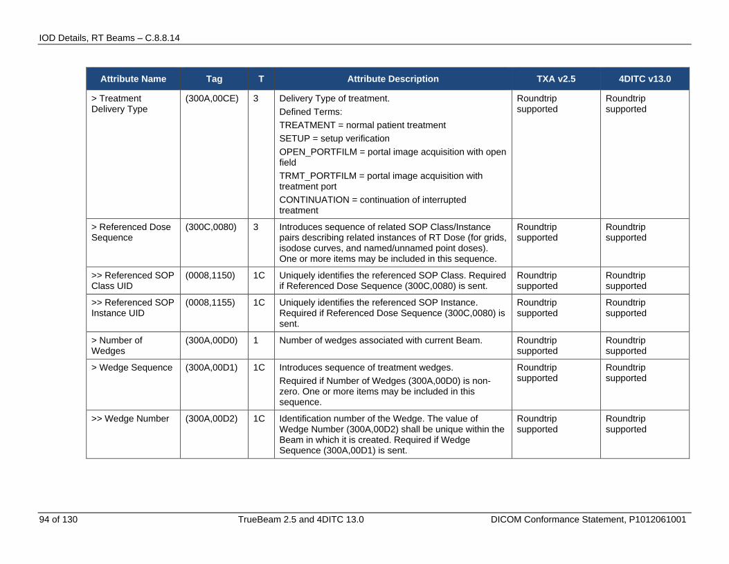
IOD Details, RT Beams – C.8.8.14
94 of 130 TrueBeam 2.5 and 4DITC 13.0 DICOM Conformance Statement, P1012061001
Attribute Name Tag T Attribute Description TXA v2.5 4DITC v13.0
> Treatment Delivery Type
(300A,00CE) 3 Delivery Type of treatment. Defined Terms: TREATMENT = normal patient treatment SETUP = setup verification OPEN_PORTFILM = portal image acquisition with open field TRMT_PORTFILM = portal image acquisition with treatment port CONTINUATION = continuation of interrupted treatment
Roundtrip supported
Roundtrip supported
> Referenced Dose Sequence
(300C,0080) 3 Introduces sequence of related SOP Class/Instance pairs describing related instances of RT Dose (for grids, isodose curves, and named/unnamed point doses). One or more items may be included in this sequence.
Roundtrip supported
Roundtrip supported
>> Referenced SOP Class UID
(0008,1150) 1C Uniquely identifies the referenced SOP Class. Required if Referenced Dose Sequence (300C,0080) is sent.
Roundtrip supported
Roundtrip supported
>> Referenced SOP Instance UID
(0008,1155) 1C Uniquely identifies the referenced SOP Instance. Required if Referenced Dose Sequence (300C,0080) is sent.
Roundtrip supported
Roundtrip supported
> Number of Wedges
(300A,00D0) 1 Number of wedges associated with current Beam. Roundtrip supported
Roundtrip supported
> Wedge Sequence (300A,00D1) 1C Introduces sequence of treatment wedges. Required if Number of Wedges (300A,00D0) is non-zero. One or more items may be included in this sequence.
Roundtrip supported
Roundtrip supported
>> Wedge Number (300A,00D2) 1C Identification number of the Wedge. The value of Wedge Number (300A,00D2) shall be unique within the Beam in which it is created. Required if Wedge Sequence (300A,00D1) is sent.
Roundtrip supported
Roundtrip supported
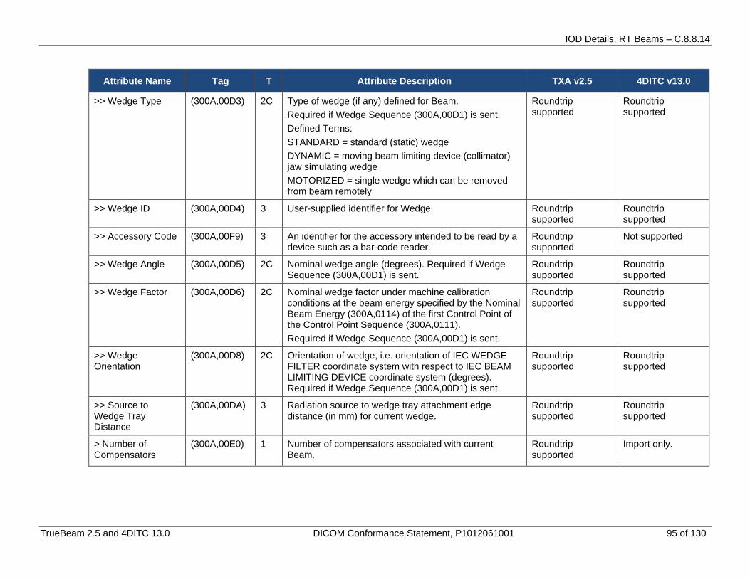
IOD Details, RT Beams – C.8.8.14
TrueBeam 2.5 and 4DITC 13.0 DICOM Conformance Statement, P1012061001 95 of 130
Attribute Name Tag T Attribute Description TXA v2.5 4DITC v13.0
>> Wedge Type (300A,00D3) 2C Type of wedge (if any) defined for Beam. Required if Wedge Sequence (300A,00D1) is sent. Defined Terms: STANDARD = standard (static) wedge DYNAMIC = moving beam limiting device (collimator) jaw simulating wedge MOTORIZED = single wedge which can be removed from beam remotely
Roundtrip supported
Roundtrip supported
>> Wedge ID (300A,00D4) 3 User-supplied identifier for Wedge. Roundtrip supported
Roundtrip supported
>> Accessory Code (300A,00F9) 3 An identifier for the accessory intended to be read by a device such as a bar-code reader.
Roundtrip supported
Not supported
>> Wedge Angle (300A,00D5) 2C Nominal wedge angle (degrees). Required if Wedge Sequence (300A,00D1) is sent.
Roundtrip supported
Roundtrip supported
>> Wedge Factor (300A,00D6) 2C Nominal wedge factor under machine calibration conditions at the beam energy specified by the Nominal Beam Energy (300A,0114) of the first Control Point of the Control Point Sequence (300A,0111). Required if Wedge Sequence (300A,00D1) is sent.
Roundtrip supported
Roundtrip supported
>> Wedge Orientation
(300A,00D8) 2C Orientation of wedge, i.e. orientation of IEC WEDGE FILTER coordinate system with respect to IEC BEAM LIMITING DEVICE coordinate system (degrees). Required if Wedge Sequence (300A,00D1) is sent.
Roundtrip supported
Roundtrip supported
>> Source to Wedge Tray Distance
(300A,00DA) 3 Radiation source to wedge tray attachment edge distance (in mm) for current wedge.
Roundtrip supported
Roundtrip supported
> Number of Compensators
(300A,00E0) 1 Number of compensators associated with current Beam.
Roundtrip supported
Import only.

IOD Details, RT Beams – C.8.8.14
96 of 130 TrueBeam 2.5 and 4DITC 13.0 DICOM Conformance Statement, P1012061001
Attribute Name Tag T Attribute Description TXA v2.5 4DITC v13.0
> Total Compensator Tray Factor
(300A,00E2) 3 Compensator Tray transmission factor (between 0 and 1), at the beam energy specified by the Nominal Beam Energy (300A,0114) of the first Control Point of the Control Point Sequence (300A,0111).
Not supported Roundtrip supported
> Compensator Sequence
(300A,00E3) 1C Introduces sequence of treatment compensators. Required if Number of Compensators (300A,00E0) is non-zero. One or more items may be included in this sequence.
Roundtrip supported
Roundtrip supported
>> Compensator Description
(300A,02EB) 3 User defined description for the compensator Not supported Not supported
>> Compensator Type
(300A,00EE) 3 Type of compensator (if any). Defined Terms: STANDARD = physical (static) compensator DYNAMIC = moving Beam Limiting Device (collimator) simulating physical compensator
Roundtrip supported
Roundtrip supported
>> Material ID (300A,00E1) 2C User-supplied identifier for material used to manufacture Compensator. Required if Number of Compensators (300A,00E0) is non-zero.
Roundtrip supported
Roundtrip supported
>> Compensator ID (300A,00E5) 3 User-supplied identifier for compensator. Roundtrip supported
Roundtrip supported
>> Accessory Code (300A,00F9) 3 An identifier for the accessory intended to be read by a device such as a bar-code reader.
Roundtrip supported
Roundtrip supported
>> Source to Compensator Tray Distance
(300A,00E6) 2C Radiation source to compensator tray attachment edge distance (in mm) for current compensator. Required if Compensator Sequence (300A,00E3) is sent.
Roundtrip supported
Roundtrip supported
>> Compensator Divergence
(300A,02E0) 3 Indicates presence or absence of geometrical divergence of the compensator. Enumerated Values: PRESENT = the compensator is shaped according to the beam geometrical divergence. ABSENT = the compensator is not shaped according to the beam geometrical divergence.
Not supported Roundtrip supported
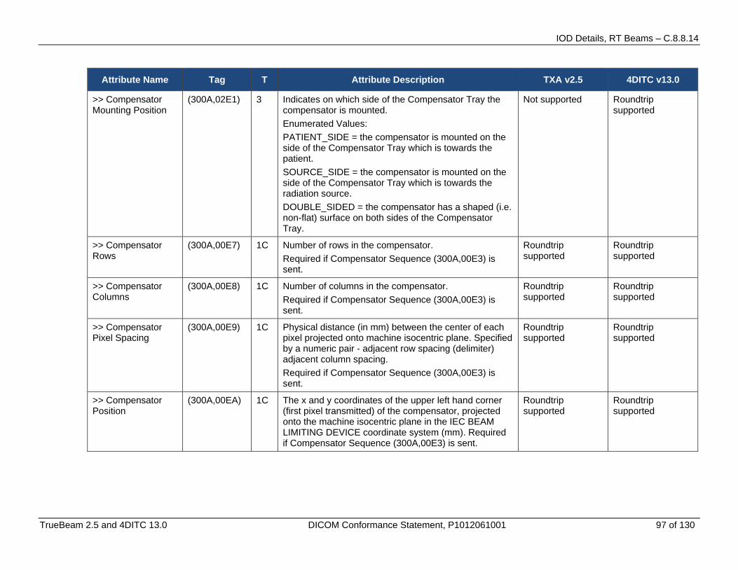
IOD Details, RT Beams – C.8.8.14
TrueBeam 2.5 and 4DITC 13.0 DICOM Conformance Statement, P1012061001 97 of 130
Attribute Name Tag T Attribute Description TXA v2.5 4DITC v13.0
>> Compensator Mounting Position
(300A,02E1) 3 Indicates on which side of the Compensator Tray the compensator is mounted. Enumerated Values: PATIENT_SIDE = the compensator is mounted on the side of the Compensator Tray which is towards the patient. SOURCE_SIDE = the compensator is mounted on the side of the Compensator Tray which is towards the radiation source. DOUBLE_SIDED = the compensator has a shaped (i.e. non-flat) surface on both sides of the Compensator Tray.
Not supported Roundtrip supported
>> Compensator Rows
(300A,00E7) 1C Number of rows in the compensator. Required if Compensator Sequence (300A,00E3) is sent.
Roundtrip supported
Roundtrip supported
>> Compensator Columns
(300A,00E8) 1C Number of columns in the compensator. Required if Compensator Sequence (300A,00E3) is sent.
Roundtrip supported
Roundtrip supported
>> Compensator Pixel Spacing
(300A,00E9) 1C Physical distance (in mm) between the center of each pixel projected onto machine isocentric plane. Specified by a numeric pair - adjacent row spacing (delimiter) adjacent column spacing. Required if Compensator Sequence (300A,00E3) is sent.
Roundtrip supported
Roundtrip supported
>> Compensator Position
(300A,00EA) 1C The x and y coordinates of the upper left hand corner (first pixel transmitted) of the compensator, projected onto the machine isocentric plane in the IEC BEAM LIMITING DEVICE coordinate system (mm). Required if Compensator Sequence (300A,00E3) is sent.
Roundtrip supported
Roundtrip supported

IOD Details, RT Beams – C.8.8.14
98 of 130 TrueBeam 2.5 and 4DITC 13.0 DICOM Conformance Statement, P1012061001
Attribute Name Tag T Attribute Description TXA v2.5 4DITC v13.0
>> Compensator Transmission Data
(300A,00EB) 1C A data stream of the pixel samples which comprise the compensator, expressed as broad-beam transmission values (between 0 and 1) along a ray line passing through the pixel, at the beam energy specified by the Nominal Beam Energy (300A,0114) of the first Control Point of the Control Point Sequence (300A,0111). The order of pixels sent is left to right, top to bottom, i.e., the upper left pixel is sent first followed by the remainder of the first row , followed by the first pixel of the 2nd row, then the remainder of the 2nd row and so on) when viewed from the radiation source. Required if Compensator Sequence (300A,00E3) is sent and Material ID (300A,00E1) is zero- length. See C.8.8.14.10. Note: Compensator Transmission Data may not be properly encoded if Explicit-VR transfer syntax is used and the VL of this attribute exceeds 65534 bytes.
Roundtrip supported
Roundtrip supported
>> Compensator Thickness Data
(300A,00EC) 1C A data stream of the pixel samples which comprise the compensator, expressed as thicknesses (in mm). The order of pixels sent is left to right, top to bottom, i.e., the upper left pixel is sent first followed by the remainder of the first row , followed by the first pixel of the 2nd row, then the remainder of the 2nd row and so on) when viewed from the radiation source. Required if Compensator Sequence (300A,00E3) is sent and Material ID (300A,00E1) is nonzero length. See C.8.8.14.9 and C.8.8.14.10. Note: Compensator Thickness Data may not be properly encoded if Explicit- VR transfer syntax is used and the VL of this attribute exceeds 65534 bytes.
Roundtrip supported
Roundtrip supported
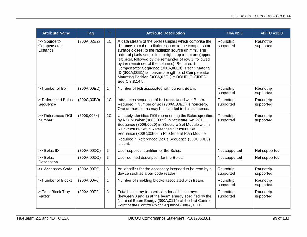
IOD Details, RT Beams – C.8.8.14
TrueBeam 2.5 and 4DITC 13.0 DICOM Conformance Statement, P1012061001 99 of 130
Attribute Name Tag T Attribute Description TXA v2.5 4DITC v13.0
>> Source to Compensator Distance
(300A,02E2) 1C A data stream of the pixel samples which comprise the distance from the radiation source to the compensator surface closest to the radiation source (in mm). The order of pixels sent is left to right, top to bottom (upper left pixel, followed by the remainder of row 1, followed by the remainder of the columns). Required if Compensator Sequence (300A,00E3) is sent, Material ID (300A,00E1) is non-zero length, and Compensator Mounting Position (300A,02E1) is DOUBLE_SIDED. See C.8.8.14.9.
Roundtrip supported
Roundtrip supported
> Number of Boli (300A,00ED) 1 Number of boli associated with current Beam. Roundtrip supported
Roundtrip supported
> Referenced Bolus Sequence
(300C,00B0) 1C Introduces sequence of boli associated with Beam. Required if Number of Boli (300A,00ED) is non-zero. One or more items may be included in this sequence.
Roundtrip supported
Roundtrip supported
>> Referenced ROI Number
(3006,0084) 1C Uniquely identifies ROI representing the Bolus specified by ROI Number (3006,0022) in Structure Set ROI Sequence (3006,0020) in Structure Set Module within RT Structure Set in Referenced Structure Set Sequence (300C,0060) in RT General Plan Module. Required if Referenced Bolus Sequence (300C,00B0) is sent.
Roundtrip supported
Roundtrip supported
>> Bolus ID (300A,00DC) 3 User-supplied identifier for the Bolus. Not supported Not supported
>> Bolus Description
(300A,00DD) 3 User-defined description for the Bolus. Not supported Not supported
>> Accessory Code (300A,00F9) 3 An identifier for the accessory intended to be read by a device such as a bar-code reader.
Roundtrip supported
Roundtrip supported
> Number of Blocks (300A,00F0) 1 Number of shielding blocks associated with Beam. Roundtrip supported
Roundtrip supported
> Total Block Tray Factor
(300A,00F2) 3 Total block tray transmission for all block trays (between 0 and 1) at the beam energy specified by the Nominal Beam Energy (300A,0114) of the first Control Point of the Control Point Sequence (300A,0111).
Roundtrip supported
Roundtrip supported

IOD Details, RT Beams – C.8.8.14
100 of 130 TrueBeam 2.5 and 4DITC 13.0 DICOM Conformance Statement, P1012061001
Attribute Name Tag T Attribute Description TXA v2.5 4DITC v13.0
> Block Sequence (300A,00F4) 1C Introduces sequence of blocks associated with Beam. Required if Number of Blocks (300A,00F0) is non-zero. One or more items may be included in this sequence.
Roundtrip supported
Roundtrip supported
>> Block Tray ID (300A,00F5) 3 User-supplied identifier for block tray. Roundtrip supported
Roundtrip supported
>> Accessory Code (300A,00F9) 3 An identifier for the accessory intended to be read by a device such as a bar-code reader.
Roundtrip supported
Roundtrip supported
>> Source to Block Tray Distance
(300A,00F6) 2C Radiation Source to attachment edge of block tray assembly (mm). Required if Block Sequence (300A,00F4) is sent.
Roundtrip supported
Roundtrip supported
>> Block Type (300A,00F8) 1C Type of block. Required if Block Sequence (300A,00F4) is sent. See C.8.8.14.4. Enumerated Values: SHIELDING = blocking material is inside contour APERTURE = blocking material is outside contour
Roundtrip supported
Roundtrip supported
>> Block Divergence
(300A,00FA) 2C Indicates presence or otherwise of geometrical divergence. Required if Block Sequence (300A,00F4) is sent. Enumerated Values: PRESENT = block edges are shaped for beam divergence ABSENT = block edges are not shaped for beam divergence
Roundtrip supported
Roundtrip supported
>> Block Mounting Position
(300A,00FB) 3 Indicates on which side of the Block Tray the block is mounted. Enumerated Values: PATIENT_SIDE = the block is mounted on the side of the Block Tray which is towards the patient. SOURCE_SIDE = the block is mounted on the side of the Block Tray which is towards the radiation source.
Not supported Not supported

IOD Details, RT Beams – C.8.8.14
TrueBeam 2.5 and 4DITC 13.0 DICOM Conformance Statement, P1012061001 101 of 130
Attribute Name Tag T Attribute Description TXA v2.5 4DITC v13.0
>> Block Number (300A,00FC) 1C Identification number of the Block. The value of Block Number (300A,00FC) shall be unique within the Beam in which it is created. Required if Block Sequence (300A,00F4) is sent.
Roundtrip supported
Roundtrip supported
>> Block Name (300A,00FE) 3 User-defined name for block. Roundtrip supported
Roundtrip supported
>> Material ID (300A,00E1) 2C User-supplied identifier for material used to manufacture Block. Required if Block Sequence (300A,00F4) is sent.
Roundtrip supported
Roundtrip supported
>> Block Thickness (300A,0100) 2C Physical thickness of block (in mm) parallel to radiation beam axis. Required if Block Sequence (300A,00F4) is sent and Material ID (300A,00E1) is non-zero length. See C.8.8.14.4.
Roundtrip supported
Roundtrip supported
>> Block Transmission
(300A,0102) 2C Transmission through the block (between 0 and 1) at the beam energy specified by the Nominal Beam Energy (300A,0114) of the first Control Point of the Control Point Sequence (300A,0111). Required if Block Sequence (300A,00F4) is sent and Material ID (300A,00E1) is zero length. See C.8.8.14.4.
Roundtrip supported
Roundtrip supported
>> Block Number of Points
(300A,0104) 2C Number of (x,y) pairs defining the block edge. Required if Block Sequence (300A,00F4) is sent.
Roundtrip supported
Roundtrip supported
>> Block Data (300A,0106) 2C A data stream of (x,y) pairs which comprise the block edge. The number of pairs shall be equal to Block Number of Points (300A,0104), and the vertices shall be interpreted as a closed polygon. Coordinates are projected onto the machine isocentric plane in the IEC BEAM LIMITING DEVICE coordinate system (mm). Required if Block Sequence (300A,00F4) is sent. See Note 4.
Roundtrip supported
Roundtrip supported
> Applicator Sequence
(300A,0107) 3 Introduces sequence of Applicators associated with Beam. Only a single item shall be permitted in this sequence.
Roundtrip supported
Roundtrip supported

IOD Details, RT Beams – C.8.8.14
102 of 130 TrueBeam 2.5 and 4DITC 13.0 DICOM Conformance Statement, P1012061001
Attribute Name Tag T Attribute Description TXA v2.5 4DITC v13.0
>> Applicator ID (300A,0108) 1C User or machine supplied identifier for Applicator. Required if Applicator Sequence (300A,0107) is sent.
Roundtrip supported
Roundtrip supported
>> Accessory Code (300A,00F9) 3 An identifier for the accessory intended to be read by a device such as a bar-code reader.
Roundtrip supported
Roundtrip supported
>> Applicator Type (300A,0109) 1C Type of Applicator. Required if Applicator Sequence (300A,0107) is sent. Defined Terms: ELECTRON_SQUARE = square electron applicator ELECTRON_RECT = rectangular electron applicator ELECTRON_CIRC = circular electron applicator ELECTRON_SHORT = short electron applicator ELECTRON_OPEN = open (dummy) electron applicator INTRAOPERATIVE = intraoperative (custom) applicator STEREOTACTIC = stereotactic applicator
Roundtrip supported
Roundtrip supported
>> Applicator Description
(300A,010A) 3 User-defined description for Applicator. Roundtrip supported
Roundtrip supported
> General Accessory Sequence
(300A,0420) 3 Introduces a Sequence of General Accessories associated with this Beam. One or more items may be included in this sequence.
Roundtrip supported
Roundtrip supported
>> General Accessory Number
(300A,0424) 1 Identification Number of the General Accessory. The value shall be unique within the sequence.
Roundtrip supported
Roundtrip supported
>> General Accessory ID
(300A,0421) 1 User or machine supplied identifier for General Accessory.
Roundtrip supported
Roundtrip supported
>> General Accessory Description
(300A,0422) 3 User supplied description of General Accessory. Roundtrip supported
Roundtrip supported

IOD Details, RT Beams – C.8.8.14
TrueBeam 2.5 and 4DITC 13.0 DICOM Conformance Statement, P1012061001 103 of 130
Attribute Name Tag T Attribute Description TXA v2.5 4DITC v13.0
>> General Accessory Type
(300A,0423) 3 Specifies the type of accessory. Defined Terms: GRATICULE = Accessory tray with a radio-opaque grid IMAGE_DETECTOR = Image acquisition device positioned in the beam line RETICLE = Accessory tray with radio-transparent markers or grid
Roundtrip supported
Roundtrip supported
>> Accessory Code (300A,00F9) 3 Machine-readable identifier for this accessory Roundtrip supported
Roundtrip supported
>> Source to General Accessory Distance
(3291,XX00) 3 Radiation source to accessory distance of the equipment that is to be used for beam delivery (mm).
Roundtrip supported
Roundtrip supported
> Final Cumulative Meterset Weight
(300A,010E) 1C Value of Cumulative Meterset Weight (300A,0134) for final Control Point in Control Point Sequence (300A,0111). Required if Cumulative Meterset Weight is non-null in Control Points specified within Control Point Sequence (300A,0111). See C.8.8.14.1.
Roundtrip supported
Roundtrip supported
> Number of Control Points
(300A,0110) 1 Number of control points in Beam. Roundtrip supported
Roundtrip supported
> Control Point Sequence
(300A,0111) 1 Introduces sequence of machine configurations describing treatment beam. Two or more items may be included in this sequence. See C.8.8.14.5 and C.8.8.14.6.
Roundtrip supported
Roundtrip supported
>> Control Point Index
(300A,0112) 1C Index of current Control Point, starting at 0 for first Control Point. Required if Control Point Sequence (300A,0111) is sent.
Roundtrip supported
Roundtrip supported
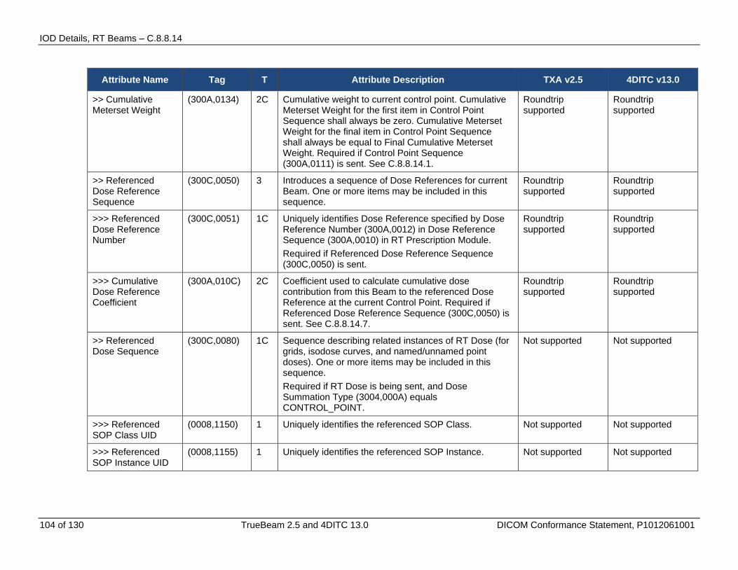
IOD Details, RT Beams – C.8.8.14
104 of 130 TrueBeam 2.5 and 4DITC 13.0 DICOM Conformance Statement, P1012061001
Attribute Name Tag T Attribute Description TXA v2.5 4DITC v13.0
>> Cumulative Meterset Weight
(300A,0134) 2C Cumulative weight to current control point. Cumulative Meterset Weight for the first item in Control Point Sequence shall always be zero. Cumulative Meterset Weight for the final item in Control Point Sequence shall always be equal to Final Cumulative Meterset Weight. Required if Control Point Sequence (300A,0111) is sent. See C.8.8.14.1.
Roundtrip supported
Roundtrip supported
>> Referenced Dose Reference Sequence
(300C,0050) 3 Introduces a sequence of Dose References for current Beam. One or more items may be included in this sequence.
Roundtrip supported
Roundtrip supported
>>> Referenced Dose Reference Number
(300C,0051) 1C Uniquely identifies Dose Reference specified by Dose Reference Number (300A,0012) in Dose Reference Sequence (300A,0010) in RT Prescription Module. Required if Referenced Dose Reference Sequence (300C,0050) is sent.
Roundtrip supported
Roundtrip supported
>>> Cumulative Dose Reference Coefficient
(300A,010C) 2C Coefficient used to calculate cumulative dose contribution from this Beam to the referenced Dose Reference at the current Control Point. Required if Referenced Dose Reference Sequence (300C,0050) is sent. See C.8.8.14.7.
Roundtrip supported
Roundtrip supported
>> Referenced Dose Sequence
(300C,0080) 1C Sequence describing related instances of RT Dose (for grids, isodose curves, and named/unnamed point doses). One or more items may be included in this sequence. Required if RT Dose is being sent, and Dose Summation Type (3004,000A) equals CONTROL_POINT.
Not supported Not supported
>>> Referenced SOP Class UID
(0008,1150) 1 Uniquely identifies the referenced SOP Class. Not supported Not supported
>>> Referenced SOP Instance UID
(0008,1155) 1 Uniquely identifies the referenced SOP Instance. Not supported Not supported
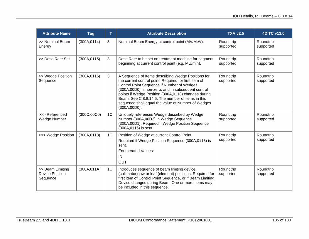
IOD Details, RT Beams – C.8.8.14
TrueBeam 2.5 and 4DITC 13.0 DICOM Conformance Statement, P1012061001 105 of 130
Attribute Name Tag T Attribute Description TXA v2.5 4DITC v13.0
>> Nominal Beam Energy
(300A,0114) 3 Nominal Beam Energy at control point (MV/MeV). Roundtrip supported
Roundtrip supported
>> Dose Rate Set (300A,0115) 3 Dose Rate to be set on treatment machine for segment beginning at current control point (e.g. MU/min).
Roundtrip supported
Roundtrip supported
>> Wedge Position Sequence
(300A,0116) 3 A Sequence of Items describing Wedge Positions for the current control point. Required for first item of Control Point Sequence if Number of Wedges (300A,00D0) is non-zero, and in subsequent control points if Wedge Position (300A,0118) changes during Beam. See C.8.8.14.5. The number of items in this sequence shall equal the value of Number of Wedges (300A,00D0).
Roundtrip supported
Roundtrip supported
>>> Referenced Wedge Number
(300C,00C0) 1C Uniquely references Wedge described by Wedge Number (300A,00D2) in Wedge Sequence (300A,00D1). Required if Wedge Position Sequence (300A,0116) is sent.
Roundtrip supported
Roundtrip supported
>>> Wedge Position (300A,0118) 1C Position of Wedge at current Control Point. Required if Wedge Position Sequence (300A,0116) is sent. Enumerated Values: IN OUT
Roundtrip supported
Roundtrip supported
>> Beam Limiting Device Position Sequence
(300A,011A) 1C Introduces sequence of beam limiting device (collimator) jaw or leaf (element) positions. Required for first item of Control Point Sequence, or if Beam Limiting Device changes during Beam. One or more items may be included in this sequence.
Roundtrip supported
Roundtrip supported

IOD Details, RT Beams – C.8.8.14
106 of 130 TrueBeam 2.5 and 4DITC 13.0 DICOM Conformance Statement, P1012061001
Attribute Name Tag T Attribute Description TXA v2.5 4DITC v13.0
>>> RT Beam Limiting Device Type
(300A,00B8) 1C Type of beam limiting device (collimator). The value of this attribute shall correspond to RT Beam Limiting Device Type (300A,00B8) defined in an item of Beam Limiting Device Sequence (300A,00B6). Required if Beam Limiting Device Position Sequence (300A,011A) is sent. Enumerated Values: X = symmetric jaw pair in IEC X direction Y = symmetric jaw pair in IEC Y direction ASYMX = asymmetric jaw pair in IEC X direction ASYMY = asymmetric pair in IEC Y direction MLCX = multileaf (multi-element) jaw pair in IEC X direction MLCY = multileaf (multi-element) jaw pair in IEC Y direction
Roundtrip supported
Roundtrip supported
>>> Leaf/Jaw Positions
(300A,011C) 1C Positions of beam limiting device (collimator) leaf (element) or jaw pairs (in mm) in IEC BEAM LIMITING DEVICE coordinate axis appropriate to RT Beam Limiting Device Type (300A,00B8), e.g. X- axis for MLCX, Y-axis for MLCY. Contains 2N values, where N is the Number of Leaf/Jaw Pairs (300A,00BC) in Beam Limiting Device Sequence (300A,00B6). Values shall be listed in IEC leaf (element) subscript order 101, 102, ... 1N, 201, 202, ... 2N. Required if Beam Limiting Device Position Sequence (300A,011A) is sent. See Note 2.
Roundtrip supported If values are not defined then 88888888 will be sent.
Roundtrip supported If values are not defined then 88888888 will be sent.
>> Gantry Angle (300A,011E) 1C Gantry angle of radiation source, i.e. orientation of IEC GANTRY coordinate system with respect to IEC FIXED REFERENCE coordinate system (degrees). Required for first item of Control Point Sequence, or if Gantry Angle changes during Beam.
Roundtrip supported If values are not defined then 88888888 will be sent.
Roundtrip supported If values are not defined then 88888888 will be sent.
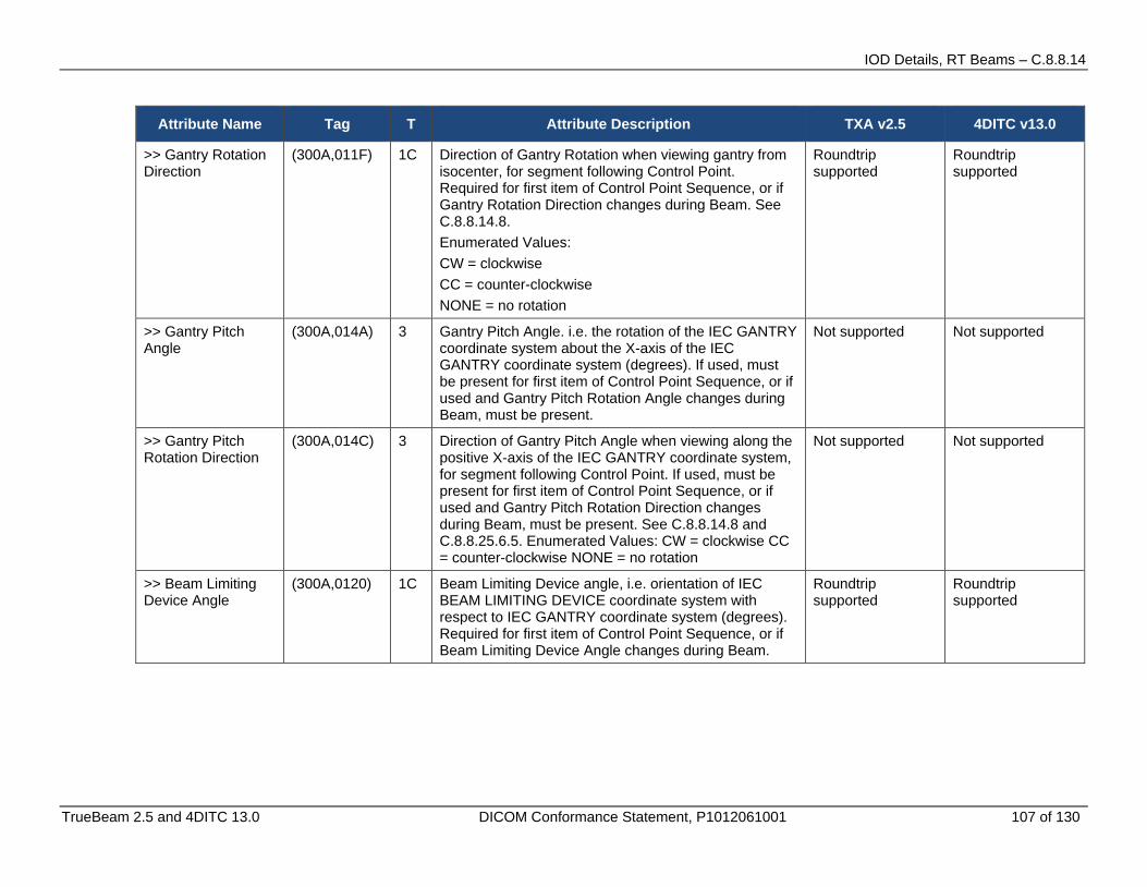
IOD Details, RT Beams – C.8.8.14
TrueBeam 2.5 and 4DITC 13.0 DICOM Conformance Statement, P1012061001 107 of 130
Attribute Name Tag T Attribute Description TXA v2.5 4DITC v13.0
>> Gantry Rotation Direction
(300A,011F) 1C Direction of Gantry Rotation when viewing gantry from isocenter, for segment following Control Point. Required for first item of Control Point Sequence, or if Gantry Rotation Direction changes during Beam. See C.8.8.14.8. Enumerated Values: CW = clockwise CC = counter-clockwise NONE = no rotation
Roundtrip supported
Roundtrip supported
>> Gantry Pitch Angle
(300A,014A) 3 Gantry Pitch Angle. i.e. the rotation of the IEC GANTRY coordinate system about the X-axis of the IEC GANTRY coordinate system (degrees). If used, must be present for first item of Control Point Sequence, or if used and Gantry Pitch Rotation Angle changes during Beam, must be present.
Not supported Not supported
>> Gantry Pitch Rotation Direction
(300A,014C) 3 Direction of Gantry Pitch Angle when viewing along the positive X-axis of the IEC GANTRY coordinate system, for segment following Control Point. If used, must be present for first item of Control Point Sequence, or if used and Gantry Pitch Rotation Direction changes during Beam, must be present. See C.8.8.14.8 and C.8.8.25.6.5. Enumerated Values: CW = clockwise CC = counter-clockwise NONE = no rotation
Not supported Not supported
>> Beam Limiting Device Angle
(300A,0120) 1C Beam Limiting Device angle, i.e. orientation of IEC BEAM LIMITING DEVICE coordinate system with respect to IEC GANTRY coordinate system (degrees). Required for first item of Control Point Sequence, or if Beam Limiting Device Angle changes during Beam.
Roundtrip supported
Roundtrip supported
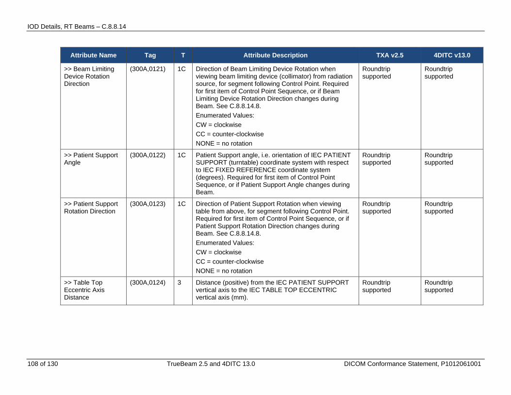
IOD Details, RT Beams – C.8.8.14
108 of 130 TrueBeam 2.5 and 4DITC 13.0 DICOM Conformance Statement, P1012061001
Attribute Name Tag T Attribute Description TXA v2.5 4DITC v13.0
>> Beam Limiting Device Rotation Direction
(300A,0121) 1C Direction of Beam Limiting Device Rotation when viewing beam limiting device (collimator) from radiation source, for segment following Control Point. Required for first item of Control Point Sequence, or if Beam Limiting Device Rotation Direction changes during Beam. See C.8.8.14.8. Enumerated Values: CW = clockwise CC = counter-clockwise NONE = no rotation
Roundtrip supported
Roundtrip supported
>> Patient Support Angle
(300A,0122) 1C Patient Support angle, i.e. orientation of IEC PATIENT SUPPORT (turntable) coordinate system with respect to IEC FIXED REFERENCE coordinate system (degrees). Required for first item of Control Point Sequence, or if Patient Support Angle changes during Beam.
Roundtrip supported
Roundtrip supported
>> Patient Support Rotation Direction
(300A,0123) 1C Direction of Patient Support Rotation when viewing table from above, for segment following Control Point. Required for first item of Control Point Sequence, or if Patient Support Rotation Direction changes during Beam. See C.8.8.14.8. Enumerated Values: CW = clockwise CC = counter-clockwise NONE = no rotation
Roundtrip supported
Roundtrip supported
>> Table Top Eccentric Axis Distance
(300A,0124) 3 Distance (positive) from the IEC PATIENT SUPPORT vertical axis to the IEC TABLE TOP ECCENTRIC vertical axis (mm).
Roundtrip supported
Roundtrip supported
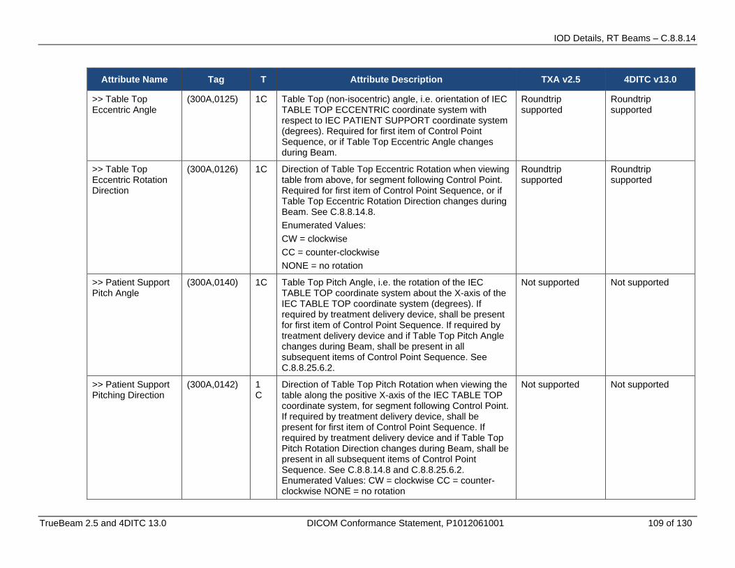
IOD Details, RT Beams – C.8.8.14
TrueBeam 2.5 and 4DITC 13.0 DICOM Conformance Statement, P1012061001 109 of 130
Attribute Name Tag T Attribute Description TXA v2.5 4DITC v13.0
>> Table Top Eccentric Angle
(300A,0125) 1C Table Top (non-isocentric) angle, i.e. orientation of IEC TABLE TOP ECCENTRIC coordinate system with respect to IEC PATIENT SUPPORT coordinate system (degrees). Required for first item of Control Point Sequence, or if Table Top Eccentric Angle changes during Beam.
Roundtrip supported
Roundtrip supported
>> Table Top Eccentric Rotation Direction
(300A,0126) 1C Direction of Table Top Eccentric Rotation when viewing table from above, for segment following Control Point. Required for first item of Control Point Sequence, or if Table Top Eccentric Rotation Direction changes during Beam. See C.8.8.14.8. Enumerated Values: CW = clockwise CC = counter-clockwise NONE = no rotation
Roundtrip supported
Roundtrip supported
>> Patient Support Pitch Angle
(300A,0140) 1C Table Top Pitch Angle, i.e. the rotation of the IEC TABLE TOP coordinate system about the X-axis of the IEC TABLE TOP coordinate system (degrees). If required by treatment delivery device, shall be present for first item of Control Point Sequence. If required by treatment delivery device and if Table Top Pitch Angle changes during Beam, shall be present in all subsequent items of Control Point Sequence. See C.8.8.25.6.2.
Not supported Not supported
>> Patient Support Pitching Direction
(300A,0142) 1 C
Direction of Table Top Pitch Rotation when viewing the table along the positive X-axis of the IEC TABLE TOP coordinate system, for segment following Control Point. If required by treatment delivery device, shall be present for first item of Control Point Sequence. If required by treatment delivery device and if Table Top Pitch Rotation Direction changes during Beam, shall be present in all subsequent items of Control Point Sequence. See C.8.8.14.8 and C.8.8.25.6.2. Enumerated Values: CW = clockwise CC = counter-clockwise NONE = no rotation
Not supported Not supported
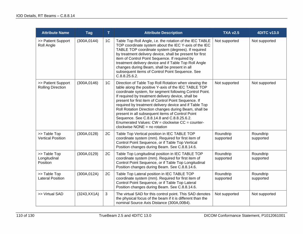
IOD Details, RT Beams – C.8.8.14
110 of 130 TrueBeam 2.5 and 4DITC 13.0 DICOM Conformance Statement, P1012061001
Attribute Name Tag T Attribute Description TXA v2.5 4DITC v13.0
>> Patient Support Roll Angle
(300A,0144) 1C Table Top Roll Angle, i.e. the rotation of the IEC TABLE TOP coordinate system about the IEC Y-axis of the IEC TABLE TOP coordinate system (degrees). If required by treatment delivery device, shall be present for first item of Control Point Sequence. If required by treatment delivery device and if Table Top Roll Angle changes during Beam, shall be present in all subsequent items of Control Point Sequence. See C.8.8.25.6.2.
Not supported Not supported
>> Patient Support Rolling Direction
(300A,0146) 1C Direction of Table Top Roll Rotation when viewing the table along the positive Y-axis of the IEC TABLE TOP coordinate system, for segment following Control Point. If required by treatment delivery device, shall be present for first item of Control Point Sequence. If required by treatment delivery device and if Table Top Roll Rotation Direction changes during Beam, shall be present in all subsequent items of Control Point Sequence. See C.8.8.14.8 and C.8.8.25.6.2. Enumerated Values: CW = clockwise CC = counter-clockwise NONE = no rotation
Not supported Not supported
>> Table Top Vertical Position
(300A,0128) 2C Table Top Vertical position in IEC TABLE TOP coordinate system (mm). Required for first item of Control Point Sequence, or if Table Top Vertical Position changes during Beam. See C.8.8.14.6.
Roundtrip supported
Roundtrip supported
>> Table Top Longitudinal Position
(300A,0129) 2C Table Top Longitudinal position in IEC TABLE TOP coordinate system (mm). Required for first item of Control Point Sequence, or if Table Top Longitudinal Position changes during Beam. See C.8.8.14.6.
Roundtrip supported
Roundtrip supported
>> Table Top Lateral Position
(300A,012A) 2C Table Top Lateral position in IEC TABLE TOP coordinate system (mm). Required for first item of Control Point Sequence, or if Table Top Lateral Position changes during Beam. See C.8.8.14.6.
Roundtrip supported
Roundtrip supported
>> Virtual SAD (3243,XX1A) 3 The virtual SAD for this control point. This SAD denotes the physical focus of the beam if it is different than the nominal Source Axis Distance (300A,00B4).
Not supported Not supported

IOD Details, RT Beams – C.8.8.14
TrueBeam 2.5 and 4DITC 13.0 DICOM Conformance Statement, P1012061001 111 of 130
Attribute Name Tag T Attribute Description TXA v2.5 4DITC v13.0
>> Table Top Pitch Angle
(300A,0140) 3 Table Top Pitch Angle, i.e. the rotation of the IEC TABLE TOP coordinate system about the X-axis of the IEC TABLE TOP coordinate system (degrees). If required by treatment delivery device, shall be present for first item of Control Point Sequence. If required by treatment delivery device and if Table Top Pitch Angle changes during Beam, shall be present in all subsequent items of Control Point Sequence
Beam will be valid if the tag is not available or has ‘0’ (zero) value. For non-zero values, beam will be marked as invalid.
Not supported
>> Table Top Pitch Rotation Direction
(300A,0142) 1C Direction of Table Top Pitch Rotation when viewing the table along the positive X-axis of the IEC TABLE TOP coordinate system, for segment following Control Point. If required by treatment delivery device, shall be present for first item of Control Point Sequence. If required by treatment delivery device and if Table Top Pitch Rotation Direction changes during Beam, shall be present in all subsequent items of Control Point Sequence. See C.8.8.14.8 and C.8.8.25.6.2. Enumerated Values: CW = clockwise CC = counter-clockwise NONE = no rotation
Beam will be valid if the tag is not available or has any value. This value will be read and ignored.
Not supported
>> Table Top Roll Angle
(300A,0144) 1C Table Top Roll Angle, i.e. the rotation of the IEC TABLE TOP coordinate system about the IEC Y-axis of the IEC TABLE TOP coordinate system (degrees). If required by treatment delivery device, shall be present for first item of Control Point Sequence. If required by treatment delivery device and if Table Top Roll Angle changes during Beam, shall be present in all subsequent items of Control Point Sequence
Beam will be valid if the tag is not available or has ‘0’ (zero) value. For non-zero values, beam will be marked as invalid.
Not supported
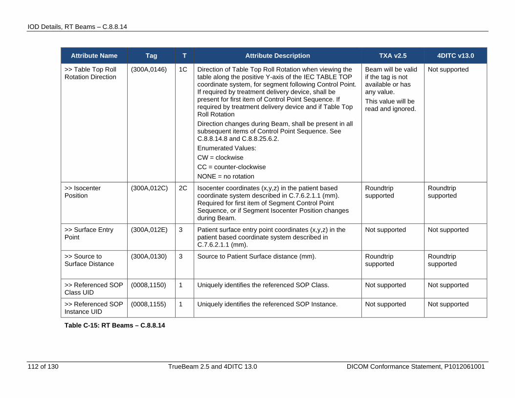
IOD Details, RT Beams – C.8.8.14
112 of 130 TrueBeam 2.5 and 4DITC 13.0 DICOM Conformance Statement, P1012061001
Attribute Name Tag T Attribute Description TXA v2.5 4DITC v13.0
>> Table Top Roll Rotation Direction
(300A,0146) 1C Direction of Table Top Roll Rotation when viewing the table along the positive Y-axis of the IEC TABLE TOP coordinate system, for segment following Control Point. If required by treatment delivery device, shall be present for first item of Control Point Sequence. If required by treatment delivery device and if Table Top Roll Rotation Direction changes during Beam, shall be present in all subsequent items of Control Point Sequence. See C.8.8.14.8 and C.8.8.25.6.2. Enumerated Values: CW = clockwise CC = counter-clockwise NONE = no rotation
Beam will be valid if the tag is not available or has any value. This value will be read and ignored.
Not supported
>> Isocenter Position
(300A,012C) 2C Isocenter coordinates (x,y,z) in the patient based coordinate system described in C.7.6.2.1.1 (mm). Required for first item of Segment Control Point Sequence, or if Segment Isocenter Position changes during Beam.
Roundtrip supported
Roundtrip supported
>> Surface Entry Point
(300A,012E) 3 Patient surface entry point coordinates (x,y,z) in the patient based coordinate system described in C.7.6.2.1.1 (mm).
Not supported Not supported
>> Source to Surface Distance
(300A,0130) 3 Source to Patient Surface distance (mm). Roundtrip supported
Roundtrip supported
>> Referenced SOP Class UID
(0008,1150) 1 Uniquely identifies the referenced SOP Class. Not supported Not supported
>> Referenced SOP Instance UID
(0008,1155) 1 Uniquely identifies the referenced SOP Instance. Not supported Not supported
Table C-15: RT Beams – C.8.8.14
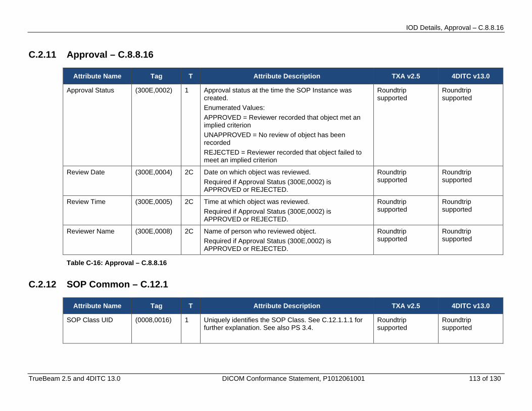
IOD Details, Approval – C.8.8.16
TrueBeam 2.5 and 4DITC 13.0 DICOM Conformance Statement, P1012061001 113 of 130
C.2.11 Approval – C.8.8.16
Attribute Name Tag T Attribute Description TXA v2.5 4DITC v13.0
Approval Status (300E,0002) 1 Approval status at the time the SOP Instance was created. Enumerated Values: APPROVED = Reviewer recorded that object met an implied criterion UNAPPROVED = No review of object has been recorded REJECTED = Reviewer recorded that object failed to meet an implied criterion
Roundtrip supported
Roundtrip supported
Review Date (300E,0004) 2C Date on which object was reviewed. Required if Approval Status (300E,0002) is APPROVED or REJECTED.
Roundtrip supported
Roundtrip supported
Review Time (300E,0005) 2C Time at which object was reviewed. Required if Approval Status (300E,0002) is APPROVED or REJECTED.
Roundtrip supported
Roundtrip supported
Reviewer Name (300E,0008) 2C Name of person who reviewed object. Required if Approval Status (300E,0002) is APPROVED or REJECTED.
Roundtrip supported
Roundtrip supported
Table C-16: Approval – C.8.8.16
C.2.12 SOP Common – C.12.1
Attribute Name Tag T Attribute Description TXA v2.5 4DITC v13.0
SOP Class UID (0008,0016) 1 Uniquely identifies the SOP Class. See C.12.1.1.1 for further explanation. See also PS 3.4.
Roundtrip supported
Roundtrip supported

IOD Details, SOP Common – C.12.1
114 of 130 TrueBeam 2.5 and 4DITC 13.0 DICOM Conformance Statement, P1012061001
Attribute Name Tag T Attribute Description TXA v2.5 4DITC v13.0
SOP Instance UID (0008,0018) 1 Uniquely identifies the SOP Instance. See C.12.1.1.1 for further explanation. See also PS 3.4.
Roundtrip supported
Roundtrip supported
Specific Character Set
(0008,0005) 1C Character Set that expands or replaces the Basic Graphic Set. Required if an expanded or replacement character set is used. See C.12.1.1.2 for Defined Terms.
Roundtrip supported
Roundtrip supported
Instance Creation Date
(0008,0012) 3 Date the SOP Instance was created. Roundtrip supported
Roundtrip supported
Instance Creation Time
(0008,0013) 3 Time the SOP Instance was created. Roundtrip supported
Roundtrip supported
Instance Creator UID
(0008,0014) 3 Uniquely identifies device which created the SOP Instance.
Roundtrip supported
Roundtrip supported
Related General SOP Class UID
(0008,001A) 3 Uniquely identifies a Related General SOP Class for the SOP Class of this Instance. See PS 3.4.
Not supported Not supported
Original Specialized SOP Class UID
(0008,001B) 3 The SOP Class in which the Instance was originally encoded, but which has been replaced during a fall-back conversion to the current Related General SOP Class. See PS 3.4.
Not supported Not supported
Coding Scheme Identification Sequence
(0008,0110) 3 Sequence of items that map values of Coding Scheme Designator (0008,0102) to an external coding system registration, or to a private or local coding scheme. One or more items may be present in the sequence.
Not supported Not supported
> Coding Scheme Designator
(0008,0102) 1 The value of a Coding Scheme Designator, used in this SOP Instance, which is being mapped.
Not supported Not supported

IOD Details, SOP Common – C.12.1
TrueBeam 2.5 and 4DITC 13.0 DICOM Conformance Statement, P1012061001 115 of 130
Attribute Name Tag T Attribute Description TXA v2.5 4DITC v13.0
> Coding Scheme Registry
(0008,0112) 1C The name of the external registry where further definition of the identified coding scheme may be obtained. Required if coding scheme is registered. Defined term: HL7
Not supported Not supported
> Coding Scheme UID
(0008,010C) 1C The coding scheme UID identifier. Required if coding scheme is identified by an ISO 8824 object identifier compatible with the UI VR.
Not supported Not supported
> Coding Scheme External ID
(0008,0114) 2C The coding scheme identifier as defined in an external registry. Required if coding scheme is registered and Coding Scheme UID (0008,010C) is not present.
Not supported Not supported
> Coding Scheme Name
(0008,0115) 3 The coding scheme full common name Not supported Not supported
> Coding Scheme Version
(0008,0103) 3 The coding scheme version associated with the Coding Scheme Designator (0008,0102).
Not supported Not supported
> Responsible Organization
(0008,0116) 3 Name of the organization responsible for the Coding Scheme. May include organizational contact information.
Not supported Not supported

IOD Details, SOP Common – C.12.1
116 of 130 TrueBeam 2.5 and 4DITC 13.0 DICOM Conformance Statement, P1012061001
Attribute Name Tag T Attribute Description TXA v2.5 4DITC v13.0
Timezone Offset From UTC
(0008,0201) 3 Contains the offset from UTC to the timezone for all DA and TM Attributes present in this SOP Instance. Encoded as an ASCII string in the format "&ZZZZ". The components of this string, from left to right, are & = "+" or "-", and ZZZZ = Hours and Minutes of offset. Notes: 1. This encoding is the same as described in PS 3.5 for the DT Value Representation. 2. This Attribute does not apply to values with a DT Value Representation, which may contain an explicitly encoded timezone. 3. The corrected time may cross a 24 hour boundary. For example, if Local Time = 1.00 a.m. and Offset = +0200, then UTC = 11.00 p.m. (23.00) the day before. 4. The "+" sign may not be omitted. Time earlier than UTC is expressed as a negative offset. Note: For example: UTC = 5.00 a.m. Local Time = 3.00 a.m. Offset = -0200 The local timezone offset is undefined if this Attribute is absent.
Not supported Not supported
Contributing Equipment Sequence
(0018,A001) 3 Sequence of Items containing descriptive attributes of related equipment which has contributed to the acquisition, creation or modification of the composite instance. One or more Items may be included in this Sequence. See C.12.1.1.5 for further explanation.
Not supported Not supported
> Purpose of Reference Code Sequence
(0040,A170) 1 Describes the purpose for which the related equipment is being reference. Only a single Item shall be permitted in this sequence. See C.12.1.1.5 for further explanation.
Not supported Not supported
>> Code Value (0008,0100) 1C See Section 8.1. Required if a sequence item is present.
Not supported Not supported
>> Coding Scheme Designator
(0008,0102) 1C See Section 8.2. Required if a sequence item is present.
Not supported Not supported
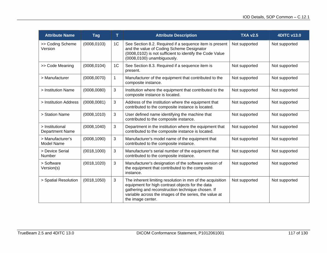
IOD Details, SOP Common – C.12.1
TrueBeam 2.5 and 4DITC 13.0 DICOM Conformance Statement, P1012061001 117 of 130
Attribute Name Tag T Attribute Description TXA v2.5 4DITC v13.0
>> Coding Scheme Version
(0008,0103) 1C See Section 8.2. Required if a sequence item is present and the value of Coding Scheme Designator (0008,0102) is not sufficient to identify the Code Value (0008,0100) unambiguously.
Not supported Not supported
>> Code Meaning (0008,0104) 1C See Section 8.3. Required if a sequence item is present.
Not supported Not supported
> Manufacturer (0008,0070) 1 Manufacturer of the equipment that contributed to the composite instance.
Not supported Not supported
> Institution Name (0008,0080) 3 Institution where the equipment that contributed to the composite instance is located.
Not supported Not supported
> Institution Address (0008,0081) 3 Address of the institution where the equipment that contributed to the composite instance is located.
Not supported Not supported
> Station Name (0008,1010) 3 User defined name identifying the machine that contributed to the composite instance.
Not supported Not supported
> Institutional Department Name
(0008,1040) 3 Department in the institution where the equipment that contributed to the composite instance is located.
Not supported Not supported
> Manufacturer’s Model Name
(0008,1090) 3 Manufacturer's model name of the equipment that contributed to the composite instance.
Not supported Not supported
> Device Serial Number
(0018,1000) 3 Manufacturer's serial number of the equipment that contributed to the composite instance.
Not supported Not supported
> Software Version(s)
(0018,1020) 3 Manufacturer's designation of the software version of the equipment that contributed to the composite instance.
Not supported Not supported
> Spatial Resolution (0018,1050) 3 The inherent limiting resolution in mm of the acquisition equipment for high contrast objects for the data gathering and reconstruction technique chosen. If variable across the images of the series, the value at the image center.
Not supported Not supported
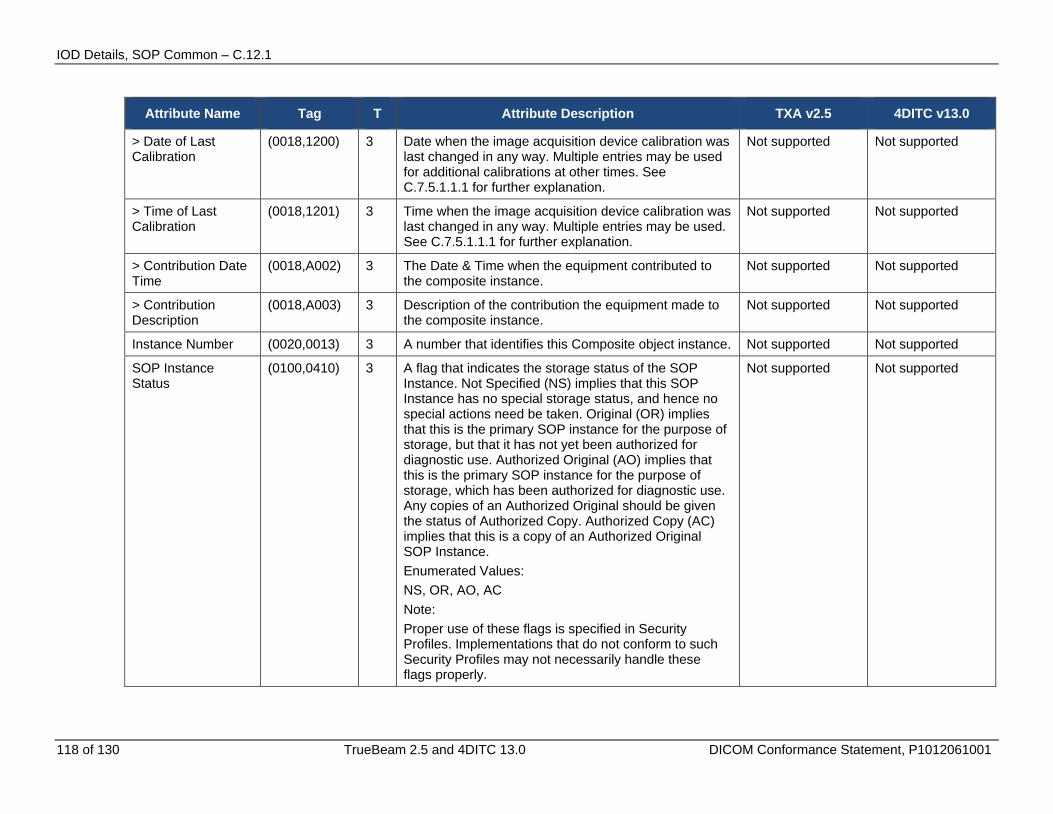
IOD Details, SOP Common – C.12.1
118 of 130 TrueBeam 2.5 and 4DITC 13.0 DICOM Conformance Statement, P1012061001
Attribute Name Tag T Attribute Description TXA v2.5 4DITC v13.0
> Date of Last Calibration
(0018,1200) 3 Date when the image acquisition device calibration was last changed in any way. Multiple entries may be used for additional calibrations at other times. See C.7.5.1.1.1 for further explanation.
Not supported Not supported
> Time of Last Calibration
(0018,1201) 3 Time when the image acquisition device calibration was last changed in any way. Multiple entries may be used. See C.7.5.1.1.1 for further explanation.
Not supported Not supported
> Contribution Date Time
(0018,A002) 3 The Date & Time when the equipment contributed to the composite instance.
Not supported Not supported
> Contribution Description
(0018,A003) 3 Description of the contribution the equipment made to the composite instance.
Not supported Not supported
Instance Number (0020,0013) 3 A number that identifies this Composite object instance. Not supported Not supported
SOP Instance Status
(0100,0410) 3 A flag that indicates the storage status of the SOP Instance. Not Specified (NS) implies that this SOP Instance has no special storage status, and hence no special actions need be taken. Original (OR) implies that this is the primary SOP instance for the purpose of storage, but that it has not yet been authorized for diagnostic use. Authorized Original (AO) implies that this is the primary SOP instance for the purpose of storage, which has been authorized for diagnostic use. Any copies of an Authorized Original should be given the status of Authorized Copy. Authorized Copy (AC) implies that this is a copy of an Authorized Original SOP Instance. Enumerated Values: NS, OR, AO, AC Note: Proper use of these flags is specified in Security Profiles. Implementations that do not conform to such Security Profiles may not necessarily handle these flags properly.
Not supported Not supported
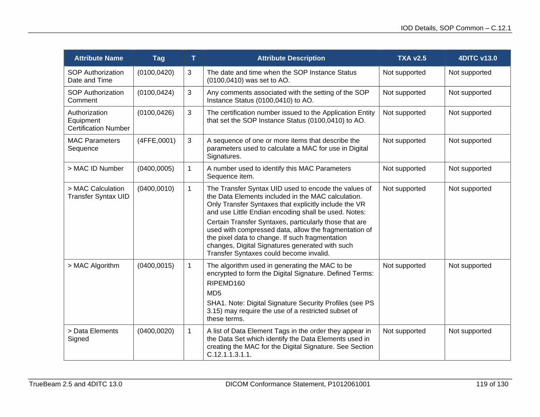
IOD Details, SOP Common – C.12.1
TrueBeam 2.5 and 4DITC 13.0 DICOM Conformance Statement, P1012061001 119 of 130
Attribute Name Tag T Attribute Description TXA v2.5 4DITC v13.0
SOP Authorization Date and Time
(0100,0420) 3 The date and time when the SOP Instance Status (0100,0410) was set to AO.
Not supported Not supported
SOP Authorization Comment
(0100,0424) 3 Any comments associated with the setting of the SOP Instance Status (0100,0410) to AO.
Not supported Not supported
Authorization Equipment Certification Number
(0100,0426) 3 The certification number issued to the Application Entity that set the SOP Instance Status (0100,0410) to AO.
Not supported Not supported
MAC Parameters Sequence
(4FFE,0001) 3 A sequence of one or more items that describe the parameters used to calculate a MAC for use in Digital Signatures.
Not supported Not supported
> MAC ID Number (0400,0005) 1 A number used to identify this MAC Parameters Sequence item.
Not supported Not supported
> MAC Calculation Transfer Syntax UID
(0400,0010) 1 The Transfer Syntax UID used to encode the values of the Data Elements included in the MAC calculation. Only Transfer Syntaxes that explicitly include the VR and use Little Endian encoding shall be used. Notes: Certain Transfer Syntaxes, particularly those that are used with compressed data, allow the fragmentation of the pixel data to change. If such fragmentation changes, Digital Signatures generated with such Transfer Syntaxes could become invalid.
Not supported Not supported
> MAC Algorithm (0400,0015) 1 The algorithm used in generating the MAC to be encrypted to form the Digital Signature. Defined Terms: RIPEMD160 MD5 SHA1. Note: Digital Signature Security Profiles (see PS 3.15) may require the use of a restricted subset of these terms.
Not supported Not supported
> Data Elements Signed
(0400,0020) 1 A list of Data Element Tags in the order they appear in the Data Set which identify the Data Elements used in creating the MAC for the Digital Signature. See Section C.12.1.1.3.1.1.
Not supported Not supported
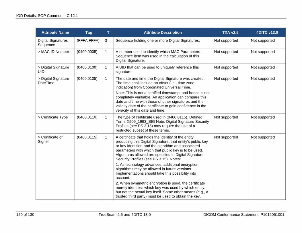
IOD Details, SOP Common – C.12.1
120 of 130 TrueBeam 2.5 and 4DITC 13.0 DICOM Conformance Statement, P1012061001
Attribute Name Tag T Attribute Description TXA v2.5 4DITC v13.0
Digital Signatures Sequence
(FFFA,FFFA) 3 Sequence holding one or more Digital Signatures. Not supported Not supported
> MAC ID Number (0400,0005) 1 A number used to identify which MAC Parameters Sequence item was used in the calculation of this Digital Signature.
Not supported Not supported
> Digital Signature UID
(0400,0100) 1 A UID that can be used to uniquely reference this signature.
Not supported Not supported
> Digital Signature DateTime
(0400,0105) 1 The date and time the Digital Signature was created. The time shall include an offset (i.e., time zone indication) from Coordinated Universal Time. Note: This is not a certified timestamp, and hence is not completely verifiable. An application can compare this date and time with those of other signatures and the validity date of the certificate to gain confidence in the veracity of this date and time.
Not supported Not supported
> Certificate Type (0400,0110) 1 The type of certificate used in (0400,0115). Defined Term: X509_1993_SIG Note: Digital Signature Security Profiles (see PS 3.15) may require the use of a restricted subset of these terms.
Not supported Not supported
> Certificate of Signer
(0400,0115) 1 A certificate that holds the identity of the entity producing this Digital Signature, that entity's public key or key identifier, and the algorithm and associated parameters with which that public key is to be used. Algorithms allowed are specified in Digital Signature Security Profiles (see PS 3.15). Notes: 1. As technology advances, additional encryption algorithms may be allowed in future versions. Implementations should take this possibility into account. 2. When symmetric encryption is used, the certificate merely identifies which key was used by which entity, but not the actual key itself. Some other means (e.g., a trusted third party) must be used to obtain the key.
Not supported Not supported

IOD Details, SOP Common – C.12.1
TrueBeam 2.5 and 4DITC 13.0 DICOM Conformance Statement, P1012061001 121 of 130
Attribute Name Tag T Attribute Description TXA v2.5 4DITC v13.0
> Signature (0400,0120) 1 The MAC generated as described in Section 12.2.1.1 and encrypted using the algorithm, parameters, and private key associated with the Certificate of the Signer (0400,0115). See Section C.12.1.1.3.1.2.
Not supported Not supported
> Certified Timestamp Type
(0400,0305) 1C The type of certified timestamp used in the Certified Timestamp (0400,0310) Attribute. Required if Certified Timestamp (0400,0310) is present. Defined Terms: CMS_TSP û Internet X.509 Public Key Infrastructure Time Stamp Protocol Note: Digital Signature Security Profiles (see PS 3.15) may require the use of a restricted subset of these terms.
Not supported Not supported
> Certified Timestamp
(0400,0310) 3 A certified timestamp of the Digital Signature (0400,0120) Attribute Value, which shall be obtained when the Digital Signature is created. See Section C.12.1.1.3.1.3.
Not supported Not supported
Encrypted Attributes Sequence
(0400,0500) 1C Sequence of Items containing encrypted DICOM data. One or more Items shall be present. Required if application level confidentiality is needed and certain recipients are allowed to decrypt all or portions of the Encrypted Attributes Data Set. See C.12.1.1.4.1.
Not supported Not supported
> Encrypted Content Transfer Syntax UID
(0400,0510) 1 Transfer Syntax used to encode the encrypted content. Only Transfer Syntaxes that explicitly include the VR and use Little Endian encoding shall be used.
Not supported Not supported
> Encrypted Content
(0400,0520) 1 Encrypted data. See C.12.1.1.4.2. Not supported Not supported
HL7 Structured Document Reference Sequence
(0040,A390) 1C Sequence of items defining mapping and/or access mechanism for HL7 Structured Documents referenced from the current SOP Instance. One or more Items may be included in this sequence. See C.12.1.1.6. Required if HL7 Structured Documents are referenced within the Instance.
Not supported Not supported
> Referenced SOP Class UID
(0008,1150) 1 Unique identifier for the class of HL7 Structured Document.
Not supported Not supported
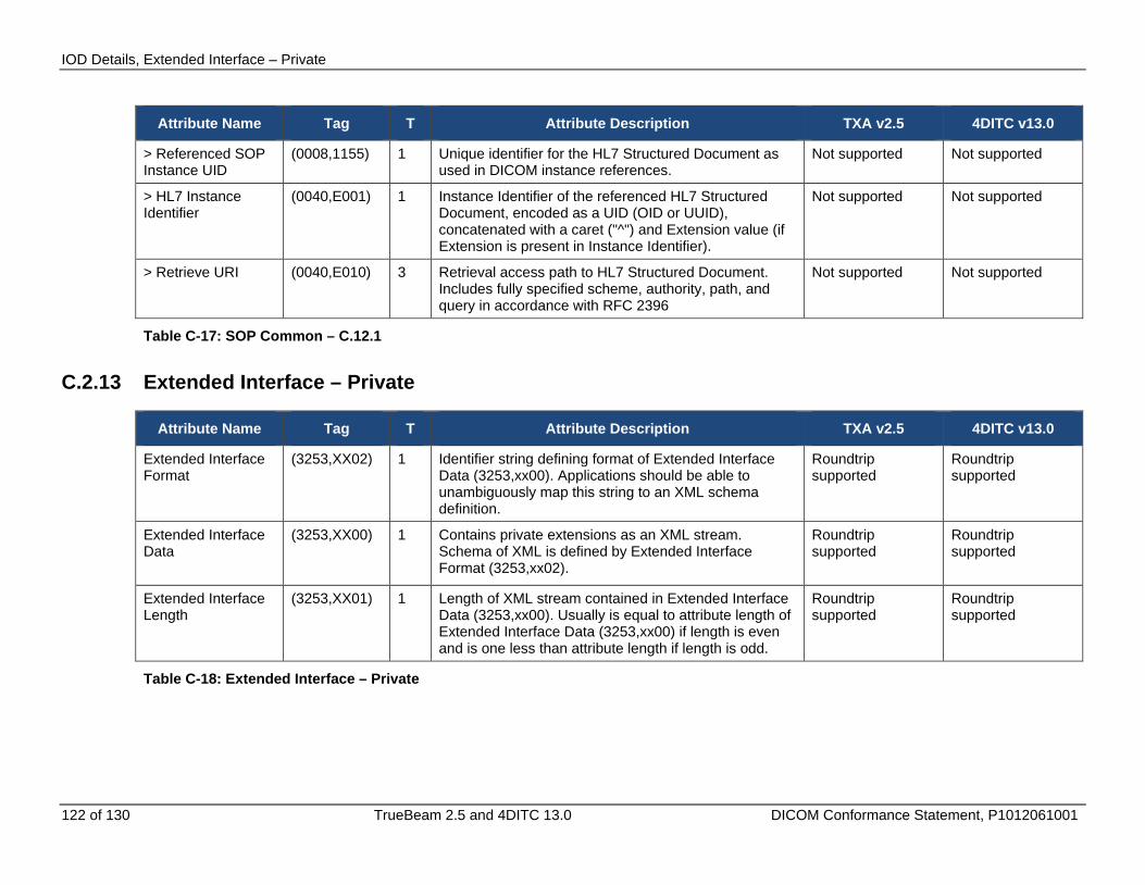
IOD Details, Extended Interface – Private
122 of 130 TrueBeam 2.5 and 4DITC 13.0 DICOM Conformance Statement, P1012061001
Attribute Name Tag T Attribute Description TXA v2.5 4DITC v13.0
> Referenced SOP Instance UID
(0008,1155) 1 Unique identifier for the HL7 Structured Document as used in DICOM instance references.
Not supported Not supported
> HL7 Instance Identifier
(0040,E001) 1 Instance Identifier of the referenced HL7 Structured Document, encoded as a UID (OID or UUID), concatenated with a caret ("^") and Extension value (if Extension is present in Instance Identifier).
Not supported Not supported
> Retrieve URI (0040,E010) 3 Retrieval access path to HL7 Structured Document. Includes fully specified scheme, authority, path, and query in accordance with RFC 2396
Not supported Not supported
Table C-17: SOP Common – C.12.1
C.2.13 Extended Interface – Private
Attribute Name Tag T Attribute Description TXA v2.5 4DITC v13.0
Extended Interface Format
(3253,XX02) 1 Identifier string defining format of Extended Interface Data (3253,xx00). Applications should be able to unambiguously map this string to an XML schema definition.
Roundtrip supported
Roundtrip supported
Extended Interface Data
(3253,XX00) 1 Contains private extensions as an XML stream. Schema of XML is defined by Extended Interface Format (3253,xx02).
Roundtrip supported
Roundtrip supported
Extended Interface Length
(3253,XX01) 1 Length of XML stream contained in Extended Interface Data (3253,xx00). Usually is equal to attribute length of Extended Interface Data (3253,xx00) if length is even and is one less than attribute length if length is odd.
Roundtrip supported
Roundtrip supported
Table C-18: Extended Interface – Private
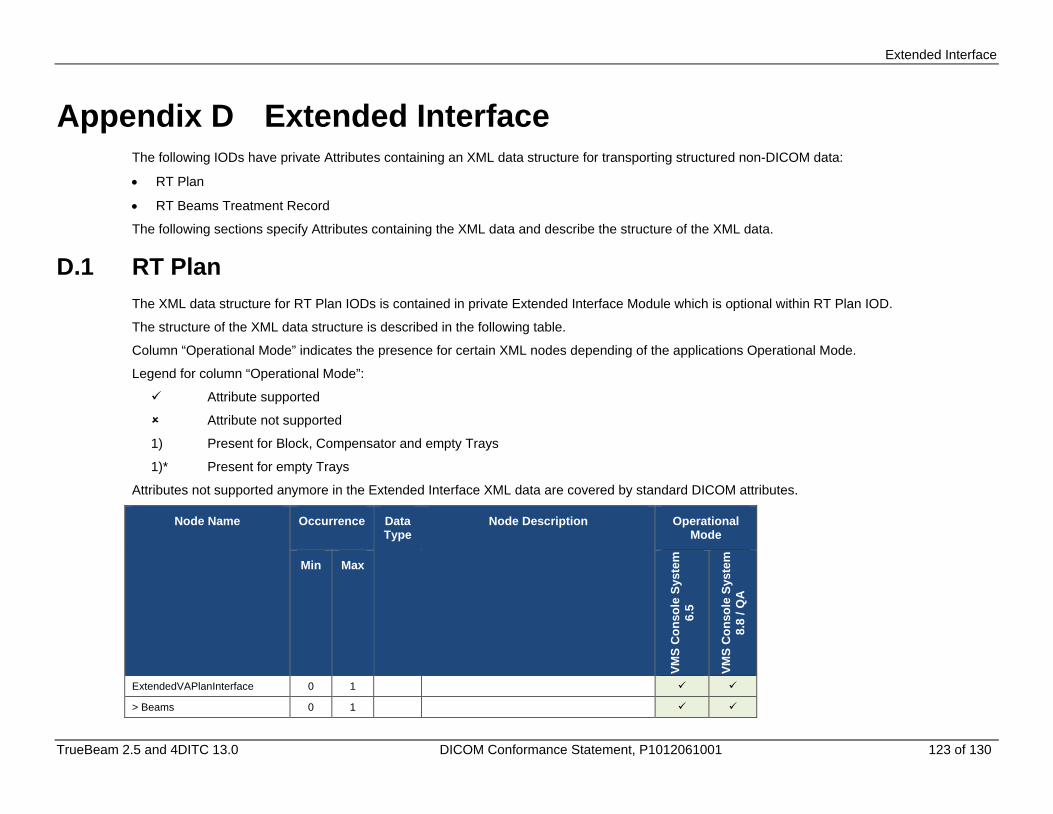
Extended Interface
TrueBeam 2.5 and 4DITC 13.0 DICOM Conformance Statement, P1012061001 123 of 130
Appendix D Extended Interface The following IODs have private Attributes containing an XML data structure for transporting structured non-DICOM data:
• RT Plan
• RT Beams Treatment Record
The following sections specify Attributes containing the XML data and describe the structure of the XML data.
D.1 RT Plan The XML data structure for RT Plan IODs is contained in private Extended Interface Module which is optional within RT Plan IOD.
The structure of the XML data structure is described in the following table.
Column “Operational Mode” indicates the presence for certain XML nodes depending of the applications Operational Mode.
Legend for column “Operational Mode”:
Attribute supported
Attribute not supported
1) Present for Block, Compensator and empty Trays
1)* Present for empty Trays
Attributes not supported anymore in the Extended Interface XML data are covered by standard DICOM attributes.
Node Name Occurrence Data Type
Node Description Operational Mode
Min Max
VMS
Con
sole
Sys
tem
6.
5
VMS
Con
sole
Sys
tem
8.
8 / Q
A
ExtendedVAPlanInterface 0 1
> Beams 0 1
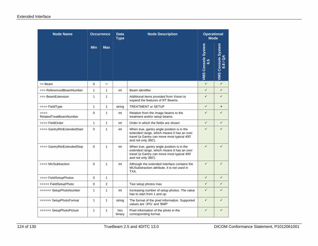
Extended Interface
124 of 130 TrueBeam 2.5 and 4DITC 13.0 DICOM Conformance Statement, P1012061001
Node Name Occurrence Data Type
Node Description Operational Mode
Min Max
VMS
Con
sole
Sys
tem
6.
5
VMS
Con
sole
Sys
tem
8.
8 / Q
A
>> Beam 0 ∞
>>> ReferencedBeamNumber 1 1 int Beam identifier
>>> BeamExtension 1 1 Additional items provided from Vision to expand the features of RT Beams.
>>>> FieldType 1 1 string TREATMENT or SETUP
>>>> RelatedTreatBeamNumber
0 1 int Relation from the image beams to the treatment and/or setup beams.
>>>> FieldOrder 1 1 int Order in which the fields are shown
>>>> GantryRtnExtendedStart 0 1 int When true, gantry angle position is in the extended range, which means it has an over travel (a Gantry can move most typical 400' and not only 360').
>>>> GantryRtnExtendedStop 0 1 int When true, gantry angle position is in the extended range, which means it has an over travel (a Gantry can move most typical 400' and not only 360').
>>>> MUSubtraction 0 1 int Although the extended interface contains the MUSubstraction attribute, it is not used in TXA.
>>>> FieldSetupPhotos 0 1
>>>>> FieldSetupPhoto 0 2 Two setup photos max
>>>>>> SetupPhotoNumber 1 1 int Increasing number of setup photos. The value has to start from 1 and up.
>>>>>> SetupPhotoFormat 1 1 string The format of the pixel information. Supported values are 'JPG' and 'BMP'
>>>>>> SetupPhotoPicture 1 1 hex binary
Pixel information of the photo in the corresponding format.
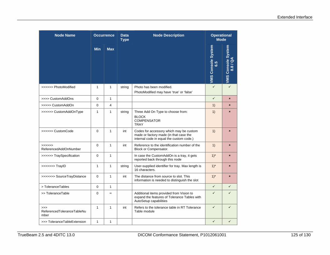
Extended Interface
TrueBeam 2.5 and 4DITC 13.0 DICOM Conformance Statement, P1012061001 125 of 130
Node Name Occurrence Data Type
Node Description Operational Mode
Min Max
VMS
Con
sole
Sys
tem
6.
5
VMS
Con
sole
Sys
tem
8.
8 / Q
A
>>>>>> PhotoModified 1 1 string Photo has been modified. PhotoModified may have ‘true’ or ‘false’
>>>> CustomAddOns 0 1
>>>>> CustomAddOn 0 4 1)
>>>>>> CustomAddOnType 1 1 string Three Add On Type to choose from: BLOCK COMPENSATOR TRAY
1)
>>>>>> CustomCode 0 1 int Codes for accessory which may be custom made or factory made (in that case the internal code in equal the custom code.)
1)
>>>>>> ReferencedAddOnNumber
0 1 int Reference to the identification number of the Block or Compensator.
1)
>>>>>> TraySpecification 0 1 In case the CustomAddOn is a tray, it gets reported back through this node
1)*
>>>>>>> TrayID 1 1 string User-supplied identifier for tray. Max length is 16 characters.
1)*
>>>>>>> SourceTrayDistance 0 1 int The distance from source to slot. This information is needed to distinguish the slot
1)*
> ToleranceTables 0 1
>> ToleranceTable 0 ∞ Additional items provided from Vision to expand the features of Tolerance Tables with AutoSetup capabilities
>>> ReferencedToleranceTableNumber
1 1 int Refers to the tolerance table in RT Tolerance Table module
>>> ToleranceTableExtension 1 1

Extended Interface
126 of 130 TrueBeam 2.5 and 4DITC 13.0 DICOM Conformance Statement, P1012061001
Node Name Occurrence Data Type
Node Description Operational Mode
Min Max
VMS
Con
sole
Sys
tem
6.
5
VMS
Con
sole
Sys
tem
8.
8 / Q
A
>>>> GantryRtnSetup 0 1 string Setup attributes may have following type: Automatic Manual Remote
>>>> CollRtnSetup 0 1 string
>>>> CollXSetup 0 1 string
>>>> CollYSetup 0 1 string
>>>> PatientSupportAngleSetup
0 1 string
>>>> CouchLngSetup 0 1 string
>>>> CouchVrtSetup 0 1 string
>>>> CouchLatSetup 0 1 string
>>>> TableTopEccentricAngleSetup
0 1 string
> DoseReferences 0 1
>> DoseReference 0 ∞
>>> ReferencedDoseReferenceNumber
1 1 int Reference to the identification number of the Dose Reference (300A,0012) in the RT Prescription module which is a representation of our reference point
>>> DoseReferenceExtension 1 1 Additional items provided from Vision to expand the features of reference points.
>>>> DailyDoseLimit 0 1 decimal
Unit is [Gy]
>>>> SessionDoseLimit 0 1 decimal
Unit is [Gy]
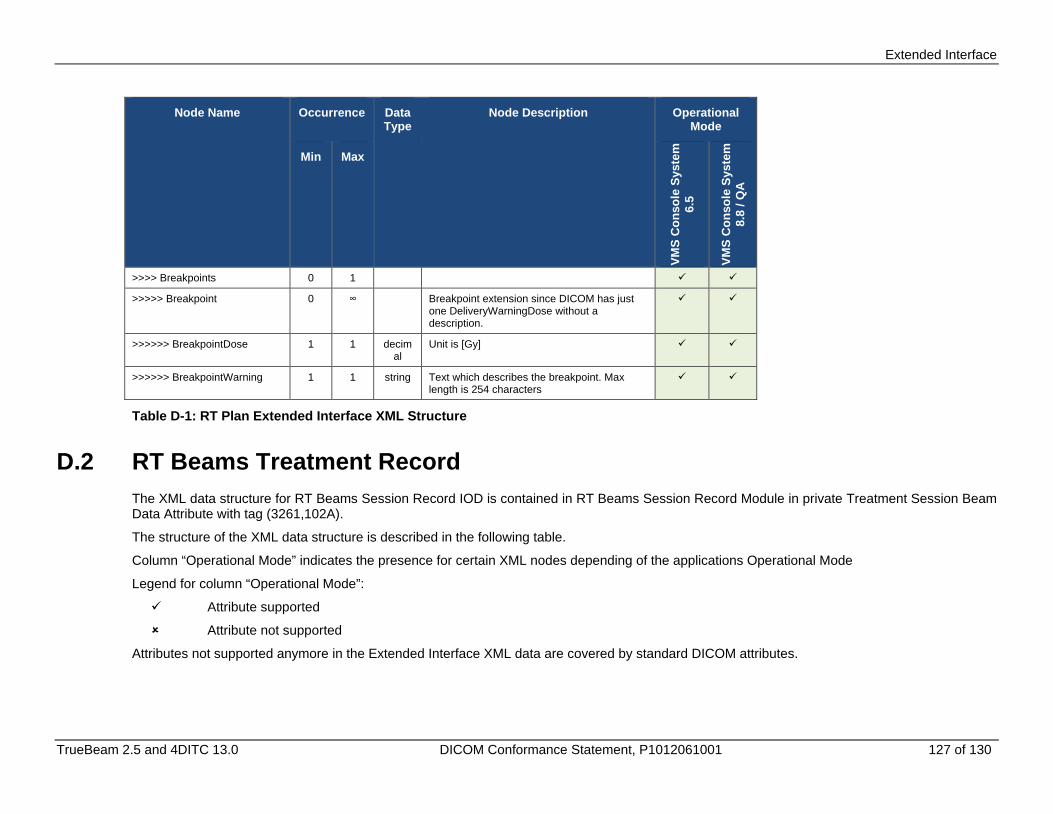
Extended Interface
TrueBeam 2.5 and 4DITC 13.0 DICOM Conformance Statement, P1012061001 127 of 130
Node Name Occurrence Data Type
Node Description Operational Mode
Min Max
VMS
Con
sole
Sys
tem
6.
5
VMS
Con
sole
Sys
tem
8.
8 / Q
A
>>>> Breakpoints 0 1
>>>>> Breakpoint 0 ∞ Breakpoint extension since DICOM has just one DeliveryWarningDose without a description.
>>>>>> BreakpointDose 1 1 decimal
Unit is [Gy]
>>>>>> BreakpointWarning 1 1 string Text which describes the breakpoint. Max length is 254 characters
Table D-1: RT Plan Extended Interface XML Structure
D.2 RT Beams Treatment Record The XML data structure for RT Beams Session Record IOD is contained in RT Beams Session Record Module in private Treatment Session Beam Data Attribute with tag (3261,102A).
The structure of the XML data structure is described in the following table.
Column “Operational Mode” indicates the presence for certain XML nodes depending of the applications Operational Mode
Legend for column “Operational Mode”:
Attribute supported
Attribute not supported
Attributes not supported anymore in the Extended Interface XML data are covered by standard DICOM attributes.
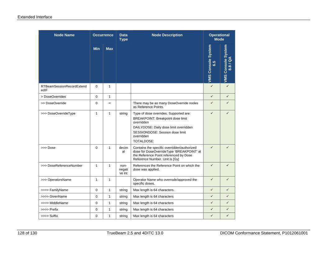
Extended Interface
128 of 130 TrueBeam 2.5 and 4DITC 13.0 DICOM Conformance Statement, P1012061001
Node Name Occurrence Data Type
Node Description Operational Mode
Min Max
VMS
Con
sole
Sys
tem
6.
5
VMS
Con
sole
Sys
tem
8.
8 / Q
A
RTBeamSessionRecordExtendedIF
0 1
> DoseOverrides 0 1
>> DoseOverride 0 ∞ There may be as many DoseOverride nodes as Reference Points.
>>> DoseOverrideType 1 1 string Type of dose overrides. Supported are: BREAKPOINT: Breakpoint dose limit overridden DAILYDOSE: Daily dose limit overridden SESSIONDOSE: Session dose limit overridden TOTALDOSE:
>>> Dose 0 1 decimal
Contains the specific overridden/authorized dose for DoseOverrideType ‘BREAKPOINT’ at the Reference Point referenced by Dose Reference Number. Unit is [Gy]
>>> DoseReferenceNumber 1 1 non-negative int
References the Reference Point on which the dose was applied.
>>> OperatorsName 1 1 Operator Name who overrode/approved the specific doses.
>>>> FamilyName 0 1 string Max length is 64 characters.
>>>> GivenName 0 1 string Max length is 64 characters
>>>> MiddleName 0 1 string Max length is 64 characters
>>>> Prefix 0 1 string Max length is 64 characters
>>>> Suffix 0 1 string Max length is 64 characters

Extended Interface
TrueBeam 2.5 and 4DITC 13.0 DICOM Conformance Statement, P1012061001 129 of 130
Node Name Occurrence Data Type
Node Description Operational Mode
Min Max
VMS
Con
sole
Sys
tem
6.
5
VMS
Con
sole
Sys
tem
8.
8 / Q
A
> TraySpecifications 0 1
>> TraySpecification 1 ∞ As many nodes as tray applied for the treated beam.
>>> TrayID 1 1 string That's the parameter which needs to be defined when a tray is defined/acquired. Max length is 16 characters
>>> SourceTrayDistance 0 1 int Radiation Source to attachment edge of tray assembly (mm).
> AdditionalOperators 0 1
>> OperatorsName 1 2 If the ‘Show Sign Off Dialog’ is checked in ITAdmin -> MachineConfiguration -> Preferences, the Sign Off Dialog will be shown after closing the patient. Three OperatorsName may be entered in this dialog. The first OperatorsName will be sent through the standard attribute Operator Name (0008,1070) in the RT Beams Session Record module, the remaining two names if available will be sent here in the Extended Interface
>>> FamilyName 0 1 string Max length is 64 characters.
>>> GivenName 0 1 string Max length is 64 characters
>>> MiddleName 0 1 string Max length is 64 characters
>>> Prefix 0 1 string Max length is 64 characters
>>> Suffix 0 1 string Max length is 64 characters
Table D-2: RT Beams Treatment Record Extended Interface XML Structure
Extended Interface
130 of 130 TrueBeam 2.5 and 4DITC 13.0 DICOM Conformance Statement, P1012061001
(This page is intentionally left blank.)