Diatomic Cesium in a Diode-Pumped Alkali Laser...
43
Diatomic Cesium in a Diode-Pumped Alkali Laser System Jamey Christy Eric Martinez Tanner Oakes Jake Smith Kendrick Walter Submitted in Partial Fulfillment of the Requirements for the Bachelor of Science in Electrical Engineering New Mexico Institute of Mining and Technology Department of Electrical Engineering May, 2008
Transcript of Diatomic Cesium in a Diode-Pumped Alkali Laser...

Diatomic Cesium in a Diode-Pumped Alkali Laser System
Jamey ChristyEric MartinezTanner OakesJake Smith
Kendrick Walter
Submitted in Partial Fulfillmentof the Requirements for the
Bachelor of Science in Electrical Engineering
New Mexico Institute of Mining and TechnologyDepartment of Electrical Engineering
May, 2008

Abstract
Diode Pumped Alkali Laser (DPAL) systems combine the positive characteristics of chemical
and diode lasers. These systems create a laser that is compact and efficient, while working
well at high temperatures and high powers. In conjunction with the Air Force Research
Laboratory (AFRL), an attempt was made to improve DPAL technology by using a diatomic
alkali metal as a gain medium. By switching to the diatomic species, it was theorized that
the system would be able take advantage of the diatomic’s wider absorption spectrum. This
would better match the line width of the diode pump and improve the power scalability.
Unfortunately, diatomic cesium will not lase due to very high input power requirements,
partially due to quenching, and pre-disassociation affects. However, during testing it was
discovered that diatomic cesium works as a relaxing agent for atomic rubidium.
In typical DPAL systems, ethane is used for a relaxing agent. This is creates problems
in current DPAL systems because ethane does not work well at high temperatures or high
powers because it burns and creates a tar-like coating inside the cell. The discovery that
diatomic cesium can be used as a relaxing agent, without having the negative effects of
ethane at high temperatures, allows the ethane to be replaced in rubidium based DPAL
systems. This addition greatly increases power scaling and efficiency.
Fully investigating this discovery is beyond the scope of this project, but the following
actions are recommended. First is testing different ratios of diatomic cesium to atomic
rubidium in the chemical cell to find the optimum ratio. Additional research is also needed
into the electro-physics occurring inside the diatomic cesium/atomic rubidium cell, which
may lead to additional discoveries with different combinations of alkali metals and diatomic
molecules for future DPAL systems.
Contents
1 Introduction 5
1.1 Current Laser Technology . . . . . . . . . . . . . . . . . . . . . . . . . . . . 5
1.2 DPAL Technology . . . . . . . . . . . . . . . . . . . . . . . . . . . . . . . . . 7
1.3 Purpose . . . . . . . . . . . . . . . . . . . . . . . . . . . . . . . . . . . . . . 9
1.3.1 Deliverables and Specifications . . . . . . . . . . . . . . . . . . . . . . 10
2 Literature Review 12
2.1 Laser Chemistry . . . . . . . . . . . . . . . . . . . . . . . . . . . . . . . . . . 12
2.1.1 Electron Transitions . . . . . . . . . . . . . . . . . . . . . . . . . . . 13
2.1.2 Laser Inversions . . . . . . . . . . . . . . . . . . . . . . . . . . . . . . 14
2.2 Alkali Lasers . . . . . . . . . . . . . . . . . . . . . . . . . . . . . . . . . . . . 14
2.3 Diatomic Cesium . . . . . . . . . . . . . . . . . . . . . . . . . . . . . . . . . 16
2.3.1 Energy Structure . . . . . . . . . . . . . . . . . . . . . . . . . . . . . 17
2.3.2 Spectrum . . . . . . . . . . . . . . . . . . . . . . . . . . . . . . . . . 18
3 Experiment Procedure 21
3.1 Experimental Setup . . . . . . . . . . . . . . . . . . . . . . . . . . . . . . . . 23
3.2 Pumping a Diatomic Cesium Cell . . . . . . . . . . . . . . . . . . . . . . . . 26
3.3 Lase with Atomic Rubidium . . . . . . . . . . . . . . . . . . . . . . . . . . . 28
3.4 Attempts to Lase Diatomic Cesium . . . . . . . . . . . . . . . . . . . . . . . 29
3.4.1 Pump with Ti:Sapph . . . . . . . . . . . . . . . . . . . . . . . . . . . 29
1

3.4.2 Maximize Power . . . . . . . . . . . . . . . . . . . . . . . . . . . . . 29
3.4.3 Add Diode Pump . . . . . . . . . . . . . . . . . . . . . . . . . . . . . 31
3.5 Cell Burn Out . . . . . . . . . . . . . . . . . . . . . . . . . . . . . . . . . . . 31
4 Results and Discussion 32
4.1 Unable to Lase Diatomic Cesium . . . . . . . . . . . . . . . . . . . . . . . . 32
4.2 Lase Atomic Rubidium . . . . . . . . . . . . . . . . . . . . . . . . . . . . . . 35
4.2.1 Diatomic Cesium as a Relaxant . . . . . . . . . . . . . . . . . . . . . 36
5 Conclusion 38
6 Future Work 39
2

List of Tables
1.1 Deliverables . . . . . . . . . . . . . . . . . . . . . . . . . . . . . . . . . . . . 10
1.2 Final System Specifications . . . . . . . . . . . . . . . . . . . . . . . . . . . 11
3
List of Figures
1.1 Diode Pumped Alkali Laser System . . . . . . . . . . . . . . . . . . . . . . . 7
1.2 DPAL Setup at AFRL . . . . . . . . . . . . . . . . . . . . . . . . . . . . . . 8
2.1 Periodic Table . . . . . . . . . . . . . . . . . . . . . . . . . . . . . . . . . . . 15
2.2 Alkali Laser Transitions . . . . . . . . . . . . . . . . . . . . . . . . . . . . . 15
2.3 Diatomic Cesium . . . . . . . . . . . . . . . . . . . . . . . . . . . . . . . . . 16
2.4 Diatomic Alkali Laser Transitions . . . . . . . . . . . . . . . . . . . . . . . . 18
2.5 Diatomic Cesium Spectrum . . . . . . . . . . . . . . . . . . . . . . . . . . . 19
2.6 Expected Emission Spectrum of Diatomic Cesium . . . . . . . . . . . . . . . 20
3.1 Expected Emission Spectrum of Diatomic Cesium . . . . . . . . . . . . . . . 21
3.2 Experimental Setup . . . . . . . . . . . . . . . . . . . . . . . . . . . . . . . . 23
3.3 Ti:Sapph Laser . . . . . . . . . . . . . . . . . . . . . . . . . . . . . . . . . . 25
3.4 Picture of Optical Setup . . . . . . . . . . . . . . . . . . . . . . . . . . . . . 26
3.5 Diatomic Cesium Laser Cell . . . . . . . . . . . . . . . . . . . . . . . . . . . 27
3.6 Diatomic Cesium Laser Cell . . . . . . . . . . . . . . . . . . . . . . . . . . . 28
3.7 Refined Telescope . . . . . . . . . . . . . . . . . . . . . . . . . . . . . . . . . 30
4.1 Curvature of a Laser’s Input/Output Power . . . . . . . . . . . . . . . . . . 33
4.2 Power In vs Power Out . . . . . . . . . . . . . . . . . . . . . . . . . . . . . . 34
4.3 Rubidium Lasing Inversion . . . . . . . . . . . . . . . . . . . . . . . . . . . . 35
4.4 Cell Temperature and its Effects on Cell Activity . . . . . . . . . . . . . . . 36
4

Chapter 1
Introduction
This paper presents the results and discoveries of a project involving the use of diatomic
alkali metals to improve Diode-Pumped Alkali Laser (DPAL) systems. It will focus first on
the original goal of using a diatomic alkali as a lasing gain medium in order to better utilize
the wide line width of currently available diode lasers. This concept was proved impractical
because lasing could not be achieved with test lasers that were significantly higher power
than the diode lasers that would be used in a real system. However, during the testing
process, it was discovered that diatomic cesium can be used as a relaxing agent for the
atomic rubidium laser system. While further testing of this discovery is outside the scope
of the project, the impact of the discovery and how it could be tested and utilized will be
discussed.
1.1 Current Laser Technology
Since their invention, lasers have had a great impact in creating many new commercial
devices. Optical storage, such as CDs and DVDs, allows large amounts of data to be stored
in compact form, while at the same time being easily and cheaply produced. In medicine,
lasers have been used to perform eye surgery that would be impossible with traditional
means. Lasers can also be used in other forms of surgery, making them less invasive and
5
allowing faster recovery. Heavy industry has adopted lasers, with lasers making extremely
precise cuts through some of the toughest materials. Despite this variety of applications,
there are areas in which a laser system is wanted, but there is no laser able to meet the
demands of the application. By looking at two of the most common types of commercial
lasers, diode lasers and chemical lasers, it is easy to see where these gaps are, and what a
new laser would have to do to fill those gaps.
In diode lasers, an electrical current is used to excite a semi-conducting material to release
a stream of photons. Diode lasers are relatively inexpensive, small in size, and require small
amounts of power to operate. This makes them ideal for consumer devices such as optical
storage. Their downfall is that the beam produced is of poor quality, and they have low
maximum power output.
A second major class of lasers is the chemical laser. In a chemical laser, a chemical gain
medium is excited to produce the laser beam. The gain medium can be a gas such as helium
or neon, a liquid such as dyes, or a crystalline solid such as ruby. These gain mediums are
capable of handling large amounts of power, and they produce a high quality beam with a
uniform wavefront. This makes them ideal as cutting lasers. Their downfall is that they are
expensive, large, and often require elaborate cooling systems that add to the cost, size and
complexity of the overall system. This limits them to semi-stationary locations for use with
specialized systems in order to justify the high cost.
In between these two classes of lasers exists a range of applications that needs a laser
that is small and inexpensive enough to be mass-produced for commercial devices but with a
medium power output in the hundreds of watts. One of the new technologies that attempts
to bridge this gap is Diode Pumped Alkali Laser (DPAL) technology.
6

1.2 DPAL Technology
The DPAL laser system creates a hybrid laser by combining a diode laser with a chemical
cell. This process balances advantages and disadvantages of each parent system, creating
a final system with properties between those of diode and chemical lasers. In the DPAL
system, a diode laser is used to pump a chemical cell containing vaporized alkali metal as
shown in Figure 1.1. The chemical cell acts as a gain medium, increasing the output power
of the system. DPAL systems have been successfully made with all of the alkali metals.
However, problems have been encountered in the implementation of the system that makes
them commercially inviable The goal of this project is to try to eliminate or reduce some of
these problems in an attempt to make DPAL systems commercially viable.
Figure 1.1: Diode Pumped Alkali Laser System
While there are several problems with current DPAL systems, there are two that will be
the focus of this project. The first is a mismatch between the line width of currently available
diode pumps and the atomic alkali’s absorption spectrum. The second is temperature and
power limits due to the use of ethane as a relaxing agent. Overcoming either one of these
problems would be a major step towards making DPAL systems commercially viable.
The first issue with current DPAL implementations is a mismatch between the diode
pump’s line width and the absorption line width of the alkali metals. The most advanced
diode lasers have a line width of 2 nm. However, the absorption line for a monatomic alkali
is on the order of two magnitudes narrower. The line width on the diode lasers can be
7

reduced by a factor of ten using an external grating, but this is still higher than desired, and
the grating increases the cost and complexity of the system [1]. Thus, even with the best
available technology, DPAL systems are highly inefficient. Figure 1.2 shows a typical DPAL
laser setup.
Figure 1.2: DPAL Setup at AFRL
The original project attempted to resolve this problem by switching from a monatomic
alkali to its diatomic form. This was done because the diatomic form adds additional energy
levels from the atoms ability to rotate and vibrate on the covalent bond between the two
atoms. These additional energy levels have the effect of broadening the absorption spectrum.
This creates a better match to the line width of the diode laser, making the system more
efficient.
The second problem with current DPAL implementations is the need for a relaxing agent
8

in order to make the alkali metals lase. The most common and currently most effective agent
is ethane gas. The problem with ethane is that it will break down if it is subjected to too
much heat or power. If the ethane does break down, it forms a tar like coating on the inside
of the cell, making the cell opaque, and essentially ruining the cell. This has two detrimental
effects on the system. First, it limits the amount of power that can be pumped into the
cell, and thereby the amount of power that can be output from the cell. Second, it limits
the temperature inside of the cell, reducing the energy of the alkali atoms, and ultimately
reducing the efficiency of the system. This immediately affects the power output, and it also
introduces a reliability problem. If the system operates below the threshold temperatures
and powers, the ethane could still break down if a ”hot spot” were to develop, which requires
the possibility of regular replacement of the cell.
While using the diatomic alkali as a gain medium was mainly being looked at for solving
the line width problem, it also has the secondary benefit of not requiring that ethane be
added as relaxing agent. This allowed much higher temperatures and input powers to be
used. While the original plan of using the diatomic alkali as a lasing gain medium was proved
not to work. It was discovered that diatomic cesium does act as a relaxant agent for atomic
rubidium. This will allow the replacement of the ethane in atomic rubidium DPAL systems,
allowing them to run at higher powers and temperatures.
1.3 Purpose
The purpose of this project was to improve DPAL technology. The original project looked
at enhancing three characteristics of a DPAL laser system. The first characteristic that was
examined was improving line width matching between the diode laser and the absorption
spectrum of the gain medium. This was accomplished by switching from atomic rubidium
to diatomic cesium. The second improvement was that diatomic cesium works without the
addition of an additional relaxing agent, increasing the power and temperature range of
9

the system. These are important because it would allow a laser system based off of this
design to use commercially available diode pumps instead of expensive test pumps. While
this design was proved to be inviable, a discovery was made that provides a new avenue for
future research. This discovery that diatomic cesium could be used as a relaxant for atomic
rubidium allows the system to be used at high temperatures than with the system using
ethane as the relaxing agent.
1.3.1 Deliverables and Specifications
Originally, the project was to build a system based around using diatomic cesium as a lasing
gain medium. The deliverables for such a system are shown in Table 1.1.
Deliverable Additional InformationFeasibility Study A feasibility study of an diatomic alkali laser using diode-
pumped alkali laser technology will be produced. Thestudy will entail assessing possible output wavelengths,determining pumping wavelengths, and determining theavailability of suitable diode pumps.
Diode Pump Laser System The laser will then incorporate a diode pump at the op-timal optical pumping wavelength as determined by thefeasibility study. The final laser system will be fine tunedand optimized. A demonstration of the system will thenbe given.
Table 1.1: Deliverables
Since the project was primarily a proof of concept, the final specifications for the system
were to show lasing with the diatomic cesium, with commercial considerations such as power
scaling to be left to later research. To be judged as successful, the final system was to meet
the specifications shown below in Table 1.2.
10
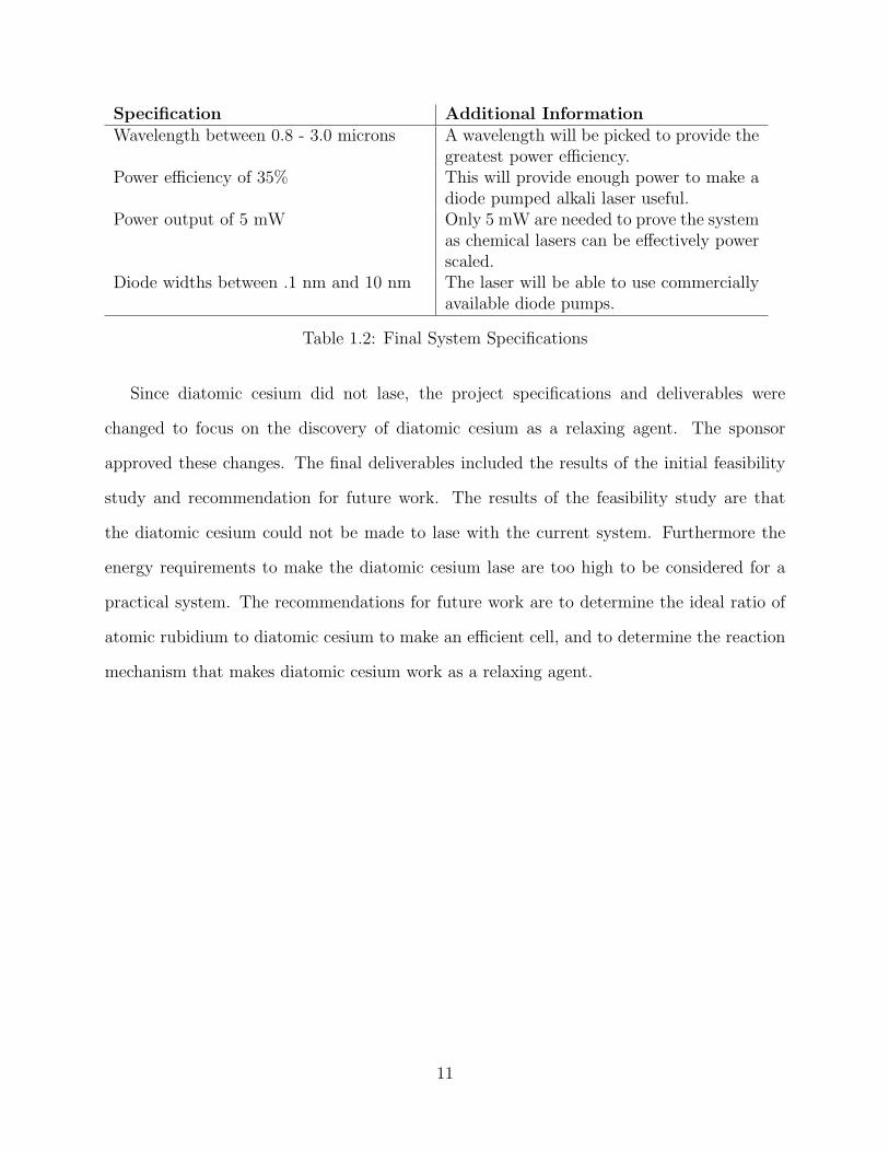
Specification Additional InformationWavelength between 0.8 - 3.0 microns A wavelength will be picked to provide the
greatest power efficiency.Power efficiency of 35% This will provide enough power to make a
diode pumped alkali laser useful.Power output of 5 mW Only 5 mW are needed to prove the system
as chemical lasers can be effectively powerscaled.
Diode widths between .1 nm and 10 nm The laser will be able to use commerciallyavailable diode pumps.
Table 1.2: Final System Specifications
Since diatomic cesium did not lase, the project specifications and deliverables were
changed to focus on the discovery of diatomic cesium as a relaxing agent. The sponsor
approved these changes. The final deliverables included the results of the initial feasibility
study and recommendation for future work. The results of the feasibility study are that
the diatomic cesium could not be made to lase with the current system. Furthermore the
energy requirements to make the diatomic cesium lase are too high to be considered for a
practical system. The recommendations for future work are to determine the ideal ratio of
atomic rubidium to diatomic cesium to make an efficient cell, and to determine the reaction
mechanism that makes diatomic cesium work as a relaxing agent.
11

Chapter 2
Literature Review
There is a large amount of research dealing with the chemistry of lasers. The fundamental
laser principles are well understood, and current research focuses on new materials and better
pumping methods. Much of the theoretical background research behind diode-pumped alkali
lasers has been completed, and there is ongoing research being done on diatomic alkali gain
mediums.
2.1 Laser Chemistry
A laser is composed of an energy source, a series of optics, and a gain medium. Energy is
pumped from the energy source into the gain medium exciting electrons to a higher state. A
laser is formed when a population inversion is created and the excited electrons fall back to
a lower state releasing energy in the form of electromagnetic waves. A series of optics is used
to collimate the released energy into a beam. The energy source can be an electrical current,
bright light, a heat source, or even another laser. The power density of the energy pump is
more important than the overall output power. Power density is the amount of power over
an area. In the case of a laser pump source the power density can be increased by either
reducing the beam size by using a telescope, or by increasing the output power of the laser.
12

2.1.1 Electron Transitions
Atoms are composed of a nucleus and a number of electrons occupying discrete energy levels.
Each energy level an electron can occupy in an atom is defined by a set of quantum numbers.
To describe an energy level within an atom term symbols are used. Term symbols take the
form 2S+1LJ , L represents the total orbital angular momentum quantum number, 2S + 1
is the multiplicity of the term with S being the total spin quantum number, and J is the
total angular momentum quantum number of the energy level [2]. The electron structure of
diatomic molecules is more complex. The energy levels are still defined by term symbols but
the symbols take the form 2S+1∆+/−Ω,(g/u), with the +/- and g/u terms showing the symmetry
of the energy level [3]. Electrons can change energy levels by the absorption or emission of
a photon. The absorption of a photon causes an electron to move to a higher energy level,
and the emission of an electron causes an electron to a lower level. Because the energy levels
in an atom are discrete only photons with wavelengths corresponding to the difference of
energy between two states can be absorbed or emitted. The relationship between wavelength
and energy is shown in equation 2.1.
λ = hc/E (2.1)
where λ is the wavelength, h is Planck’s constant, c is the speed of light, and E is energy.
Often wavenumbers are used instead of energy and wavelength. Wavenumbers are equal to
1 over the wavelength.
Lasers involve at least two electron transitions called the pumping transition and the las-
ing transition. In the pumping transition photons with certain wavelength are used to excite
electrons to a higher energy state. The electrons then relax to a lower energy state emitting
a photon with a wavelength corresponding to the change of energy. These emitted photons
are amplified in an optical cavity and focused into a beam of collimated light. Electrons
will make some intermediate transitions between the pumping and lasing transitions. Lasers
13
with one intermediate transition are three level lasers, two intermediate transitions are four
level lasers [4]. The amount of energy lost during the intermediate transitions is one of the
factors in determining the efficiency of the laser, and is referred to as the quantum defect of
the laser.
2.1.2 Laser Inversions
In order to form a laser there needs to be more electrons in the excited states than in
the target lasing state. This situation is called a laser inversion. This requires that the
intermediate transitions happen faster than the pumping transition, leaving the highest
energy level open for another electron to be pumped into it. For some gain mediums, such
as atomic alkali gain mediums, a buffering gas must be added to increase the intermediate
transition rates. The electron loses energy due to collisions with the buffering gas and drops
to lower energy levels quicker than it would otherwise. It is also desired that the lasing
transition happen at a slower rate to ensure that there is time for multiple electrons to be
in excited states. If electrons fall to the target lasing level too quickly an inversion cannot
be formed, this is known as quenching.
2.2 Alkali Lasers
Alkali metals are the elements in the first column of the Periodic Table (Figure 2.1). The
alkali metals all have the same electronic structure of a single valence electron.
14

Figure 2.1: Periodic Table
This leads to a 2S1/2 ground energy level and to a 2P1/2 and 2P3/2 first and second excited
energy levels. The alkali is pumped to the 2P3/2 energy level called the D2 transition and
then relaxes to the 2P1/2 energy level, see Figure 2.2. From there the alkali then lases back
to the 2S1/2 ground level, called the D1 transition. The quantum defect of these materials is
quite small, 2% for Rb and 5% for Cs [4], therefore alkalis have the potential to make very
efficient lasing mediums.
Figure 2.2: Alkali Laser Transitions
Three issues must be overcome in order to lase an alkali metal [4]. First, the pumping
energy needs to be absorbed in the narrow D2 transition. Currently this is accomplished
by diffraction grating the diode pump laser to narrow its bandwidth, and using a relatively
15

long optical path through the cell to allow as much absorption volume as possible. Second,
the transition between the 2P3/2 and 2P1/2 levels needs to happen in an efficient and rapid
manner. This transition can be sped up by adding a small molecule gas such as ethane to
increase the collisional mixing rate by an order of magnitude. Third, the energy from the
D1 lasing transition needs to be efficiently extracted without burning a spectral hole in the
gain medium. This is caused by standing waves canceling each other out in the gain medium
and effectively reducing the gain of the medium at the lasing wavelength. To counter this
the vapor can be buffered by a noble gas to broaden out the D1 and D2 transitions which
disrupts the interference caused by the standing waves.
2.3 Diatomic Cesium
Diatomic cesium, shown in Figure 2.3, consists of two cesium atoms bonded together with
a covalent bond. The properties of the bond give rise to a more complex energy structure
than the energy structure of a single cesium atom. Due to the many energy levels available,
diatomic cesium has wide bands in certain regions of its spectrum.
Figure 2.3: Diatomic Cesium
The high number of energy levels allows many different wavelengths to be emitted. Each
wavelength is associated with a corresponding electron transition. Due to the high number
of electron transitions there are many energy levels that electrons can fall back to as they
relax, a process known as quenching, and time between transitions can be short. Electrons
16

pumped to the higher B energy levels can also escape and cause the diatomic molecule to
break apart. This is known as pre-dissociation, and it happens when the time need to escape
the bond is shorter than the relaxing time to a lower energy state. The high number of
states in diatomic cesium is both an advantage and a disadvantage.
2.3.1 Energy Structure
Diatomic cesium is formed by a covalent bond between two cesium atoms. The energy
levels of each atom overlap and create energy wells occupied by electrons. In addition to
the electronic energy levels there are additional energy levels caused by the vibration and
rotation of the atoms around the covalent bond. Diatomic cesium has a ground level of
X1Σ+g , a first excited energy level of A1Σ+
u and a second excited energy level of B1Πu [5].
Each of these levels is split into numerous sub energy levels by the vibrational and rotational
energy levels. The energy of each energy level can be approximated using equation 2.2 [6].
Constants for diatomic cesium can be found in [7].
T = Te + we (v + .5)− wexe (v + .5)2 + [Be − αe (v + .5)] J (J + 1) (2.2)
where T is the calculated wavenumber, Te is the wavenumber of the electronic transition, we
and wexe are vibrational kinematic constants, v is the vibrational energy level, Be and αe
are rotational kinematic constants, and J is the rotational energy level.
The wavelength associated between two transitions is determined by equation 2.3 [8]. The
bigger the energy gap between two transitions the shorter the wavelength of light emitted.
λ =1
T2 − T1
(2.3)
where λ is the wavelength of the resulting transition, and T2 and T1 are the wavenumbers of
each energy level.
Lasing with a diatomic cesium gain medium is similar to lasing with an atomic alkali
17
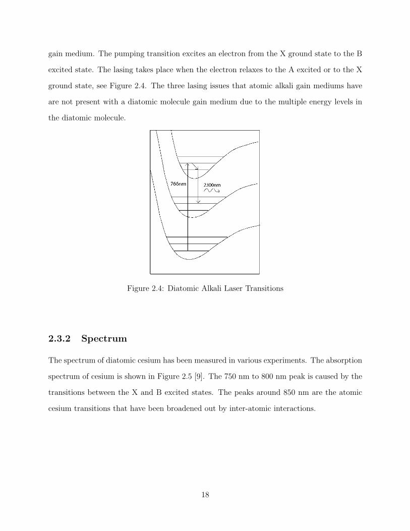
gain medium. The pumping transition excites an electron from the X ground state to the B
excited state. The lasing takes place when the electron relaxes to the A excited or to the X
ground state, see Figure 2.4. The three lasing issues that atomic alkali gain mediums have
are not present with a diatomic molecule gain medium due to the multiple energy levels in
the diatomic molecule.
Figure 2.4: Diatomic Alkali Laser Transitions
2.3.2 Spectrum
The spectrum of diatomic cesium has been measured in various experiments. The absorption
spectrum of cesium is shown in Figure 2.5 [9]. The 750 nm to 800 nm peak is caused by the
transitions between the X and B excited states. The peaks around 850 nm are the atomic
cesium transitions that have been broadened out by inter-atomic interactions.
18

Figure 2.5: Diatomic Cesium Spectrum
When pumped at 775 nm 780 nm and 785 nm, diatomic cesium emits the spectrum shown
in Figure 2.6 [10]. The largest peak in each spectrum is at the wavelength of the pumping
laser, and the rest of the peaks are emissions from diatomic cesium as the electrons relax to
lower energy levels. The intensity units are arbitrary and only give a relative measurement
of the peak’s intensity.
19

Figure 2.6: Expected Emission Spectrum of Diatomic Cesium
Peaks to the left of the pumping wavelength are toward the blue side, to the right are on
the red side. It is impossible to lase with peaks on the blue side. This indicates more energy
is coming out of the laser than is being put into the laser. Peaks toward the red side are the
viable lasing peaks.
20

Chapter 3
Experiment Procedure
Figure 3.1 shows the critical path that was followed in this project. The project was divided
into three main phases: Preparatory Works Phase, Test Pump Phase, and Max Power Phase.
Figure 3.1: Expected Emission Spectrum of Diatomic Cesium
The preparatory work phase consisted of determining the spectrum of diatomic cesium.
This was done by pumping the cell with a Ti:Sapph laser. Based on the results of this test
21
, three possible pumping wavelengths were selected for further examination in later phases.
These wavelengths are 757 nm, 765 nm, and 768 nm. Once this phase was completed, the
team moved onto the Test Pump Phase.
The Test Pump Phase consisted of building the optical system and optimizing it. During
this phase, several tests were done to try and lase with the diatomic cesium cell. All of
these tests proved unsuccessful, and it was determined that the next step was to increase
the amount of power being pumped into the cell. This led the project into the Max Power
Phase.
In the Max Power Phase, an additional diode pump was added to the optical setup. The
diode pump added an additional watt of input power into the cell. This additional power
was still not enough to make the diatomic cesium lase. However, during this test, atomic
rubidium was present as a contaminant and it was lasing without the ethane usually needed.
After further testing, diatomic cesium was acting as a relaxing agent for the atomic rubidium.
With these results, the project moved away from attempting to lase with the diatomic cesium
and towards recommending what to do with the discovery of diatomic cesium as a relaxing
agent.
The critical path also includes a timeline that shows when each specific phase of the
project was completed. The Prep Work Phase was completed on February 20, 2008, the Test
Pump Phase was completed on March 20, 2008, and the Max Power Phase was completed
on April 18, 2008.
Figure 3.1 also includes as the expenditure rate of the budget. The test equipment was
located at AFRL in Albuquerque, NM, so it was necessary to make trip to the lab in order
to work on the project. The 400 dollars of internal funds were used to cover some of the
travel cost from going from Socorro to Albuquerque.
The tasking is also described in Figure 3.1. The group collaborated and worked together
on the entire project. However, specific individuals led each key part of the project. The
legend on the bottom of the diagram indicates which individual led and co-led each portion
22

of the project. For example, the spectrum part was led by Tanner and the co-leader was
Eric.
3.1 Experimental Setup
The optical setup went through many revisions during the experimentation process. Fig-
ure 3.2 presents the basic design. The Ti:sapph system is fed with up to 15 Watts from the
diode-pumped solid-state Nd:YVO4 laser. This is then frequency doubled with a KTiOPO4,
or KTP crystal. The resultant output is the green 532 nm pump source for the Ti:Sapph
laser (Figure 3.3).
Figure 3.2: Experimental Setup
23

The Ti:Sapph was used because of its wavelength output adjustability using a birefringent
crystal system. Through these conversions, the output power of the Ti:Sapph was reduced
to a maximum of 3 Watts. It is important to note that the lasers progressively move toward
the red because electrons need to be pumped at least to the next shell in order to create an
inversion. The 1/2 Waveplate, to the right of the pump source, is a polarizer. This gives
the beam the correct orientation needed to travel correctly through the beam splitter. The
polarizer used was adjustable and when combined with the polarization beam splitter, it
could be used to adjust the power level. This method is more accurate and faster to use
than trying to adjust the Ti:sapph to have the desired output. The focusing lens seen below
was usually a set of optics setup as a telescope. They were used to bring the beam width
down to the theoretical minimum inside the cell. The PBS then acts as a one-way valve,
allowing the beam to go through the splitter on the way in, and then when it bounce off the
high reflector and goes back, acts as a mirror and deflects all the light towards the output
coupler. The oven was used to vaporize the cesium dimer inside of the cell and was typically
heated to 265 degrees Celsius, but some of the experiments were run at up to 300 degrees
Celsius. The output coupler and the high reflector comprised the sides of the lasing cavity,
and were changed based on the length of the cell so that the beam stayed focused through
the entire length.
24

Figure 3.3: Ti:Sapph Laser
Other optical components were part of the setup including irises, isolators, and periscopes.
Irises were used at numerous points to help in aligning the beam and to reduce the impacts
of reflections from other parts of the system. The isolator on the output of the Ti:Sapph
was used to protect the laser from back reflections. Two periscopes were implemented to
correctly align the beam one for the vertical detection the other for the lateral. When a
diode pump was added to this setup, an additional set of periscopes and PBS were added
to get both beams to follow the same path. In addition beam blocks were used to contain
the beam while adjustments were being made to the system, and a low power Helium-Neon
laser was used to check alignment of components
Figure 3.4 shows all of the components of the experimental setup. The periscope and
mirrors are towards the bottom right. They sent the laser from the Ti:Sapph through an
25

Figure 3.4: Picture of Optical Setup
iris for alignment purposes. Then, the laser went through a telescope, which has the lenses
placed far apart. The polarization beam splitter, high reflector, output coupler, and alkali
cell are all close to each other to minimize alignment errors. A CCD camera detects the
activity inside the cell, and the final laser after output coupler was sent to a power meter.
3.2 Pumping a Diatomic Cesium Cell
The first step in the testing process was to build the test cell and oven and to determine
the cells excitation in the region of interest. The initial diatomic cesium cell was four inches
long, and about an inch in diameter. The oven was constructed by placing the cell into a
metal shell, which was then wrapped with a heating tape. A thermocouple was placed next
26

to the cell to control its temperature.. A picture of the cell is shown below in Figure 3.5.
Figure 3.5: Diatomic Cesium Laser Cell
First, the cell was heated to 250C, and then it was pumped with the Ti:Sapph laser. The
Ti:Sapphs output was swept over the region of interest 750 nm to 800 nm. A CCD camera
looked through a hole in the side of the cell and measured the different wavelengths of light
inside the cell to display it on a computer monitor. The results with the most transition
levels for diatomic cesium are shown in Figure 3.6.
The top panel of Figure 3.6 shows the transition levels for when the cell was pumped
with a 757 nm wavelength, and heated to 266C. The large peak at 757 nm is due to the
Ti:Sapph pumping. This graph shows a large emission at 759 nm in comparison to the other
two graphs and observations. Since an electron emission is necessary to lase, the first graph
showed a possible wavelength and temperature for lasing. The middle panel shows higher
27

Figure 3.6: Diatomic Cesium Laser Cell
peaks farther away from the pumping wavelength. The bottom panel shows several emission
lines with relatively large magnitudes. Only the spectral lines to the right of the pumping
wavelength may be used for lasing because lasing in the gain medium occurs at a higher
wavelength than the pumping due to the transition energy levels.
3.3 Lase with Atomic Rubidium
To test that the experimental setup was working and to gain familiarity with the lasing
process, the system was first built and tested using atomic rubidium. A rubidium cell was
heated to around 200C, and it was pumped from the Ti:Sapph laser at 780 nm wavelength.
The system then lased at the expected 795 nm wavelength. With the correctly operating
28

system, the optical setup was optimized to improve the power efficiency. Then the cell was
replaced with a diatomic cesium cell.
3.4 Attempts to Lase Diatomic Cesium
In attempting to get the cesium dimer to lase, a procedure was used that was based off of
the previously successful attempt to build the atomic rubidium DPAL system. This process
benefited from use of the CCD camera, which allowed the conditions to be observed and
monitored inside of the cell. The test facility did not have the CDD camera when the atomic
rubidium DPAL was built, and the ability to observing the transitions greatly improved the
testing process.
3.4.1 Pump with Ti:Sapph
The particular model of Ti:Sapph that was used was the MBR-110. This is a broadband laser
that can be tuned from 650 nm to 1100 nm, but operate most efficiently at about 800 nm.
In these experiments the laser had a crystal installed that allowed for an adjustable output
wavelength from 750-820 nm. The first step was to determine an ideal cell temperature
and wavelength at which to lase at. A number of measurements were made at different
temperatures to determine the emission spectrum of diatomic cesium.
3.4.2 Maximize Power
Initial tests showed that the cesium dimer cells were being excited by the test system but
without enough power to actually produce the lasing threshold or inversion. First, the main
laser was increased to its maximum power determined by the Ti:Sapph laser. The next
step was to narrow the width of the beam to concentrate as much power as possible in the
smallest area. This was accomplished using a series of telescopes. The first telescope system
used first lens with a focal length of 250 mm, with the second lens placed so that the focal
29

points of the two lenses coincided. This process produces a collimated beam with the new
beam width proportional to the ratio of focal lengths of the two lenses. A series of telescopes
were used to decrease the beam width from one-half to one-forth and finally to one-eighth
its original size. This focusing still did not create a high enough power density to create the
laser. As a final step, one of the employees in the lab disassembled and cleaned the Ti:sapph
to increase its power back up to its original maximum, which became slightly degraded due
to dust and other imperfections.
Figure 3.7: Refined Telescope
In Figure 3.7, the lenses for the new telescope are shown. The laser from the Ti:Sapph
laser goes from right to left. First, it goes through an iris and then through the telescoping
lenses. After these focusing lenses, it goes to the polarizing beam splitter, alkali cell, high
reflector, and output coupler.
30
3.4.3 Add Diode Pump
In an attempt to further increase the power in the system, a diode pump was added to the
setup. The diode pump was from the Satur tiger series and has a 1 Watt output, 3 MHz line
width, and an ideal output wavelength of 780 nm. While this increase in the input power
of the cell did not cause diatomic cesium to lase, another discovery was found during this
process. This discovery was that there was atomic rubidium in the cell, and it was lasing
without the ethane usually needed as a relaxing agent.
3.5 Cell Burn Out
In order to improve the output of the cell, the oven temperature was increased multiple
times. The output power did increase as the temperature increased. However, when the
oven reached too high of a temperature, the cell burned out. Cesium is an extremely reactive
element; thus, it will react strongly with other elements. The cell walls were made out of
quartz glass which cesium will not readily react with. However, once the temperature of the
cell passed a certain threshold, the cesium was able to react with the crystal quartz in the
cell walls and left a brown residue on the inside of the cell. This ruined the cell, and further
testing was impossible.
31

Chapter 4
Results and Discussion
The project found that diatomic cesium does not work as a gain medium using the experi-
mental setup. One reason is that the power threshold for the alkali cell was never reached.
It was never saturated. This was true for multiple pumping wavelengths and beam sizes.
However, diatomic cesium works well as a relaxing agent for atomic rubidium. It allowed
the alkali rubidium lase even though there was only trace amounts of rubidium in the alkali
cell.
4.1 Unable to Lase Diatomic Cesium
Measurements of the power that was input into the oven versus the power that was present
on the output of the oven were taken. During this process, the Ti:Sapph laser was used.
The purpose of this procedure was to determine if the diatomic cesium cell was saturating.
Ideally, the laser’s input/output power should resemble the curve in Figure 4.1.
32
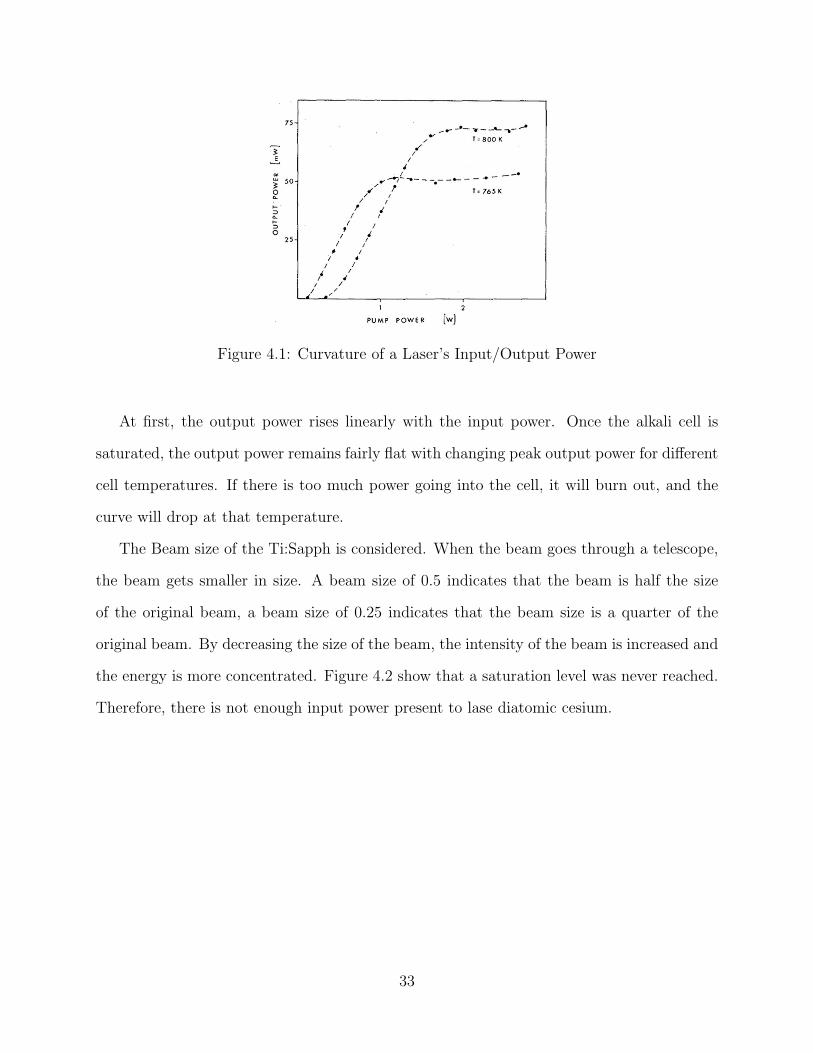
Figure 4.1: Curvature of a Laser’s Input/Output Power
At first, the output power rises linearly with the input power. Once the alkali cell is
saturated, the output power remains fairly flat with changing peak output power for different
cell temperatures. If there is too much power going into the cell, it will burn out, and the
curve will drop at that temperature.
The Beam size of the Ti:Sapph is considered. When the beam goes through a telescope,
the beam gets smaller in size. A beam size of 0.5 indicates that the beam is half the size
of the original beam, a beam size of 0.25 indicates that the beam size is a quarter of the
original beam. By decreasing the size of the beam, the intensity of the beam is increased and
the energy is more concentrated. Figure 4.2 show that a saturation level was never reached.
Therefore, there is not enough input power present to lase diatomic cesium.
33

Figure 4.2: Power In vs Power Out
Figure 4.2 shows pumping wavelengths of 765 nm and 757 nm with two beam sizes. The
plots compare the input power to the output power. As can be seen the line continues to
increase in a fairly linear fashion. If the plot had a drop off point then the diatomic cesium
could potentially lase.
Other research on lasing diatomic cesium has also concluded that diatomic cesium is not
a viable lasing medium [11]. Energy that is pumped into diatomic cesium is lost in two ways.
First, enough energy is being absorbed by the electrons to allow them to escape fragmenting
the molecule. As the vapor is in equilibrium the molecule can eventually reform, but the
absorbed energy is lost. Second, due to quenching the electrons fall back to random lower
energy states. This is seen as the multiple peaks in the emission spectrum as diatomic cesium
is pumped. Because much of the energy was being used in these two processes, very little
energy was available to create a laser.
34

4.2 Lase Atomic Rubidium
During the process of adding the diode pump laser to the setup it was found that atomic
rubidium was present in the cell. Figure 4.3 shows an inversion. This means that the Rb (795
nm) had a stronger magnitude that the pumping lasers (780 nm). Both the taller Ti:Sapph
and the shorter diode laser lines can be seen at 780 nm, just slightly at different wavelengths.
Figure 4.3: Rubidium Lasing Inversion
To verify that diatomic cesium was causing the atomic rubidium to lase the temperature
of the oven was slowly lowered. This is shown in Figure 4.4.
35

Figure 4.4: Cell Temperature and its Effects on Cell Activity
As the temperature decreased the emissions seen from both the diatomic cesium and
atomic rubidium also decreased. Atomic rubidium in an ethane environment will lase at
temperatures above 120C. When the temperature of the cell decreased to 180C, all emis-
sions ceased. This showed that without stimulation from the diatomic cesium the rubidium
in the cell can not lase.
4.2.1 Diatomic Cesium as a Relaxant
Diatomic Cesium creates an environment for atomic rubidium in which all three conditions
for rubidium to lase are fulfilled. Collisions between diatomic cesium molecules and rubidium
atoms causes the rubidium atoms to lose some of their energy. As a result, this speeds up
the intermediate energy transition. Diatomic cesium also broadens out the lasing transition
36

of rubidium thereby inhibiting a spectral hole from forming. In addition, diatomic cesium
absorbs the pumping energy that rubidium cannot absorb and some of that extra energy is
released at 780 nm providing more energy to the rubidium. The exact mechanisms involved
are not yet fully understood, and further research is necessary.
37
Chapter 5
Conclusion
There are several important conclusions to be drawn from the work done in this project. The
first is that despite best efforts, it is impossible to lase with diatomic cesium with the setup
used. Most of the energy pumped into diatomic cesium is lost in other transitions before a
lasing inversion can form. With a higher power system or the addition of a quenching gas
it may be possible to get the diatomic cesium to lase. However, such a system would be
impractical and provide little real benefit.
The second discovery was that diatomic cesium acts as a relaxing agent for atomic rubid-
ium based DPAL system. This possibility has never been explored before, and this will allow
the ethane currently being used to be replaced. This replacement will improve the quality
of the current systems in several key ways such as the ability to run at higher temperatures,
and higher input powers.
There is still work to done to fully utilize this discovery in current systems. There were
plans to investigate this property more extensively. Unfortunately, while testing the reaction
at higher temperatures, the cell was destroyed when the cesium metal reacted with the quartz
glass cell wall. Due to time and budgetary concerns, it was not possible to acquire another
test cell. Recommendations for future work will be included as to how to determine optimal
cell properties and investigate the interactions behind the discovery.
38
Chapter 6
Future Work
This project tapped the surface of the potential for using diatomic cesium for Diode-Pumped
Alkali Laser technology. Since this project showed diatomic cesium works well as a relaxant,
this new technology should be investigated more. The next step is to combine different
proportions of diatomic cesium and atomic rubidium into the same cell, and then test the
effectiveness.
The cell used for this project was supposed to contain 100% diatomic cesium according
the cell manufacturer. Tests show that it contained atomic rubidium, and this slight amount
in the cell was able to lase since diatomic cesium is a good relaxing agent. Therefore, only a
small percentage of atomic rubidium is needed. The exact amounts or relative percentages
are unknown because the amount inside the cell for the project remains unknown. One way
to figure out the required amount is to research the interaction between the diatomic cesium
molecules and rubidium atoms inside the cell.
Details about the chemistry inside an atomic rubidium and diatomic cesium cell are
unknown. Also, the reason that diatomic cesium is a good relaxant is unclear. These
topics should be investigated, and this research may lead to discoveries about using different
diatomic alkalis as a relaxant for atomic rubidium or cesium. Additionally, a possibility of
exploring similar results in other columns of the periodic table might be performed.
39
Bibliography
[1] T. A. Perschbacher, D. A. Hostutler, and T. M. Shay, “High-efficiency diode-pumped
rubidium laser: Experimental results,” presented at GCL-HPL. Copy was produced by
D. A. Hostutler.
[2] P. Atkins and J. de Paula, Physical Chemistry. New York, New York: Oxford University
Press, 2002.
[3] G. L. Miessler and D. A. Tarr, Inorganic Chemsitry. Upper Saddle River, New Jersey:
Pearson Education, 2004.
[4] W. F. Krupke, R. J. Beach, V. K. Kanz, S. A. Payne, and J. T. Early, “New class of
CW high-power diode-pumped alkali lasers (dpals),” in Proceedings of SPIE, 2004, pp.
7–17.
[5] B. Wellegehausen, “Optically pumped CW dimer lasers,” IEEE Journal of Quantum
Electronics, vol. QE-15, no. 10, pp. 1108–1130, Oct. 1979.
[6] G. Herzberg, Molecular Spectra and Molecular Structure I. Spectra of Diatomic
Molecules. Malabar, Florida: Krieger Publishing Company, 1989.
[7] A. D. Smirnov, “Calculation of the spectroscopic constants for the electronic states A,
B, C, D, and E of the cesium dimer,” Optics and Spectroscopy, vol. 102, no. 1, pp. 18–22,
Feb. 2006.
40

[8] P. F. Bernath, Spectra of Atoms and Molecules. New York, New York: Oxford Univer-
sity Press, 1995.
[9] S. Vdovic, D. Sarkisyan, and G. Pichler, “Absorption spectrum of rubidium and cesium
dimers by compact computer operated spectrometer,” Optics Communications, vol. 268,
pp. 58–63, June 2006.
[10] M. Terrell and M. F. Masters, “Laser spectroscopy of the cesium dimer as a physics
laboratory experiment,” American Journal of Physics, vol. 64, no. 9, pp. 1116–1120,
Sept. 1996.
[11] R. P. Benedict, Jr, “Investigation of diatomic cesium as a laser medium by absorp-
tion and fluorescence spectroscopy,” Ph.D. dissertation, Air Force Inst of Tech Wright-
Patterson AFB Ohio School of Engineering, June 1977.
41


![Modeling and analysis of an ultra-stable subluminal laser · the same mechanism as is used for realizing the conventional DPAL (Diode Pumped Alkali Laser) [22,23,24,25,26,27]. A spectrally](https://static.fdocuments.net/doc/165x107/5aff846b7f8b9af1148b5a09/modeling-and-analysis-of-an-ultra-stable-subluminal-laser-same-mechanism-as-is-used.jpg)