
Diaphragm Valves, LD Series (MS-01-172,...
8
www.swagelok.com Diaphragm Valves LD Series ■ Working pressures up to 300 psig (20.6 bar) ■ Shutoff, bulk-gas distribution, and isolation service ■ Cast, forged, and bar stock stainless steel body material ■ 1/4 to 1 in. and 12 to 25 mm end connections
Transcript of Diaphragm Valves, LD Series (MS-01-172,...

www.swagelok.com
Diaphragm Valves
LD Ser ies■ Working pressures up to 300 psig (20.6 bar)
■ Shutoff, bulk-gas distribution, and isolation service
■ Cast, forged, and bar stock stainless steel body material
■ 1/4 to 1 in. and 12 to 25 mm end connections
2 LD Series Diaphragm Valves
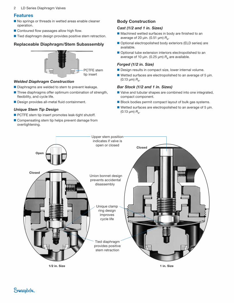
Replaceable Diaphragm/Stem Subassembly
Welded Diaphragm Construction■ Diaphragms are welded to stem to prevent leakage.
■ Three diaphragms offer optimum combination of strength, flexibility, and cycle life.
■ Design provides all-metal fluid containment.
Unique Stem Tip Design■ PCTFE stem tip insert promotes leak-tight shutoff.
■ Compensating stem tip helps prevent damage from overtightening.
Features■ No springs or threads in wetted areas enable cleaner
operation.
■ Contoured flow passages allow high flow.
■ Tied diaphragm design provides positive stem retraction.
Union bonnet design prevents accidental
disassembly
Upper stem position indicates if valve is
open or closed
Tied diaphragm provides positive stem retraction
1/2 in. Size 1 in. Size
Body Construction
Cast (1/2 and 1 in. Sizes)■ Machined wetted surfaces in body are finished to an
average of 20 µin. (0.51 µm) Ra.
■ Optional electropolished body exteriors (ELD series) are available.
■ Optional tube extension interiors electropolished to an average of 10 µin. (0.25 µm) Ra are available.
Forged (1/2 in. Size)■ Design results in compact size, lower internal volume.
■ Wetted surfaces are electropolished to an average of 5 µin. (0.13 µm) Ra.
Bar Stock (1/2 and 1 in. Sizes)■ Valve and tubular shapes are combined into one integrated,
compact component.
■ Block bodies permit compact layout of bulk gas systems.
■ Wetted surfaces are electropolished to an average of 5 µin. (0.13 µm) Ra.
Unique clamp ring design improves cycle life
Open
Closed
Closed
PCTFE stem tip insert

LD Series Diaphragm Valves 3
1
2
3
4
5
6
7
8
10
11
9a
9b
9c9d9e
9f
9
Materials of Construction
Testing
SC-11 ProcessEvery LD series diaphragm valve processed in accordance with Swagelok® Special Cleaning and Packaging (SC-11), MS-06-63, is helium leak tested to a maximum leak rate of 4 10–9 std cm3/s.
SC-01 ProcessEvery LD series diaphragm valve processed in accordance with Swagelok Ultrahigh-Purity Process Specification (SC-01), MS-06-61, is helium leak tested to a maximum leak rate of 1 10–9 std cm3/s.
Cleaning and Packaging
Cast-Body ValvesAll LD series cast-body diaphragm valves are cleaned and packaged in accordance with Swagelok Special Cleaning and Packaging (SC-11), MS-06-63, to ensure compliance with product cleanliness requirements stated in ASTM G93 Level C. Cleaning and packaging in accordance with Swagelok Ultrahigh-Purity Process Specification (SC-01), MS-06-61, is available as an option for ELD series cast-body valves.
Forged-Body and Bar Stock ValvesAll LD series forged-body and bar stock diaphragm valves are manufactured, cleaned, and packaged in accordance with Swagelok Ultrahigh-Purity Process Specification (SC-01), MS-06-61. Cleaning in accordance with Swagelok Special Cleaning and Packaging (SC-11), MS-06-63, to ensure compliance with product cleanliness requirements stated in ASTM G93 Level C is available as an option.
Wetted components listed in italics.
Cast-body 1/2 in. size shown.
Component
Valve Body
Cast Forged Bar Stock
Material Grade/ASTM Specification
1 Handle
Handle set screw
Polyester with 316 SS insert
Alloy steel
2 Bonnet nut Silver-plated 316 SS/A479
3 Thrust washer
Actuator bearing (1 in. size)
Bronze
High-carbon chrome
steel —
High-carbon chrome
steel
4 Actuator 416 SS/A582
5 Spring washer Alloy steel
6 Bonnet
Thrust washer (1 in. size)
Bonnet bearing (1 in. size)
316 SS/A479
Bronze
—
Bronze
High-carbon chrome
steel
High-carbon chrome
steel
7 Upper stem 316 SS/A479
8 Clamp ring Brass/B16
9 Diaphragm/stem subassembly See individual components below
9a Diaphragms (3) 316L SS/A240
9b Stem 316L SS/A479
9c Compression ring Virgin PTFE
9d Inner ring 316L SS/A479
9e Stem tip insert PCTFE/AMS 3650
9f Outer ring 316L SS/A479
10 Gasket PTFE-coated 316L SS/A240
11 Body CF3M/ A351
316L SS/ A182
316L SS/ A479
Swagelok tube fitting and pipe end connections
316 SS/ A479 — —
VCR® fitting end connections 316 SS/A479
Tube extensions 316 SS/A269
Lubricant Molybdenum disulfide-base paste and dry film, petroleum lubricating grease
4 LD Series Diaphragm Valves
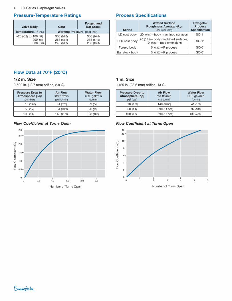
Flow Coefficient at Turns OpenFlow Coefficient at Turns Open
Number of Turns Open
Flow
Co
effic
ient
(C
v)
Number of Turns Open
Flow
Co
effic
ient
(C
v)
Pressure-Temperature Ratings Process Specifications
Flow Data at 70°F (20°C)
1/2 in. Size0.500 in. (12.7 mm) orifice, 2.8 Cv
1 in. Size1.125 in. (28.6 mm) orifice, 13 Cv
Valve Body Cast Forged and Bar Stock
Temperature, °F (°C) Working Pressure, psig (bar)
–20 (–28) to 100 (37) 200 (93) 300 (148)
300 (20.6) 265 (18.2) 240 (16.5)
300 (20.6) 255 (17.5) 230 (15.8)
Series
Wetted Surface Roughness Average (Ra)
µin. (µm) avg
Swagelok Process
Specification
LD cast body 20 (0.51)—body machined surfaces SC-11
ELD cast body 20 (0.51)—body machined surfaces; 10 (0.25)—tube extensions SC-11
Forged body 5 (0.13)—P process SC-01
Bar stock body 5 (0.13)—P process SC-01
Pressure Drop to Atmosphere (p)
psi (bar)
Air Flow std ft3/min (std L/min)
Water Flow U.S. gal/min
(L/min)
10 (0.68) 31 (870) 9 (34)
50 (3.4) 84 (2300) 20 (75)
100 (6.8) 148 (4100) 28 (100)
Pressure Drop to Atmosphere (p)
psi (bar)
Air Flow std ft3/min (std L/min)
Water Flow U.S. gal/min
(L/min)
10 (0.68) 140 (3900) 41 (150)
50 (3.4) 390 (11 000) 92 (340)
100 (6.8) 690 (19 500) 130 (490)
LD Series Diaphragm Valves 5
A
2.41 (61.2)
2.95 (74.9)
2.25 (57.2)
LD16 Series
A
4.35 (110)
5.12 (130)
4.00 (102)
Dimensions shown with Swagelok tube fitting nuts finger-tight.➀ See specifications ISO 7/1, BS EN 10226-1, DIN-2999, JIS B0203.
LD8 Series
No purge ports
A
B
A
Integral male VCR fittings
B
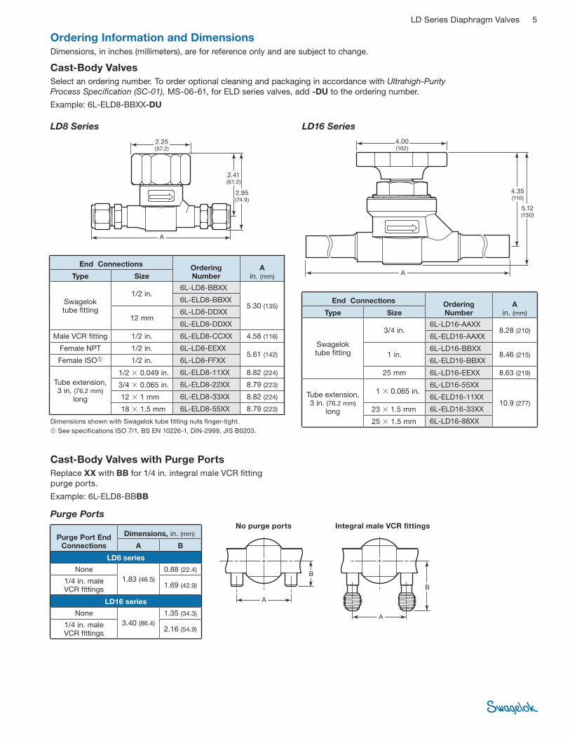
Ordering Information and DimensionsDimensions, in inches (millimeters), are for reference only and are subject to change.
Cast-Body ValvesSelect an ordering number. To order optional cleaning and packaging in accordance with Ultrahigh-Purity Process Specification (SC-01), MS-06-61, for ELD series valves, add -DU to the ordering number.
Example: 6L-ELD8-BBXX-DU
Purge Ports
Cast-Body Valves with Purge PortsReplace XX with BB for 1/4 in. integral male VCR fitting purge ports.
Example: 6L-ELD8-BBBB
End Connections Ordering Number
A in. (mm)Type Size
Swagelok tube fitting
1/2 in. 6L-LD8-BBXX
5.30 (135) 6L-ELD8-BBXX
12 mm 6L-LD8-DDXX
6L-ELD8-DDXX
Male VCR fitting 1/2 in. 6L-ELD8-CCXX 4.58 (116)
Female NPT 1/2 in. 6L-LD8-EEXX 5.61 (142)
Female ISO➀ 1/2 in. 6L-LD8-FFXX
Tube extension, 3 in. (76.2 mm)
long
1/2 0.049 in. 6L-ELD8-11XX 8.82 (224)
3/4 0.065 in. 6L-ELD8-22XX 8.79 (223)
12 1 mm 6L-ELD8-33XX 8.82 (224)
18 1.5 mm 6L-ELD8-55XX 8.79 (223)
End Connections Ordering Number
A in. (mm)Type Size
Swagelok tube fitting
3/4 in. 6L-LD16-AAXX
8.28 (210)6L-ELD16-AAXX
1 in. 6L-LD16-BBXX
8.46 (215)6L-ELD16-BBXX
25 mm 6L-LD16-EEXX 8.63 (219)
Tube extension, 3 in. (76.2 mm)
long
1 0.065 in. 6L-LD16-55XX
10.9 (277) 6L-ELD16-11XX
23 1.5 mm 6L-ELD16-33XX
25 1.5 mm 6L-LD16-88XX
Purge Port End Connections
Dimensions, in. (mm)
A B
LD8 series
None 1.83 (46.5)
0.88 (22.4)
1/4 in. male VCR fittings 1.69 (42.9)
LD16 series
None 3.40 (86.4)
1.35 (34.3)
1/4 in. male VCR fittings 2.16 (54.9)

6 LD Series Diaphragm Valves
2.25 (57.2)
A
2.54 (64.5)
3.03 (77.0)
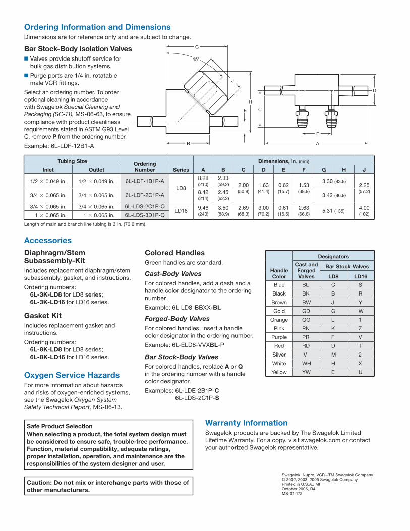
Ordering Information and DimensionsDimensions, in inches (millimeters), are for reference only and are subject to change.
Bar Stock-Body Distribution Valves■ Valves eliminate need for tee and cross fittings.
■ Branches contain shutoff valves.
■ Main line and branches are in same plane.
■ Purge ports are 1/4 in. rotatable male VCR fittings.
Select an ordering number. To order optional cleaning in accordance with Swagelok Special Cleaning and Packaging (SC-11), MS-06-63, to ensure compliance with product cleanliness requirements stated in ASTM G93 Level C, remove P from the ordering number.
Example: 6L-LDE-2B1-A
Double Horizontal TeeTerminates main line in body.
Nupro ELD 8 Sel Guide MS-02-20 N-ELD-482A schematic Double Horizontal Tee
3.42 (86.9)
2.25 (57.2)
90°
5.34 (136)
3.29 (83.6)
0.62 (15.7)
3.79 (96.3)
2.00 (50.8)
2.63 (66.8)
9.38 (238)
1.63 (41.4)
Branch
Branch
Main
Length of main and branch line tubing is 3 in. (76.2 mm).
0.76 (19.3)
1.35 (34.3)
1.98 (50.3)
2.45 (62.2)
Protective cap
Rotatable male VCR fittingForged-Body Valves with Purge PortsReplace X with M for 1/4 in. rotatable male VCR fitting purge ports.
Example: 6L-ELD8-11M-P
Forged-Body ValvesSelect an ordering number. To order optional cleaning in accordance with Swagelok Special Cleaning and Packaging (SC-11), MS-06-63, to ensure compliance with product cleanliness requirements stated in ASTM G93 Level C, remove -P from the ordering number.
Example: 6L-ELD8-VVX
End Connections Ordering Number
A in. (mm)Type Size
Tube butt weld
3/8 0.049 in. 6L-ELD8-VVX-P 2.88 (73.2)
1/2 0.049 in. 6L-ELD8-WWX-P
Tube extension, 3 in. (76.2 mm)
long
3/8 0.049 in. 6L-ELD8-33X-P 8.86 (225)
1/2 0.049 in. 6L-ELD8-11X-P
Rotatable male VCR fitting 1/2 in. 6L-ELD8-66X-P 5.43 (138)
Female VCR fitting 1/2 in. 6L-ELD8-77X-P 4.09 (104)
Tubing Size
Series Ordering NumberMain Branch
3/4 0.065 in. 1/2 0.049 in.
LD8 6L-LDE-2B1P-A
1/2 in. rotatable male VCR fitting 6L-LDE-2H1P-A

LD Series Diaphragm Valves 7
Double Horizontal CrossDirects main line flow through body.
Single Horizontal CrossDirects main line flow through body.
3.42 (86.9)
2.25 (57.2)
90°
5.34 (136)
3.29 (83.6)
0.62 (15.7)
2.00 (50.8)
2.63 (66.8)
9.38 (238)
1.63 (41.4)
7.58 (193)
2.33 (59.2)
2.25 (57.2)
45°
3.29 (83.6)
3.29 (83.6)
0.62 (15.7)
1.63 (41.4)
1.31 (33.3) 4.69
(119)
2.00 (50.8)
7.58 (193)
Length of main and branch line tubing is 3 in. (76.2 mm).
Length of main and branch line tubing is 3 in. (76.2 mm).
Main
Branch
Main
Branch
Branch
Main
Main
Tubing Size
Series Ordering NumberMain Branch
1/2 0.049 in.
1/4 0.035 in.
LD8
6L-LDA-1A1P-A
1/2 0.049 in. 6L-LDA-1B1P-A
1/4 in. rotatable male VCR fitting 6L-LDA-1L1P-A
1/2 in. rotatable male VCR fitting 6L-LDA-1H1P-A
3/4 0.065 in. 1/2 0.049 in. 6L-LDA-2B1P-A
1/2 in. rotatable male VCR fitting 6L-LDA-2H1P-A
1 0.065 in. 1/2 0.049 in. 6L-LDA-3B1P-A
1/2 in. rotatable male VCR fitting 6L-LDA-3H1P-A
Tubing Size
Series Ordering NumberMain Branch
1/2 0.049 in. 1/2 0.049 in.
LD8
6L-LDC-1B1P-A
1/2 in. rotatable male VCR fitting 6L-LDC-1H1P-A
3/4 0.065 in. 1/2 0.049 in. 6L-LDC-2B1P-A
1/2 in. rotatable male VCR fitting 6L-LDC-2H1P-A
1 0.065 in. 1/2 0.049 in. 6L-LDC-3B1P-A
1/2 in. rotatable male VCR fitting 6L-LDC-3H1P-A
Safe Product SelectionWhen selecting a product, the total system design must be considered to ensure safe, trouble-free performance. Function, material compatibility, adequate ratings, proper installation, operation, and maintenance are the responsibilities of the system designer and user.
Caution: Do not mix or interchange parts with those of other manufacturers.
Warranty InformationSwagelok products are backed by The Swagelok Limited Lifetime Warranty. For a copy, visit swagelok.com or contact your authorized Swagelok representative.
Swagelok, Nupro, VCR—TM Swagelok Company© 2002, 2003, 2005 Swagelok CompanyPrinted in U.S.A., MIOctober 2005, R4MS-01-172
Accessories
Diaphragm/Stem Subassembly-KitIncludes replacement diaphragm/stem subassembly, gasket, and instructions.
Ordering numbers: 6L-3K-LD8 for LD8 series; 6L-3K-LD16 for LD16 series.
Gasket KitIncludes replacement gasket and instructions.
Ordering numbers: 6L-8K-LD8 for LD8 series; 6L-8K-LD16 for LD16 series.
Colored HandlesGreen handles are standard.
Cast-Body ValvesFor colored handles, add a dash and a handle color designator to the ordering number.
Example: 6L-LD8-BBXX-BL
Forged-Body ValvesFor colored handles, insert a handle color designator in the ordering number.
Example: 6L-ELD8-VVXBL-P
Bar Stock-Body ValvesFor colored handles, replace A or Q in the ordering number with a handle color designator.
Examples: 6L-LDE-2B1P-C 6L-LDS-2C1P-S
A
C
D
F
B
E
J
G
H
45°
Length of main and branch line tubing is 3 in. (76.2 mm).
Bar Stock-Body Isolation Valves■ Valves provide shutoff service for
bulk gas distribution systems.
■ Purge ports are 1/4 in. rotatable male VCR fittings.
Select an ordering number. To order optional cleaning in accordance with Swagelok Special Cleaning and Packaging (SC-11), MS-06-63, to ensure compliance with product cleanliness requirements stated in ASTM G93 Level C, remove P from the ordering number.
Example: 6L-LDF-12B1-A
Oxygen Service HazardsFor more information about hazards and risks of oxygen-enriched systems, see the Swagelok Oxygen System Safety Technical Report, MS-06-13.
Tubing Size Ordering Number Series
Dimensions, in. (mm)
Inlet Outlet A B C D E F G H J
1/2 0.049 in. 1/2 0.049 in. 6L-LDF-1B1P-A LD8
8.28 (210)
2.33 (59.2) 2.00
(50.8) 1.63 (41.4)
0.62 (15.7)
1.53 (38.9)
3.30 (83.8) 2.25 (57.2)
3/4 0.065 in. 3/4 0.065 in. 6L-LDF-2C1P-A 8.42 (214)
2.45 (62.2) 3.42 (86.9)
3/4 0.065 in. 3/4 0.065 in. 6L-LDS-2C1P-Q LD16 9.46
(240) 3.50 (88.9)
2.69 (68.3)
3.00 (76.2)
0.61 (15.5)
2.63 (66.8) 5.31 (135) 4.00
(102)1 0.065 in. 1 0.065 in. 6L-LDS-3D1P-Q
Handle Color
Designators
Cast and Forged Valves
Bar Stock Valves
LD8 LD16
Blue BL C S
Black BK B R
Brown BW J Y
Gold GD G W
Orange OG L 1
Pink PN K Z
Purple PR F V
Red RD D T
Silver IV M 2
White WH H X
Yellow YW E U
Ordering Information and DimensionsDimensions are for reference only and are subject to change.