Diaphragm Valves - ASCO | Home - Fluid Automation. … · Aseptic valves ASCO diaphragm valves have...
10
Diaphragm Valves ASEPTIC APPLICATIONS
Transcript of Diaphragm Valves - ASCO | Home - Fluid Automation. … · Aseptic valves ASCO diaphragm valves have...

Diaphragm Valves
ASEPTIC APPLICATIONS

USPClass VI
An innovative design for demanding applications
ASCO diaphragm valves are technologically advanced and meet the most rigorous standards, enabling them to be applied to the most severe aseptic processes.
ASCO Numatics
Circumferential seat profi le
Elimination of microscopic areas where fl uid can be retained: Increased effectiveness of internal cleaning (EHEDG approved), reduction of the duration of SIP cleaning and the consumption,of washing solutions duringCIP.
Flexible diaphragm suspension
This new technology eliminates point loading at the centre of the diaphragm, enabling a longer service life. All diaphragm materials of the same size are interchangeable meaning there is no need to change the spindle or the compression plate.
Flexible diaphragm suspension
Compressor
Fabric inlay
Diaphragm with fabric inlay, threaded stud embedded in the diaphragm
Conventional seat
Conventional attachment
X
X
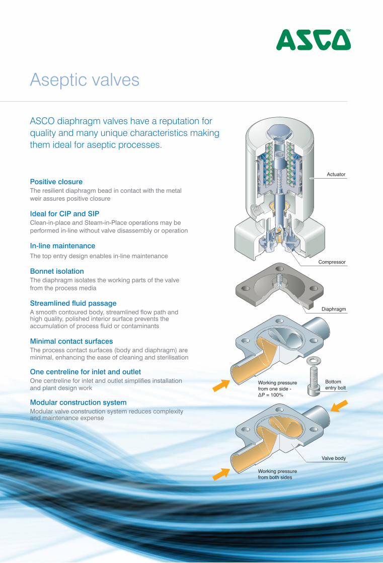
Aseptic valves
ASCO diaphragm valves have a reputation for quality and many unique characteristics making them ideal for aseptic processes.
Flexible diaphragm suspension
Compressor
Fabric inlay
Diaphragm with fabric inlay, threaded stud embedded in the diaphragm
Actuator
Compressor
Diaphragm
Working pressurefrom one side -ΔP = 100%
Working pressurefrom both sides
Bottomentry bolt
Valve body
Positive closureThe resilient diaphragm bead in contact with the metal weir assures positive closure
Ideal for CIP and SIPClean-in-place and Steam-in-Place operations may be performed in-line without valve disassembly or operation
In-line maintenanceThe top entry design enables in-line maintenance
Bonnet isolationThe diaphragm isolates the working parts of the valve from the process media
Streamlined fluid passageA smooth contoured body, streamlined flow path and high quality, polished interior surface prevents the accumulation of process fluid or contaminants
Minimal contact surfaces The process contact surfaces (body and diaphragm) are minimal, enhancing the ease of cleaning and sterilisation
One centreline for inlet and outletOne centreline for inlet and outlet simplifies installation and plant design work
Modular construction systemModular valve construction system reduces complexity and maintenance expense
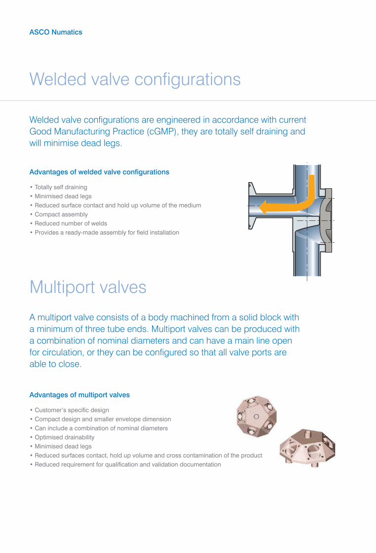
Welded valve configurations
ASCO Numatics
Welded valve configurations are engineered in accordance with current Good Manufacturing Practice (cGMP), they are totally self draining and will minimise dead legs.
A multiport valve consists of a body machined from a solid block with a minimum of three tube ends. Multiport valves can be produced with a combination of nominal diameters and can have a main line open for circulation, or they can be configured so that all valve ports are able to close.
Advantages of welded valve configurations
• Totally self draining• Minimised dead legs• Reduced surface contact and hold up volume of the medium• Compact assembly• Reduced number of welds• Provides a ready-made assembly for field installation
Multiport valves
Advantages of multiport valves
• Customer’s specific design• Compact design and smaller envelope dimension• Can include a combination of nominal diameters • Optimised drainability • Minimised dead legs• Reduced surfaces contact, hold up volume and cross contamination of the product • Reduced requirement for qualification and validation documentation

Tank valves
The sampling unit is suitable to take sterile samples from all liquids in aseptic processes i.e. high purity water, high purity steam, fermentation processes, parenteral drugs etc. Samples can be taken in a continuous process with pneumatic controlled diaphragm valves or typically as a system with manual valves.
Process solutions
Sampling bottle with pneumatic actuated valves
The ASCO tank bottom valve is designed for applications in the aseptic process industry offering a pocket-free interior surface, minimised sump, eliminating entrapment areas and minimizing fl ow resistance thus reducing the potential for process contamination.
Tank
Crankshaftextended stem
Easy access to themanual bonnet handle
Tank bottom body
Tank
Side mounted bodymanufactured accordingto the tank diameter radius
Pneumaticallyoperated tankbottom valveSteripur Series
Sampling bottle with pneumatic actuated valves
KM
D
DN 100
DN 80
DN 80
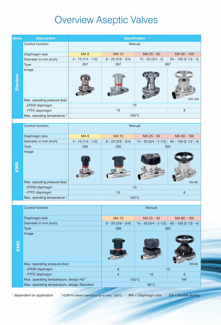
Overview Aseptic Valves
1 dependent on application 2 KDM for steam sterilizing up to max. 150°C MA = Diaphragm size DA = Double Acting
Ste
rip
ur
Ste
rip
ur
NC NC, NO, DA
MA 8 MA 10 MA 25 - 50 MA 80 - 100 MA 8 MA 10 MA 25 - 50 MA 80 - 100
4 - 15 (1/4 - 1/2) 8 - 20 (3/8 - 3/4) 15 - 50 (3/4 - 2) 65 - 100 (2 1/2 - 4) 4 - 15 (1/4 - 1/2) 8 - 20 (3/8 - 3/4) 15 - 50 (3/4 - 2 1/2) 65 - 100 (2 1/2 - 4)
297 397 997 207.30 207.25 307 407 407
10 8 4,5 8 10 7 - 6
10 8 7 4 7 8 6 - 5
160°C 160°C
KM
A
KM
A
MA 8 MA 10 MA 25 - 50 MA 80 - 100 MA 8 MA 10 MA 25 - 50 MA 80 - 100
4 - 15 (1/4 - 1/2) 8 - 20 (3/8 - 3/4) 15 - 50 (3/4 - 2 1/2) 65 - 100 (2 1/2 - 4) 4 - 15 (1/4 - 1/2) 8 - 20 (3/8 - 3/4) 15 - 50 (3/4 - 2 1/2) 65 - 100 (2 1/2 - 4)
290 295 995 190 195 495
10 8 10 7 - 6
10 8 7 8 6 - 5
160°C 160°C
NC, NO, DA
MA 10 MA 25 - 50 MA 80 - 100 MA 10 MA 25 - 50 MA 25 - 80
8 - 20 (3/8 - 3/4) 15 - 50 (3/4 - 2 1/2) 65 - 100 (2 1/2 - 4) 8 - 20 (3/8 - 3/4) 15 - 50 (3/4 - 2 1/2) 15 - 80 (3/4 - 3)
289 985 188 402 385
6 10 8 10 10 - 7
6 10 8 7 8 8 - 6
150°C 150°C
80°C 80°C
Series Description Specifi cation Specifi cation Series
Control function Manual Pneumatically operated
Diaphragm size
Diameter in mm (inch)
Type
Image
Max. operating pressure (bar)
- EPDM diaphragm
- PTFE diaphragm
Max. operating temperature 1
Control function Manual Pneumatically operated
Diaphragm size
Diameter in mm (inch)
Type
Image
Max. operating pressure (bar)
- EPDM diaphragm
- PTFE diaphragm
Max. operating temperature 1
Control function Manual Pneumatically operated
Diaphragm size
Diameter in mm (inch)
Type
Image
Max. operating pressure (bar)
- EPDM diaphragm
- PTFE diaphragm
Max. operating temperature, design HS 2 NA NA
Max. operating temperature, design Standard

KM
D
Ste
rip
ur
Ste
rip
ur
NC NC, NO, DA
MA 8 MA 10 MA 25 - 50 MA 80 - 100 MA 8 MA 10 MA 25 - 50 MA 80 - 100
4 - 15 (1/4 - 1/2) 8 - 20 (3/8 - 3/4) 15 - 50 (3/4 - 2) 65 - 100 (2 1/2 - 4) 4 - 15 (1/4 - 1/2) 8 - 20 (3/8 - 3/4) 15 - 50 (3/4 - 2 1/2) 65 - 100 (2 1/2 - 4)
297 397 997 207.30 207.25 307 407 407
10 8 4,5 8 10 7 - 6
10 8 7 4 7 8 6 - 5
160°C 160°C
KM
A
KM
A
MA 8 MA 10 MA 25 - 50 MA 80 - 100 MA 8 MA 10 MA 25 - 50 MA 80 - 100
4 - 15 (1/4 - 1/2) 8 - 20 (3/8 - 3/4) 15 - 50 (3/4 - 2 1/2) 65 - 100 (2 1/2 - 4) 4 - 15 (1/4 - 1/2) 8 - 20 (3/8 - 3/4) 15 - 50 (3/4 - 2 1/2) 65 - 100 (2 1/2 - 4)
290 295 995 190 195 495
10 8 10 7 - 6
10 8 7 8 6 - 5
160°C 160°C
NC, NO, DA
MA 10 MA 25 - 50 MA 80 - 100 MA 10 MA 25 - 50 MA 25 - 80
8 - 20 (3/8 - 3/4) 15 - 50 (3/4 - 2 1/2) 65 - 100 (2 1/2 - 4) 8 - 20 (3/8 - 3/4) 15 - 50 (3/4 - 2 1/2) 15 - 80 (3/4 - 3)
289 985 188 402 385
6 10 8 10 10 - 7
6 10 8 7 8 8 - 6
150°C 150°C
80°C 80°C
Overview Aseptic Valves
Series Description Specifi cation Specifi cation Series
Control function Manual Pneumatically operated
Diaphragm size
Diameter in mm (inch)
Type
Image
Max. operating pressure (bar)
- EPDM diaphragm
- PTFE diaphragm
Max. operating temperature 1
Control function Manual Pneumatically operated
Diaphragm size
Diameter in mm (inch)
Type
Image
Max. operating pressure (bar)
- EPDM diaphragm
- PTFE diaphragm
Max. operating temperature 1
Control function Manual Pneumatically operated
Diaphragm size
Diameter in mm (inch)
Type
Image
Max. operating pressure (bar)
- EPDM diaphragm
- PTFE diaphragm
Max. operating temperature, design HS 2 NA NA
Max. operating temperature, design Standard
sød
LL1
h 1/h
2
ISO 1127 DIN 11850 DIN ASTM 269 BS O.D. SMS JIS G
ASME BPE 4825 3008 3447
Code 40 41 42 39 45* 94 49 97
DN NPS MA L(min) L1 h1 h2 Ød x s ød x s ød x s ød x s ød s s ød x s ød x s
4 - 8 20 72 9 9 - - - 6x1,0 - - - -
6 - 8 20 72 9 9 - - - 8x1,0 - - - -
8 1/4 8 20 72 9 9 13,5x1,6 - - 10x1,0 6,35 0,89 - -
10 3/8 8 20 72 9 9 - 12x1,0 13x1,5 - 9,53 0,89 - -
15 1/2 8 20 72 9 9 - - - - 12,7 1,65 1,2 - -
8 - 10 25 108 12 12 13,5x1,6 - - - - - - -
10 3/8 10 25 108 12 12 17,2x1,6 12x1,0 13x1,5 - 9,53 0,89 - -
15 1/2 10 25 108 12 12 21,3x1,6 18x1,0 19x1,5 18x1,5 12,7 1,65 1,2 - -
20 3/4 10 25 108 12 12 - - 23x1,5 22x1,5 19,05 1,65 1,2 - -
15 - 25 25 120 13 16 21,3x1,6 18x1,0 19x1,5 - - - - -
20 3/4 25 25 120 16 16 26,9x1,6 22x1,0 23x1,5 - 19,05 1,65 - -
25 1 25 25 120 19 19 33,7x2,0 28x1,0 29x1,5 - 25,4 1,65 25,0x1,2 25,4x1,2
32 1 1/4 40 25 153 24 26 42,4x2,0 34x1,0 35x1,5 - 31,75 1,65 33,7x1,2 31,8x1,2
40 1 1/2 40 25 153 24 26 48,3x2,0 40x1,0 41x1,5 - 38,1 1,65 38,0x1,2 38,1x1,2
50 2 50 30 173 32 32 60,3x2,0 52x1,0 53x1,5 - 50,8 1,65 51,0x1,2 50,8x1,5
65 2 1/2 50 30 173 32 32 - - - - 63,5 1,65 63,5x1,6
65 2 1/2 80 25 216 47 47 76,1x2,0 - 70x2,0 - 63,5 1,65 63,5x1,6
80 3 80 30 254 47 47 88,9x2,3 - 85x2,0 - 76,2 1,65 76,1x1,6 76,3x2,0
100 4 100 30 305 61 58 114,3x2,3 - 104x2,0 - 101,6 2,11 101,6x2,0 101,6x2,1
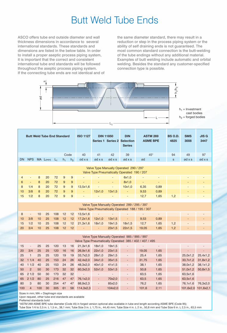
Butt Weld Tube Ends
Sizes in mm; MA = Diaphragm size Upon request, other tube end standards are available Preferred standards bold *ASTM 269 ASME BPE tube diameter (Code 45) in forged version optional also available in tube end length according ASME BPE (Code 95); Tube Size 1/4 to 2,5 in. L 1,5 in., 38,1 mm; Tube Size 3 in. L 1,75 in., 44,45 mm; Tube Size 4 in. L 2 in., 50,8 mm and Tube Size 6 in. L 2,5 in., 63,5 mm
Butt Weld Tube End Standard
Series 1
Valve Type Manually Operated 290 / 297Valve Type Pneumatically Operated 190 / 207
Valve Type Manually Operated 289 / 295 / 397Valve Type Pneumatically Operated 188 / 195 / 307
Valve Type Manually Operated 985 / 995 / 997Valve Type Pneumatically Operated 385 / 402 / 407 / 495
Series 2 Selection
Series
h1 = Investment cast bodiesh2 = forged bodies
ASCO offers tube end outside diameter and wall thickness dimensions in accordance to several international standards. These standards and dimensions are listed in the below table. In order to install a proper aseptic process piping system,it is important that the correct and consistent international tube end standards will be followed throughout the aseptic process piping system. If the connecting tube ends are not identical and of
the same diameter standard, there may result in a reduction or step in the process piping system or the ability of self draining ends is not guaranteed. The most common standard connection is the butt-welding of the tube endings without any additional material. Examples of butt welding include automatic and orbital welding. Besides the standard any customer-specified connection type is possible.
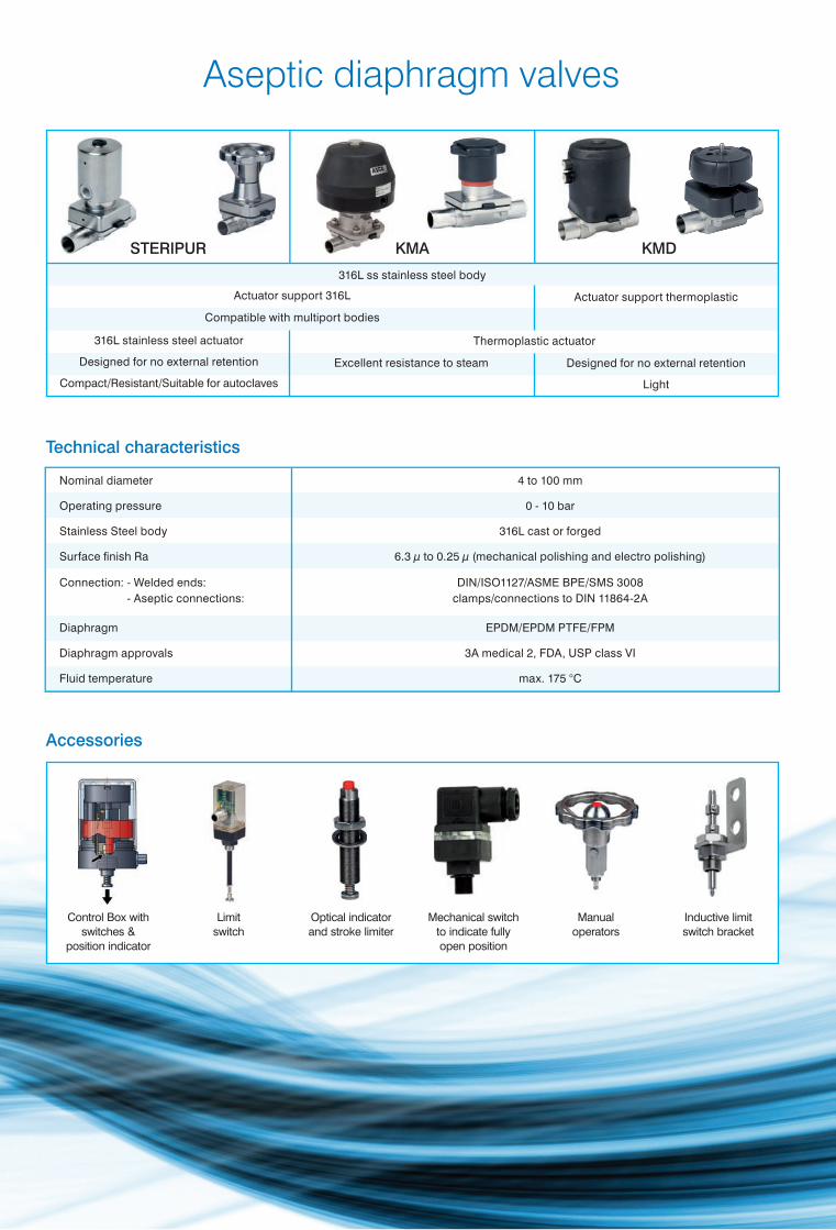
Nominal diameter 4 to 100 mm
Operating pressure 0 - 10 bar
Stainless Steel body 316L cast or forged
Surface fi nish Ra 6.3 µ to 0.25 µ (mechanical polishing and electro polishing)
Connection: - Welded ends: DIN/ISO1127/ASME BPE/SMS 3008- Aseptic connections: clamps/connections to DIN 11864-2A
Diaphragm EPDM/EPDM PTFE/FPM
Diaphragm approvals 3A medical 2, FDA, USP class VI
Fluid temperature max. 175 °C
Control Box with switches &
position indicator
Limitswitch
Optical indicator and stroke limiter
Mechanical switch to indicate fully open position
Manual operators
Inductive limit switch bracket
316L stainless steel actuator
Designed for no external retention
Compact/Resistant/Suitable for autoclaves
Excellent resistance to steam
316L ss stainless steel body
Actuator support 316L
Compatible with multiport bodies
Thermoplastic actuator
Actuator support thermoplastic
Designed for no external retention
Light
KMDSTERIPUR KMA
Aseptic diaphragm valves
Technical characteristics
Accessories