Diagnostic Trouble Code (DTC) Guide for Omnitek …en.tedomengines.com/down/345.pdf · Diagnostic...
226
Diagnostic Trouble Code (DTC) Guide for Omnitek ECM 64A/66A/88A TEDOM a.s., Engines Division, Belgická 4685/15, 466 05 Jablonec nad Nisou, Czech Republic Tel. +420 483 363 326 - www.tedomengines.com
Transcript of Diagnostic Trouble Code (DTC) Guide for Omnitek …en.tedomengines.com/down/345.pdf · Diagnostic...
Diagnostic Trouble Code (DTC) Guide
for Omnitek ECM 64A/66A/88A
TEDOM a.s., Engines Division, Belgická 4685/15, 466 05 Jablonec nad Nisou, Czech Republic
Tel. +420 483 363 326 - www.tedomengines.com


Comments, questions or reporting of any errors found regarding this document are welcome and appreciated. Please direct them to:
TEDOM a.s., Engines Division
Belgická 4685/15
466 05 Jablonec nad Nisou, Czech Republic
Tel.: +420 483 363 326
www.tedomengines.com
TABLE OF CONTENTS
TABLE OF CONTENTS ........................................................................................................................................................ II
1 INTRODUCTION ........................................................................................................................................................ 1
2 DTC TYPE DEFINITION ............................................................................................................................................ 2
2.1 Trip Logic ........................................................................................................................................................ 2
2.2 DTC Type A1 .................................................................................................................................................. 3
2.3 DTC Type A2 .................................................................................................................................................. 3
2.4 DTC Type B .................................................................................................................................................... 3
2.5 DTC Type B3 .................................................................................................................................................. 3
2.6 DTC Type C1 .................................................................................................................................................. 4
2.7 DTC Type C2 .................................................................................................................................................. 4
2.8 DTC Type C3 .................................................................................................................................................. 4
2.9 DTC Type X .................................................................................................................................................... 4
2.10 DTC Type Y .................................................................................................................................................. 4
2.11 DTC Status Update Logic ............................................................................................................................. 5
2.11.1 DTC Conditions Met ............................................................................................................................ 5
2.11.2 Trip Conditions Met ............................................................................................................................. 5
2.11.3 ECM Key-Off / Powerdown Sequence ............................................................................................... 5
2.12 Snapshot Logic ............................................................................................................................................. 6
2.13 Malfunction Indicator Lamp Logic................................................................................................................. 6
2.14 End Of Line / Repaired Vehicle DTC Check ................................................................................................ 7
3 DIAGNOSTIC TROUBLE CODE GUIDE ........................................................................................................................ 8
3.1 DTC P0006 Fuel Shutoff A Solenoid Circuit Low ........................................................................................ 8
3.2 DTC P0007 Fuel Shutoff A Solenoid Circuit High ....................................................................................... 8
3.3 DTC P0031 Oxygen Sensor 1, Bank 1, Heater Low ................................................................................... 9
3.4 DTC P0032 Oxygen Sensor 1, Bank 1, Heater High ................................................................................ 10
3.5 DTC P0037 Oxygen Sensor 2, Bank 1, Heater Low ................................................................................. 11
3.6 DTC P0038 Oxygen Sensor 2, Bank 1, Heater High ................................................................................ 12
3.7 DTC P0051 Oxygen Sensor 1, Bank 2, Heater Low ................................................................................. 12
3.8 DTC P0052 Oxygen Sensor 1, Bank 2, Heater High ................................................................................... 13
3.9 DTC P0057 Oxygen Sensor 2, Bank 2, Heater Low.................................................................................... 14
3.10 DTC P0058 Oxygen Sensor 2, Bank 2, Heater High ................................................................................. 15
3.11 DTC P0068 MAP/MAF/Throttle Position Correlation ................................................................................. 15
3.12 DTC P0087 Fuel Rail/System Pressure Too Low ..................................................................................... 16
3.13 DTC P0088 Fuel Rail/System Pressure Too High ..................................................................................... 17
3.14 DTC P0093 Large Fuel Rail Leak .............................................................................................................. 18
3.15 DTC P0094 Small Fuel Rail Leak .............................................................................................................. 19
3.16 DTC P0102 Mass Air Flow Sensor Low .................................................................................................... 20
3.17 DTC P0103 Mass Air Flow Sensor High ................................................................................................... 21
3.18 DTC P0107 Manifold Absolute Pressure Sensor Low ............................................................................... 22
3.19 DTC P0108 Manifold Absolute Pressure Sensor High .............................................................................. 23
3.20 DTC P0112 Intake Air Temperature Sensor Low ...................................................................................... 24
3.21 DTC P0113 Intake Air Temperature Sensor High ..................................................................................... 25
3.22 DTC P0117 Engine Coolant Temperature Sensor Low............................................................................. 25
3.23 DTC P0118 Engine Coolant Temperature Sensor High ............................................................................ 26
3.24 DTC P0122 Throttle Position Sensor Low ................................................................................................. 27
3.25 DTC P0123 Throttle Position Sensor High ................................................................................................ 28
3.26 DTC P0125 Insufficient Coolant Temperature for Closed-Loop ................................................................ 29
3.27 DTC P0126 Insufficient Coolant Temperature for Stable Operation ......................................................... 30
3.28 DTC P0127 Intake Air Temperature Too High .......................................................................................... 31
3.29 DTC P0128 Thermostat Performance ....................................................................................................... 32
3.30 DTC P0129 Barometric Pressure Too Low ............................................................................................... 33
3.31 DTC P0131 Oxygen Sensor 1, Bank 1, Voltage Low ................................................................................ 33
3.32 DTC P0132 Oxygen Sensor 1, Bank 1, Voltage High ............................................................................... 34
3.33 DTC P0133 Oxygen Sensor 1, Bank 1, Sluggish ...................................................................................... 35
3.34 DTC P0134 Oxygen Sensor 1, Bank 1, Inactivity ...................................................................................... 36
3.35 DTC P0137 Oxygen Sensor 2, Bank 1 Voltage Low ................................................................................. 37
3.36 DTC P0138 Oxygen Sensor 2, Bank 1, Voltage High ............................................................................... 37
3.37 DTC P0139 Oxygen Sensor 2, Bank 1, Slow response ............................................................................ 38
3.38 DTC P0140 Oxygen Sensor 2, Bank 1, Inactivity ...................................................................................... 39
3.39 DTC P0182 Fuel Temperature Sensor Low .............................................................................................. 40
3.40 DTC P0183 Fuel Temperature Sensor High ............................................................................................. 41
3.41 DTC P0192 Fuel Rail Pressure Sensor Low .......................................................................................... 42
3.42 DTC P0193 Fuel Rail Pressure Sensor High ......................................................................................... 42
3.43 DTC P0217 Engine Overheat ................................................................................................................. 43
3.44 DTC P0219 Engine Over Speed ............................................................................................................. 44
3.45 DTC P0222 Throttle Position Sensor B Low .......................................................................................... 44
3.46 DTC P0223 Throttle Position Sensor B High.......................................................................................... 45
3.47 DTC P0234 Engine Over Boost Condition ............................................................................................. 46
3.48 DTC P0236 Boost Pressure Sensor Performance ................................................................................. 47
3.49 DTC P0237 Boost Pressure Sensor Low ............................................................................................... 48
3.50 DTC P0238 Boost Pressure Sensor High .............................................................................................. 49
3.51 DTC P0245 Turbocharger Wastegate Solenoid Circuit Low .................................................................. 50
3.52 DTC P0246 Turbocharger Wastegate Solenoid Circuit High ................................................................. 51
3.53 DTC P0261 Injector 1 Circuit Low .......................................................................................................... 52
3.54 DTC P0262 Injector 1 Circuit High .......................................................................................................... 53
3.55 DTC P0263 Injector 1 Contribution/Balance........................................................................................... 54
3.56 DTC P0264 Injector 2 Circuit Low .......................................................................................................... 54
3.57 DTC P0265 Injector 2 Circuit High .......................................................................................................... 55
3.58 DTC P0266 Injector 2 Contribution/Balance........................................................................................... 56
3.59 DTC P0267 Injector 3 Circuit Low .......................................................................................................... 57
3.60 DTC P0268 Injector 3 Circuit High .......................................................................................................... 58
3.61 DTC P0269 Injector 3 Contribution/Balance........................................................................................... 59
3.62 DTC P0270 Injector 4 Circuit Low .......................................................................................................... 60
3.63 DTC P0271 Injector 4 Circuit High .......................................................................................................... 61
3.64 DTC P0272 Injector 4 Contribution/Balance........................................................................................... 62
3.65 DTC P0273 Injector 5 Circuit Low .......................................................................................................... 63
3.66 DTC P0274 Injector 5 Circuit High .......................................................................................................... 64
3.67 DTC P0275 Injector 5 Contribution/Balance........................................................................................... 65
3.68 DTC P0276 Injector 6 Circuit Low .......................................................................................................... 65
3.69 DTC P0277 Injector 6 Circuit High .......................................................................................................... 66
3.70 DTC P0278 Injector 6 Contribution/Balance........................................................................................... 67
3.71 DTC P0279 Injector 7 Circuit Low .......................................................................................................... 68
3.72 DTC P0280 Injector 7 Circuit High .......................................................................................................... 69
3.73 DTC P0281 Injector 7 Contribution/Balance........................................................................................... 70
3.74 DTC P0282 Injector 8 Circuit Low ............................................................................................................. 71
3.75 DTC P0283 Injector 8 Circuit High ............................................................................................................. 72
3.76 DTC P0284 Injector 8 Contribution/Balance.............................................................................................. 73
3.77 DTC P0297 Vehicle Over Speed ............................................................................................................... 74
3.78 DTC P0300 Random Misfire ...................................................................................................................... 74
3.79 DTC P0301 Misfire, Cylinder 1 .................................................................................................................. 76
3.80 DTC P0302 Misfire, Cylinder 2 .................................................................................................................. 77
3.81 DTC P0303 Misfire, Cylinder 3 .................................................................................................................. 79
3.82 DTC P0304 Misfire, Cylinder 4 .................................................................................................................. 80
3.83 DTC P0305 Misfire, Cylinder 5 .................................................................................................................. 81
3.84 DTC P0306 Misfire, Cylinder 6 .................................................................................................................. 83
3.85 DTC P0307 Misfire, Cylinder 7 .................................................................................................................. 84
3.86 DTC P0308 Misfire, Cylinder 8 .................................................................................................................. 86
3.87 DTC P0313 Misfire Detected with Low Fuel .............................................................................................. 87
3.88 DTC P0327 Knock Sensor 1 Low .............................................................................................................. 88
3.89 DTC P0328 Knock Sensor 1 High ............................................................................................................. 89
3.90 DTC P0332 Knock Sensor 2 Low .............................................................................................................. 90
3.91 DTC P0333 Knock Sensor 2 High ............................................................................................................. 91
3.92 DTC P0335 Crankshaft Position Sensor Circuit Fault ............................................................................... 92
3.93 DTC P0340 Camshaft Position Sensor Fault ............................................................................................ 93
3.94 DTC P0420 Catalyst System Low Efficiency ............................................................................................. 94
3.95 DTC P0462 Fuel Quantity Sensor Low ..................................................................................................... 94
3.96 DTC P0463 Fuel Quantity Sensor High ..................................................................................................... 95
3.97 DTC P0502 Vehicle Speed Sensor Low .................................................................................................... 96
3.98 DTC P0503 Vehicle Speed Sensor High or Erratic ................................................................................... 97
3.99 DTC P0506 Idle Control System RPM Too Low ....................................................................................... 98
3.100 DTC P0507 Idle Control System RPM Too High ..................................................................................... 99
3.101 DTC P0508 Idle Air Control Circuit Low ................................................................................................ 100
3.102 DTC P0509 Idle Speed Control Circuit High ......................................................................................... 101
3.103 DTC P0522 Engine Oil Pressure Sensor Low ....................................................................................... 101
3.104 DTC P0523 Engine Oil Pressure Sensor High ...................................................................................... 102
3.105 DTC P0524 Engine Oil Pressure Low ................................................................................................... 103
3.106 DTC P0530 Air Conditioning Pressure Sensor Circuit Error ................................................................. 103
3.107 DTC P0534 Air Conditioning Refrigerant Loss .................................................................................... 104
3.108 DTC P0545 Exhaust Temperature Sensor Low .................................................................................. 105
3.109 DTC P0546 Exhaust Temperature Sensor High ................................................................................. 105
3.110 DTC P0561 System Voltage Unstable ................................................................................................ 106
3.111 DTC P0562 System Voltage Low ........................................................................................................ 107
3.112 DTC P0563 System Voltage High ....................................................................................................... 107
3.113 DTC P0603 Keep-Alive Memory Fault ................................................................................................ 108
3.114 DTC P0604 RAM Fault ....................................................................................................................... 108
3.115 DTC P0605 Flash/ROM Fault ............................................................................................................. 109
3.116 DTC P0606 ECM Fault ....................................................................................................................... 109
3.117 DTC P0615 Starter Control Relay Circuit ............................................................................................ 110
3.118 DTC P0622 Alternator Field Current Monitor Fault ............................................................................. 110
3.119 DTC P0636 Power Steering Control Relay Circuit Open .................................................................... 111
3.120 DTC P0637 Power Steering Control Relay Circuit Shorted ................................................................ 111
3.121 DTC P0638 Throttle Control Performance .......................................................................................... 112
3.122 DTC P0642 Sensor Reference Voltage A Low ................................................................................... 113
3.123 DTC P0643 Sensor Reference Voltage A High .................................................................................. 114
3.124 DTC P0646 A/C Control Relay Circuit Open ....................................................................................... 114
3.125 DTC P0647 A/C Control Relay Circuit Shorted ................................................................................... 115
3.126 DTC P0650 Malfunction Indicator Lamp Circuit Fault ......................................................................... 115
3.127 DTC P0652 Sensor Reference Voltage B Low ................................................................................... 116
3.128 DTC P0653 Sensor Reference Voltage B High .................................................................................. 117
3.129 DTC P0654 Engine Speed Output Circuit Fault .................................................................................. 117
3.130 DTC P0655 Overheat Lamp Circuit Fault ........................................................................................... 118
3.131 DTC P0656 Fuel Level Output Circuit Fault ........................................................................................ 118
3.132 DTC P0657 Actuator Power Control Relay Circuit Open .................................................................... 119
3.133 DTC P0658 Actuator Power Voltage Low ........................................................................................... 119
3.134 DTC P0659 Actuator Power Voltage High .......................................................................................... 120
3.135 DTC P0686 Power Control Relay Circuit Low..................................................................................... 121
3.136 DTC P0687 Power Control Relay Circuit High .................................................................................... 122
3.137 DTC P0691 Fan 1 Relay Control Circuit Low ...................................................................................... 122
3.138 DTC P0692 Fan 1 Relay Control Circuit High ..................................................................................... 123
3.139 DTC P0693 Fan 2 Relay Control Circuit Low ...................................................................................... 124
3.140 DTC P0694 Fan 2 Relay Control Circuit High ........................................................................................ 124
3.141 DTC P0695 Fan 3 Relay Control Circuit Low ......................................................................................... 125
3.142 DTC P0696 Fan 3 Relay Control Circuit High ........................................................................................ 126
3.143 DTC P0698 Sensor Reference Voltage C Low ...................................................................................... 126
3.144 DTC P0699 Sensor Reference Voltage C High ..................................................................................... 127
3.145 DTC P1134 Oxygen Sensor 1, Bank 1, Erratic Air-Fuel Ratio ............................................................... 128
3.146 DTC P1135 Oxygen Sensor 1, Bank 1, Oxygen Sensor Lean Shift ...................................................... 129
3.147 DTC P1136 Oxygen Sensor 1, Bank 1, Oxygen Sensor Rich Shift ....................................................... 130
3.148 DTC P1137 Oxygen Sensor 1, Bank 1, Oxygen Sensor High Impedance ............................................ 131
3.149 DTC P1138 Oxygen Sensor 1, Bank 1, Oxygen Sensor Overheat Condition ....................................... 132
3.150 DTC P1517 Backup TPS Data Does Not Match .................................................................................... 133
3.151 DTC P1518 Unable to complete throttle zero process ........................................................................... 134
3.152 DTC P1519 No Backup TPS Zero Data Found ..................................................................................... 135
3.153 DTC P1520 No Primary TPS Zero Data Found ..................................................................................... 135
3.154 DTC P1521 Throttle Resting Position Incorrect ..................................................................................... 136
3.155 DTC P1522 Throttle Resting Position Incorrect After Span ................................................................... 137
3.156 DTC P1524 Low Oil Pressure Lamp Circuit Fault .................................................................................. 138
3.157 DTC P1525 Customer-Specific Lamp Circuit A Fault ............................................................................ 138
3.158 DTC P1526 Customer-Specific Lamp Circuit B Fault ............................................................................ 139
3.159 DTC P1560 Low Coolant Level Lamp Circuit Fault................................................................................ 140
3.160 DTC P1609 Calibration/Firmware Mismatch .......................................................................................... 140
3.161 DTC P1630/P1631 Electronic Throttle Driver Overheat......................................................................... 141
3.162 DTC P1632 Electronic Throttle Driver Overheat Shutdown ................................................................... 141
3.163 DTC P1633 Electronic Throttle Driver Overvoltage Shutdown .............................................................. 142
3.164 DTC P1655 Coolant Temperature Output Circuit Fault ......................................................................... 143
3.165 DTC P1656 Low Fuel Lamp Circuit Fault ............................................................................................... 143
3.166 DTC P1657 Stop Engine Lamp Circuit Fault .......................................................................................... 144
3.167 DTC P1661 Internal Power Supply Voltage Low ................................................................................... 145
3.168 DTC P1662 Internal Power Supply Voltage High................................................................................... 145
3.169 DTC P1666 Fuel Shutoff C Solenoid Circuit Low ................................................................................... 145
3.170 DTC P1667 Fuel Shutoff C Solenoid Circuit High .................................................................................. 146
3.171 DTC P1690 Maintenance Reminder ...................................................................................................... 147
3.172 DTC P2096 Post Catalyst Fuel Trim System Too Lean ......................................................................... 147
3.173 DTC P2097 Post Catalyst Fuel Trim System Too Rich ...................................................................... 148
3.174 DTC P2100 Throttle Actuator Control Motor Circuit Open ................................................................. 150
3.175 DTC P2102 Throttle Actuator Control Motor Circuit Low .................................................................... 150
3.176 DTC P2103 Throttle Actuator Control Motor Circuit High ................................................................... 151
3.177 DTC P2111 Throttle Stuck Open ........................................................................................................ 152
3.178 DTC P2112 Throttle Stuck Closed ...................................................................................................... 153
3.179 DTC P2122 Accelerator Pedal Position Sensor D Low ...................................................................... 153
3.180 DTC P2123 Accelerator Pedal Position Sensor D High ..................................................................... 154
3.181 DTC P2127 Accelerator Pedal Position Sensor E Low ...................................................................... 155
3.182 DTC P2128 Accelerator Pedal Position Sensor E High ..................................................................... 156
3.183 DTC P2132 Accelerator Pedal Position Sensor F Low ...................................................................... 157
3.184 DTC P2133 Accelerator Pedal Position Sensor F High ...................................................................... 158
3.185 DTC P2135 Throttle Position Sensor A-B Correlation ........................................................................ 159
3.186 DTC P2138 Accelerator Pedal Position Sensor D-E Correlation ....................................................... 160
3.187 DTC P2139 Accelerator Pedal Position Sensor D-F Correlation ....................................................... 161
3.188 DTC P2139 Accelerator Pedal Position Sensor E-F Correlation ........................................................ 161
3.189 DTC P2172 Sudden High Airflow Detected ........................................................................................ 162
3.190 DTC P2173 High Airflow Detected ...................................................................................................... 163
3.191 DTC P2174 Sudden Low Airflow Detected ......................................................................................... 164
3.192 DTC P2175 Low Airflow Detected ...................................................................................................... 165
3.193 DTC P2176 Idle Position Not Learned ................................................................................................ 166
3.194 DTC P2177 Fuel System Too Lean off-Idle, Bank 1........................................................................... 167
3.195 DTC P2178 Fuel System Too Rich off-Idle, Bank 1 ........................................................................... 168
3.196 DTC P2187 Fuel System Too Lean at Idle, Bank 1 ............................................................................ 169
3.197 DTC P2188 Fuel System Too Rich at Idle, Bank 1............................................................................. 170
3.198 DTC P2191 Fuel System Too Lean At High Load, Bank 1 ................................................................. 171
3.199 DTC P2192 Fuel System Too Rich At High Load, Bank 1 ................................................................. 172
3.200 DTC P2195 Oxygen Sensor 1, Bank 1, Signal Stuck Lean ................................................................ 173
3.201 DTC P2196 Oxygen Sensor 1, Bank 1, Signal Stuck Rich ................................................................. 174
3.202 DTC P2231 Oxygen Sensor 1, Bank 1, Shorted to Heater ................................................................ 175
3.203 DTC P2243 Oxygen Sensor Reference Circuit, Bank 1, Sensor 1 .................................................... 176
3.204 DTC P2261 Turbocharger Bypass Valve - Mechanical ...................................................................... 176
3.205 DTC P2262 Turbocharger Boost Pressure - Mechanical ................................................................... 177
3.206 DTC P2263 Turbocharger Boost Pressure System Performance ..................................................... 178
3.207 DTC P2270 Oxygen Sensor 2, Bank 1, Signal Stuck Lean ............................................................... 179
3.208 DTC P2271 Oxygen Sensor 2, Bank 1, Signal Stuck Rich ................................................................ 180
3.209 DTC P2297 Oxygen Sensor 1, Bank 1, Signal Stuck Rich During Deceleration ............................... 181
3.210 DTC P2299 Accelerator Pedal Position Sensor and Brake Switch Incompatible .............................. 182
3.211 DTC P2300 Ignition Coil 1 Circuit Primary Low Current .................................................................... 183
3.212 DTC P2301 Ignition Coil 1 Circuit Primary High Current ................................................................... 184
3.213 DTC P2302 Ignition Coil 1 Circuit Secondary Fault ........................................................................... 184
3.214 DTC P2303 Ignition Coil 2 Circuit Primary Low Current .................................................................... 185
3.215 DTC P2304 Ignition Coil 2 Circuit Primary High Current ................................................................... 186
3.216 DTC P2305 Ignition Coil 2 Circuit Secondary Fault ........................................................................... 187
3.217 DTC P2306 Ignition Coil 3 Circuit Primary Low Current .................................................................... 188
3.218 DTC P2307 Ignition Coil 3 Circuit Primary High Current ................................................................... 188
3.219 DTC P2308 Ignition Coil 3 Circuit Secondary Fault ........................................................................... 189
3.220 DTC P2309 Ignition Coil 4 Circuit Primary Low Current .................................................................... 190
3.221 DTC P2310 Ignition Coil 4 Circuit Primary High Current ................................................................... 191
3.222 DTC P2311 Ignition Coil 4 Circuit Secondary Fault ........................................................................... 191
3.223 DTC P2312 Ignition Coil 5 Circuit Primary Low Current .................................................................... 192
3.224 DTC P2313 Ignition Coil 5 Circuit Primary High Current ................................................................... 193
3.225 DTC P2314 Ignition Coil 5 Circuit Secondary Fault ........................................................................... 194
3.226 DTC P2315 Ignition Coil 6 Circuit Primary Low Current .................................................................... 195
3.227 DTC P2316 Ignition Coil 6 Circuit Primary High Current ................................................................... 195
3.228 DTC P2317 Ignition Coil 6 Circuit Secondary Fault ........................................................................... 196
3.229 DTC P2318 Ignition Coil 7 Circuit Primary Low Current .................................................................... 197
3.230 DTC P2319 Ignition Coil 7 Circuit Primary High Current ................................................................... 198
3.231 DTC P2320 Ignition Coil 7 Circuit Secondary Fault ........................................................................... 198
3.232 DTC P2321 Ignition Coil 8 Circuit Primary Low Current .................................................................... 199
3.233 DTC P2322 Ignition Coil 8 Circuit Primary High Current ................................................................... 200
3.234 DTC P2323 Ignition Coil 8 Circuit Secondary Fault ........................................................................... 201
3.235 DTC P2336 Cylinder 1 Above Knock Threshold ................................................................................ 202
3.236 DTC P2337 Cylinder 2 Above Knock Threshold ................................................................................ 202
3.237 DTC P2338 Cylinder 3 Above Knock Threshold ................................................................................ 203
3.238 DTC P2339 Cylinder 4 Above Knock Threshold ................................................................................ 204
3.239 DTC P2340 Cylinder 5 Above Knock Threshold ................................................................................ 205
3.240 DTC P2341 Cylinder 6 Above Knock Threshold ................................................................................ 206
3.241 DTC P2342 Cylinder 7 Above Knock Threshold ................................................................................ 207
3.242 DTC P2343 Cylinder 8 Above Knock Threshold ................................................................................ 208
3.243 DTC P2428 Exhaust Overheat ........................................................................................................... 208
3.244 DTC P2560 Engine Coolant Level Low .............................................................................................. 209
3.245 DTC P2626 Oxygen Sensor 1, Bank 1, Trim Circuit Open ................................................................ 210
3.246 DTC P2666 Fuel Shutoff B Solenoid Circuit Low ............................................................................... 210
3.247 DTC P2667 Fuel Shutoff B Solenoid Circuit High .............................................................................. 211
3.248 DTC U1110 Antitheft Module Triggered.............................................................................................. 212
4 MODE 6 DATA GUIDE ........................................................................................................................................ 213
APPENDIX A: YOUR ATMOSPHERIC PRESSURE .............................................................................................................. 214
1 INTRODUCTION
This document describes diagnostic trouble code (DTC) logic used in the ECM 64A, 66A and 88A Engine
Control Module (ECM) from Omnitek Engineering, Corp. Diagnostic trouble codes are used by the engine control
module to help identify malfunctioning or unusual equipment or operation. If the calibrator desires, the operator
of the vehicle can be notified with the dashboard malfunction indicator lamp (MIL) or other specific-function
indicator lamp. While DTC diagnosis is a very powerful tool, the software can only diagnose what it has been
programmed to recognize, and the actions taken by the system will depend upon the programming by the
calibrator and system integrator. Properly set up, the DTC functions will help diagnose equipment problems,
provide useful information to the operator, maintain compliance with exhaust emission legislation, identify
abusive operation, and take appropriate protective action before equipment damage occurs. A secondary
objective of correct DTC calibration is not setting a code or turning on a MIL unless there is a problem significant
enough to warrant repair. DTC calibration requires knowing your equipment well enough that the correct balance
can be achieved.
The reactive, proactive and protective logic used in response to diagnoses made by the ECM are not necessarily
appropriate for all vehicles and engines, and some jurisdictions may require DTC logic or responses different
from those reflected in this document. Proper functioning of the DTC logic relies on careful calibration of many
parameters which vary between end-user applications.
Engine damage, component damage or non-compliant exhaust emissions may result from improper calibration
or inappropriate control logic for specific needs.
It is the responsibility of the calibrator to ensure that DTC calibration and logic meet the needs of the application
and the requirements of the law. We disclaims all responsibility for damages or consequences of DTC’s and
associated software that arise from use of the ECM.
The limits shown in this document are typical limits, for specific vehicle applications, these numbers may be
modified in the diagnostic system calibration.
2 DTC TYPE DEFINITION
2.1 Trip Logic
A trip consists of sufficient vehicle operation to run its various diagnostic monitors. Four trip flags are used in the
ECM.
A quick trip consists of:
• At least 45 seconds of engine running time
• At least 10 seconds with one of:
o greater than 60 kPaa manifold pressure OR
o greater than 15% desired torque (electronic throttle systems only) OR
o vehicle speed greater than 25 km/h
A normal trip consists of:
• at least four minutes of loaded operation with one of:
o greater than 60 kPaa manifold pressure OR
o greater than 15% desired torque (electronic throttle systems only) OR
o vehicle speed greater than 25 km/h
• at least two minutes of idle operation after at least one minute of loaded operation
• an engine start and an engine stop cycle
• Start coolant temperature lower than 50 degrees C
• Achieves a coolant temperature of at least 65 degrees C
• At least ten minutes of run time
An oxygen sensor trip also adds sufficient time to the generic trip to accumulate 256 rich-lean cycles at a steady
state.
An oxygen sensor impedance check trip also adds a test completion flag to the generic trip rules.
Note that a ‘trip’ is used in the diagnostic logic regardless of if some test conditions are not met - this tends to
reduce the likelihood of the malfunction lamp illuminating for non-critical faults, and also facilitates earlier lamp
extinguishing. For EOBD compliance, this logic will need to be modified so that each diagnostic trouble code
has its own trip conditions.
2.2 DTC Type A1
• Emissions related
• Likely immediate driveability and emissions effects
• Immediate DTC stored
• Stores freeze-frame data at time of fault
• MIL illuminates immediately
• MIL will extinguish after two consecutive normal trips without a fault
• DTC will clear after forty consecutive normal trips without a fault
2.3 DTC Type A2
• Emissions related
• Stores freeze-frame data at time of fault
• MIL will illuminate after completion of the first quick trip with a fault
• MIL will extinguish after two consecutive normal trips without a fault
• DTC will clear after forty consecutive normal trips without a fault
2.4 DTC Type B
• Emissions related
• On trip with first fault, pending DTC stored
• On second fault, freeze-frame data is stored
• After two consecutive quick trips with a fault, MIL is illuminated.
• MIL will extinguish after two consecutive normal trips without a fault
• DTC will clear after forty consecutive normal trips without a fault
2.5 DTC Type B3
• Emissions related - MIL circuit fault only
• On trip with first fault, pending DTC stored
• DTC will clear after forty consecutive normal trips without a fault
• This DTC type is only utilized for MIL circuit faults where the MIL cannot be illuminated.

2.6 DTC Type C1
• Not emissions related
• Immediate DTC set
• Immediate MIL illumination
• No freeze-frame data will be stored
• MIL will extinguish after two consecutive normal trips without a fault
• DTC will clear after forty consecutive normal trips without a fault
2.7 DTC Type C2
• Not emissions related
• On quick trip with first fault, pending DTC stored
• No freeze-frame data will be stored
• MIL will illuminate after two consecutive quick trips with a fault
• MIL will extinguish after two consecutive normal trips without a fault
• DTC will clear after forty consecutive normal trips without a fault
2.8 DTC Type C3
• Not emissions related
• Current DTC will be stored
• MIL will not illuminate for this fault type
• DTC will clear after forty consecutive normal trips without a fault
2.9 DTC Type X
• This DTC has been disabled and will not appear on a scan tool • Backup or alternative operating strategies will still be enabled when this fault is detected
2.10 DTC Type Y
• In the case of a catalyst-damaging misfire, the Malfunction Indicator Lamp will flash at 1 Hz.
• This will appear on a scan tool as a pending DTC until the misfire diagnostic logic determines that a
type A or B DTC is required.
2.11 DTC Status Update Logic
DTC updates are performed at specific times during the ECM’s operation. The operation of the diagnostic logic is
in line with OBD-II and EOBD guidelines. The operation of these is summarized as follows:
2.11.1 DTC Conditions Met
When the DTC conditions are met (the moment the monitor logic detects a fault), a pending DTC will be set for
all DTC’s except for types A1 and C1. For types A1 and C1, a current DTC will be set. The DTC update/erase
counter will be cleared. If a pending DTC was already present, a flag is set so that during the next power-down
cycle, the fault status will be changed to current.
2.11.2 Trip Conditions Met
When the trip conditions are met, a flag is set that indicates that the current engine key cycle contained at least
one valid trip. No specific actions are performed at this time.
2.11.3 ECM Key-Off / Powerdown Sequence
When the ECM powers down, the following events occur:
• The ECM turns off injector and fuel solenoid signals to stop the engine
• The idle air control motor (if used) is re-zeroed
• The throttle span (on ETC systems) is checked and if required, a zero cycle is performed
• All nonvolatile items are written to EEPROM including the current DTC status. TRIP STATUS is not reflected in this update.
• If configured, a fuel leakage check is performed by the ECM. This can take up to ten minutes.
• If configured, the catalyst temperature model is maintained until the estimated catalyst temperature
drops within 16 degrees C of engine coolant temperature.
• If a valid quick trip has occurred, the following actions are performed:
o If a pending DTC has been set in this key cycle with type A2, the ECM will change the fault status
to a current fault. The MIL will illuminate at the next engine start.
o If a pending DTC has been set in this key cycle with a type other than A2, AND the DTC was
previously in a pending state, the ECM will change the fault status to a current fault. The MIL will
illuminate at the next engine start.
• If a valid normal trip has occurred, the following actions are performed
o If a pending DTC has not been set in this key cycle, but a pending DTC is present in the DTC
memory, a counter is incremented. If this counter reaches two, the DTC is cleared from memory.
o If a current DTC is present, the DTC clear counter is incremented. If the counter reaches two, the
DTC status is changed to history. If this DTC was causing the MIL to be on, it will remain off at
the next engine start cycle.
o If a history DTC is present, the DTC clear counter is incremented. If the counter reaches 40, the
DTC is erased from memory. The associated snapshot (if any) is erased at the same time.
• The DTC memory is written to EEPROM.
• The ECM will now power down.
If the key switch is turned on before these events have finished, the process is stopped and the diagnostic
memory is maintained. No trip DTC logic will be run until the next key-off cycle.
2.12 Snapshot Logic
A snapshot / freeze-frame is stored when the conditions to set a DTC occur, subject to the DTC rules described
in the appropriate DTC type section. Different engine management controllers have a different snapshot storage
capacity. Most ECM controllers are equipped with a storage capacity of four snapshots. The conditions for
updating the snapshots are:
• A DTC may have only one snapshot. A recurrence of the same DTC will result in updating the snapshot
data.
• Snapshots are cleared when a DTC clear command is issued from a scan tool.
• Snapshots are cleared when the DTC is erased from memory. It is not cleared when the DTC changes
from current to history.
• Once the snapshot memory is full, no further snapshots will be stored. Existing DTC snapshots will be
updated.
2.13 Malfunction Indicator Lamp Logic
The MIL will illuminate during key-on, engine-off conditions as a bulb check. After starting, it will extinguish for at
least one second to perform a MIL diagnostic test.
If any current DTC is present that is commanded to turn on the MIL, it will remain on during engine running
conditions.
The platform-specific calibration system may disable the MIL on any faults that would otherwise enable it. If a
DTC is set up in this manner, all trip functions and current/pending status updates will occur as described, but
the MIL will not illuminate. Type B3 and C3 DTC’s cannot be forced to illuminate the MIL so will never result in
an illuminated MIL.
If a catalyst-damaging misfire has been detected, the MIL will flash at 1 Hz.
While in firmware update mode, some engine management systems will flash the MIL at a higher frequency.
2.14 End Of Line / Repaired Vehicle DTC Check
In order to verify proper vehicle operation either at the end of the manufacturing process, or after repairs have
been performed to a vehicle, it is recommended to operate the vehicle for several minutes while most system
checks are performed. An entire trip does not need to be done for most DTC’s , however; some faults will take a
long time to detect. To facilitate troubleshooting, each fault code is listed with a set of conditions required to
trigger a DTC.
After a drive cycle has been done, no pending or current DTC’s should be found. If a pending fault is found at an
EOL test condition, that sensor or system should be checked for proper operation and serviced, if required. Note
that the MIL will not illuminate for pending DTC’s, so a scan tool must be used to check for fault codes.
3 DIAGNOSTIC TROUBLE CODE GUIDE
3.1 DTC P0006 Fuel Shutoff A Solenoid Circuit Low
The control circuit to the fuel shutoff solenoid is tested for continuity. A faulty solenoid or wiring problems will
typically cause this DTC to set. In many cases, the vehicle will not operate when this fault is present as no
fuel will be delivered to the engine.
Flash code: none
Conditions to run test:
• Key power voltage greater than 6 volts
• Actuator power control relay commanded on
• Actuator power above 10 volts
• Fuel Shutoff Solenoid A commanded off
• Output driver IC records low voltage fault (short to ground or open load)
• Conditions exist for 0.3 seconds DTC Logic: Type A1.
• Immediate DTC stored
• Stores freeze-frame data at time of fault
• MIL illuminates immediately
• MIL will extinguish after two consecutive normal trips without a fault
• DTC will clear after forty consecutive normal trips without a fault
Troubleshooting Hints: • Verify continuity of the solenoid coil
• Verify wiring between solenoid and ECM
• Verify actuator power (controlled by main actuator power control relay) is available at the fuel shutoff
control solenoid.
3.2 DTC P0007 Fuel Shutoff A Solenoid Circuit High
The control circuit to the fuel shutoff solenoid is tested for continuity. A faulty solenoid or wiring problems will
typically cause this DTC to set. In many cases, the vehicle will not operate when this fault is present as no
fuel will be delivered to the engine.
Flash code: none
Conditions to run test:
• Key power voltage greater than 6 volts
• Actuator power control relay commanded on
• Actuator power above 10 volts
• Fuel shutoff solenoid A output commanded on
• Output driver IC records high voltage fault (short to power)
• Conditions exist for 0.3 seconds
DTC Logic: Type A1.
• Immediate DTC stored
• Stores freeze-frame data at time of fault
• MIL illuminates immediately
• MIL will extinguish after two consecutive normal trips without a fault
• DTC will clear after forty consecutive normal trips without a fault
Troubleshooting Hints:
• Verify continuity and resistance of the solenoid coil
• Verify wiring between solenoid and ECM
• Verify actuator power (controlled by main actuator power control relay) is available at the fuel shutoff
control solenoid.
3.3 DTC P0031 Oxygen Sensor 1, Bank 1, Heater Low
The ECM is designed to utilize either a four-wire planar oxygen sensor or a Bosch UEGO. The heater element
requires ECM control for proper sensor operation. This fault can occur if the oxygen sensor heater control wire
has a short-circuit to ground, an open-circuit or blown fuse.
Flash code: none
Conditions to run test:
• No actuator power supply faults recorded
• Actuator power relay actuated
• Key power voltage greater than 6 volts
• Actuator power above 10 volts
• Oxygen sensor heater duty cycle in off time period
• Output driver IC records low voltage fault (short to ground or open load)
• Conditions exist for 0.3 seconds
DTC Logic: Type B
• On trip with first fault, pending DTC stored
• On second fault, freeze-frame data is stored
• After two consecutive quick trips with a fault, MIL is illuminated.
• MIL will extinguish after two consecutive normal trips without a fault
• DTC will clear after forty consecutive normal trips without a fault
Troubleshooting Hints • Check heater continuity. If open, replace sensor.
• Check power circuit for continuity and fuse integrity. Repair fault and/or fuse.
3.4 DTC P0032 Oxygen Sensor 1, Bank 1, Heater High
The ECM is designed to utilize a four-wire planar oxygen sensor or a Bosch UEGO. The heater element
requires ECM control for proper sensor operation. This fault can occur if the oxygen sensor heater control wire
has a short-circuit to power.
Flash code: none
Conditions to run test, UEGO or planar sensor:
• No actuator power supply faults recorded
• Actuator power relay actuated
• Actuator power above 10 volts
• Key power voltage greater than 6 volts
• Oxygen sensor heater duty cycle in on time period
• Output driver IC records high voltage fault (short to power)
• Conditions exist for 0.3 seconds
OR Conditions to run test, UEGO sensor only:
• Sensor resistance below 75 ohms
• Condition exists for 15 seconds
DTC Logic: Type B
• On trip with first fault, pending DTC stored
• On second fault, freeze-frame data is stored
• After two consecutive quick trips with a fault, MIL is illuminated.
• MIL will extinguish after two consecutive normal trips without a fault
• DTC will clear after forty consecutive normal trips without a fault
Troubleshooting Hints
• Check heater continuity. If below 3 ohms, replace sensor.
• Check power circuit for continuity and fuse integrity. Repair fault and/or fuse.
• Check wiring for short circuits.
3.5 P0037 Oxygen Sensor 2, Bank 1, Heater Low
The ECM is designed to utilize a four-wire planar oxygen sensor. The heater element requires ECM control for
proper sensor operation. This fault can occur if the oxygen sensor heater control wire has a short-circuit to
ground, an open-circuit or blown fuse. This fault code is only enabled for systems with post-catalyst oxygen
sensors.
Flash code: none
Conditions to run test:
• No actuator power supply faults recorded
• Actuator power relay actuated
• Key power greater than 6 volts
• Actuator power above 10 volts
• Oxygen sensor heater duty cycle in off time period
• Output driver IC records low voltage fault (short to ground or open load)
• Conditions exist for 0.3 seconds
DTC Logic: Type B
• On trip with first fault, pending DTC stored
• On second fault, freeze-frame data is stored
• After two consecutive quick trips with a fault, MIL is illuminated.
• MIL will extinguish after two consecutive normal trips without a fault
• DTC will clear after forty consecutive normal trips without a fault
Troubleshooting Hints • Check heater continuity. If open, replace sensor.
• Check power circuit for continuity and fuse integrity. Repair fault and/or fuse.
3.6 DTC P0038 Oxygen Sensor 2, Bank 1, Heater High
The ECM is designed to utilize a four-wire planar oxygen sensor. The heater element requires ECM control for
proper sensor operation. This fault can occur if the oxygen sensor heater control wire has a short-circuit to
power. This fault code is only enabled for systems with post-catalyst oxygen sensors.
Flash code: none
Conditions to run test:
• No actuator power supply faults recorded
• Actuator power relay actuated
• Key power voltage greater than 6 volts
• Actuator power above 10 volts
• Oxygen sensor heater duty cycle in on time period
• Output driver IC records high voltage fault (short to power)
• Conditions exist for 0.3 seconds
DTC Logic: Type B
• On trip with first fault, pending DTC stored
• On second fault, freeze-frame data is stored
• After two consecutive quick trips with a fault, MIL is illuminated.
• MIL will extinguish after two consecutive normal trips without a fault
• DTC will clear after forty consecutive normal trips without a fault
Troubleshooting Hints
• Check heater continuity. If below 3 ohms, replace sensor.
• Check power circuit for continuity and fuse integrity. Repair fault and/or fuse.
• Check wiring for short circuits.
3.7 DTC P0051 Oxygen Sensor 1, Bank 2, Heater Low
The ECM is designed to utilize either a four-wire planar oxygen sensor or a Bosch UEGO. The heater element
requires ECM control for proper sensor operation. This fault can occur if the oxygen sensor heater control wire
has a short-circuit to ground, an open-circuit or blown fuse.
Flash code: none
Conditions to run test:
• No actuator power supply faults recorded
• Actuator power relay actuated
• Key power voltage greater than 6 volts
• Actuator power above 10 volts
• Oxygen sensor heater duty cycle in off time period
• Output driver IC records low voltage fault (short to ground or open load)
• Conditions exist for 0.3 seconds
DTC Logic: Type B
• On trip with first fault, pending DTC stored
• On second fault, freeze-frame data is stored
• After two consecutive quick trips with a fault, MIL is illuminated.
• MIL will extinguish after two consecutive normal trips without a fault
• DTC will clear after forty consecutive normal trips without a fault
Troubleshooting Hints
• Check heater continuity. If open, replace sensor.
• Check power circuit for continuity and fuse integrity. Repair fault and/or fuse.
3.8 DTC P0052 Oxygen Sensor 1, Bank 2, Heater High
The ECM is designed to utilize a four-wire planar oxygen sensor or a Bosch UEGO. The heater element
requires ECM control for proper sensor operation. This fault can occur if the oxygen sensor heater control wire
has a short-circuit to power.
Flash code: none
Conditions to run test:
• No actuator power supply faults recorded
• Actuator power relay actuated
• Key power voltage greater than 6 volts
• Actuator power above 10 volts
• Oxygen sensor heater duty cycle in on time period
• Output driver IC records high voltage fault (short to power)
• Conditions exist for 0.3 seconds
DTC Logic: Type B
• On trip with first fault, pending DTC stored
• On second fault, freeze-frame data is stored
• After two consecutive quick trips with a fault, MIL is illuminated.
• MIL will extinguish after two consecutive normal trips without a fault
• DTC will clear after forty consecutive normal trips without a fault
Troubleshooting Hints
• Check heater continuity. If below 3 ohms, replace sensor.
• Check power circuit for continuity and fuse integrity. Repair fault and/or fuse.
• Check wiring for short circuits.
3.9 DTC P0057 Oxygen Sensor 2, Bank 2, Heater Low
The ECM is designed to utilize a four-wire planar oxygen sensor. The heater element requires ECM control for
proper sensor operation. This fault can occur if the oxygen sensor heater control wire has a short-circuit to
ground, an open-circuit or blown fuse. This fault code is only enabled for systems with post-catalyst oxygen
sensors.
Flash code: none
Conditions to run test:
• No actuator power supply faults recorded
• Actuator power relay actuated
• Key power greater than 6 volts
• Actuator power above 10 volts
• Oxygen sensor heater duty cycle in off time period
• Output driver IC records low voltage fault (short to ground or open load)
• Conditions exist for 0.3 seconds
DTC Logic: Type B
• On trip with first fault, pending DTC stored
• On second fault, freeze-frame data is stored
• After two consecutive quick trips with a fault, MIL is illuminated.
• MIL will extinguish after two consecutive normal trips without a fault
• DTC will clear after forty consecutive normal trips without a fault
Troubleshooting Hints • Check heater continuity. If open, replace sensor.
• Check power circuit for continuity and fuse integrity. Repair fault and/or fuse.
3.10 DTC P0058 Oxygen Sensor 2, Bank 2, Heater High
The ECM is designed to utilize a four-wire planar oxygen sensor. The heater element requires ECM control for
proper sensor operation. This fault can occur if the oxygen sensor heater control wire has a short-circuit to
power. This fault code is only enabled for systems with post-catalyst oxygen sensors.
Flash code: none
Conditions to run test:
• No actuator power supply faults recorded
• Actuator power relay actuated
• Actuator power above 10 volts
• Key power voltage greater than 6 volts
• Oxygen sensor heater duty cycle in on time period
• Output driver IC records high voltage fault (short to power)
• Conditions exist for 0.3 seconds
DTC Logic: Type B
• On trip with first fault, pending DTC stored
• On second fault, freeze-frame data is stored
• After two consecutive quick trips with a fault, MIL is illuminated.
• MIL will extinguish after two consecutive normal trips without a fault
• DTC will clear after forty consecutive normal trips without a fault
Troubleshooting Hints
• Check heater continuity. If below 3 ohms, replace sensor.
• Check power circuit for continuity and fuse integrity. Repair fault and/or fuse.
• Check wiring for short circuits.
3.11 DTC P0068 MAP/MAF/Throttle Position Correlation
The fuelling calculator uses a combination of airflow estimators to determine the correct amount of fuel to
deliver. These are compared and corrected as part of the fuelling algorithms. Generally, throttle position
airflow estimate is most accurate while the throttle is moving, whereas either speed- density (MAP) or mass air
flow (MAF) sensors will give the best steady-state accuracy. In order to maintain steady-state agreement, a
correction factor is applied to the throttle airflow estimate. If this correction exceeds a reasonable amount, and
the pressure across the throttle is sufficient to get a good estimate, this DTC will set.
This DTC may indicate a drifted sensor, a contaminated throttle bore, air duct blockage, or air leakage
after the throttle. At small throttle openings, this may set if the IAC is not in the correct position.
If this DTC sets during calibration, check the calibration of volumetric efficiency against throttle airflow.
Flash code: none
Conditions to run test:
• Airflow correction factor greater than 180% or below 50%
• An engine load (relative air flow per cylinder charge) value of at least 10%
• Engine running at steady-state or mild transient conditions
• Conditions exist for 5 seconds
DTC Logic: Type B
• On trip with first fault, pending DTC stored
• On second fault, freeze-frame data is stored
• After two consecutive quick trips with a fault, MIL is illuminated.
• MIL will extinguish after two consecutive normal trips without a fault
• DTC will clear after forty consecutive normal trips without a fault
Troubleshooting Hints:
• Check for contamination of throttle bore and/or IAC.
• Check for proper operation of the IAC. Repair IAC related DTC’s first.
• Check for manifold vacuum leakage (gaskets)
• Check for damaged vacuum hoses.
3.12 DTC P0087 Fuel Rail/System Pressure Too Low
This diagnostic trouble code indicates that the fuel rail supply pressure is too low for proper engine operation.
Only systems equipped with fuel rail pressure sensors are capable of setting this DTC. At very low fuel
pressures, the injectors will not be capable of fuelling the engine, and the system will lean out. In addition, at
very low fuel supply pressures, fuel restriction in some fuel mixing assemblies will cause poor or inconsistent
fuel flow.
Flash code: none
Conditions to run test:
• Fuel quantity sensor indicates at least 2 MPa pressure.
• Fuel rail pressure below minimum calibrated fuel pressure value.
• No actuator power relay faults recorded
• No fuel shutoff solenoid faults recorded
• No sensor power faults recorded
• No fuel quantity sensor faults recorded
DTC Logic: Type B
• On trip with first fault, pending DTC stored
• On second fault, freeze-frame data is stored
• After two consecutive quick trips with a fault, MIL is illuminated.
• MIL will extinguish after two consecutive normal trips without a fault
• DTC will clear after forty consecutive normal trips without a fault
Troubleshooting Hints
• Monitor fuel rail or regulator inlet pressure during engine operation.
• Ensure regulator is set correctly
• Ensure that no restrictions are present in the fuel system
• Remember that for LPG and CNG systems, much more fuel volume is required, so restrictions that
would not even affect a petrol system may make a gaseous fuel system nonfunctional.
3.13 DTC P0088 Fuel Rail/System Pressure Too High
This diagnostic trouble code indicates that the fuel rail supply pressure is too high for proper engine operation.
Only systems equipped with fuel rail pressure sensors are capable of setting this DTC. In a CNG system, in
many cases excessive fuel pressure will result in injectors that will not open.
Flash code: none
Conditions to run test:
• Fuel rail pressure above maximum calibrated fuel pressure value.
• No actuator power relay faults recorded
• No fuel shutoff solenoid faults recorded
• No sensor power faults recorded
• No fuel quantity sensor faults recorded
DTC Logic: Type B • On trip with first fault, pending DTC stored
• On second fault, freeze-frame data is stored
• After two consecutive quick trips with a fault, MIL is illuminated.
• MIL will extinguish after two consecutive normal trips without a fault
• DTC will clear after forty consecutive normal trips without a fault
Troubleshooting Hints
• Monitor fuel rail or regulator inlet pressure during engine operation.
• Ensure regulator is set correctly
• Check regulator for excessive creep (rising pressure when engine is stopped)
• Check regulator for excessive droop (lowering pressure with higher engine speeds and loads)
3.14 DTC P0093 Large Fuel Rail Leak
This diagnostic trouble code indicates that the fuel rail has a significant leak path either into the engine
(injector leakage), or to the atmosphere. This test is performed occasionally by allowing the ECM to monitor
the leak down rate of the fuel storage pressure sensor or the fuel rail pressure sensor, depending on the
system configuration and configuration of fuel shutoff solenoids.
Flash code: none
Conditions to run test:
• Fuel quantity sensor indicates at least 3 MPa pressure when the key is turned off.
• Fuel quantity sensor indicates a pressure drop of 1 MPa in a programmed amount of time - typically
three minutes.
• No actuator power relay faults recorded
• No fuel shutoff solenoid faults recorded
• No sensor power faults recorded
• No fuel quantity sensor faults recorded
OR
• Fuel rail pressure sensor indicates at least 400 kPag pressure when the key is turned off.
• Fuel rail pressure sensor indicates a pressure drop of 200 kPag in a programmed amount of time -
typically three minutes.
• No fuel rail pressure sensor faults recorded
• No fuel level sensor faults recorded
• No actuator power relay faults recorded
• No low-pressure fuel shutoff solenoid faults recorded
DTC Logic: Type B
• On trip with first fault, pending DTC stored
• On second fault, freeze-frame data is stored
• After two consecutive quick trips with a fault, MIL is illuminated.
• MIL will extinguish after two consecutive normal trips without a fault
• DTC will clear after forty consecutive normal trips without a fault
Troubleshooting Hints
• Monitor fuel rail or regulator inlet pressure after shutting the ignition key off.
• Observe source of leakage by testing for the presence of tracer odour and/or a leak detection ‘soap
bubble’ leak finding solution.
• If leakage is outside of the engine (fuel rail, fittings, pressure regulator), find and repair the leakage.
• If no leaks can be found, disconnect the air hose at the throttle, energize the ignition key (to
pressurize the fuel rail), and listen and check for the tracer odour at the throttle body for fuel injector
leakage. This is usually easiest with the throttle slightly open.
3.15 DTC P0094 Small Fuel Rail Leak
This diagnostic trouble code indicates that the fuel rail has a small but easily detectable leak path either into the
engine (injector leakage), or to the atmosphere. This test is performed occasionally by allowing the ECM to
monitor the leak down rate of the fuel storage pressure sensor or the fuel rail pressure sensor, depending on
the system configuration and configuration of fuel shutoff solenoids.
Flash code: none
Conditions to run test:
• Fuel quantity sensor indicates at least 3 MPa pressure when the key is turned off.
• Fuel quantity sensor indicates a pressure drop of 1 MPa in a programmed amount of time - typically
three minutes.
• No actuator power relay faults recorded
• No fuel shutoff solenoid faults recorded
• No sensor power faults recorded
• No fuel quantity sensor faults recorded
OR
• Fuel rail pressure sensor indicates at least 400 kPag pressure when the key is turned off.
• Fuel rail pressure sensor indicates a pressure drop of 200 kPag in a programmed amount of ___________ time - typically three minutes.
• No fuel rail pressure sensor faults recorded
• No fuel level sensor faults recorded
• No actuator power relay faults recorded
• No low-pressure fuel shutoff solenoid faults recorded
DTC Logic: Type B
• On trip with first fault, pending DTC stored
• On second fault, freeze-frame data is stored
• After two consecutive quick trips with a fault, MIL is illuminated.
• MIL will extinguish after two consecutive normal trips without a fault
• DTC will clear after forty consecutive normal trips without a fault
Troubleshooting Hints
• Monitor fuel rail or regulator inlet pressure after shutting the ignition key off.
• Observe source of leakage by testing for the presence of tracer odour and/or a leak detection ‘soap
bubble’ leak finding solution.
• If leakage is outside of the engine (fuel rail, fittings, pressure regulator), find and repair the leakage.
• If no leaks can be found, disconnect the air hose at the throttle, energize the ignition key (to
pressurize the fuel rail), and listen and check for the tracer odour at the throttle body for fuel injector
leakage. This is usually easiest with the throttle slightly open.
3.16 DTC P0102 Mass Air Flow Sensor Low
Engine airflow may be measured directly using a mass air flow sensor. The sensor may interface to the ECM
using either an analogue voltage, or a digital frequency. A frequency signal is converted into a voltage signal in
software for processing by the ECM. This generated voltage signal is used for diagnostic configuration. The
engine may stall before the DTC sets.
Flash code: none
Conditions to run test:
• No sensor power supply fault recorded
• MAF signal level below 0.1 volts
• Engine speed above 100 RPM
• Condition exists for 1 seconds.
Actions taken when fault is detected:
• MAP is used to generate a simulated MAF sensor reading OR
• Throttle position is used to generate a simulated MAF sensor reading
• Long term fuel trim logic is disabled
• Engine idle speed is raised to prevent stalling
DTC Logic: Type A1.
• Immediate DTC stored
• Stores freeze-frame data at time of fault
• MIL illuminates immediately
• MIL will extinguish after two consecutive normal trips without a fault
• DTC will clear after forty consecutive normal trips without a fault
Troubleshooting Hints
• Check +12V power supply to MAF sensor. If absent, repair wiring and/or fuse.
• Check for continuity of the MAF sensor signal and the ECM. If absent, repair wiring.
• Check output of MAF with a voltmeter and jumper wires.
3.17 DTC P0103 Mass Air Flow Sensor High
Engine airflow may be measured directly using a mass air flow sensor. The sensor may interface to the ECM
using either an analogue voltage, or a digital frequency. A frequency signal is converted into a voltage signal in
software for processing by the ECM. This generated voltage signal is used for diagnostic configuration. The
engine may stall before the DTC sets.
Flash code : none
Conditions to run test:
• MAF signal level above 4.95 volts
• Engine running above 100 RPM
• No sensor power supply faults recorded
• Condition exists for 1.0 seconds.
Actions taken when fault is detected:
• MAP is used to generate a simulated MAF sensor reading OR
• Throttle position is used to generate a simulated MAF sensor reading
• Long term fuel trim logic is disabled
• Engine idle speed is raised to prevent stalling
DTC Logic: Type A1.
• Immediate DTC stored
• Stores freeze-frame data at time of fault
• MIL illuminates immediately
• MIL will extinguish after two consecutive normal trips without a fault
• DTC will clear after forty consecutive normal trips without a fault
Troubleshooting Hints
• Check +12V power supply to MAF sensor. If absent, repair wiring and/or fuse.
• Check sensor ground wire to MAF sensor. If absent, repair wiring.
• Is an IATS fault also recorded? If so, verify sensor ground to MAF sensor.
• Check for continuity of the MAF sensor signal and the ECM. If absent, repair wiring.
• Check output of MAF with a voltmeter and jumper wires.
3.18 DTC P0107 Manifold Absolute Pressure Sensor Low
Engine airflow is estimated based on the pressure in the intake manifold. If the sensor becomes disconnected or
fails in a short-to-ground condition, this fault will set. The engine may stall before the DTC sets.
The engine stopped low MAP DTC may set if the engine speed signal is interrupted while the engine is still
running.
Flash code: none
Conditions to run test:
• Engine Running Test:
o No sensor power supply fault recorded
o MAP signal level below 0.05 volts
o Engine speed below 6000 RPM
o OR throttle position greater than 10%
o Condition exists for 1.0 seconds
• Engine Stopped Test:
o MAP sensor reading below 70 kPaa
o No engine speed signal
o No sensor power supply fault recorded
o Condition exists for 1.0 seconds
Actions taken when fault is detected: • Throttle position is used to generate a simulated MAP sensor reading OR
• Mass air flow sensor is used to generate a simulated MAP sensor reading
• Long term fuel trim logic is disabled
• Engine idle speed is raised to prevent stalling
DTC Logic: Type A1.
• Immediate DTC stored
• Stores freeze-frame data at time of fault
• MIL illuminates immediately
• MIL will extinguish after two consecutive normal trips without a fault
• DTC will clear after forty consecutive normal trips without a fault
Troubleshooting Hints
• Check for sensor power supply DTC’s. If present, troubleshoot those DTC’s first.
• Check for +5 V power at the MAP sensor. If not present, check wiring.
• Connect +5 V sensor power to MAP sensor input. View MAP sensor reading and verify that value is high
(above 100 kPaa), or that the MAP sensor voltage reads 5 V. If not, check sensor wiring.
• Check MAP sensor output. If no output, replace MAP sensor.
3.19 DTC P0108 Manifold Absolute Pressure Sensor High
Engine airflow is estimated based on the pressure in the intake manifold. If the sensor fails in a short-to-power
condition, or if the sensor ground signal becomes disconnected, this fault will set. The engine may stall before
the DTC sets.
Flash code : none
Conditions to run test:
• No sensor power supply fault recorded
• MAP signal level above 4.92 volts
• Condition exists for 1.0 seconds.
Actions taken when fault is detected:
• Throttle position is used to generate a simulated MAP sensor reading OR
• Mass air flow sensor is used to generate a simulated MAP sensor reading
• Long term fuel trim logic is disabled
• Engine idle speed is raised to prevent stalling
DTC Logic: Type A1.
• Immediate DTC stored
• Stores freeze-frame data at time of fault
• MIL illuminates immediately
• MIL will extinguish after two consecutive normal trips without a fault
• DTC will clear after forty consecutive normal trips without a fault
Troubleshooting Hints
• Check for sensor power supply DTC’s. If present, troubleshoot those DTC’s first.
• Check for +5 V power at the MAP sensor. If not present, check wiring.
• Check sensor ground at the MAP sensor. If no continuity, repair wiring.
• If combined T-MAP sensor and IATS fault is present, repair sensor ground.
• Check MAP sensor output. If no output, replace MAP sensor.
3.20 DTC P0112 Intake Air Temperature Sensor Low
Engine airflow estimation and ignition timing require a measurement of the temperature of the incoming
air. A short to ground on this sensor signal will generate this fault.
Flash code: none
Conditions to run test:
• IATS signal below 0.1 volts
• Condition exists for one second
Actions taken when fault is detected:
• Intake air temperature uses a calculated substitute value
DTC Logic: Type B
• On trip with first fault, pending DTC stored
• On second fault, freeze-frame data is stored
• After two consecutive quick trips with a fault, MIL is illuminated
• MIL will extinguish after two consecutive normal trips without a fault
• DTC will clear after forty consecutive normal trips without a fault
Troubleshooting Hints
• Disconnect sensor. Verify temperature sensor voltage reads 5 V. If not, check wiring for short circuit to
ground or adjacent terminals.
• Check resistance of sensor. Verify that it is within specifications.
3.21 DTC P0113 Intake Air Temperature Sensor High
Engine airflow estimation and ignition timing require a measurement of the temperature of the incoming air.
An open circuit or a short circuit to power on this sensor signal will generate this fault.
Flash code: none
Conditions to run test:
• IATS signal above 4.85 volts
• Condition exists for one second
Actions taken when fault is detected:
• Intake air temperature uses a calculated substitute value
DTC Logic: Type B
• On trip with first fault, pending DTC stored
• On second fault, freeze-frame data is stored
• After two consecutive quick trips with a fault, MIL is illuminated.
• MIL will extinguish after two consecutive normal trips without a fault
• DTC will clear after forty consecutive normal trips without a fault
Troubleshooting Hints
• Disconnect sensor. Verify temperature sensor voltage reads 5 V.
• Jumper across IATS harness sensor (sensor ground to IATS). Verify temperature sensor voltage
reads 0 V. If not, check harness for continuity.
• Check resistance of sensor. Verify that it is within specifications.
3.22 DTC P0117 Engine Coolant Temperature Sensor Low
Engine airflow estimation, cooling fan control, and ignition timing require a measurement of the temperature of
the engine coolant. A short to ground on this sensor signal will generate this fault.
Flash code: none
Conditions to run test:
• ECTS signal below 0.1 volts
• Condition exists for one second
Actions taken when fault is detected:
• Engine coolant temperature uses a calculated substitute value
• Engine cooling fan is turned on
• Air conditioning system is disabled
• Long-term fuel trims are disabled
• Trip logic will not utilize engine coolant temperature in its calculations DTC
Logic: Type B
• On trip with first fault, pending DTC stored
• On second fault, freeze-frame data is stored
• After two consecutive quick trips with a fault, MIL is illuminated.
• MIL will extinguish after two consecutive normal trips without a fault
• DTC will clear after forty consecutive normal trips without a fault
Troubleshooting Hints
• Disconnect sensor. Verify temperature sensor voltage reads 5 V. If not, check wiring for short circuit to
ground or adjacent terminals.
• Check resistance of sensor. Verify that it is within specifications.
3.23 DTC P0118 Engine Coolant Temperature Sensor High
Engine airflow estimation, cooling fan control, and ignition timing require a measurement of the temperature
of the engine coolant. An open circuit or a short circuit to power on this sensor signal will generate this fault.
Flash code: none
Conditions to run test:
• ECTS signal above 4.9 volts
• Condition exists for one second
Actions taken when fault is detected:
• Engine coolant temperature uses a calculated substitute value
• Engine cooling fan is turned on
• Air conditioning is disabled
• Long-term fuel trims are disabled
• Trip logic will not utilize engine coolant temperature in its calculations
DTC Logic: Type B
• On trip with first fault, pending DTC stored
• On second fault, freeze-frame data is stored
• After two consecutive quick trips with a fault, MIL is illuminated.
• MIL will extinguish after two consecutive normal trips without a fault
• DTC will clear after forty consecutive normal trips without a fault
Troubleshooting Hints • Disconnect sensor. Verify temperature sensor voltage reads 5 V.
• Jumper across sensor harness sensor (sensor ground to sensor signal). Verify temperature sensor
voltage reads 0 V. If not, check harness for continuity.
• Check resistance of sensor. Verify that it is within specifications.
3.24 DTC P0122 Throttle Position Sensor Low
The ECM utilizes throttle position information to predict airflow into the engine during a transient condition, for
idle speed control and for many auxiliary functions. In an electronic throttle control (ETC) system, this sensor is
used as the primary feedback mechanism to control airflow through the engine. ETC systems will use at least
two throttle position sensors for redundancy.
An open circuit or a short circuit to ground on this sensor signal will generate this fault. An open circuit on the
sensor power supply can cause this fault as well.
Flash code: none
Conditions to run test:
• No sensor power supply fault recorded
• Throttle position signal below 0.1 volts
• Condition exists for one second
Actions taken when fault is detected in non-ETC system
• Engine idle speed is raised to a programmed value (typically, 1300 RPM)
• Intake manifold pressure is utilized for deceleration and transient fuel control
• Idle speed control may be erratic
Actions taken when fault is detected in an ETC system:
• Secondary throttle control input (TPS B) is used to maintain position control of the throttle and for fuel
control
• If TPS B input is unavailable (also a DTC set), the throttle motor is returned to a default (fast- idle)
position by the throttle return spring.
DTC Logic: Type B
• On trip with first fault, pending DTC stored
• On second fault, freeze-frame data is stored
• After two consecutive quick trips with a fault, MIL is illuminated.
• MIL will extinguish after two consecutive normal trips without a fault
• DTC will clear after forty consecutive normal trips without a fault
Troubleshooting Hints
• Check for sensor power supply fault. Troubleshoot first.
• Disconnect sensor. Verify position sensor voltage reads 0 V.
• Check for +5 V sensor power and sensor ground for continuity and/or voltage.
• Jumper across harness sensor (sensor power to sensor signal). Verify sensor voltage reads 5 V. If not,
check harness for continuity.
• Check resistance of sensor (all terminals). Verify that it is within specifications.
3.25 DTC P0123 Throttle Position Sensor High
The ECM utilizes throttle position information to predict airflow into the engine during a transient condition, for
idle speed control and for many auxiliary functions. In an electronic throttle control (ETC) system, this sensor is
used as the primary feedback mechanism to control airflow through the engine. ETC systems will use at least
two throttle position sensors for redundancy.
An open circuit or a short circuit to ground on this sensor signal will generate this fault. An open circuit on the
sensor power supply can cause this fault as well.
Flash code: none
Conditions to run test:
• No sensor power supply fault recorded
• Throttle position signal above 4.9 volts
• Condition exists for one second
Actions taken when fault is detected in non-ETC system
• Engine idle speed is raised to a programmed value (typically, 1300 RPM)
• Intake manifold pressure is utilized for deceleration and transient fuel control
• Idle speed control may be erratic
Actions taken when fault is detected in an ETC system:
• Secondary throttle control input (TPS B) is used to maintain position control of the throttle and for fuel
control
• If TPS B input is unavailable (also a DTC set), the throttle motor is returned to a default (fast- idle)
position by the throttle return spring.
DTC Logic: Type B
• On trip with first fault, pending DTC stored
• On second fault, freeze-frame data is stored
• After two consecutive quick trips with a fault, MIL is illuminated.
• MIL will extinguish after two consecutive normal trips without a fault
• DTC will clear after forty consecutive normal trips without a fault
Troubleshooting Hints
• Check for sensor power supply fault. Troubleshoot first.
• Disconnect sensor. Verify position sensor voltage reads 0 V. If not, check sensor signal for short
circuit to another signal.
• Check for +5 V sensor power and sensor ground for continuity and/or voltage.
• Jumper across harness sensor (sensor power to sensor signal). Verify sensor voltage reads 5 V. If not,
check harness for continuity.
• Check resistance of sensor (all terminals). Verify that it is within specifications.
3.26 DTC P0125 Insufficient Coolant Temperature for Closed-Loop
In order for the fuel system to operate in closed-loop mode, the engine must be warmed up to a minimum
temperature. In petrol vehicles, this temperature is often quite warm; however, in a CNG application,
normally the engine must only warm up to a temperature that will not cause oxygen sensor damage due to
condensation, and catalytic converter activity.
Flash code: none
Conditions to run test:
• No sensor power supply fault recorded
• No ECTS fault detected
• No IATS fault detected
• No MAP fault detected
• No TPS fault detected
• No engine misfire fault detected
• No injector circuit faults detected
• Coolant temperature is below minimum required to enter closed-loop operation mode
• Engine has been running for at least 5 minutes
DTC Logic: Type B
• On trip with first fault, pending DTC stored
• On second fault, freeze-frame data is stored
• After two consecutive quick trips with a fault, MIL is illuminated.
• MIL will extinguish after two consecutive normal trips without a fault
• DTC will clear after forty consecutive normal trips without a fault
Troubleshooting Hints
• Observe ECTS reading as engine warms up. Verify ECT value tracks coolant temperature.
• If engine remains cold even after operating for a significant amount of time, verify thermostat operation.
• Verify thermostat operation by checking for warm water flow through the radiator before the desired
thermostat opening temperature. If thermostat is not functioning properly, replace thermostat.
3.27 DTC P0126 Insufficient Coolant Temperature for Stable Operation
In order for the engine and emission control system to operate properly with good driveability, emissions and
fuel consumption, a minimum coolant temperature is required. This DTC will set if this minimum coolant
temperature has not been achieved.
Flash code: none
Conditions to run test:
• No sensor power supply fault recorded
• No ECTS fault detected
• No IATS fault detected
• No MAP fault detected
• No TPS fault detected
• No engine misfire fault detected
• No injector circuit faults detected
• Coolant temperature is below 60 degrees C
• Intake air temperature is above -5 degrees C
• Engine has been running for at least 15 minutes
DTC Logic: Type B
• On trip with first fault, pending DTC stored
• On second fault, freeze-frame data is stored
• After two consecutive quick trips with a fault, MIL is illuminated.
• MIL will extinguish after two consecutive normal trips without a fault
• DTC will clear after forty consecutive normal trips without a fault
Troubleshooting Hints • Observe ECTS reading as engine warms up. Verify ECT value tracks coolant temperature.
• If engine remains cold even after operating for a significant amount of time, verify thermostat operation.
• Verify thermostat operation by checking for warm water flow through the radiator before the desired
thermostat opening temperature. If thermostat is not functioning properly, replace thermostat.
3.28 DTC P0127 Intake Air Temperature Too High
If the air inlet to the engine is too hot, spark knock may occur, along with the associated engine damage. This
DTC is used to indicate that the air temperature is too high for the engine. In turbocharged applications, this
DTC may indicate incorrect fan operation, a plugged heat exchanger (intercooler), or excessive boost.
Flash code: none
Conditions to run test:
• No sensor power supply fault recorded
• No ECTS fault detected
• No IATS fault detected
• No MAP fault detected
• No TPS fault detected
• Engine air flow above a calibrated value - typically 20 grams per second
• Intake air temperature above a calibrated value - typically 60 degrees C
• Conditions exist for 60 seconds
DTC Logic: Type B
• On trip with first fault, pending DTC stored
• On second fault, freeze-frame data is stored
• After two consecutive quick trips with a fault, MIL is illuminated.
• MIL will extinguish after two consecutive normal trips without a fault
• DTC will clear after forty consecutive normal trips without a fault
Troubleshooting Hints_______________________________________________________________________________
• Check intake air temperature and boost pressure readings to determine if the problem occurs in high
boost conditions.
• Clean engine cooling radiator and intercooler. Verify proper cooling fan operation.
3.29 DTC P0128 Thermostat Performance
For many reasons, the engine should operate at its designed operating temperature. Engine and oil life is
prolonged at the proper temperatures. In addition, the fuel pressure regulator can fail prematurely if the coolant
is cold for a long period of time. This diagnostic can be used to determine if the engine coolant thermostat is
capable of controlling the engine temperature to a reasonable degree (within approximately 10 degrees C).
Flash code: none
Conditions to run test:
• No sensor power supply fault recorded
• No ECTS fault detected
• No IATS fault detected
• No MAP fault detected
• No TPS fault detected
• No engine misfire fault detected
• No injector circuit faults detected
• Coolant temperature is outside of a 20% window of the modelled engine temperature
• Intake air temperature above -10 degrees C
• Engine coolant temperature above 0 degrees C
• Engine has been running for 5 minutes
• Conditions exist for 15 minutes
DTC Logic: Type B
• On trip with first fault, pending DTC stored
• On second fault, freeze-frame data is stored
• After two consecutive quick trips with a fault, MIL is illuminated.
• MIL will extinguish after two consecutive normal trips without a fault
• DTC will clear after forty consecutive normal trips without a fault
Troubleshooting Hints
• Observe ECTS reading as engine warms up. Verify ECT value tracks coolant temperature.
• Verify thermostat operation by checking for warm water flow through the radiator before the desired
thermostat opening temperature. If thermostat is not functioning properly, replace thermostat.
3.30 DTC P0129 Barometric Pressure Too Low
Barometric pressure is used in calculating the air flow into the engine, desired throttle position (in ETC
systems), desired idle air control motor position (in IAC systems), and ignition timing. If the calculated or
measured barometric pressure is too low, this DTC will set. Air system restriction may set this DTC in some
conditions.
Flash code: none
Conditions to run test:
• Barometric pressure estimate is below 60 kPa
DTC Logic: Type B
• On trip with first fault, pending DTC stored
• On second fault, freeze-frame data is stored
• After two consecutive quick trips with a fault, MIL is illuminated.
• MIL will extinguish after two consecutive normal trips without a fault
• DTC will clear after forty consecutive normal trips without a fault
Troubleshooting Hints • Verify MAP sensor calibration.
• Check for air system restriction.
3.31 DTC P0131 Oxygen Sensor 1, Bank 1, Voltage Low
The ECM utilizes lambda sensor voltage to determine the air-fuel ratio of the engine. For lowest emissions, the
goal is for the air-fuel ratio to oscillate around lambda of approximately 0.995. If the oxygen sensor is unable to
be read, this diagnostic fault code can indicate the source of the problem. This fault will set if the oxygen
sensor voltage is low during a cold soak followed by a key-on cycle. Note that a low voltage fault is also within
the operating voltage range of the sensor so this diagnostic is only run during a cold soak where the sensor is
not generating a signal at all.
Flash code: none
Conditions to run test:
• At least 600 seconds since the engine was stopped (engine key-off timer)
• Oxygen sensor voltage under 0.05 volts
• Coolant temperature below 45 degrees C
• Condition exists for one second
Actions taken when DTC sets:
• DTC P2195 disabled until the next engine cold-soak
DTC Logic: Type B
• On trip with first fault, pending DTC stored
• On second fault, freeze-frame data is stored
• After two consecutive quick trips with a fault, MIL is illuminated.
• MIL will extinguish after two consecutive normal trips without a fault
• DTC will clear after forty consecutive normal trips without a fault
Troubleshooting Hints
• Disconnect sensor. Verify oxygen sensor voltage reads between 0.38 and 0.55 volts
(stoichiometric sensor), or between 2.8 and 3.2 volts (UEGO sensor). Check wiring if not within
range.
• With engine stopped, reconnect sensor. If voltage changes significantly, replace sensor.
3.32 DTC P0132 Oxygen Sensor 1, Bank 1, Voltage High
The ECM utilizes lambda sensor voltage to determine the air-fuel ratio of the engine. For lowest emissions, the
goal is for the air-fuel ratio to oscillate around lambda of approximately 0.995. If the oxygen sensor is unable to
be read, this diagnostic fault code can indicate the source of the problem. This fault will set if the oxygen sensor
voltage is above 1.25 volts.
Flash code: none
Conditions to run test:
• Oxygen sensor voltage above 0.88 volts
• At least 600 seconds since the engine was stopped (engine key-off timer)
• Coolant temperature below 45 degrees C
• Condition exists for one second
OR
• Oxygen sensor voltage above 1.25 volts
• DTC P2231 not present
• Condition exists for one second
Actions taken when DTC sets:
• DTC P2196 disabled so long as the condition exists
DTC Logic: Type B
• On trip with first fault, pending DTC stored
• On second fault, freeze-frame data is stored
• After two consecutive quick trips with a fault, MIL is illuminated.
• MIL will extinguish after two consecutive normal trips without a fault
• DTC will clear after forty consecutive normal trips without a fault
3.33 DTC P0133 Oxygen Sensor 1, Bank 1, Sluggish
The ECM utilizes lambda sensor voltage to determine the air-fuel ratio of the engine. For lowest emissions,
the goal is for the air-fuel ratio to oscillate around lambda of approximately 0.995. For proper driveability
and emissions performance, the sensor must respond to air-fuel ratio changes quickly. This diagnostic
checks the response time of the lambda sensor to a change in the oxygen sensor voltage. A sluggish
sensor may result in idle instability and both driveability and emissions performance issues.
Flash code: none
Conditions to run test:
• Oxygen sensor signal amplitude lower than 0.4 volts peak-to-peak
• Condition exists for 35 seconds
• Short-term fuel trim not approaching upper or lower limits
• No MAP sensor fault
• No TPS fault
• No ECTS fault
• No IATS fault
• No misfire recorded
• No injector circuit fault
• Higher than 5% fuel storage capacity
• Oxygen sensor warm
DTC Logic: Type B
• On trip with first fault, pending DTC stored
• On second fault, freeze-frame data is stored
• After two consecutive quick trips with a fault, MIL is illuminated.
• MIL will extinguish after two consecutive normal trips without a fault
• DTC will clear after forty consecutive normal trips without a fault
Troubleshooting Hints
• Disconnect sensor. Verify oxygen sensor voltage reads between 0.38 and 0.55 volts
(stoichiometric sensor), or between 2.8 and 3.2 volts (UEGO sensor). Check wiring if not within
range.
• With engine stopped, reconnect sensor. If voltage changes significantly, replace sensor.
• On some systems (mostly petrol), excessive rich operation may cause carbon buildup on sensor
which can cause this DTC to set. In this case, prolonged high-power operation may clear off carbon
residue and restore normal sensor operation.
• Do not attempt to clean the sensor with solvent.
3.34 DTC P0134 Oxygen Sensor 1, Bank 1, Inactivity
The ECM utilizes lambda sensor voltage to determine the air-fuel ratio of the engine. For lowest emissions, the
goal is for the air-fuel ratio to oscillate around lambda of approximately 0.995. If the oxygen sensor is unable to
be read, this diagnostic fault code can indicate the source of the problem. This fault will set if the oxygen sensor
voltage remains between 0.4 and 0.55 volts for an extended period of time.
Flash code: none
Conditions to run test:
• Oxygen sensor voltage between 0.4 and 0.55 volts
• Engine speed above 500 RPM
• Engine load above 10%
• Condition exists for 60 seconds if the ECTS is below 55 degrees C OR
• Condition exists for 150 seconds if the ECTS is above 55 degrees C
• Engine coolant temperature is above freezing (0 degrees C)
• An oxygen sensor heater fault has not been logged this key cycle
DTC Logic: Type B
• On trip with first fault, pending DTC stored
• On second fault, freeze-frame data is stored
• After two consecutive quick trips with a fault, MIL is illuminated.
• MIL will extinguish after two consecutive normal trips without a fault
• DTC will clear after forty consecutive normal trips without a fault
Troubleshooting Hints
• Verify connection of oxygen sensor and heater between ECM and sensor connector.
• Check for other oxygen sensor faults (including heater faults). Troubleshoot these first.
• Verify heater power is available at sensor.
• If sensor does not generate a signal after sufficient warm up time, replace sensor.
3.35 DTC P0137 Oxygen Sensor 2, Bank 1 Voltage Low
The ECM utilizes lambda sensor voltage to determine the air-fuel ratio of the engine. For lowest emissions, the
goal is for the air-fuel ratio to oscillate around lambda of approximately 0.995. The average air-fuel ratio needs
to be maintained within 0.1% for best emissions. The post-catalyst oxygen sensor is used to maintain this air-
fuel ratio, and also to diagnose a malfunctioning catalyst. If the oxygen sensor is unable to be read, this
diagnostic fault code can indicate the source of the problem. This fault will set if the oxygen sensor voltage is
low during a cold soak followed by a key- on cycle. Note that a low voltage fault is also within the operating
voltage range of the sensor so this diagnostic is only run during a cold soak where the sensor is not generating
a signal at all.
Flash code: none
Conditions to run test:
• At least 600 seconds since the engine was stopped (engine key-off timer)
• Oxygen sensor voltage under 0.05 volts
• Coolant temperature below 45 degrees C
• Condition exists for one second
DTC Logic: Type B
• On trip with first fault, pending DTC stored
• On second fault, freeze-frame data is stored
• After two consecutive quick trips with a fault, MIL is illuminated.
• MIL will extinguish after two consecutive normal trips without a fault
• DTC will clear after forty consecutive normal trips without a fault
Troubleshooting Hints
• Disconnect sensor. Verify oxygen sensor voltage reads between 0.38 and 0.55 volts. Check wiring if
not within range.
• With engine stopped, reconnect sensor. If voltage changes significantly, replace sensor.
3.36 DTC P0138 Oxygen Sensor 2, Bank 1, Voltage High
The ECM utilizes lambda sensor voltage to determine the air-fuel ratio of the engine. For lowest emissions, the
goal is for the air-fuel ratio to oscillate around lambda of approximately 0.995. The
average air-fuel ratio needs to be maintained within 0.1% for best emissions. The post-catalyst oxygen
sensor is used to maintain this air-fuel ratio, and also to diagnose a malfunctioning catalyst. If the oxygen
sensor is unable to be read, this diagnostic fault code can indicate the source of the problem. This fault will
set if the oxygen sensor voltage is above 1.25 volts.
Flash code: none
Conditions to run test:
• Oxygen sensor voltage above 0.88 volts
• At least 600 seconds since the engine was stopped (engine key-off timer)
• Coolant temperature below 45 degrees C
• Condition exists for one second
OR
• Oxygen sensor voltage above 1.25 volts
• Condition exists for one second
DTC Logic: Type B
• On trip with first fault, pending DTC stored
• On second fault, freeze-frame data is stored
• After two consecutive quick trips with a fault, MIL is illuminated.
• MIL will extinguish after two consecutive normal trips without a fault
• DTC will clear after forty consecutive normal trips without a fault
3.37 DTC P0139 Oxygen Sensor 2, Bank 1, Slow response
The post-catalyst oxygen sensor signal is normally quite slow. During certain driving conditions, the post-
catalyst oxygen sensor is expected to rapidly change voltage. During these conditions, if the oxygen sensor
voltage does not change rapidly, this DTC will set.
Flash code: none
Conditions to run test:
• Front oxygen sensor signal amplitude greater than 0.6 volts peak-to-peak
• Rear oxygen sensor signal greater than 0.5 volts
• Condition exists for 35 seconds
• Short-term fuel trim not approaching upper or lower limits
• No MAP sensor fault
• No TPS fault
• No ECTS fault
• No IATS fault
• No misfire recorded
• No injector circuit fault
• Greater than 5% fuel remaining in storage
• Oxygen sensor warm
Then:
• Deceleration fuel cutoff mode enabled
• Rear oxygen sensor takes longer than a programmed amount of time to respond
OR
• Deceleration fuel cutoff mode enabled
• Rear oxygen sensor takes longer than a programmed amount of time to drop from 0.5 volts to 0.2 volts.
DTC Logic: Type B
• On trip with first fault, pending DTC stored
• On second fault, freeze-frame data is stored
• After two consecutive quick trips with a fault, MIL is illuminated.
• MIL will extinguish after two consecutive normal trips without a fault
• DTC will clear after forty consecutive normal trips without a fault
Troubleshooting Hints
• Disconnect sensor. Verify oxygen sensor voltage reads between 0.38 and 0.55 volts (stoichiometric
sensor), or between 2.8 and 3.2 volts (UEGO sensor). Check wiring if not within range.
• With engine stopped, reconnect sensor. If voltage changes significantly, replace sensor.
• On some systems (mostly petrol), excessive rich operation may cause carbon buildup on sensor which
can cause this DTC to set. In this case, prolonged high-power operation may clear off carbon residue
and restore normal sensor operation.
• Do not attempt to clean the sensor with solvent.
3.38 DTC P0140 Oxygen Sensor 2, Bank 1, Inactivity
The ECM utilizes lambda sensor voltage to determine the air-fuel ratio of the engine. For lowest emissions,
the goal is for the air-fuel ratio to oscillate around lambda of approximately 0.995. The average air-fuel ratio
needs to be maintained within 0.1% for best emissions. The post-catalyst

oxygen sensor is used to maintain this air-fuel ratio, and also to diagnose a malfunctioning catalyst. If the
oxygen sensor is unable to be read, this diagnostic fault code can indicate the source of the problem. This
fault will set if the oxygen sensor voltage remains between 0.4 and 0.55 volts for an extended period of time.
Flash code: none
Conditions to run test:
• Rear oxygen sensor voltage between 0.4 and 0.55 volts
• Front oxygen sensor amplitude greater than 0.6 volts peak-to-peak
• Engine speed above 500 RPM
• Engine load above 10%
• Condition exists for 250 seconds if the ECTS is below 55 degrees C OR
• Condition exists for 150 seconds if the ECTS is above 55 degrees C
• Engine coolant temperature is above freezing (0 degrees C)
• An oxygen sensor heater fault has not been logged this key cycle
DTC Logic: Type B
• On trip with first fault, pending DTC stored
• On second fault, freeze-frame data is stored
• After two consecutive quick trips with a fault, MIL is illuminated.
• MIL will extinguish after two consecutive normal trips without a fault
• DTC will clear after forty consecutive normal trips without a fault
Troubleshooting Hints
• Verify connection of oxygen sensor and heater between ECM and sensor connector.
• Check for other oxygen sensor faults (including heater faults). Troubleshoot these first.
• Verify heater power is available at sensor.
• If sensor does not generate a signal after sufficient warm up time, replace sensor.
3.39 DTC P0182 Fuel Temperature Sensor Low
The fuel temperature sensor is used to calculate the density of the fuel, which is used to determine the
correct injector fuel pulse width.
Flash code: none
Conditions to run test:
• Fuel temperature signal below 0.1 volts
• Condition exists for one second
Actions taken when fault is detected:
• Fuel temperature uses a calculated substitute value
DTC Logic: Type B
• On trip with first fault, pending DTC stored
• On second fault, freeze-frame data is stored
• After two consecutive quick trips with a fault, MIL is illuminated
• MIL will extinguish after two consecutive normal trips without a fault
• DTC will clear after forty consecutive normal trips without a fault
Troubleshooting Hints
• Disconnect sensor. Verify temperature sensor voltage reads 5 V. If not, check wiring for short circuit to
ground or adjacent terminals.
• Check resistance of sensor. Verify that it is within specifications.
3.40 DTC P0183 Fuel Temperature Sensor High
The fuel temperature sensor is used to calculate the density of the fuel, which is used to determine the correct
injector fuel pulse width.
Flash code: none
Conditions to run test:
• Fuel temperature signal above 4.85 volts
• Condition exists for one second
Actions taken when fault is detected:
• Fuel temperature uses a calculated substitute value
DTC Logic: Type B
• On trip with first fault, pending DTC stored
• On second fault, freeze-frame data is stored
• After two consecutive quick trips with a fault, MIL is illuminated.
• MIL will extinguish after two consecutive normal trips without a fault
• DTC will clear after forty consecutive normal trips without a fault
Troubleshooting Hints
• Disconnect sensor. Verify temperature sensor voltage reads 5 V.
• Jumper across IATS harness sensor (sensor ground to IATS). Verify temperature sensor voltage
reads 0 V. If not, check harness for continuity.
• Check resistance of sensor. Verify that it is within specifications.
3.41 DTC P0192 Fuel Rail Pressure Sensor Low
The fuel rail pressure sensor is used to determine fuel injector pulse width, to diagnose fuel pressure regulator
performance problems, and also to check for fuel system leakage.
Flash code: none
Conditions to run test:
• No sensor power supply fault recorded
• Fuel rail pressure sensor level below 0.1 volts
• Condition exists for one second
DTC Logic: Type B
• On trip with first fault, pending DTC stored
• On second fault, freeze-frame data is stored
• After two consecutive quick trips with a fault, MIL is illuminated.
• MIL will extinguish after two consecutive normal trips without a fault
• DTC will clear after forty consecutive normal trips without a fault
Troubleshooting Hints
• Check for sensor power supply fault. Troubleshoot first.
• Disconnect sensor. Verify position sensor voltage reads 0 V.
• Check for +5 V sensor power and sensor ground for continuity and/or voltage.
• Jumper across harness sensor (sensor power to sensor signal). Verify sensor voltage reads 5 V. If not,
check harness for continuity.
3.42 DTC P0193 Fuel Rail Pressure Sensor High
The fuel rail pressure sensor is used to determine fuel injector pulse width, to diagnose fuel pressure regulator
performance problems, and also to check for fuel system leakage.
Flash code: none
Conditions to run test:
• No sensor power supply fault recorded
• Fuel rail pressure sensor level above 4.92 volts
• Condition exists for one second
DTC Logic: Type B
• On trip with first fault, pending DTC stored
• On second fault, freeze-frame data is stored
• After two consecutive quick trips with a fault, MIL is illuminated.
• MIL will extinguish after two consecutive normal trips without a fault
• DTC will clear after forty consecutive normal trips without a fault
Troubleshooting Hints • Check for sensor power supply fault. Troubleshoot first.
• Disconnect sensor. Verify position sensor voltage reads 0 V. If not, check sensor signal for short
circuit to another signal.
• Check for +5 V sensor power and sensor ground for continuity and/or voltage.
• Jumper across harness sensor (sensor power to sensor signal). Verify sensor voltage reads 5 V. If not,
check harness for continuity.
3.43 DTC P0217 Engine Overheat
Operating the engine with excessive coolant temperature may result in engine damage. This DTC is set when
the engine is operated at an excessive coolant temperature.
Flash code: none
Conditions to run test:
• Engine has been running for the calibrated minimum time
• Coolant temperature is above the calibrated minimum temperature
• Condition exists for the calibrated minimum time
DTC Logic: Type C3
• Current DTC will be stored
• MIL will not illuminate for this fault type
• DTC will clear after forty consecutive normal trips without a fault
Troubleshooting Hints
• Verify fan and thermostat operation.
• In towing, racing, or heavy-duty truck applications, check for sufficient radiator cooling capacity.
3.44 DTC P0219 Engine Over Speed
In order to prevent engine damage, fuelling is disabled above a programmed engine speed. If the engine is
operated at a very high speed, engine damage may occur. This may include either catastrophic engine failure
(valve/piston contact, tossed connecting rods) to engine life reduction. This DTC is set as an indication of
engine abuse.
Flash code: none
Conditions to run test:
• Engine speed greater than the calibrated minimum value
• Condition exists for the calibrated minimum time
DTC Logic: Type C3 • Current DTC will be stored
• MIL will not illuminate for this fault type
• DTC will clear after forty consecutive normal trips without a fault
Troubleshooting Hints
• In some cases, excessive ignition noise induced into the ignition sensor circuit may cause a false DTC.
Normally an ignition suppression capacitor is required between ignition coil supply and the engine block
to prevent this.
• Incorrect transmission operation, a stuck open throttle, or driver abuse may set this fault. Check for
these conditions.
3.45 DTC P0222 Throttle Position Sensor B Low
The ECM utilizes throttle position information to predict airflow into the engine during a transient condition, for
idle speed control and for many auxiliary functions. In an electronic throttle control (ETC) system, this sensor is
used as the primary feedback mechanism to control airflow through the engine. ETC systems will use at least
two throttle position sensors for redundancy.
An open circuit or a short circuit to ground on this sensor signal will generate this fault. An open circuit on the
sensor power supply can cause this fault as well.
Flash code: none
Conditions to run test:
• No sensor power supply fault recorded
• Throttle position signal below 0.1 volts
• Condition exists for one second
Actions taken when fault is detected in an ETC system:
Primary throttle control input (TPS A) is still used to maintain position control of the throttle and for
fuel control
If TPS A input is unavailable (also a DTC set), the throttle motor is returned to a default (fast- idle)
position by the throttle return spring.
DTC Logic: Type B
On trip with first fault, pending DTC stored
On second fault, freeze-frame data is stored
After two consecutive quick trips with a fault, MIL is illuminated.
MIL will extinguish after two consecutive normal trips without a fault
DTC will clear after forty consecutive normal trips without a fault
Troubleshooting Hints
Check for sensor power supply fault. Troubleshoot first.
Disconnect sensor. Verify position sensor voltage reads 0 V.
Check for +5 V sensor power and sensor ground for continuity and/or voltage.
Jumper across harness sensor (sensor power to sensor signal). Verify sensor voltage reads 5 V. If not,
check harness for continuity.
Check resistance of sensor (all terminals). Verify that it is within specifications.
3.46 DTC P0223 Throttle Position Sensor B High
The ECM utilizes throttle position information to predict airflow into the engine during a transient condition, for
idle speed control and for many auxiliary functions. In an electronic throttle control (ETC) system, this sensor is
used as the primary feedback mechanism to control airflow through the engine.
An open circuit or a short circuit to ground on this sensor signal will generate this fault. An open circuit on the
sensor power supply can cause this fault as well.
Flash code: none
Conditions to run test:
No sensor power supply fault recorded
Throttle position signal above 4.9 volts
Condition exists for one second
Actions taken when fault is detected in an ETC system:
Primary throttle control input (TPS A) is still used to maintain position control of the throttle and for fuel
control
If TPS A input is unavailable (also a DTC set), the throttle motor is returned to a default (fast- idle)
position by the throttle return spring.
DTC Logic: Type B
On trip with first fault, pending DTC stored
On second fault, freeze-frame data is stored
After two consecutive quick trips with a fault, MIL is illuminated.
MIL will extinguish after two consecutive normal trips without a fault
DTC will clear after forty consecutive normal trips without a fault
Troubleshooting Hints
Check for sensor power supply fault. Troubleshoot first.
Disconnect sensor. Verify position sensor voltage reads 0 V. If not, check sensor signal for short circuit
to another signal.
Check for +5 V sensor power and sensor ground for continuity and/or voltage.
Jumper across harness sensor (sensor power to sensor signal). Verify sensor voltage reads 5 V. If not,
check harness for continuity.
Check resistance of sensor (all terminals). Verify that it is within specifications.
3.47 DTC P0234 Engine Over Boost Condition
In order to increase engine airflow, a turbocharger with a wastegate control system is commonly used on
natural gas engines. If the turbocharger or wastegate do not respond correctly to the ECM control signals, or if
mechanical problems exist in the wastegate control system, the engine may receive too much boost pressure,
which can result in engine damage. This DTC indicates that this condition exists.
Flash code: none
Conditions to run test:
Boost pressure greater than 10% above setpoint (absolute pressure)
Condition exists for two seconds
Actions taken when fault is detected:
Turbocharger boost control solenoid is set to minimum boost setting
Maximum desired manifold pressure is set to 100 kPaa
DTC Logic: Type A1.
Immediate DTC stored
Stores freeze-frame data at time of fault
MIL illuminates immediately
MIL will extinguish after two consecutive normal trips without a fault
DTC will clear after forty consecutive normal trips without a fault Troubleshooting Hints Incorrect wastegate plumbing or an inoperative wastegate will typically cause this.
Incorrect wastegate preload can cause this fault. Verify wastegate opening pressure. The wastegate
should be fully open at a pressure below the maximum boost pressure of the engine. Correct the
wastegate canister settings. Under most CNG engine use, the wastegate should be open fully at
approximately 60 kPag of boost pressure or approximately 8 PSI.
Verify wastegate operation by disconnecting the wastegate modulator valve, and logging
wastegate duty cycle, desired boost pressure, and actual boost pressure. Actual boost pressure
should remain below desired boost pressure at full-throttle conditions. If not, the wastegate may
not be opening properly, or may be undersized.
Wastegate solenoid plumbing should be as follows:
o When solenoid is energized, wastegate canister should be vented to atmosphere, upstream
of throttle pressure should be blocked.
o When solenoid is de-energized, wastegate canister should be connected to upstream of throttle
pressure. Atmospheric vent should be blocked.
Once plumbing is correct and the wastegate operation is verified with the solenoid disconnected,
reconnect the solenoid, clear DTC’s and re-test while logging wastegate duty cycle, desired boost
pressure, and full-throttle conditions.
3.48 DTC P0236 Boost Pressure Sensor Performance
The boost pressure sensor is used for two functions in the ECM. It is used to control the output of the
turbocharger (via the boost control solenoid valve). It also is used to measure the upstream pressure at the
throttle valve for airflow estimation. This sensor is only used on turbocharged engines.
This DTC tests the boost pressure sensor by comparing its output with that of the barometric or manifold
pressure sensor outputs with the engine stopped.
Flash code: none
Conditions to run test:
No sensor power supply fault recorded
Engine not running
Manifold pressure and boost pressure sensor readings are not within 5%
Condition exists for 1.0 seconds
OR
• No sensor power supply fault recorded
• Engine running
• Manifold pressure sensor reads a pressure that is higher than 5% above the boost pressure sensor
• Condition exists for 5 seconds
Actions taken when fault is detected:
• Long term fuel trim logic is disabled
• Turbocharger boost control solenoid is set to minimum boost setting
• Maximum desired manifold pressure is set to 100 kPaa
• Engine idle speed is raised to prevent stalling
DTC Logic: Type A1.
• Immediate DTC stored
• Stores freeze-frame data at time of fault
• MIL illuminates immediately
• MIL will extinguish after two consecutive normal trips without a fault
• DTC will clear after forty consecutive normal trips without a fault
Troubleshooting Hints
• With engine stationary, verify intake manifold pressure and boost pressure sensor values match. If they
do not match, one of the sensors is incorrect (wrong sensor used for this application), or is out of
calibration. Replace the sensor that is reading incorrectly. To calculate the correct pressure sensor
value at your location, refer to appendix A.
3.49 DTC P0237 Boost Pressure Sensor Low
The boost pressure sensor is used for two functions in the ECM. It is used to control the output of the
turbocharger (via the boost control solenoid valve). It also is used to measure the upstream pressure at the
throttle valve for airflow estimation. This sensor is only used on turbocharged engines.
Flash code: none
Conditions to run test:
• No sensor power supply fault recorded
• Boost pressure signal level below 0.10 volts
• Condition exists for 1.0 seconds
Actions taken when fault is detected: • Throttle airflow estimation is disabled, transient fuelling will be less accurate
Long term fuel trim logic is disabled
Turbocharger boost control solenoid is set to minimum boost setting
Maximum desired manifold pressure is set to 100 kPaa
Engine idle speed is raised to prevent stalling
DTC Logic: Type A1.
Immediate DTC stored
Stores freeze-frame data at time of fault
MIL illuminates immediately
MIL will extinguish after two consecutive normal trips without a fault
DTC will clear after forty consecutive normal trips without a fault
Troubleshooting Hints
Check for sensor power supply fault. Troubleshoot first.
Disconnect sensor. Verify position sensor voltage reads 0 V.
Check for +5 V sensor power and sensor ground for continuity and/or voltage.
Jumper across harness sensor (sensor power to sensor signal). Verify sensor voltage reads 5 V. If not,
check harness for continuity.
3.50 DTC P0238 Boost Pressure Sensor High
The boost pressure sensor is used for two functions in the ECM. It is used to control the output of the
turbocharger (via the boost control solenoid valve). It also is used to measure the upstream pressure at the
throttle valve for airflow estimation. This sensor is only used on turbocharged engines.
Flash code: none
Conditions to run test:
No sensor power supply fault recorded
Boost pressure signal level above 4.9 volts
Condition exists for 1.0 seconds
Actions taken when fault is detected:
Throttle airflow estimation is disabled, transient fuelling will be less accurate
Long term fuel trim logic is disabled
Maximum desired manifold pressure is set to 100 kPaa
Turbocharger boost control solenoid is set to minimum boost setting
Engine idle speed is raised to prevent stalling
DTC Logic: Type A1.
Immediate DTC stored
Stores freeze-frame data at time of fault
MIL illuminates immediately
MIL will extinguish after two consecutive normal trips without a fault
DTC will clear after forty consecutive normal trips without a fault
Troubleshooting Hints Check for sensor power supply fault. Troubleshoot first.
Disconnect sensor. Verify position sensor voltage reads 0 V. If not, check sensor signal for short
circuit to another signal.
Check for +5 V sensor power and sensor ground for continuity and/or voltage.
Jumper across harness sensor (sensor power to sensor signal). Verify sensor voltage reads 5 V. If not,
check harness for continuity.
3.51 DTC P0245 Turbocharger Wastegate Solenoid Circuit Low
The control circuit to the turbocharger control solenoid is tested for continuity. A faulty solenoid or wiring
problems will typically cause this DTC to set.
Flash code: none
Conditions to run test:
Key power voltage greater than 6 volts
Actuator power control relay commanded on
Actuator power above 10 volts
Turbocharger wastegate output commanded off
Output driver IC records low voltage fault (short to ground or open load)
Conditions exist for 0.3 seconds
Actions taken when fault is detected:
Maximum desired manifold pressure is set to 100 kPaa
Turbocharger boost control solenoid is set to minimum boost setting
DTC Logic: Type B
On trip with first fault, pending DTC stored
On second fault, freeze-frame data is stored
After two consecutive quick trips with a fault, MIL is illuminated.
MIL will extinguish after two consecutive normal trips without a fault
DTC will clear after forty consecutive normal trips without a fault
Troubleshooting Hints: Verify continuity of the solenoid coil
Verify wiring between solenoid and ECM
Verify actuator power (controlled by main actuator power control relay) is available at the wastegate
control solenoid.
3.52 DTC P0246 Turbocharger Wastegate Solenoid Circuit High
The control circuit to the turbocharger control solenoid is tested for continuity. A faulty solenoid or wiring
problems will typically cause this DTC to set.
Flash code: none
Conditions to run test:
Key power voltage greater than 6 volts
Actuator power control relay commanded on
Actuator power above 10 volts
Turbocharger wastegate output commanded on
Output driver IC records high voltage fault (short to power)
Conditions exist for 0.3 seconds
Actions taken when fault is detected: Maximum desired manifold pressure is set to 100 kPaa
Turbocharger boost control solenoid is set to minimum boost setting
DTC Logic: Type B
On trip with first fault, pending DTC stored
On second fault, freeze-frame data is stored
After two consecutive quick trips with a fault, MIL is illuminated.
MIL will extinguish after two consecutive normal trips without a fault
DTC will clear after forty consecutive normal trips without a fault
Troubleshooting Hints: Verify continuity and resistance of the solenoid coil
Verify wiring between solenoid and ECM
Verify actuator power (controlled by main actuator power control relay) is available at the
wastegate control solenoid.
3.53 DTC P0261 Injector 1 Circuit Low
This diagnostic trouble code indicates that a wiring problem exists between the ECM and the fuel injector,
or that the fuel injector is faulty. This may set if the fuel injector control wire has a short circuit to ground or
an open circuit or blown fuse.
Controllers designed for peak-and-hold injectors monitor current flow to set this diagnostic, controllers
designed for saturated injectors monitor pin voltage to set this DTC. If using a saturated injector on a peak-
and-hold driver, in most cases, this DTC must be disabled and this circuit cannot be diagnosed.
Flash code: none
Conditions to run test:
No actuator power supply faults recorded
Actuator power relay actuated
Actuator power above 10 volts
Saturated injector driver:
o Injector commanded off by the ECM
o Driver IC records low voltage fault (short to ground or open load)
Peak-and-hold driver:
o Injector commanded on by the ECM
o driver stage does not achieve required peak current level
Conditions exist for 2.0 seconds
DTC Logic: Type A1.
Immediate DTC stored
Stores freeze-frame data at time of fault
MIL illuminates immediately
MIL will extinguish after two consecutive normal trips without a fault
DTC will clear after forty consecutive normal trips without a fault
Troubleshooting Hints:
Verify resistance of the injector coil
Verify wiring between injector and ECM

Verify actuator power (controlled by main actuator power control relay) is available at the injector. ECM
damage may occur if another power source is used to operate the fuel injectors on a peak-and-hold
injection system.
3.54 DTC P0262 Injector 1 Circuit High
This diagnostic trouble code indicates that a wiring problem exists between the ECM and the fuel injector,
or that the fuel injector is faulty. This may set if the fuel injector control wire has a short circuit to ground or
an open circuit or blown fuse.
Flash code: none
Conditions to run test:
No actuator power supply faults recorded
Actuator power relay actuated
Actuator power above 10 volts
Saturated injector driver:
o Injector commanded on by the ECM
o Driver IC records high voltage fault (short to power)
Peak-and-hold driver:
o Injector commanded on by the ECM
o driver stage requires less than 12% duty cycle to maintain peak current level
o At least six PWM cycles have been monitored
Conditions exist for 2.0 seconds
DTC Logic: Type A1.
Immediate DTC stored
Stores freeze-frame data at time of fault
MIL illuminates immediately
MIL will extinguish after two consecutive normal trips without a fault
DTC will clear after forty consecutive normal trips without a fault
Troubleshooting Hints:
Verify resistance of the injector coil
Verify wiring between injector and ECM
Verify actuator power (controlled by main actuator power control relay) is available at the injector. ECM
damage may occur if another power source is used to operate the fuel injectors on a peak-and-hold
injection system.
3.55 DTC P0263 Injector 1 Contribution/Balance
This diagnostic is used to monitor injector closing delay time. On large natural gas injectors, this gives a good
indication of the health of an injector. Normally as the injector ages (accumulates contaminants, wears out),
the closing time increases. Once the injector is out of tolerance, air-fuel errors will exist and the injector will
need to be replaced. Not all injectors provide an indication of valve closure to the ECM, on these injectors this
DTC should be disabled.
Flash code: none
Conditions to run test:
• No actuator power supply faults recorded
• Actuator power relay actuated • Actuator power above 10 volts
• Injector closing time is more than 0.5 milliseconds longer or shorter than expected
• Conditions exist for 60.0 seconds
DTC Logic: Type B
• On trip with first fault, pending DTC stored
• On second fault, freeze-frame data is stored
• After two consecutive quick trips with a fault, MIL is illuminated.
• MIL will extinguish after two consecutive normal trips without a fault
• DTC will clear after forty consecutive normal trips without a fault
Troubleshooting Hints
• Only some large natural gas injectors are able to be diagnosed using this method.
• Usually this indicates an injector with marginal performance. Compare the measured closing times of
this injector with the others. If the closing time is significantly different than other injectors, replace the
injector and verify the closing time is close to nominal.
• Contamination of the injector may cause this issue. Contact the injector supplier for cleaning
recommendations.
3.56 DTC P0264 Injector 2 Circuit Low
This diagnostic trouble code indicates that a wiring problem exists between the ECM and the fuel injector,
or that the fuel injector is faulty. This may set if the fuel injector control wire has a short circuit to ground or
an open circuit or blown fuse.
Controllers designed for peak-and-hold injectors monitor current flow to set this diagnostic, controllers
designed for saturated injectors monitor pin voltage to set this DTC. If using a saturated

injector on a peak-and-hold driver, in most cases, this DTC must be disabled and this circuit cannot be
diagnosed.
Flash code: none
Conditions to run test:
No actuator power supply faults recorded
Actuator power relay actuated
Actuator power above 10 volts
Saturated injector driver:
o Injector commanded off by the ECM
o Driver IC records low voltage fault (short to ground or open load)
Peak-and-hold driver:
o Injector commanded on by the ECM
o driver stage does not achieve required peak current level
Conditions exist for 2.0 seconds
DTC Logic: Type A1.
Immediate DTC stored
Stores freeze-frame data at time of fault
MIL illuminates immediately
MIL will extinguish after two consecutive normal trips without a fault
DTC will clear after forty consecutive normal trips without a fault
Troubleshooting Hints:
Verify resistance of the injector coil
Verify wiring between injector and ECM
Verify actuator power (controlled by main actuator power control relay) is available at the injector. ECM
damage may occur if another power source is used to operate the fuel injectors on a peak-and-hold
injection system.
3.57 DTC P0265 Injector 2 Circuit High
This diagnostic trouble code indicates that a wiring problem exists between the ECM and the fuel injector,
or that the fuel injector is faulty. This may set if the fuel injector control wire has a short circuit to ground or
an open circuit or blown fuse.
Flash code: none

Conditions to run test:
No actuator power supply faults recorded
Actuator power relay actuated
Actuator power above 10 volts
Saturated injector driver:
o Injector commanded on by the ECM
o Driver IC records high voltage fault (short to power)
Peak-and-hold driver:
o Injector commanded on by the ECM
o driver stage requires less than 12% duty cycle to maintain peak current level
o At least six PWM cycles have been monitored
Conditions exist for 2.0 seconds
DTC Logic: Type A1.
Immediate DTC stored
Stores freeze-frame data at time of fault
MIL illuminates immediately
MIL will extinguish after two consecutive normal trips without a fault
DTC will clear after forty consecutive normal trips without a fault
Troubleshooting Hints:
Verify resistance of the injector coil
Verify wiring between injector and ECM
Verify actuator power (controlled by main actuator power control relay) is available at the injector. ECM
damage may occur if another power source is used to operate the fuel injectors on a peak-and-hold
injection system.
3.58 DTC P0266 Injector 2 Contribution/Balance
This diagnostic is used to monitor injector closing delay time. On large natural gas injectors, this gives a
good indication of the health of an injector. Normally as the injector ages (accumulates contaminants, wears
out), the closing time increases. Once the injector is out of tolerance, air-fuel errors will exist and the injector
will need to be replaced. Not all injectors provide an indication of valve closure to the ECM, on these
injectors this DTC should be disabled.
Flash code: none
Conditions to run test:

No actuator power supply faults recorded
Actuator power relay actuated
Actuator power above 10 volts
Injector closing time is more than the calibrated value longer or shorter than expected
Conditions exist for 60.0 seconds
DTC Logic: Type B
On trip with first fault, pending DTC stored
On second fault, freeze-frame data is stored
After two consecutive quick trips with a fault, MIL is illuminated.
MIL will extinguish after two consecutive normal trips without a fault
DTC will clear after forty consecutive normal trips without a fault
Troubleshooting Hints
Only some large natural gas injectors are able to be diagnosed using this method.
Usually this indicates an injector with marginal performance. Compare the measured closing times of
this injector with the others. If the closing time is significantly different than other injectors, replace the
injector and verify the closing time is close to nominal.
Contamination of the injector may cause this issue. Contact the injector supplier for cleaning
recommendations.
3.59 DTC P0267 Injector 3 Circuit Low
This diagnostic trouble code indicates that a wiring problem exists between the ECM and the fuel injector, or
that the fuel injector is faulty. This may set if the fuel injector control wire has a short circuit to ground or an
open circuit or blown fuse.
Controllers designed for peak-and-hold injectors monitor current flow to set this diagnostic, controllers
designed for saturated injectors monitor pin voltage to set this DTC. If using a saturated injector on a peak-
and-hold driver, in most cases, this DTC must be disabled and this circuit cannot be diagnosed.
Flash code: none
Conditions to run test:
No actuator power supply faults recorded
Actuator power relay actuated
Actuator power above 10 volts
Saturated injector driver:

o Injector commanded off by the ECM
o Driver IC records low voltage fault (short to ground or open load)
Peak-and-hold driver:
o Injector commanded on by the ECM
o driver stage does not achieve required peak current level
Conditions exist for 2.0 seconds
DTC Logic: Type A1.
Immediate DTC stored
Stores freeze-frame data at time of fault
MIL illuminates immediately
MIL will extinguish after two consecutive normal trips without a fault
DTC will clear after forty consecutive normal trips without a fault
Troubleshooting Hints:
Verify resistance of the injector coil
Verify wiring between injector and ECM
Verify actuator power (controlled by main actuator power control relay) is available at the injector. ECM
damage may occur if another power source is used to operate the fuel injectors on a peak-and-hold
injection system.
3.60 DTC P0268 Injector 3 Circuit High
This diagnostic trouble code indicates that a wiring problem exists between the ECM and the fuel injector,
or that the fuel injector is faulty. This may set if the fuel injector control wire has a short circuit to ground or
an open circuit or blown fuse.
Flash code: none
Conditions to run test:
No actuator power supply faults recorded
Actuator power relay actuated
Actuator power above 10 volts
Saturated injector driver:
o Injector commanded on by the ECM
o Driver IC records high voltage fault (short to power)
Peak-and-hold driver:
o Injector commanded on by the ECM
o driver stage requires less than 12% duty cycle to maintain peak current level
o At least six PWM cycles have been monitored
Conditions exist for 2.0 seconds
DTC Logic: Type A1.
Immediate DTC stored
Stores freeze-frame data at time of fault
MIL illuminates immediately
MIL will extinguish after two consecutive normal trips without a fault
DTC will clear after forty consecutive normal trips without a fault
Troubleshooting Hints:
Verify resistance of the injector coil
Verify wiring between injector and ECM
Verify actuator power (controlled by main actuator power control relay) is available at the injector. ECM
damage may occur if another power source is used to operate the fuel injectors on a peak-and-hold
injection system.
3.61 DTC P0269 Injector 3 Contribution/Balance
This diagnostic is used to monitor injector closing delay time. On large natural gas injectors, this gives a
good indication of the health of an injector. Normally as the injector ages (accumulates contaminants, wears
out), the closing time increases. Once the injector is out of tolerance, air-fuel errors will exist and the injector
will need to be replaced. Not all injectors provide an indication of valve closure to the ECM, on these
injectors this DTC should be disabled.
Flash code: none
Conditions to run test:
No actuator power supply faults recorded
Actuator power relay actuated
Actuator power above 10 volts
Injector closing time is more than 0.5 milliseconds longer or shorter than expected
Conditions exist for 60.0 seconds
DTC Logic: Type B
On trip with first fault, pending DTC stored
On second fault, freeze-frame data is stored
After two consecutive quick trips with a fault, MIL is illuminated.
MIL will extinguish after two consecutive normal trips without a fault
DTC will clear after forty consecutive normal trips without a fault
Troubleshooting Hints
Only some large natural gas injectors are able to be diagnosed using this
method.
Usually this indicates an injector with marginal performance. Compare the measured closing times of
this injector with the others. If the closing time is significantly different than other injectors, replace the
injector and verify the closing time is close to nominal.
Contamination of the injector may cause this issue. Contact the injector supplier for cleaning
recommendations.
3.62 DTC P0270 Injector 4 Circuit Low
This diagnostic trouble code indicates that a wiring problem exists between the ECM and the fuel injector, or
that the fuel injector is faulty. This may set if the fuel injector control wire has a short circuit to ground or an
open circuit or blown fuse.
Controllers designed for peak-and-hold injectors monitor current flow to set this diagnostic, controllers
designed for saturated injectors monitor pin voltage to set this DTC. If using a saturated injector on a peak-
and-hold driver, in most cases, this DTC must be disabled and this circuit cannot be diagnosed.
Flash code: none
Conditions to run test:
No actuator power supply faults recorded
Actuator power relay actuated
Actuator power above 10 volts
Saturated injector driver:
o Injector commanded off by the ECM
o Driver IC records low voltage fault (short to ground or open load)
Peak-and-hold driver:
o Injector commanded on by the ECM
o driver stage does not achieve required peak current level
Conditions exist for 2.0 seconds
DTC Logic: Type A1.
Immediate DTC stored
Stores freeze-frame data at time of fault
MIL illuminates immediately
MIL will extinguish after two consecutive normal trips without a fault
DTC will clear after forty consecutive normal trips without a fault
Troubleshooting Hints: Verify resistance of the injector coil
Verify wiring between injector and ECM
Verify actuator power (controlled by main actuator power control relay) is available at the injector. ECM
damage may occur if another power source is used to operate the fuel injectors on a peak-and-hold
injection system.
3.63 DTC P0271 Injector 4 Circuit High
This diagnostic trouble code indicates that a wiring problem exists between the ECM and the fuel injector,
or that the fuel injector is faulty. This may set if the fuel injector control wire has a short circuit to ground or
an open circuit or blown fuse.
Flash code: none
Conditions to run test:
No actuator power supply faults recorded
Actuator power relay actuated
Actuator power above 10 volts
Saturated injector driver:
o Injector commanded on by the ECM
o Driver IC records high voltage fault (short to power)
Peak-and-hold driver:
o Injector commanded on by the ECM
o driver stage requires less than 12% duty cycle to maintain peak current level
o At least six PWM cycles have been monitored
Conditions exist for 2.0 seconds
DTC Logic: Type A1.
Immediate DTC stored
Stores freeze-frame data at time of fault
MIL illuminates immediately
MIL will extinguish after two consecutive normal trips without a fault
DTC will clear after forty consecutive normal trips without a fault
Troubleshooting Hints: Verify resistance of the injector coil
Verify wiring between injector and ECM
Verify actuator power (controlled by main actuator power control relay) is available at the injector. ECM
damage may occur if another power source is used to operate the fuel injectors on a peak-and-hold
injection system.
3.64 DTC P0272 Injector 4 Contribution/Balance
This diagnostic is used to monitor injector closing delay time. On large natural gas injectors, this gives a good
indication of the health of an injector. Normally as the injector ages (accumulates contaminants, wears out), the
closing time increases. Once the injector is out of tolerance, air-fuel errors will exist and the injector will need to
be replaced. Not all injectors provide an indication of valve closure to the ECM, on these injectors this DTC
should be disabled.
Flash code: none
Conditions to run test:
No actuator power supply faults recorded
Actuator power relay actuated
Actuator power above 10 volts
Injector closing time is more than 0.5 milliseconds longer or shorter than expected
Conditions exist for 60.0 seconds
DTC Logic: Type B
On trip with first fault, pending DTC stored
On second fault, freeze-frame data is stored
After two consecutive quick trips with a fault, MIL is illuminated.
MIL will extinguish after two consecutive normal trips without a fault
DTC will clear after forty consecutive normal trips without a fault
Troubleshooting Hints
Only some large natural gas injectors are able to be diagnosed using this method.
Usually this indicates an injector with marginal performance. Compare the measured closing times of
this injector with the others. If the closing time is significantly different than other injectors, replace the injector
and verify the closing time is close to nominal.
Contamination of the injector may cause this issue. Contact the injector supplier for cleaning
recommendations.
3.65 DTC P0273 Injector 5 Circuit Low
This diagnostic trouble code indicates that a wiring problem exists between the ECM and the fuel injector, or
that the fuel injector is faulty. This may set if the fuel injector control wire has a short circuit to ground or an
open circuit or blown fuse.
Controllers designed for peak-and-hold injectors monitor current flow to set this diagnostic, controllers
designed for saturated injectors monitor pin voltage to set this DTC. If using a saturated injector on a peak-
and-hold driver, in most cases, this DTC must be disabled and this circuit cannot be diagnosed.
Flash code: none
Conditions to run test:
No actuator power supply faults recorded
Actuator power relay actuated
Actuator power above 10 volts
Saturated injector driver:
o Injector commanded off by the ECM
o Driver IC records low voltage fault (short to ground or open load)
Peak-and-hold driver:
o Injector commanded on by the ECM
o driver stage does not achieve required peak current level
Conditions exist for 2.0 seconds
DTC Logic: Type A1.
Immediate DTC stored
Stores freeze-frame data at time of fault
MIL illuminates immediately
MIL will extinguish after two consecutive normal trips without a fault
DTC will clear after forty consecutive normal trips without a fault
Troubleshooting Hints:
Verify resistance of the injector coil
Verify wiring between injector and ECM
Verify actuator power (controlled by main actuator power control relay) is available at the injector. ECM
damage may occur if another power source is used to operate the fuel injectors on a peak-and-hold
injection system.
3.66 DTC P0274 Injector 5 Circuit High
This diagnostic trouble code indicates that a wiring problem exists between the ECM and the fuel injector,
or that the fuel injector is faulty. This may set if the fuel injector control wire has a short circuit to ground or
an open circuit or blown fuse.
Flash code: none
Conditions to run test:
No actuator power supply faults recorded
Actuator power relay actuated
Actuator power above 10 volts
Saturated injector driver:
o Injector commanded on by the ECM
o Driver IC records high voltage fault (short to power)
Peak-and-hold driver:
o Injector commanded on by the ECM
o driver stage requires less than 12% duty cycle to maintain peak current level
o At least six PWM cycles have been monitored
Conditions exist for 2.0 seconds
DTC Logic: Type A1.
Immediate DTC stored
Stores freeze-frame data at time of fault
MIL illuminates immediately
MIL will extinguish after two consecutive normal trips without a fault
DTC will clear after forty consecutive normal trips without a fault
Troubleshooting Hints:
Verify resistance of the injector coil
Verify wiring between injector and ECM
Verify actuator power (controlled by main actuator power control relay) is available at the injector. ECM
damage may occur if another power source is used to operate the fuel injectors on a peak-and-hold
injection system.
3.67 DTC P0275 Injector 5 Contribution/Balance
This diagnostic is used to monitor injector closing delay time. On large natural gas injectors, this gives a good
indication of the health of an injector. Normally as the injector ages (accumulates contaminants, wears out),
the closing time increases. Once the injector is out of tolerance, air-fuel errors will exist and the injector will
need to be replaced. Not all injectors provide an indication of valve closure to the ECM, on these injectors this
DTC should be disabled.
Flash code: none
Conditions to run test:
No actuator power supply faults recorded
Actuator power relay actuated
Actuator power above 10 volts
Injector closing time is more than 0.5 milliseconds longer or shorter than expected
Conditions exist for 60.0 seconds
DTC Logic: Type B
On trip with first fault, pending DTC stored
On second fault, freeze-frame data is stored
After two consecutive quick trips with a fault, MIL is illuminated.
MIL will extinguish after two consecutive normal trips without a fault
DTC will clear after forty consecutive normal trips without a fault
Troubleshooting Hints
Only some large natural gas injectors are able to be diagnosed using this method.
Usually this indicates an injector with marginal performance. Compare the measured closing times of
this injector with the others. If the closing time is significantly different than other injectors, replace the
injector and verify the closing time is close to nominal.
Contamination of the injector may cause this issue. Contact the injector supplier for cleaning
recommendations.
3.68 DTC P0276 Injector 6 Circuit Low
This diagnostic trouble code indicates that a wiring problem exists between the ECM and the fuel injector,
or that the fuel injector is faulty. This may set if the fuel injector control wire has a short circuit to ground or
an open circuit or blown fuse.
Controllers designed for peak-and-hold injectors monitor current flow to set this diagnostic, controllers
designed for saturated injectors monitor pin voltage to set this DTC. If using a saturated
injector on a peak-and-hold driver, in most cases, this DTC must be disabled and this circuit cannot be
diagnosed.
Flash code: none
Conditions to run test:
No actuator power supply faults recorded
Actuator power relay actuated
Actuator power above 10 volts
Saturated injector driver:
o Injector commanded off by the ECM
o Driver IC records low voltage fault (short to ground or open load)
Peak-and-hold driver:
o Injector commanded on by the ECM
o driver stage does not achieve required peak current level
Conditions exist for 2.0 seconds
DTC Logic: Type A1.
Immediate DTC stored
Stores freeze-frame data at time of fault
MIL illuminates immediately
MIL will extinguish after two consecutive normal trips without a fault
DTC will clear after forty consecutive normal trips without a fault
Troubleshooting Hints:
Verify resistance of the injector coil
Verify wiring between injector and ECM
Verify actuator power (controlled by main actuator power control relay) is available at the injector. ECM
damage may occur if another power source is used to operate the fuel injectors on a peak-and-hold
injection system.
3.69 DTC P0277 Injector 6 Circuit High
This diagnostic trouble code indicates that a wiring problem exists between the ECM and the fuel injector,
or that the fuel injector is faulty. This may set if the fuel injector control wire has a short circuit to ground or
an open circuit or blown fuse.
Flash code: none
Conditions to run test:
No actuator power supply faults recorded
Actuator power relay actuated
Actuator power above 10 volts
Saturated injector driver:
o Injector commanded on by the ECM
o Driver IC records high voltage fault (short to power)
Peak-and-hold driver:
o Injector commanded on by the ECM
o driver stage requires less than 12% duty cycle to maintain peak current level
o At least six PWM cycles have been monitored
Conditions exist for 2.0 seconds
DTC Logic: Type A1.
Immediate DTC stored
Stores freeze-frame data at time of fault
MIL illuminates immediately
MIL will extinguish after two consecutive normal trips without a fault
DTC will clear after forty consecutive normal trips without a fault
Troubleshooting Hints:
Verify resistance of the injector coil
Verify wiring between injector and ECM
Verify actuator power (controlled by main actuator power control relay) is available at the injector. ECM
damage may occur if another power source is used to operate the fuel injectors on a peak-and-hold
injection system.
3.70 DTC P0278 Injector 6 Contribution/Balance
This diagnostic is used to monitor injector closing delay time. On large natural gas injectors, this gives a
good indication of the health of an injector. Normally as the injector ages (accumulates contaminants, wears
out), the closing time increases. Once the injector is out of tolerance, air-fuel errors will exist and the injector
will need to be replaced. Not all injectors provide an indication of valve closure to the ECM, on these
injectors this DTC should be disabled.
Flash code: none
Conditions to run test:
No actuator power supply faults recorded
Actuator power relay actuated
Actuator power above 10 volts
Injector closing time is more than 0.5 milliseconds longer or shorter than expected
Conditions exist for 60.0 seconds
DTC Logic: Type B
On trip with first fault, pending DTC stored
On second fault, freeze-frame data is stored
After two consecutive quick trips with a fault, MIL is illuminated.
MIL will extinguish after two consecutive normal trips without a fault
DTC will clear after forty consecutive normal trips without a fault
Troubleshooting Hints
Only some large natural gas injectors are able to be diagnosed using this method.
Usually this indicates an injector with marginal performance. Compare the measured closing times of
this injector with the others. If the closing time is significantly different than other injectors, replace the
injector and verify the closing time is close to nominal.
Contamination of the injector may cause this issue. Contact the injector supplier for cleaning
recommendations.
3.71 DTC P0279 Injector 7 Circuit Low
This diagnostic trouble code indicates that a wiring problem exists between the ECM and the fuel injector, or
that the fuel injector is faulty. This may set if the fuel injector control wire has a short circuit to ground or an
open circuit or blown fuse.
Controllers designed for peak-and-hold injectors monitor current flow to set this diagnostic, controllers
designed for saturated injectors monitor pin voltage to set this DTC. If using a saturated injector on a peak-
and-hold driver, in most cases, this DTC must be disabled and this circuit cannot be diagnosed.
Flash code: none
Conditions to run test:
No actuator power supply faults recorded
Actuator power relay actuated
Actuator power above 10 volts
Saturated injector driver:
o Injector commanded off by the ECM
o Driver IC records low voltage fault (short to ground or open load)
Peak-and-hold driver:
o Injector commanded on by the ECM
o driver stage does not achieve required peak current level
Conditions exist for 2.0 seconds
DTC Logic: Type A1.
Immediate DTC stored
Stores freeze-frame data at time of fault
MIL illuminates immediately
MIL will extinguish after two consecutive normal trips without a fault
DTC will clear after forty consecutive normal trips without a fault
Troubleshooting Hints:
Verify resistance of the injector coil
Verify wiring between injector and ECM
Verify actuator power (controlled by main actuator power control relay) is available at the injector. ECM
damage may occur if another power source is used to operate the fuel injectors on a peak-and-hold
injection system.
3.72 DTC P0280 Injector 7 Circuit High
This diagnostic trouble code indicates that a wiring problem exists between the ECM and the fuel injector,
or that the fuel injector is faulty. This may set if the fuel injector control wire has a short circuit to ground or
an open circuit or blown fuse.
Flash code: none
Conditions to run test:
No actuator power supply faults recorded
Actuator power relay actuated
Actuator power above 10 volts
Saturated injector driver:
o Injector commanded on by the ECM
o Driver IC records high voltage fault (short to power)
Peak-and-hold driver:
o Injector commanded on by the ECM
o driver stage requires less than 12% duty cycle to maintain peak current level
o At least six PWM cycles have been monitored
Conditions exist for 2.0 seconds
DTC Logic: Type A1.
Immediate DTC stored
Stores freeze-frame data at time of fault
MIL illuminates immediately
MIL will extinguish after two consecutive normal trips without a fault
DTC will clear after forty consecutive normal trips without a fault
Troubleshooting Hints:
Verify resistance of the injector coil
Verify wiring between injector and ECM
Verify actuator power (controlled by main actuator power control relay) is available at the injector. ECM
damage may occur if another power source is used to operate the fuel injectors on a peak-and-hold
injection system.
3.73 DTC P0281 Injector 7 Contribution/Balance
This diagnostic is used to monitor injector closing delay time. On large natural gas injectors, this gives a
good indication of the health of an injector. Normally as the injector ages (accumulates contaminants, wears
out), the closing time increases. Once the injector is out of tolerance, air-fuel errors will exist and the injector
will need to be replaced. Not all injectors provide an indication of valve closure to the ECM, on these
injectors this DTC should be disabled.
Flash code: none
Conditions to run test:
No actuator power supply faults recorded
Actuator power relay actuated
Injector closing time is more than 0.5 milliseconds longer or shorter than expected
Conditions exist for 60.0 seconds
DTC Logic: Type B
On trip with first fault, pending DTC stored
On second fault, freeze-frame data is stored
After two consecutive quick trips with a fault, MIL is illuminated.
MIL will extinguish after two consecutive normal trips without a fault
DTC will clear after forty consecutive normal trips without a fault
Troubleshooting Hints
Only some large natural gas injectors are able to be diagnosed using this
method.
Usually this indicates an injector with marginal performance. Compare the measured closing times of
this injector with the others. If the closing time is significantly different than other injectors, replace the
injector and verify the closing time is close to nominal.
Contamination of the injector may cause this issue. Contact the injector supplier for cleaning
recommendations.
3.74 DTC P0282 Injector 8 Circuit Low
This diagnostic trouble code indicates that a wiring problem exists between the ECM and the fuel injector, or
that the fuel injector is faulty. This may set if the fuel injector control wire has a short circuit to ground or an
open circuit or blown fuse.
Controllers designed for peak-and-hold injectors monitor current flow to set this diagnostic, controllers
designed for saturated injectors monitor pin voltage to set this DTC. If using a saturated injector on a peak-
and-hold driver, in most cases, this DTC must be disabled and this circuit cannot be diagnosed.
Flash code: none
Conditions to run test:
No actuator power supply faults recorded
Actuator power relay actuated
Actuator power above 10 volts
Saturated injector driver:
o Injector commanded off by the ECM
o Driver IC records low voltage fault (short to ground or open load)
Peak-and-hold driver:
o Injector commanded on by the ECM
o driver stage does not achieve required peak current level
Conditions exist for 2.0 seconds
DTC Logic: Type A1.
Immediate DTC stored
Stores freeze-frame data at time of fault
MIL illuminates immediately
MIL will extinguish after two consecutive normal trips without a fault
DTC will clear after forty consecutive normal trips without a fault
Troubleshooting Hints: Verify resistance of the injector coil
Verify wiring between injector and ECM
Verify actuator power (controlled by main actuator power control relay) is available at the injector. ECM
damage may occur if another power source is used to operate the fuel injectors on a peak-and-hold
injection system.
3.75 DTC P0283 Injector 8 Circuit High
This diagnostic trouble code indicates that a wiring problem exists between the ECM and the fuel injector,
or that the fuel injector is faulty. This may set if the fuel injector control wire has a short circuit to ground or
an open circuit or blown fuse.
Flash code: none
Conditions to run test:
No actuator power supply faults recorded
Actuator power relay actuated
Actuator power above 10 volts
Saturated injector driver:
o Injector commanded on by the ECM
o Driver IC records high voltage fault (short to power)
Peak-and-hold driver:
o Injector commanded on by the ECM
o driver stage requires less than 12% duty cycle to maintain peak current level
o At least six PWM cycles have been monitored
Conditions exist for 2.0 seconds
DTC Logic: Type A1.
Immediate DTC stored
Stores freeze-frame data at time of fault
MIL illuminates immediately
MIL will extinguish after two consecutive normal trips without a fault
DTC will clear after forty consecutive normal trips without a fault
Troubleshooting Hints: Verify resistance of the injector coil
Verify wiring between injector and ECM
Verify actuator power (controlled by main actuator power control relay) is available at the injector. ECM
damage may occur if another power source is used to operate the fuel injectors on a peak-and-hold
injection system.
3.76 DTC P0284 Injector 8 Contribution/Balance
This diagnostic is used to monitor injector closing delay time. On large natural gas injectors, this gives a good
indication of the health of an injector. Normally as the injector ages (accumulates contaminants, wears out),
the closing time increases. Once the injector is out of tolerance, air-fuel errors will exist and the injector will
need to be replaced. Not all injectors provide an indication of valve closure to the ECM, on these injectors this
DTC should be disabled.
Flash code: none
Conditions to run test:
No actuator power supply faults recorded
Actuator power relay actuated
Actuator power above 10 volts
Injector closing time is more than 0.5 milliseconds longer or shorter than expected
Conditions exist for 60.0 seconds
DTC Logic: Type B
On trip with first fault, pending DTC stored
On second fault, freeze-frame data is stored
After two consecutive quick trips with a fault, MIL is illuminated.
MIL will extinguish after two consecutive normal trips without a fault
DTC will clear after forty consecutive normal trips without a fault
Troubleshooting Hints
Only some large natural gas injectors are able to be diagnosed using this method.
Usually this indicates an injector with marginal performance. Compare the measured closing times of
this injector with the others. If the closing time is significantly different than other injectors, replace the
injector and verify the closing time is close to nominal.
Contamination of the injector may cause this issue. Contact the injector supplier for cleaning
recommendations.
3.77 DTC P0297 Vehicle Over Speed
In order to prevent vehicle and personal damage, fuelling is disabled above a programmed vehicle speed. If
the vehicle is operated at a very high speed, damage may occur to the vehicle, occupants, bystanders, and
payload. This DTC is set as an indication of vehicle abuse.
Flash code: none
Conditions to run test:
Vehicle speed greater than 3 km/h over the programmed vehicle speed limit.
Condition exists for ten seconds
DTC Logic: Type C3 Current DTC will be stored
MIL will not illuminate for this fault type
DTC will clear after forty consecutive normal trips without a fault
Troubleshooting Hints
Electrical noise or a poor connection may result in a high vehicle speed sensor reading. Verify vehicle
speed sensor operates correctly.
Most common cause of this DTC is excessive vehicle speed (vehicle abuse).
Ensure vehicle speed limiter hardware has not been tampered with.
3.78 DTC P0300 Random Misfire
The ECM utilizes engine crankshaft speed and position information to determine if an engine cylinder is not
properly utilizing its fuel and air. During each power stroke, the crankshaft accelerates just after the fuel has
been burned. If this acceleration is not detected, an engine misfire is counted.
If sufficient misfires occur to set a DTC, the cylinder in question is identified and an appropriate DTC is set. If
several cylinders appear to be misfiring, or if an identification of which cylinder is missing cannot be made, this
DTC will set.
Flash code: none
Conditions to run test:
No MAP sensor faults
No TPS fault
No ECTS fault
ECTS between 10 degrees C and 110 degrees C
Above 5% fuel storage quantity
Engine not in fuel disable mode (deceleration or speed limiting)
Throttle not moved more than 4% per engine revolution
Spark timing not changing more than 3 crank degrees per revolution
Cylinder acceleration not as expected
Misfire counts in 200 engine revolutions exceed a catalyst damaging threshold OR
Misfire counts in 1000 engine revolutions exceed an emissions degrading threshold
Actions taken when fault is detected:
While a catalyst-damaging misfire is present, the MIL will flash at 1 Hz.
DTC Logic: Type B
In the case of a catalyst-damaging misfire, the Malfunction Indicator Lamp will flash at 1 Hz.
This will appear on a scan tool as a pending DTC until the misfire diagnostic logic determines that a
type B DTC is required.
DTC Logic: Type B / Y
On trip with first fault, pending DTC stored
On second fault, freeze-frame data is stored
After two consecutive quick trips with a fault, MIL is illuminated.
MIL will extinguish after two consecutive normal trips without a fault
DTC will clear after forty consecutive normal trips without a fault
MIL will flash while catalyst-damaging misfire has been detected
Troubleshooting Hints
Normally, a multiple cylinder misfire indicates a fuel delivery problem that affects the entire engine.
Check system fuel pressure and pressure regulator performance.
This DTC may set if the engine speed signal has excessive variance.
A rough road condition may set this DTC incorrectly.
Improper balance of drivetrain components may set this DTC incorrectly.
Check the engine misfire counters while operating the vehicle to see if one or two cylinders are
contributing many more misfires but the ECM algorithm is not able to identify them with the degree of
certainty required. If so, troubleshoot the highest-counting cylinders first.
Poorly constructed or designed engine speed sensor masks may cause false a misfire DTC.
Poor or uneven combustion due to excessive valve overlap, excessive EGR, or a camshaft designed
for auto sports may set a misfire DTC even if no misfire occurs.
3.79 DTC P0301 Misfire, Cylinder 1
The ECM utilizes engine crankshaft speed and position information to determine if an engine cylinder is not
properly utilizing its fuel and air. During each power stroke, the crankshaft accelerates just after the fuel has
been burned. If this acceleration is not detected, an engine misfire is counted.
If sufficient misfires occur to set a DTC, the cylinder in question is identified and an appropriate DTC is set.
Flash code: none
Conditions to run test:
No MAP sensor faults
No TPS fault
No ECTS fault
ECTS between 10 degrees C and 110 degrees C
Above 5% fuel storage quantity
Engine not in fuel disable mode (deceleration or speed limiting)
Throttle not moved more than 4% per engine revolution
Spark timing not changing more than 3 crank degrees per revolution
Cylinder acceleration not as expected
Misfire counts in 200 engine revolutions exceed a catalyst damaging threshold OR
Misfire counts in 1000 engine revolutions exceed an emissions degrading threshold
Actions taken when fault is detected:
While a catalyst-damaging misfire is present, the MIL will flash at 1 Hz.
DTC Logic: Type B / Y
On trip with first fault, pending DTC stored
On second fault, freeze-frame data is stored
After two consecutive quick trips with a fault, MIL is illuminated.
MIL will extinguish after two consecutive normal trips without a fault
DTC will clear after forty consecutive normal trips without a fault
MIL will flash while catalyst-damaging misfire has been detected
Troubleshooting Hints
On central injection engines, a single-cylinder misfire is usually due to poor ignition. Note that the
ignition circuit DTC is unable to diagnose anything other than an open circuit secondary. If any spark
occurs - down the insulator of a cracked spark plug, or a break in the ignition secondary insulation - the
ignition DTC will not set. Verify proper ignition performance and carefully inspect the ignition system.
On multipoint injection engines, a single-cylinder misfire can be caused by poor ignition or fuel delivery.
Verify correct fuel delivery on multipoint engines.
This fault may be caused by engine damage. This can usually be verified by checking engine
compression pressures.
If the engine misfires at idle, a leaking or stuck-open injector is a common cause. Note that fuel trim
values may not be correct as a misfiring engine will cause erratic and erroneous oxygen sensor
readings.
Turbocharged engines require high ignition voltage, so a wide spark plug gap (caused by incorrect
adjustment or through spark plug wear) may result in an engine misfire at high engine loads.
Poorly constructed or designed engine speed sensor masks may cause false a misfire DTC.
Poor or uneven combustion due to excessive valve overlap, excessive EGR, or a camshaft designed for
auto sports may set a misfire DTC even if no misfire occurs.
3.80 DTC P0302 Misfire, Cylinder 2
The ECM utilizes engine crankshaft speed and position information to determine if an engine cylinder is not
properly utilizing its fuel and air. During each power stroke, the crankshaft accelerates just after the fuel has
been burned. If this acceleration is not detected, an engine misfire is counted.
If sufficient misfires occur to set a DTC, the cylinder in question is identified and an appropriate DTC is set.
Flash code: none
Conditions to run test:
No MAP sensor faults
No TPS fault
No ECTS fault
ECTS between 10 degrees C and 110 degrees C
Above 5% fuel storage quantity
Engine not in fuel disable mode (deceleration or speed limiting)
Throttle not moved more than 4% per engine revolution
Spark timing not changing more than 3 crank degrees per revolution
Cylinder acceleration not as expected
Misfire counts in 200 engine revolutions exceed a catalyst damaging threshold OR
Misfire counts in 1000 engine revolutions exceed an emissions degrading threshold
Actions taken when fault is detected: While a catalyst-damaging misfire is present, the MIL will flash at 1 Hz.
DTC Logic: Type B / Y
On trip with first fault, pending DTC stored
On second fault, freeze-frame data is stored
After two consecutive quick trips with a fault, MIL is illuminated.
MIL will extinguish after two consecutive normal trips without a fault
DTC will clear after forty consecutive normal trips without a fault
MIL will flash while catalyst-damaging misfire has been detected
Troubleshooting Hints
On central injection engines, a single-cylinder misfire is usually due to poor ignition. Note that the
ignition circuit DTC is unable to diagnose anything other than an open circuit secondary. If any spark
occurs - down the insulator of a cracked spark plug, or a break in the ignition secondary insulation - the
ignition DTC will not set. Verify proper ignition performance and carefully inspect the ignition system.
On multipoint injection engines, a single-cylinder misfire can be caused by poor ignition or fuel delivery.
Verify correct fuel delivery on multipoint engines.
This fault may be caused by engine damage. This can usually be verified by checking engine
compression pressures.
If the engine misfires at idle, a leaking or stuck-open injector is a common cause. Note that fuel trim
values may not be correct as a misfiring engine will cause erratic and erroneous oxygen sensor
readings.
Turbocharged engines require high ignition voltage, so a wide spark plug gap (caused by incorrect
adjustment or through spark plug wear) may result in an engine misfire at high engine loads.
Poorly constructed or designed engine speed sensor masks may cause false a misfire DTC.
Poor or uneven combustion due to excessive valve overlap, excessive EGR, or a camshaft designed for
auto sports may set a misfire DTC even if no misfire occurs.
3.81 DTC P0303 Misfire, Cylinder 3
The ECM utilizes engine crankshaft speed and position information to determine if an engine cylinder is not
properly utilizing its fuel and air. During each power stroke, the crankshaft accelerates just after the fuel has
been burned. If this acceleration is not detected, an engine misfire is counted.
If sufficient misfires occur to set a DTC, the cylinder in question is identified and an appropriate DTC is set.
Flash code: none
Conditions to run test:
No MAP sensor faults
No TPS fault
No ECTS fault
ECTS between 10 degrees C and 110 degrees C
Above 5% fuel storage quantity
Engine not in fuel disable mode (deceleration or speed limiting)
Throttle not moved more than 4% per engine revolution
Spark timing not changing more than 3 crank degrees per revolution
Cylinder acceleration not as expected
Misfire counts in 200 engine revolutions exceed a catalyst damaging threshold OR
Misfire counts in 1000 engine revolutions exceed an emissions degrading threshold
Actions taken when fault is detected: While a catalyst-damaging misfire is present, the MIL will flash at 1 Hz.
DTC Logic: Type B / Y
On trip with first fault, pending DTC stored
On second fault, freeze-frame data is stored
After two consecutive quick trips with a fault, MIL is illuminated.
MIL will extinguish after two consecutive normal trips without a fault
DTC will clear after forty consecutive normal trips without a fault
MIL will flash while catalyst-damaging misfire has been detected
Troubleshooting Hints
On central injection engines, a single-cylinder misfire is usually due to poor ignition. Note that the
ignition circuit DTC is unable to diagnose anything other than an open circuit secondary. If any spark
occurs - down the insulator of a cracked spark plug, or a break in the ignition
secondary insulation - the ignition DTC will not set. Verify proper ignition performance and carefully
inspect the ignition system.
On multipoint injection engines, a single-cylinder misfire can be caused by poor ignition or fuel delivery.
Verify correct fuel delivery on multipoint engines.
This fault may be caused by engine damage. This can usually be verified by checking engine
compression pressures.
If the engine misfires at idle, a leaking or stuck-open injector is a common cause. Note that fuel trim
values may not be correct as a misfiring engine will cause erratic and erroneous oxygen sensor
readings.
Turbocharged engines require high ignition voltage, so a wide spark plug gap (caused by incorrect
adjustment or through spark plug wear) may result in an engine misfire at high engine loads.
Poorly constructed or designed engine speed sensor masks may cause false a misfire DTC.
Poor or uneven combustion due to excessive valve overlap, excessive EGR, or a camshaft
designed for auto sports may set a misfire DTC even if no misfire occurs.
3.82 DTC P0304 Misfire, Cylinder 4
The ECM utilizes engine crankshaft speed and position information to determine if an engine cylinder is not
properly utilizing its fuel and air. During each power stroke, the crankshaft accelerates just after the fuel has
been burned. If this acceleration is not detected, an engine misfire is counted.
If sufficient misfires occur to set a DTC, the cylinder in question is identified and an appropriate DTC is set.
Flash code: none
Conditions to run test:
No MAP sensor faults
No TPS fault
No ECTS fault
ECTS between 10 degrees C and 110 degrees C
Above 5% fuel storage quantity
Engine not in fuel disable mode (deceleration or speed limiting)
Throttle not moved more than 4% per engine revolution
Spark timing not changing more than 3 crank degrees per revolution
Cylinder acceleration not as expected
Misfire counts in 200 engine revolutions exceed a catalyst damaging threshold OR
Misfire counts in 1000 engine revolutions exceed an emissions degrading threshold
Actions taken when fault is detected:
While a catalyst-damaging misfire is present, the MIL will flash at 1 Hz.
DTC Logic: Type B / Y
On trip with first fault, pending DTC stored
On second fault, freeze-frame data is stored
After two consecutive quick trips with a fault, MIL is illuminated.
MIL will extinguish after two consecutive normal trips without a fault
DTC will clear after forty consecutive normal trips without a fault
MIL will flash while catalyst-damaging misfire has been detected
Troubleshooting Hints
On central injection engines, a single-cylinder misfire is usually due to poor ignition. Note that the
ignition circuit DTC is unable to diagnose anything other than an open circuit secondary. If any spark
occurs - down the insulator of a cracked spark plug, or a break in the ignition secondary insulation - the
ignition DTC will not set. Verify proper ignition performance and carefully inspect the ignition system.
On multipoint injection engines, a single-cylinder misfire can be caused by poor ignition or fuel delivery.
Verify correct fuel delivery on multipoint engines.
This fault may be caused by engine damage. This can usually be verified by checking engine
compression pressures.
If the engine misfires at idle, a leaking or stuck-open injector is a common cause. Note that fuel trim
values may not be correct as a misfiring engine will cause erratic and erroneous oxygen sensor
readings.
Turbocharged engines require high ignition voltage, so a wide spark plug gap (caused by incorrect
adjustment or through spark plug wear) may result in an engine misfire at high engine loads.
Poorly constructed or designed engine speed sensor masks may cause false a misfire DTC.
Poor or uneven combustion due to excessive valve overlap, excessive EGR, or a camshaft designed for
auto sports may set a misfire DTC even if no misfire occurs.
3.80 DTC P0305 Misfire, Cylinder 5
The ECM utilizes engine crankshaft speed and position information to determine if an engine cylinder is not
properly utilizing its fuel and air. During each power stroke, the crankshaft accelerates just after the fuel has
been burned. If this acceleration is not detected, an engine misfire is counted.
If sufficient misfires occur to set a DTC, the cylinder in question is identified and an appropriate DTC is set.
Flash code: none
Conditions to run test:
No MAP sensor faults
No TPS fault
No ECTS fault
ECTS between 10 degrees C and 110 degrees C
Above 5% fuel storage quantity
Engine not in fuel disable mode (deceleration or speed limiting)
Throttle not moved more than 4% per engine revolution
Spark timing not changing more than 3 crank degrees per revolution
Cylinder acceleration not as expected
Misfire counts in 200 engine revolutions exceed a catalyst damaging threshold OR
Misfire counts in 1000 engine revolutions exceed an emissions degrading threshold
Actions taken when fault is detected:
While a catalyst-damaging misfire is present, the MIL will flash at 1 Hz.
DTC Logic: Type B / Y
On trip with first fault, pending DTC stored
On second fault, freeze-frame data is stored
After two consecutive quick trips with a fault, MIL is illuminated.
MIL will extinguish after two consecutive normal trips without a fault
DTC will clear after forty consecutive normal trips without a fault
MIL will flash while catalyst-damaging misfire has been detected
Troubleshooting Hints
On central injection engines, a single-cylinder misfire is usually due to poor ignition. Note that the
ignition circuit DTC is unable to diagnose anything other than an open circuit secondary. If any spark
occurs - down the insulator of a cracked spark plug, or a break in the ignition secondary insulation - the
ignition DTC will not set. Verify proper ignition performance and carefully inspect the ignition system.
On multipoint injection engines, a single-cylinder misfire can be caused by poor ignition or fuel delivery.
Verify correct fuel delivery on multipoint engines.
This fault may be caused by engine damage. This can usually be verified by checking engine
compression pressures.
If the engine misfires at idle, a leaking or stuck-open injector is a common cause. Note that fuel trim
values may not be correct as a misfiring engine will cause erratic and erroneous oxygen sensor
readings.
Turbocharged engines require high ignition voltage, so a wide spark plug gap (caused by incorrect
adjustment or through spark plug wear) may result in an engine misfire at high engine loads.
Poorly constructed or designed engine speed sensor masks may cause false a misfire DTC.
Poor or uneven combustion due to excessive valve overlap, excessive EGR, or a camshaft designed
for auto sports may set a misfire DTC even if no misfire occurs.
3.81 DTC P0306 Misfire, Cylinder 6
The ECM utilizes engine crankshaft speed and position information to determine if an engine cylinder is not
properly utilizing its fuel and air. During each power stroke, the crankshaft accelerates just after the fuel has
been burned. If this acceleration is not detected, an engine misfire is counted.
If sufficient misfires occur to set a DTC, the cylinder in question is identified and an appropriate DTC is set.
Flash code: none
Conditions to run test:
No MAP sensor faults
No TPS fault
No ECTS fault
ECTS between 10 degrees C and 110 degrees C
Above 5% fuel storage quantity
Engine not in fuel disable mode (deceleration or speed limiting)
Throttle not moved more than 4% per engine revolution
Spark timing not changing more than 3 crank degrees per revolution
Cylinder acceleration not as expected
Misfire counts in 200 engine revolutions exceed a catalyst damaging threshold OR
Misfire counts in 1000 engine revolutions exceed an emissions degrading threshold
Actions taken when fault is detected:
While a catalyst-damaging misfire is present, the MIL will flash at 1 Hz.
DTC Logic: Type B / Y
On trip with first fault, pending DTC stored
On second fault, freeze-frame data is stored
After two consecutive quick trips with a fault, MIL is illuminated.
MIL will extinguish after two consecutive normal trips without a fault
DTC will clear after forty consecutive normal trips without a fault
MIL will flash while catalyst-damaging misfire has been detected
Troubleshooting Hints
On central injection engines, a single-cylinder misfire is usually due to poor ignition. Note that the
ignition circuit DTC is unable to diagnose anything other than an open circuit secondary. If any spark
occurs - down the insulator of a cracked spark plug, or a break in the ignition secondary insulation - the
ignition DTC will not set. Verify proper ignition performance and carefully inspect the ignition system.
On multipoint injection engines, a single-cylinder misfire can be caused by poor ignition or fuel delivery.
Verify correct fuel delivery on multipoint engines.
This fault may be caused by engine damage. This can usually be verified by checking engine
compression pressures.
If the engine misfires at idle, a leaking or stuck-open injector is a common cause. Note that fuel trim
values may not be correct as a misfiring engine will cause erratic and erroneous oxygen sensor
readings.
Turbocharged engines require high ignition voltage, so a wide spark plug gap (caused by incorrect
adjustment or through spark plug wear) may result in an engine misfire at high engine loads.
Poorly constructed or designed engine speed sensor masks may cause false a misfire DTC.
Poor or uneven combustion due to excessive valve overlap, excessive EGR, or a camshaft designed for
auto sports may set a misfire DTC even if no misfire occurs.
3.82 DTC P0307 Misfire, Cylinder 7
The ECM utilizes engine crankshaft speed and position information to determine if an engine cylinder is not
properly utilizing its fuel and air. During each power stroke, the crankshaft accelerates just after the fuel has
been burned. If this acceleration is not detected, an engine misfire is counted.
If sufficient misfires occur to set a DTC, the cylinder in question is identified and an appropriate DTC is set.
Flash code: none
Conditions to run test: No MAP sensor faults
No TPS fault
No ECTS fault
ECTS between 10 degrees C and 110 degrees C
Above 5% fuel storage quantity
Engine not in fuel disable mode (deceleration or speed limiting)
Throttle not moved more than 4% per engine revolution
Spark timing not changing more than 3 crank degrees per revolution
Cylinder acceleration not as expected
Misfire counts in 200 engine revolutions exceed a catalyst damaging threshold OR
Misfire counts in 1000 engine revolutions exceed an emissions degrading threshold
Actions taken when fault is detected: While a catalyst-damaging misfire is present, the MIL will flash at 1 Hz.
DTC Logic: Type B / Y
On trip with first fault, pending DTC stored
On second fault, freeze-frame data is stored
After two consecutive quick trips with a fault, MIL is illuminated.
MIL will extinguish after two consecutive normal trips without a fault
DTC will clear after forty consecutive normal trips without a fault
MIL will flash while catalyst-damaging misfire has been detected
Troubleshooting Hints
On central injection engines, a single-cylinder misfire is usually due to poor ignition. Note that the
ignition circuit DTC is unable to diagnose anything other than an open circuit secondary. If any spark
occurs - down the insulator of a cracked spark plug, or a break in the ignition secondary insulation - the
ignition DTC will not set. Verify proper ignition performance and carefully inspect the ignition system.
On multipoint injection engines, a single-cylinder misfire can be caused by poor ignition or fuel delivery.
Verify correct fuel delivery on multipoint engines.
This fault may be caused by engine damage. This can usually be verified by checking engine
compression pressures.
If the engine misfires at idle, a leaking or stuck-open injector is a common cause. Note that fuel trim
values may not be correct as a misfiring engine will cause erratic and erroneous oxygen sensor
readings.
Turbocharged engines require high ignition voltage, so a wide spark plug gap (caused by incorrect
adjustment or through spark plug wear) may result in an engine misfire at high engine loads.
Poorly constructed or designed engine speed sensor masks may cause false a misfire DTC.
Poor or uneven combustion due to excessive valve overlap, excessive EGR, or a camshaft designed
for auto sports may set a misfire DTC even if no misfire occurs.
3.83 DTC P0308 Misfire, Cylinder 8
The ECM utilizes engine crankshaft speed and position information to determine if an engine cylinder is not
properly utilizing its fuel and air. During each power stroke, the crankshaft accelerates just after the fuel has
been burned. If this acceleration is not detected, an engine misfire is counted.
If sufficient misfires occur to set a DTC, the cylinder in question is identified and an appropriate DTC is set.
Flash code: none
Conditions to run test:
No MAP sensor faults
No TPS fault
No ECTS fault
ECTS between 10 degrees C and 110 degrees C
Above 5% fuel storage quantity
Engine not in fuel disable mode (deceleration or speed limiting)
Throttle not moved more than 4% per engine revolution
Spark timing not changing more than 3 crank degrees per revolution
Cylinder acceleration not as expected
Misfire counts in 200 engine revolutions exceed a catalyst damaging threshold OR
Misfire counts in 1000 engine revolutions exceed an emissions degrading threshold
Actions taken when fault is detected:
While a catalyst-damaging misfire is present, the MIL will flash at 1 Hz.
DTC Logic: Type B / Y
On trip with first fault, pending DTC stored
On second fault, freeze-frame data is stored
After two consecutive quick trips with a fault, MIL is illuminated.
MIL will extinguish after two consecutive normal trips without a fault
DTC will clear after forty consecutive normal trips without a fault
MIL will flash while catalyst-damaging misfire has been detected
Troubleshooting Hints
On central injection engines, a single-cylinder misfire is usually due to poor ignition. Note that the
ignition circuit DTC is unable to diagnose anything other than an open circuit secondary. If any spark
occurs - down the insulator of a cracked spark plug, or a break in the ignition secondary insulation - the
ignition DTC will not set. Verify proper ignition performance and carefully inspect the ignition system.
On multipoint injection engines, a single-cylinder misfire can be caused by poor ignition or fuel delivery.
Verify correct fuel delivery on multipoint engines.
This fault may be caused by engine damage. This can usually be verified by checking engine
compression pressures.
If the engine misfires at idle, a leaking or stuck-open injector is a common cause. Note that fuel trim
values may not be correct as a misfiring engine will cause erratic and erroneous oxygen sensor
readings.
Turbocharged engines require high ignition voltage, so a wide spark plug gap (caused by incorrect
adjustment or through spark plug wear) may result in an engine misfire at high engine loads.
Poorly constructed or designed engine speed sensor masks may cause false a misfire DTC.
Poor or uneven combustion due to excessive valve overlap, excessive EGR, or a camshaft designed
for auto sports may set a misfire DTC even if no misfire occurs.
3.84 DTC P0313 Misfire Detected with Low Fuel
The ECM utilizes engine crankshaft speed and position information to determine if an engine cylinder is not
properly utilizing its fuel and air. During each power stroke, the crankshaft accelerates just after the fuel has
been burned. If this acceleration is not detected, an engine misfire is counted.
If sufficient misfires occur to set a DTC, the cylinder in question is identified and an appropriate DTC is set. If
the fuel storage system has a low quantity, this DTC is set to indicate that the misfire was likely due to operator
error.
Flash code: none
Conditions to run test:
No MAP sensor faults
No TPS fault
No ECTS fault
ECTS between 10 degrees C and 110 degrees C
Fuel storage pressure lower than 1.25 MPa
Engine not in fuel disable mode (deceleration or speed limiting)
Throttle not moved more than 4% per engine revolution
Spark timing not changing more than 3 crank degrees per revolution
Cylinder acceleration not as expected
Misfire counts in 200 engine revolutions exceed a catalyst damaging threshold OR
Misfire counts in 1000 engine revolutions exceed an emissions degrading threshold
Actions taken when fault is detected:
While a catalyst-damaging misfire is present, the MIL will flash at 1 Hz.
DTC Logic: Type B / Y
On trip with first fault, pending DTC stored
On second fault, freeze-frame data is stored
After two consecutive quick trips with a fault, MIL is illuminated.
MIL will extinguish after two consecutive normal trips without a fault
DTC will clear after forty consecutive normal trips without a fault
MIL will flash while catalyst-damaging misfire has been detected
Troubleshooting Hints
Normally, on a CNG engine, low fuel pressure only causes a lean shift (and increased emissions) and
no engine misfire. Some engines will misfire when too lean, and this DTC will set.
Ensure the operator knows to not operate the vehicle at these fuel levels.
Poorly constructed or designed engine speed sensor masks may cause false a misfire DTC.
Poor or uneven combustion due to excessive valve overlap, excessive EGR, or a camshaft designed
for auto sports may set a misfire DTC even if no misfire occurs.
3.85 DTC P0327 Knock Sensor 1 Low
Engine knock is measured using accelerometers and a frequency-selective level measurement. During
normal engine operation, the sensor should generate a minimal but measurable output signal. If this
minimum signal is not detected, the sensor is likely defective or disconnected.
Flash code: none
Conditions to run test: Knock input level lower than 5%
Engine is running
Condition exists for 10 seconds.
DTC Logic: Type A1.
Immediate DTC stored
Stores freeze-frame data at time of fault
MIL illuminates immediately
MIL will extinguish after two consecutive normal trips without a fault
DTC will clear after forty consecutive normal trips without a fault
Troubleshooting Guide
FUTURE SOFTWARE FEATURE To test the knock sensor, enter knock sensor test mode with the
engine stationary. Gently tap the engine block with a hammer and monitor the knock sensor channel
output.
With ECM firmware without the knock sensor test mode, idle the engine and repeatedly tap the engine
block with a hammer, while monitoring the knock sensor output using a scan tool. Occasionally, the
knock sensor output should increase. If it does not, check sensor wiring, and if no problems are found,
replace the sensor.
If the engine is equipped with two knock sensors, temporarily swap the sensor wires to determine
if it is a wiring, harness, or ECM problem.
3.86 DTC P0328 Knock Sensor 1 High
Engine knock is measured using accelerometers and a frequency-selective level measurement. Normally this
signal should not be full-scale. This may indicate a wiring problem with the sensor, a defective sensor, or an
engine that is about to come apart.
Flash code: none
Conditions to run test:
Knock input level higher than 95%
Engine is running
Condition exists for 10 seconds
DTC Logic: Type A1.
Immediate DTC stored
Stores freeze-frame data at time of fault
MIL illuminates immediately
MIL will extinguish after two consecutive normal trips without a fault
DTC will clear after forty consecutive normal trips without a fault
Troubleshooting Hints
Idle the engine. If the engine sounds like it is about to come apart, repair the engine first. The knock
sensor system detects engine noise and assumes that excessive engine noise is preignition (knock). If
the excessive engine noise is the engine beating itself apart, the ECM will consider this to be engine
knock.
Disconnect the knock sensor, with the engine idling. The knock level should be very low (below 0.05).
If it is high, check the sensor wiring for proper shielding and grounding. If no problems are found,
replace the ECM.
Connect the knock sensor, with the engine idling. The knock level should go up slightly, but still be
very low. The actual value is engine dependant.
This DTC may set in the case of prolonged, uncontrolled knocking. Verify that fuel quality is sufficient
for the application.
This DTC may set in the case of certain engine damage such as a connecting rod or crankshaft
bearing failure. Repair the engine if this occurs.
Incorrect valve clearance adjustment may generate enough noise to cause an incorrect knock
indication.
If the engine is equipped with two knock sensors, a comparison of the two outputs may be useful to
determine if it is an engine, sensor, wiring, or ECM fault.
3.87 DTC P0332 Knock Sensor 2 Low
Engine knock is measured using accelerometers and a frequency-selective level measurement. During
normal engine operation, the sensor should generate a minimal but measurable output signal. If this
minimum signal is not detected, the sensor is likely defective or disconnected.
Flash code: none
Conditions to run test:
Knock input level lower than 5%
Engine is running
Condition exists for 10 seconds
DTC Logic: Type A1.
Immediate DTC stored
Stores freeze-frame data at time of fault
MIL illuminates immediately
MIL will extinguish after two consecutive normal trips without a fault
DTC will clear after forty consecutive normal trips without a fault
Troubleshooting Guide
FUTURE SOFTWARE FEATURE To test the knock sensor, enter knock sensor test mode with the
engine stationary. Gently tap the engine block with a hammer and monitor the knock sensor channel
output.
With ECM firmware without the knock sensor test mode, idle the engine and repeatedly tap the engine
block with a hammer, while monitoring the knock sensor output using a scan tool. Occasionally, the
knock sensor output should increase. If it does not, check sensor wiring, and if no problems are
found, replace the sensor.
If the engine is equipped with two knock sensors, temporarily swap the sensor wires to determine if it
is a wiring, harness, or ECM problem.
3.88 DTC P0333 Knock Sensor 2 High
Engine knock is measured using accelerometers and a frequency-selective level measurement. Normally this
signal should not be full-scale. This may indicate a wiring problem with the sensor, a defective sensor, or an
engine that is about to come apart.
Flash code: none
Conditions to run test: Knock input level higher than 95%
Engine is running
Condition exists for 10 seconds
DTC Logic: Type A1.
Immediate DTC stored
Stores freeze-frame data at time of fault
MIL illuminates immediately
MIL will extinguish after two consecutive normal trips without a fault
DTC will clear after forty consecutive normal trips without a fault
Troubleshooting Hints
Idle the engine. If the engine sounds like it is about to come apart, repair the engine first. The knock
sensor system detects engine noise and assumes that excessive engine noise is preignition (knock).
If the excessive engine noise is the engine beating itself apart, the ECM will consider this to be engine
knock.
Disconnect the knock sensor, with the engine idling. The knock level should be very low (below 0.05).
If it is high, check the sensor wiring for proper shielding and grounding. If no problems are found,
replace the ECM.
Connect the knock sensor, with the engine idling. The knock level should go up slightly, but still be
very low. The actual value is engine dependant.
This DTC may set in the case of prolonged, uncontrolled knocking. Verify that fuel quality is sufficient
for the application.
This DTC may set in the case of certain engine damage such as a connecting rod or
crankshaft bearing failure. Repair the engine if this occurs.
Incorrect valve clearance adjustment may generate enough noise to cause an incorrect knock
indication.
If the engine is equipped with two knock sensors, a comparison of the two outputs may be useful to
determine if it is an engine, sensor, wiring, or ECM fault.
3.89 DTC P0335 Crankshaft Position Sensor Circuit Fault
Engine position is measured based on a signal received from the crankshaft position sensor. If no CKP
signal is available, the engine will not run. The high-resolution signal is also used for engine misfire
monitoring.
Flash code: none
Conditions to run test:
At least five CMP transitions
No engine speed signal received
DTC Logic: Type A1.
Immediate DTC stored
Stores freeze-frame data at time of fault
MIL illuminates immediately
MIL will extinguish after two consecutive normal trips without a fault
DTC will clear after forty consecutive normal trips without a fault
Troubleshooting Hints
Check the wiring of this signal for open or short circuits.
Note that hall-effect and magnetostrictive sensors require power. Ensure power is present for these
sensor types.
These active sensors also are supplied with +5 V from the ECM on the signal line. With the sensor
disconnected, check for voltage between sensor ground and the CKP or CMP signal. Variable
reluctance sensors do not have this voltage applied.
Check the sensor for mechanical damage.
For variable reluctance sensor, check the sensor for proper resistance.
A variable reluctance sensor may be checked by connecting a voltmeter set to measure AC voltage to
the sensor and cranking the engine. The sensor will generate its own voltage.
3.90 DTC P0340 Camshaft Position Sensor Fault
Along with the CKP sensor, the CMP sensor is used to synchronize the ignition and injection to the engine
position. Unlike the CKP sensor, however, the CMP sensor is not required to run the engine. A lengthened
start time is likely with a faulted CMP sensor.
Flash code: none
Conditions to run test:
No sensor power supply fault recorded
No CMP signal is received within ten crankshaft revolutions
Actions taken when fault is detected: Random engine synchronization will be used, using only the CKP signal for position reference
If the engine does not start after ten crankshaft revolutions, the simulated CMP phasing will be inverted
at a frequency of 1 Hz until the engine starts
Once the engine starts, it can run indefinitely on the CKP sensor alone.
DTC Logic: Type B
On trip with first fault, pending DTC stored
On second fault, freeze-frame data is stored
After two consecutive quick trips with a fault, MIL is illuminated.
MIL will extinguish after two consecutive normal trips without a fault
DTC will clear after forty consecutive normal trips without a fault
Troubleshooting Hints
Check the wiring of this signal for open or short circuits.
Note that hall-effect and magnetostrictive sensors require power. Ensure power is present for these
sensor types.
These active sensors also are supplied with +5 V from the ECM on the signal line. With the sensor
disconnected, check for voltage between sensor ground and the CKP or CMP signal. Variable
reluctance sensors do not have this voltage applied.
Check the sensor for mechanical damage.
For variable reluctance sensor, check the sensor for proper resistance.
A variable reluctance sensor may be checked by connecting a voltmeter set to AC volts to the sensor
and cranking the engine. The sensor will generate its own voltage.
3.91 DTC P0420 Catalyst System Low Efficiency
The ECM monitors the oxygen storage capability of the catalyst to infer the conversion efficiency of the
catalyst. Oxygen storage capability is inferred by monitoring the amplitude of the post-catalyst oxygen sensor.
When the oxygen storage capability of the catalyst has dropped to a programmed threshold, this DTC will set.
Flash code: none
Conditions to run test:
Engine operating in closed loop mode
Post-catalyst fuel trim enabled
Rear oxygen sensor signal amplitude is above a programmed limit
Engine operating in a steady-state mode
Condition met for 20 seconds
Test fails a programmed number of times
DTC Logic: Type B
On trip with first fault, pending DTC stored
On second fault, freeze-frame data is stored
After two consecutive quick trips with a fault, MIL is illuminated.
MIL will extinguish after two consecutive normal trips without a fault
DTC will clear after forty consecutive normal trips without a fault
Troubleshooting Hints: Check catalyst for mechanical damage
Check emissions using a portable emissions analyzer for presence of catalyst activity.
3.92 DTC P0462 Fuel Quantity Sensor Low
The fuel quantity sensor is used primarily to provide an output to the instrument cluster. It also plays a role in
allowing long-term fuel trims to operate.
Flash code: none
Conditions to run test:
No sensor power supply fault recorded
Fuel quantity signal level below 0.1 volts
Condition exists for one second
Actions taken when fault is detected:
Long term fuel trim logic is disabled
DTC Logic: Type C2.
On trip with first fault, pending DTC stored
No freeze-frame data will be stored
MIL will illuminate after two consecutive quick trips with a fault
MIL will extinguish after two consecutive normal trips without a fault
DTC will clear after forty consecutive normal trips without a fault
Troubleshooting Hints
Check for sensor power supply fault. Troubleshoot first.
Disconnect sensor. Verify position sensor voltage reads 0 V.
Check for +5 V sensor power and sensor ground for continuity and/or voltage.
Jumper across harness sensor (sensor power to sensor signal). Verify sensor voltage reads 5 V. If not,
check harness for continuity.
3.93 DTC P0463 Fuel Quantity Sensor High
The fuel quantity sensor is used primarily to provide an output to the instrument cluster. It also plays a role in
allowing long-term fuel trims to operate.
Flash code: none
Conditions to run test:
No sensor power supply fault recorded
Fuel quantity signal level above 4.92 volts
Condition exists for one second Actions taken when fault is detected:
Long term fuel trim logic is disabled
DTC Logic: Type C2.
On trip with first fault, pending DTC stored
No freeze-frame data will be stored
MIL will illuminate after two consecutive normal trips with a fault
MIL will extinguish after two consecutive normal trips without a fault
DTC will clear after forty consecutive normal trips without a fault
Troubleshooting Hints
Check for sensor power supply fault. Troubleshoot first.
Disconnect sensor. Verify position sensor voltage reads 0 V. If not, check sensor signal for short
circuit to another signal.
Check for +5 V sensor power and sensor ground for continuity and/or voltage.
Jumper across harness sensor (sensor power to sensor signal). Verify sensor voltage reads 5 V. If not,
check harness for continuity.
3.94 DTC P0502 Vehicle Speed Sensor Low
The vehicle speed sensor is primarily used in idle speed control to determine if the vehicle is idling or coasting
down. It also is used for MIL records, fuel consumption, odometer, and vehicle speed limiting.
Flash code: none
Conditions to run test:
Vehicle speed indicates below 1.5 km/h
Manifold pressure indicates greater than 50 kPaa
Engine speed above 2000 RPM
Throttle position is above 5%
No MAP sensor faults detected
No TPS faults detected
No ECTS fault detected
No engine misfire fault detected
No injector circuit fault detected
No sensor power fault detected
The above conditions are present for 25 seconds
Actions taken when fault is detected:
Backup vehicle speed limiting mode via engine speed limiting is enabled
DTC Logic: Type B
On trip with first fault, pending DTC stored
On second fault, freeze-frame data is stored
After two consecutive quick trips with a fault, MIL is illuminated.
MIL will extinguish after two consecutive normal trips without a fault
DTC will clear after forty consecutive normal trips without a fault
Troubleshooting Hints
Check the wiring of this signal for open or short circuits.
Note that hall-effect sensors require power. Ensure power is present for these sensor types.
These active sensors also are supplied with +5 V from the ECM on the signal line. With the sensor
disconnected, check for voltage between sensor ground and the vehicle speed signal. Variable
reluctance sensors do not have this voltage applied.
To test a hall effect vehicle speed sensor signal, while displaying vehicle speed on a scan tool, rapidly
ground and open a jumper wire between the vehicle speed signal and ground.
The vehicle speed sensor reading should indicate an erratic vehicle speed. If it does not, check the
wiring.
Check the sensor for mechanical damage.
For variable reluctance sensor, check the sensor for proper resistance.
3.95 DTC P0503 Vehicle Speed Sensor High or Erratic
The vehicle speed sensor is primarily used in idle speed control to determine if the vehicle is idling or coasting
down. It also is used for MIL records, fuel consumption, odometer, and vehicle speed limiting.
Flash code: none
Conditions to run test:
Vehicle speed indicates above 250 km/h OR
Change in vehicle speed exceeds 20 km/h per second
Conditions exist for 5 seconds.
Actions taken when fault is detected:
Backup vehicle speed limiting mode via engine speed limiting is enabled
DTC Logic: Type B
On trip with first fault, pending DTC stored
On second fault, freeze-frame data is stored
After two consecutive quick trips with a fault, MIL is illuminated.
MIL will extinguish after two consecutive normal trips without a fault
DTC will clear after forty consecutive normal trips without a fault
Troubleshooting Hints
Check the wiring of this signal for open or short circuits.
Note that hall-effect sensors require power. Ensure power is present for these sensor types.
These active sensors also are supplied with +5 V from the ECM on the signal line. With the sensor
disconnected, check for voltage between sensor ground and the vehicle speed signal. Variable
reluctance sensors do not have this voltage applied.
To test a hall effect vehicle speed sensor signal, while displaying vehicle speed on a scan tool, rapidly
ground and open a jumper wire between the vehicle speed signal and ground. The vehicle speed
sensor reading should indicate an erratic vehicle speed. If it does not, check the wiring.
Check the sensor for mechanical damage.
For variable reluctance sensor, check the sensor for proper resistance.
In some cases, excessive wheel slippage and erratic traction may cause this DTC to set.
3.96 DTC P0506 Idle Control System RPM Too Low
A stepper motor IAC or an electronic throttle controls engine idle speed. If the IAC is not able to control
idle speed, this DTC will set. It may be caused by poor fuel control or a sticking IAC.
Flash code: 38
Conditions to run test:
Engine idle speed at least 100 RPM below nominal idle speed
Vehicle not moving
TPS at idle (rest) position
Engine speed not cycling rapidly (hunting)
Coolant temperature above 42 degrees C
Intake air temperature above -11 degrees C
Manifold pressure below 60 kPaa
No IAC circuit fault detected
No MAP sensor fault detected
No TPS fault detected
No ECTS fault detected
No IATS fault detected
No engine misfire detected
No injector circuit fault detected
No sensor power fault detected
No IAC circuit fault detected
DTC Logic: Type B
On trip with first fault, pending DTC stored
On second fault, freeze-frame data is stored
After two consecutive quick trips with a fault, MIL is illuminated.
MIL will extinguish after two consecutive normal trips without a fault
DTC will clear after forty consecutive normal trips without a fault
Troubleshooting Hints
This fault may be caused by an inoperative or plugged IAC.
Low idle speed may also be caused by fuel, ignition, and engine misfire problems.
A disconnected or faulty manifold pressure signal may cause this fault.
In systems with vacuum hoses attaching the manifold pressure sensor signal to the intake manifold,
verify that the hose is in good condition and connected correctly.
3.97 DTC P0507 Idle Control System RPM Too High
A stepper motor IAC or an electronic throttle controls engine idle speed. If the IAC is not able to control idle
speed, this DTC will set. This DTC may be caused by an air leak, a sticking throttle, a sticking throttle cable
or a sticking IAC.
Flash code: 38
Conditions to run test:
Engine idle speed at least 100 RPM below nominal idle speed
Vehicle not moving
TPS at idle (rest) position
Engine speed not cycling rapidly (hunting)
Coolant temperature above 42 degrees C
Intake air temperature above -11 degrees C
Manifold pressure below 60 kPaa
No IAC circuit fault detected
No MAP sensor fault detected
No TPS fault detected
No ECTS fault detected
No IATS fault detected
No engine misfire detected
No injector circuit fault detected
No sensor power fault detected
No IAC circuit fault detected
DTC Logic: Type B
On trip with first fault, pending DTC stored
On second fault, freeze-frame data is stored
After two consecutive quick trips with a fault, MIL is illuminated.
MIL will extinguish after two consecutive normal trips without a fault
DTC will clear after forty consecutive normal trips without a fault
Troubleshooting Hints
This fault may set in the case of a faulty crankcase ventilation valve, power brake booster, or vacuum
hose.
On a mechanically controlled throttle system, this fault may set in the case of a sticking-open throttle.
Physically check the throttle position to ensure that it closes correctly against its stop. Check the
linkages, cables, and springs for binding.
Check the IAC for proper operation.
3.98 DTC P0508 Idle Air Control Circuit Low
Non electronic throttle ECM’s are designed to control idle speed using a four-wire stepper motor.
The driver circuit can detect a fault in the wiring and will set DTC P0508, P0509, or possibly both, depending on
the circuit fault. Some ECM’s are not capable of diagnosing idle air control valve circuit faults. In these ECM’s,
this test will be disabled automatically.
Flash code: 38
Conditions to run test:
Battery voltage is between 9 and 18 volts
Engine running for at least 5 seconds
IAC motor performs 32 steps with a fault recorded by the output driver IC DTC
Logic: Type B
On trip with first fault, pending DTC stored
On second fault, freeze-frame data is stored
After two consecutive quick trips with a fault, MIL is illuminated.
MIL will extinguish after two consecutive normal trips without a fault
DTC will clear after forty consecutive normal trips without a fault

Troubleshooting Hints
• In almost all cases, a wiring problem is the cause of this fault.
3.102 DTC P0509 Idle Speed Control Circuit High
Non electronic throttle ECM’s are designed to control idle speed using a four-wire stepper motor.
The driver circuit can detect a fault in the wiring and will set DTC P0508, P0509, or possibly both, depending on
the circuit fault. Some ECM’s are not capable of diagnosing idle air control valve circuit faults. In these ECM’s,
this test will be disabled automatically.
Flash code: 38
Conditions to run test:
• Battery voltage is between 9 and 18 volts
• Engine running for at least 5 seconds
• IAC motor performs 32 steps with a fault recorded by the output driver IC
DTC Logic: Type B
• On trip with first fault, pending DTC stored
• On second fault, freeze-frame data is stored
• After two consecutive quick trips with a fault, MIL is illuminated.
• MIL will extinguish after two consecutive normal trips without a fault
• DTC will clear after forty consecutive normal trips without a fault
Troubleshooting Hints
• In almost all cases, a wiring problem is the cause of this fault.
3.103 DTC P0522 Engine Oil Pressure Sensor Low
The engine oil sensor is used primarily to provide an output to the instrument cluster and as an input for the
engine protection system.
Flash code: none
Conditions to run test:
• No sensor power supply fault recorded
• Oil pressure sensor level below 0.1 volts
• Condition exists for one second
DTC Logic: Type C2.
• On trip with first fault, pending DTC stored
• No freeze-frame data will be stored
• MIL will illuminate after two consecutive normal trips with a fault
• MIL will extinguish after two consecutive normal trips without a fault
• DTC will clear after forty consecutive normal trips without a fault
Troubleshooting Hints
• Check for sensor power supply fault. Troubleshoot first.
• Disconnect sensor. Verify position sensor voltage reads 0 V.
• Check for +5 V sensor power and sensor ground for continuity and/or voltage.
• Jumper across harness sensor (sensor power to sensor signal). Verify sensor voltage reads 5 V. If not,
check harness for continuity.
3.104 DTC P0523 Engine Oil Pressure Sensor High
The engine oil sensor is used primarily to provide an output to the instrument cluster and as an input for the
engine protection system.
Flash code: none
Conditions to run test:
• No sensor power supply fault recorded
• Oil pressure sensor level above 4.92 volts
• Condition exists for one second
DTC Logic: Type C2.
• On trip with first fault, pending DTC stored
• No freeze-frame data will be stored
• MIL will illuminate after two consecutive normal trips with a fault
• MIL will extinguish after two consecutive normal trips without a fault
• DTC will clear after forty consecutive normal trips without a fault
Troubleshooting Hints • Check for sensor power supply fault. Troubleshoot first.
• Disconnect sensor. Verify position sensor voltage reads 0 V. If not, check sensor signal for short circuit
to another signal.
• Check for +5 V sensor power and sensor ground for continuity and/or voltage.
• Jumper across harness sensor (sensor power to sensor signal). Verify sensor voltage reads 5 V. If not,
check harness for continuity.
3.105 DTC P0524 Engine Oil Pressure Low
This DTC indicates the engine’s oil pressure is low and engine damage may have occurred. In some
calibrations, the engine is forced to shut down.
Flash code: none
Conditions to run test:
• No sensor power supply fault recorded
• Oil pressure below an RPM-dependant value
• Condition exists for an RPM-dependant time
DTC Logic: Type C3
• Current DTC will be stored
• MIL will not illuminate for this fault type
• DTC will clear after forty consecutive normal trips without a fault
Troubleshooting Hints
• Verify oil pressure using the engine manufacturer’s procedure and test limits.
• Engine damage may have occurred if the engine was operated with a low oil pressure for an extended
period of time.
3.106 DTC P0530 Air Conditioning Pressure Sensor Circuit Error
This DTC indicates that the air conditioning pressure sensor does not appear to reflect the expected pressure
in the air conditioning system. In the case of an A/C pressure switch, this indicates that the expected state of
the pressure switch is incorrect. A/C operation will usually be blocked while this DTC is set.
Flash code: none
Conditions to run test:
• Intake air temperature below 40 degrees C
• Engine coolant temperature below 40 degrees C
• Engine has not been running
• Air conditioning pressure above programmed limit
• Air conditioning clutch disengaged
• Condition met for 30 seconds
DTC Logic: Type C2
• Not emissions related
• On quick trip with first fault, pending DTC stored
• No freeze-frame data will be stored
• MIL will illuminate after two consecutive quick trips with a fault
• MIL will extinguish after two consecutive normal trips without a fault
• DTC will clear after forty consecutive normal trips without a fault
Troubleshooting Hints • Verify wiring to A/C pressure sensor/switch
• Check A/C pressure using a HVAC gauge manifold.
3.107 DTC P0534 Air Conditioning Refrigerant Loss
This DTC indicates that the air conditioning pressure sensor appears to indicate that the system pressure of
the A/C system is too low. In the case of an A/C pressure switch, this indicates that the expected state of the
pressure switch is incorrect.
Flash code: none
Conditions to run test:
• Intake air temperature above 12 degrees C
• Engine coolant temperature above 12 degrees C
• Seasonal average temperature above 12 degrees C
• Engine has not been running prior to start of test
• Air conditioning pressure below programmed limit
• Condition met for 30 seconds
• Temperature conditions remain correct for 5 minutes DTC Logic: Type C2
• Not emissions related
• On quick trip with first fault, pending DTC stored
• No freeze-frame data will be stored
• MIL will illuminate after two consecutive quick trips with a fault
• MIL will extinguish after two consecutive normal trips without a fault
• DTC will clear after forty consecutive normal trips without a fault
Troubleshooting Hints
Very cold ambient or evaporator core temperatures may set this DTC in some conditions.
Check the evaporator core for icing conditions and cold ambient air temperature conditions.
Verify wiring to A/C pressure sensor/switch.
In the case of an A/C pressure switch, it is likely that this DTC is detecting a switch or wiring
malfunction, or an extreme temperature or freezing condition.
In the case of an A/C pressure sensor, it is more likely that this DTC is indicating a pressure loss.
Check A/C pressure using a HVAC gauge manifold.
3.108 DTC P0545 Exhaust Temperature Sensor Low
The exhaust temperature sensor may be used to either sense the exhaust gas temperature leaving the
engine or the temperature of the exhaust after the catalytic converter. In both cases, it is used primarily as an
engine protection input for engine derating. A short to ground on this sensor signal will generate this fault.
Flash code: none
Conditions to run test:
• Exhaust temperature signal below 0.1 volts
• Condition exists for one second
DTC Logic: Type B
• On trip with first fault, pending DTC stored
• On second fault, freeze-frame data is stored
• After two consecutive quick trips with a fault, MIL is illuminated
• MIL will extinguish after two consecutive normal trips without a fault
• DTC will clear after forty consecutive normal trips without a fault
Troubleshooting Hints
• Disconnect sensor. Verify temperature sensor voltage reads 5 V. If not, check wiring for short circuit
to ground or adjacent terminals.
• Check resistance of sensor. Verify that it is within specifications.
3.109 DTC P0546 Exhaust Temperature Sensor High
The exhaust temperature sensor may be used to either sense the exhaust gas temperature leaving the
engine or the temperature of the exhaust after the catalytic converter. In both cases, it is used
primarily as an engine protection input for engine derating. An open circuit or a short circuit to power on this
sensor signal will generate this fault.
Flash code: none
Conditions to run test:
• Exhaust temperature signal above 4.85 volts
• Condition exists for one second
DTC Logic: Type B
• On trip with first fault, pending DTC stored
• On second fault, freeze-frame data is stored
• After two consecutive quick trips with a fault, MIL is illuminated.
• MIL will extinguish after two consecutive normal trips without a fault
• DTC will clear after forty consecutive normal trips without a fault
3.110 DTC P0561 System Voltage Unstable
Ignition power voltage is monitored for ignition dwell control, ECM power-up and power-down sequencing, and
voltage diagnostics. Fuel injection controllers are dependant on a stable system voltage. This fault indicates that
the charging system or battery is unable to maintain a nominal system voltage.
Flash code: none
Conditions to run test:
• Engine running above 750 RPM
• Key switched power signal varying excessively
• Condition exists for 20 seconds
DTC Logic: Type B
• On trip with first fault, pending DTC stored
• On second fault, freeze-frame data is stored
• After two consecutive quick trips with a fault, MIL is illuminated.
• MIL will extinguish after two consecutive normal trips without a fault
• DTC will clear after forty consecutive normal trips without a fault
Troubleshooting Hints
• The battery and alternator should be checked for proper operation.
3.111 DTC P0562 System Voltage Low
Ignition power voltage is monitored for ignition dwell control, ECM power-up and power-down sequencing,
and voltage diagnostics. Fuel injection controllers are dependant on a stable system voltage. This fault
indicates that the charging system or battery is unable to maintain a nominal system voltage.
Flash code: none
Conditions to run test:
• Engine running above 750 RPM
• Key switched power signal below 9 volts
• Condition exists for 20 seconds
DTC Logic: Type B
• On trip with first fault, pending DTC stored
• On second fault, freeze-frame data is stored
• After two consecutive quick trips with a fault, MIL is illuminated.
• MIL will extinguish after two consecutive normal trips without a fault
• DTC will clear after forty consecutive normal trips without a fault
Troubleshooting Hints • The battery and alternator should be checked for proper operation.
3.112 DTC P0563 System Voltage High
Ignition power voltage is monitored for ignition dwell control, ECM power-up and power-down sequencing,
and voltage diagnostics. Fuel injection controllers are dependant on a stable system voltage. This fault
indicates that the charging system, wiring or battery is unable to maintain a nominal system voltage. High
voltage may damage or reduce the life of ECM’s and peripheral components. This DTC must be rectified
immediately.
Flash code: none
Conditions to run test:
• Key switched power signal above 18 volts (12 volt systems) OR
• Key switched power signal above 32 volts (24 volt systems)
• Condition exists for 0.5 seconds
DTC Logic: Type B • On trip with first fault, pending DTC stored
• On second fault, freeze-frame data is stored

• After two consecutive quick trips with a fault, MIL is illuminated.
• MIL will extinguish after two consecutive normal trips without a fault
• DTC will clear after forty consecutive normal trips without a fault
Troubleshooting Hints • The battery and alternator should be checked for proper operation.
3.113 DTC P0603 Keep-Alive Memory Fault
Adaptive learn values are kept in EEPROM, and are saved at each key-off cycle. If there is no saved
EEPROM data, this fault code will set. This DTC will not cause a MIL to illuminate normally because trip
information will not be available on power-up if this DTC is present. To troubleshoot this fault code, erase the
fault code, turn off the keyed power for at least 2-3 minutes or until the off time is 1 minute greater than that
calibrated in the P0093 / P0094 Leak Test duration, and see if it reappears when the key is turned back on.
The time delay is needed to ensure that the ECM uses the stored information from EEPROM and not the
same data located in temporary memory (RAM).
Flash code: none
Conditions to run test:
• No EEPROM data is present on an ECM power-up cycle
• Full ECM power cycle and memory clear is needed to run this test (12 to 15 minutes)
DTC Logic: Type B
• On trip with first fault, pending DTC stored
• On second fault, freeze-frame data is stored
• After two consecutive quick trips with a fault, MIL is illuminated.
• MIL will extinguish after two consecutive normal trips without a fault
• DTC will clear after forty consecutive normal trips without a fault
Troubleshooting Hints
• Ensure battery power is not removed from the ECM. The ECM requires continuous battery power
applied to it to maintain its non-volatile memory.
3.114 DTC P0604 RAM Fault
The ECM uses RAM (memory) for storage of calibration information and intermediate calculation values used
to operate the engine. If the memory system indicates the inability to retrieve memory contents reliably, this
fault will set. In some cases, the ECM will not run and may set a DTC P0605 fault instead.
Flash code: none
Conditions to run test:
• No EEPROM data is present on an ECM power-up cycle
• Full ECM power cycle and memory clear is needed to run this test (12 to 15 minutes)
DTC Logic: Type B
• On trip with first fault, pending DTC stored
• On second fault, freeze-frame data is stored
• After two consecutive quick trips with a fault, MIL is illuminated.
• MIL will extinguish after two consecutive normal trips without a fault
• DTC will clear after forty consecutive normal trips without a fault
Troubleshooting Hints
• Ensure battery power is not removed from the ECM. The ECM requires continuous battery power
applied to it to maintain its non-volatile memory.
3.115 DTC P0605 Flash/ROM Fault
The ECM firmware is stored in flash memory. On power-up a checksum is performed on the flash memory
array. If the checksum is incorrect, the ECM will not run and this DTC will be reported. In addition, if the
firmware file is corrupt or inoperative, after several attempts to restart the program, the ECM will enter a
firmware update mode and set this DTC.
Flash code: none
Conditions to run test:
• ECM Power-up cycle
DTC Logic: Special
• This fault code is not stored in EEPROM. It is reported when the ECM is in a mode to accept
firmware.
3.116 DTC P0606 ECM Fault
This DTC is set if it has not passed the ECM functional check during manufacturing, or if the boot ROM is
corrupt.
Flash code: none
Conditions to run test:
• ECM Power-up cycle
DTC Logic: Special
• This fault code is not stored in EEPROM.
3.117 DTC P0615 Starter Control Relay Circuit
The control circuit to the starter relay is tested for continuity. A faulty relay or wiring problems will typically
cause this DTC to set. Auto-start and some crank-inhibit systems can detect short to ground, open circuit,
and short to power. Many crank-inhibit systems can only detect a short to power.
Flash code:
Conditions to run test:
• Key power voltage greater than 6 volts
• Starter relay commanded on
• Output driver IC records circuit fault (short to ground, open load, or short to battery)
• Conditions exist for 0.3 seconds
DTC Logic: Type C3. • Immediate DTC set
• No freeze-frame data will be stored
• DTC will clear after forty consecutive normal trips without a fault
Troubleshooting Hints:
• Verify continuity of the relay coil
• Verify wiring between relay and ECM
• Verify keyed power is present at the relay coil.
3.118 DTC P0622 Alternator Field Current Monitor Fault
The alternator field current monitor signal is used to determine the load placed on the engine from the
alternator. The idle speed control motor (or throttle, in ETC systems) is opened in response to increasing
load.
Flash code: none
Conditions to run test:
• No alternator field monitor signal is received within ten seconds.
• The engine is running.
Actions taken when fault is detected:
• Alternator field monitor will not be used for idle speed control.
DTC Logic: Type B
• On trip with first fault, pending DTC stored
• On second fault, freeze-frame data is stored
• After two consecutive quick trips with a fault, MIL is illuminated.
• MIL will extinguish after two consecutive normal trips without a fault
• DTC will clear after forty consecutive normal trips without a fault
Troubleshooting Hints • Check the wiring of this signal for open or short circuits.
• Check the alternator and battery for proper operation.
• A discharged battery may cause this fault if the alternator operates at full field for an extended period
of time.
3.119 DTC P0636 Power Steering Control Relay Circuit Open
The control circuit to the power steering control relay is tested for continuity. A faulty relay or wiring problems
will typically cause this DTC to set.
Flash code:
Conditions to run test:
• Key power voltage greater than 6 volts
• Power steering control relay commanded off
• Output driver IC records low voltage fault (short to ground or open load)
• Conditions exist for 0.3 seconds
DTC Logic: Type C3. • Immediate DTC set
• No freeze-frame data will be stored
• DTC will clear after forty consecutive normal trips without a fault
Troubleshooting Hints:
• Verify continuity of the relay coil
• Verify wiring between relay and ECM
• Verify keyed power is present at the relay coil.
3.120 DTC P0637 Power Steering Control Relay Circuit Shorted
The control circuit to the power steering control relay is tested for continuity. A faulty relay or wiring problems
will typically cause this DTC to set.
Flash code:

Conditions to run test:
• Key power voltage greater than 6 volts
• Power steering control relay commanded on
• Output driver IC records high voltage fault (short to power)
• Conditions exist for 0.3 seconds
DTC Logic: Type C3. • Immediate DTC set
• No freeze-frame data will be stored
• DTC will clear after forty consecutive normal trips without a fault
Troubleshooting Hints:
• Verify continuity of the relay coil
• Verify wiring between relay and ECM
• Verify keyed power is present at the relay coil.
3.121 DTC P0638 Throttle Control Performance
In electronic throttle systems, the ECM monitors the desired and commanded position of the throttle blade to
determine if the throttle control system is able to control engine airflow. A throttle motor and gearbox model is
used to disable this test during rapid throttle transitions where the throttle position trails the commanded
position.
Flash code: none
Conditions to run test:
• Engine running
• Throttle not in limp-home position mode (at least one TPS is valid)
• Modelled throttle position within 1% of commanded throttle position.
• Measured and commanded throttle position difference greater than 7%
• Condition exists for 0.125 seconds
DTC Logic: Type A1
• Emissions related
• Likely immediate driveability and emissions effects
• Immediate DTC stored
• Stores freeze-frame data at time of fault
• MIL illuminates immediately

• MIL will extinguish after two consecutive normal trips without a fault
• DTC will clear after forty consecutive normal trips without a fault
Troubleshooting Hints
• With the ECM powered on and the key turned on, verify free motion of the throttle plate by depressing
the accelerator pedal slowly then releasing it slowly. The throttle plate will follow the accelerator pedal
position. If the throttle makes strange noises, or sticks, the throttle body assembly should be checked
for binding, foreign material, or debris.
• Ensure that there are no overhanging gaskets, which may occasionally catch the throttle plate.
• The throttle blade and some of the machined features in the throttle body are extremely sharp. Use
caution if checking out the motion of the throttle manually. To avoid serious injury, ensure the throttle
connector is disconnected before doing any manual checks.
• The throttle plate may move without notice, even with the ignition key off. Do not place fingers or other
body parts in the throttle body at any time, unless the throttle body is electrically disconnected.
3.122 DTC P0642 Sensor Reference Voltage A Low
Sensor power voltage is monitored for short circuits to ground or power.
Flash code: none
Conditions to run test:
• Sensor power supply below 4.6 volts
• Condition exists for 0.3 second
DTC Logic: Type B
• On trip with first fault, pending DTC stored
• On second fault, freeze-frame data is stored
• After two consecutive quick trips with a fault, MIL is illuminated.
• MIL will extinguish after two consecutive normal trips without a fault
• DTC will clear after forty consecutive normal trips without a fault
Troubleshooting Hints
• Wiring faults or defective sensors may cause this fault.
• Some versions of control modules (first production A31) cannot measure the analogue voltage level.
Troubleshoot these modules using a voltmeter.
• To isolate a defective sensor, disconnect all sensors powered from the Sensor Reference Voltage A
power supply, while monitoring the sensor power supply either on a scan tool or
with a voltmeter. When the defective sensor is plugged back in, the voltage will fall. Replace that
sensor.
3.123 DTC P0643 Sensor Reference Voltage A High
Sensor power voltage is monitored for short circuits to ground or power.
Flash code: none
Conditions to run test:
• Sensor power supply above 5.4 volts
• Condition exists for 0.3 second
DTC Logic: Type B
• On trip with first fault, pending DTC stored
• On second fault, freeze-frame data is stored
• After two consecutive quick trips with a fault, MIL is illuminated.
• MIL will extinguish after two consecutive normal trips without a fault
• DTC will clear after forty consecutive normal trips without a fault
Troubleshooting Hints
• Normally this fault will set in the case of a wiring fault. Check for a short circuit to battery voltage,
or an open circuit in a sensor ground wire.
3.124 DTC P0646 A/C Control Relay Circuit Open
The control circuit to the A/C clutch relay is tested for continuity. A faulty A/C clutch control relay or wiring
problems will typically cause this DTC to set.
Flash code:
Conditions to run test:
• Key power voltage greater than 6 volts
• A/C control relay commanded off
• Output driver IC records low voltage fault (short to ground or open load)
• Conditions exist for 0.3 seconds
DTC Logic: Type C3.
• Immediate DTC set
• No freeze-frame data will be stored
• DTC will clear after forty consecutive normal trips without a fault
Troubleshooting Hints:
• Verify continuity of the relay coil
• Verify wiring between relay and ECM
• Verify keyed power is present at the relay coil.
3.125 DTC P0647 A/C Control Relay Circuit Shorted
The control circuit to the A/C clutch relay is tested for continuity. A faulty A/C clutch control relay or wiring
problems will typically cause this DTC to set.
Flash code:
Conditions to run test:
• Key power voltage greater than 6 volts
• A/C control relay commanded on
• Output driver IC records high voltage fault (short to power)
• Conditions exist for 0.3 seconds
DTC Logic: Type C3.
• Immediate DTC set
• No freeze-frame data will be stored
• DTC will clear after forty consecutive normal trips without a fault
Troubleshooting Hints:
• Verify continuity of the relay coil
• Verify wiring between relay and ECM
• Verify keyed power is present at the relay coil.
3.126 DTC P0650 Malfunction Indicator Lamp Circuit Fault
The ECM uses the MIL lamp to call attention to emissions or driveability related faults. If the MIL has a circuit
fault this fault is set.
Flash code: none
Conditions to run test:
• Key power voltage greater than 6 volts
• MIL output driver reports a circuit fault (open load or shorted load)
• Conditions exist for 0.3 seconds
DTC Logic: Type B3.
• On trip with first fault, pending DTC stored
• On second fault, freeze-frame data is stored
• MIL is not activated for this fault.
• DTC will clear after forty consecutive normal trips without a fault
Troubleshooting Hints: • Verify the indicator lamp is not burnt out (incandescent lamps)
• Verify wiring between lamp and ECM
• Verify ignition key switched power (active in start and run modes) is used to power the indicator lamp.
• Verify that a parallel resistance is included when an LED-based indicator lamp is in use. This ensures
the pin diagnostic function works correctly, and that the LED does not glow dimly when the lamp should
be off.
3.127 DTC P0652 Sensor Reference Voltage B Low
Sensor power voltage is monitored for short circuits to ground or power.
Flash code: none
Conditions to run test:
• Sensor power supply below 4.6 volts
• Condition exists for 0.3 second
DTC Logic: Type B
• On trip with first fault, pending DTC stored
• On second fault, freeze-frame data is stored
• After two consecutive quick trips with a fault, MIL is illuminated.
• MIL will extinguish after two consecutive normal trips without a fault
• DTC will clear after forty consecutive normal trips without a fault
Troubleshooting Hints
• Wiring faults or defective sensors may cause this fault.
• Some versions of control modules (first production A31) cannot measure the analogue voltage level.
Troubleshoot these modules using a voltmeter.
• To isolate a defective sensor, disconnect all sensors powered from the Sensor Reference Voltage B
power supply, while monitoring the sensor power supply either on a scan tool or with a voltmeter. When
the defective sensor is plugged back in, the voltage will fall. Replace that sensor.
3.128 DTC P0653 Sensor Reference Voltage B High
Sensor power voltage is monitored for short circuits to ground or power.
Flash code: none
Conditions to run test:
• Sensor power supply above 5.4 volts
• Condition exists for 0.3 second
DTC Logic: Type B
• On trip with first fault, pending DTC stored
• On second fault, freeze-frame data is stored
• After two consecutive quick trips with a fault, MIL is illuminated.
• MIL will extinguish after two consecutive normal trips without a fault
• DTC will clear after forty consecutive normal trips without a fault
Troubleshooting Hints
• Normally this fault will set in the case of a wiring fault. Check for a short circuit to battery voltage,
or an open circuit in a sensor ground wire.
3.129 DTC P0654 Engine Speed Output Circuit Fault
The ECM controls the tachometer in the instrument cluster. This DTC indicates that the tachometer driver
circuit has a fault.
Flash code: none
Conditions to run test:
• Key power voltage greater than 6 volts
• Tachometer output driver reports a circuit fault (open load or shorted load)
• Conditions exist for 0.3 seconds
DTC Logic: Type C3. • Immediate DTC set
• No freeze-frame data will be stored
• DTC will clear after forty consecutive normal trips without a fault
Troubleshooting Hints:
• Verify wiring between ECM and tachometer. In particular, check for short circuits to power and/or
ground.
3.130 DTC P0655 Overheat Lamp Circuit Fault
The ECM uses the overheat lamp to call attention to an overheat condition. This DTC indicates that the
overheat lamp circuit has a fault.
Flash code: none
Conditions to run test:
• Key power voltage greater than 6 volts
• Engine overheat lamp output driver reports a circuit fault (open load or shorted load)
• Conditions exist for 0.3 seconds
DTC Logic: Type C1.
• Immediate DTC set
• Immediate MIL illumination
• No freeze-frame data will be stored
• MIL will extinguish after two consecutive normal trips without a fault
• DTC will clear after forty consecutive normal trips without a fault
Troubleshooting Hints: • Verify the indicator lamp is not burnt out (incandescent lamps)
• Verify wiring between lamp and ECM
• Verify ignition key switched power (active in start and run modes) is used to power the indicator lamp.
• Verify that a parallel resistance is included when an LED-based indicator lamp is in use. This ensures
the pin diagnostic function works correctly, and that the LED does not glow dimly when the lamp
should be off.
3.131 DTC P0656 Fuel Level Output Circuit Fault
The ECM can control the fuel gauge in the instrument cluster directly. This DTC indicates that the gauge
driver circuit has a fault.
Flash code: none
Conditions to run test:
• Key power voltage greater than 6 volts
• Fuel Gauge output driver reports a circuit fault (open load or shorted load)
• Conditions exist for 0.3 seconds
DTC Logic: Type C3.
• Immediate DTC set
• No freeze-frame data will be stored
• DTC will clear after forty consecutive normal trips without a fault
Troubleshooting Hints:
• Verify wiring between injector and fuel gauge. In particular, check for short circuits to power and/or
ground.
3.132 DTC P0657 Actuator Power Control Relay Circuit Open
The control circuit to the power relay is tested for continuity. A faulty actuator power control relay or wiring
problems will typically cause this DTC to set. This DTC is used when ECM power and actuator power relays are
separate. When the functions are combined, only DTC P0686/P0687 will be used.
Flash code:
Conditions to run test:
• Key power voltage greater than 6 volts
• Actuator power control relay commanded off
• Output driver IC records low voltage fault (short to ground or open load)
• Conditions exist for 0.3 seconds
DTC Logic: Type A1
• Immediate DTC stored
• Stores freeze-frame data at time of fault
• MIL illuminates immediately
• MIL will extinguish after two consecutive normal trips without a fault
• DTC will clear after forty consecutive normal trips without a fault
Troubleshooting Hints:
• Verify continuity of the relay coil
• Verify wiring between relay and ECM
• Verify keyed power is present at the relay coil.
3.133 DTC P0658 Actuator Power Voltage Low
Actuator power voltage is monitored for fuel injector pulse width correction and voltage diagnostics. This
diagnostic indicates that the actuator power supply is lower than expected, and may be caused by a low
system voltage, an actuator power relay fault or a blown fuse.
Flash code:
Conditions to run test:
• Actuator power relay commanded on
• Actuator power signal voltage lower than (key power voltage - 1.5 volts)
• Condition exists for two seconds
DTC Logic: Type A1
• Immediate DTC stored
• Stores freeze-frame data at time of fault
• MIL illuminates immediately
• MIL will extinguish after two consecutive normal trips without a fault
• DTC will clear after forty consecutive normal trips without a fault
Troubleshooting Hints
• Ensure main power relay is operational.
• Check power supply and fusing to main power relay.
• This fault may be caused by a stuck-open main power relay.
3.134 DTC P0659 Actuator Power Voltage High
Actuator power voltage is monitored for fuel injector pulse width correction and voltage diagnostics. This
diagnostic indicates that the actuator power supply is higher than expected, and may be caused by a high
system voltage, an actuator power relay fault, or a wiring problem.
Flash code:
Conditions to run test:
• Actuator power relay commanded off
• Actuator power signal voltage greater than (key power voltage - 1.5 volts)
• Condition exists for two seconds
OR
• Actuator power relay commanded on
• Actuator power signal voltage greater than (key power voltage + 1.5 volts)
• Condition exists for two seconds
DTC Logic: Type A1
• Immediate DTC stored
• Stores freeze-frame data at time of fault
• MIL illuminates immediately
• MIL will extinguish after two consecutive normal trips without a fault
• DTC will clear after forty consecutive normal trips without a fault
Troubleshooting Hints
• Ensure main power relay is operational.
• Check battery and alternator for proper operation.
• This fault may be caused by a stuck-on actuator power relay.
3.135 DTC P0686 Power Control Relay Circuit Low
The control circuit to the power relay is tested for continuity. A faulty actuator power control relay or wiring
problems will typically cause this DTC to set.
Flash code:
Conditions to run test:
• Key power voltage greater than 6 volts
• Actuator power control relay commanded off
• Output driver IC records low voltage fault (short to ground or open load)
• Conditions exist for 0.3 seconds DTC Logic: Type A1
• Immediate DTC stored
• Stores freeze-frame data at time of fault
• MIL illuminates immediately
• MIL will extinguish after two consecutive normal trips without a fault
• DTC will clear after forty consecutive normal trips without a fault
Troubleshooting Hints:
• Verify continuity of the relay coil
• Verify wiring between relay and ECM
• Verify keyed power is present at the relay coil.
3.136 DTC P0687 Power Control Relay Circuit High
The control circuit to the power relay is tested for continuity and short circuits. A faulty actuator power control
relay or wiring problems will typically cause this DTC to set.
Flash code:
Conditions to run test:
• Key power voltage greater than 6 volts
• Actuator power control relay commanded on
• Output driver IC records high voltage fault (short to power)
• Conditions exist for 0.3 seconds
DTC Logic: Type A1
• Immediate DTC stored
• Stores freeze-frame data at time of fault
• MIL illuminates immediately
• MIL will extinguish after two consecutive normal trips without a fault
• DTC will clear after forty consecutive normal trips without a fault
Troubleshooting Hints:
• Verify continuity and resistance of the relay coil
• Verify wiring between relay and ECM
• Verify keyed power is present at the relay coil.
• A short circuit in the relay coil or wiring may cause this fault.
3.137 DTC P0691 Fan 1 Relay Control Circuit Low
The control circuit to the Fan 1 control relay is tested for continuity. A faulty fan control relay or wiring problems
will typically cause this DTC to set.
Flash code:
Conditions to run test:
• Key power voltage greater than 6 volts
• Actuator power control relay commanded on
• Fan output commanded off
• Output driver IC records low voltage fault (short to ground or open load)
• Conditions exist for 0.3 seconds
DTC Logic: Type B
• On trip with first fault, pending DTC stored
• On second fault, freeze-frame data is stored
• After two consecutive quick trips with a fault, MIL is illuminated.
• MIL will extinguish after two consecutive normal trips without a fault
• DTC will clear after forty consecutive normal trips without a fault
Troubleshooting Hints:
• Verify continuity of the relay coil
• Verify wiring between relay and ECM
• Verify power is present at the relay coil.
3.138 DTC P0692 Fan 1 Relay Control Circuit High
The control circuit to the Fan 1 control relay is tested for continuity. A faulty fan control relay or wiring problems
will typically cause this DTC to set.
Flash code:
Conditions to run test:
• Key power voltage greater than 6 volts
• Actuator power control relay commanded on
• Fan control relay commanded on
• Output driver IC records high voltage fault (short to power)
• Conditions exist for 0.3 seconds
DTC Logic: Type B
• On trip with first fault, pending DTC stored
• On second fault, freeze-frame data is stored
• After two consecutive quick trips with a fault, MIL is illuminated.
• MIL will extinguish after two consecutive normal trips without a fault
• DTC will clear after forty consecutive normal trips without a fault
Troubleshooting Hints:
• Verify continuity and resistance of the relay coil
• Verify wiring between relay and ECM
• Verify power is present at the relay coil.
• A short circuit in the relay coil or wiring may cause this fault.
3.139 DTC P0693 Fan 2 Relay Control Circuit Low
The control circuit to the Fan 2 control relay is tested for continuity. A faulty fan control relay or wiring problems
will typically cause this DTC to set.
Flash code:
Conditions to run test:
• Key power voltage greater than 6 volts
• Actuator power control relay commanded on
• Fan output commanded off
• Output driver IC records low voltage fault (short to ground or open load)
• Conditions exist for 0.3 seconds
DTC Logic: Type B
• On trip with first fault, pending DTC stored
• On second fault, freeze-frame data is stored
• After two consecutive quick trips with a fault, MIL is illuminated.
• MIL will extinguish after two consecutive normal trips without a fault
• DTC will clear after forty consecutive normal trips without a fault
Troubleshooting Hints:
• Verify continuity of the relay coil
• Verify wiring between relay and ECM
• Verify power is present at the relay coil.
3.140 DTC P0694 Fan 2 Relay Control Circuit High
The control circuit to the Fan 2 control relay is tested for continuity. A faulty fan control relay or wiring problems
will typically cause this DTC to set.
Flash code:
Conditions to run test:
• Key power voltage greater than 6 volts
• Actuator power control relay commanded on
• Fan control relay commanded on
• Output driver IC records high voltage fault (short to power)
• Conditions exist for 0.3 seconds
DTC Logic: Type B
• On trip with first fault, pending DTC stored
• On second fault, freeze-frame data is stored
• After two consecutive quick trips with a fault, MIL is illuminated.
• MIL will extinguish after two consecutive normal trips without a fault
• DTC will clear after forty consecutive normal trips without a fault
Troubleshooting Hints:
• Verify continuity and resistance of the relay coil
• Verify wiring between relay and ECM
• Verify power is present at the relay coil.
• A short circuit in the relay coil or wiring may cause this fault.
3.141 DTC P0695 Fan 3 Relay Control Circuit Low
The control circuit to the Fan 3 control relay is tested for continuity. A faulty fan control relay or wiring problems
will typically cause this DTC to set.
Flash code:
Conditions to run test:
• Key power voltage greater than 6 volts
• Actuator power control relay commanded on
• Fan output commanded off
• Output driver IC records low voltage fault (short to ground or open load)
• Conditions exist for 0.3 seconds
DTC Logic: Type B
• On trip with first fault, pending DTC stored
• On second fault, freeze-frame data is stored
• After two consecutive quick trips with a fault, MIL is illuminated.
• MIL will extinguish after two consecutive normal trips without a fault
• DTC will clear after forty consecutive normal trips without a fault
Troubleshooting Hints:
• Verify continuity of the relay coil
• Verify wiring between relay and ECM
• Verify power is present at the relay coil.
3.142 DTC P0696 Fan 3 Relay Control Circuit High
The control circuit to the Fan 3 control relay is tested for continuity. A faulty fan control relay or wiring problems
will typically cause this DTC to set.
Flash code:
Conditions to run test:
• Key power voltage greater than 6 volts
• Actuator power control relay commanded on
• Fan control relay commanded on
• Output driver IC records high voltage fault (short to power)
• Conditions exist for 0.3 seconds
DTC Logic: Type B
• On trip with first fault, pending DTC stored
• On second fault, freeze-frame data is stored
• After two consecutive quick trips with a fault, MIL is illuminated.
• MIL will extinguish after two consecutive normal trips without a fault
• DTC will clear after forty consecutive normal trips without a fault
Troubleshooting Hints:
• Verify continuity and resistance of the relay coil
• Verify wiring between relay and ECM
• Verify power is present at the relay coil.
• A short circuit in the relay coil or wiring may cause this fault.
3.143 DTC P0698 Sensor Reference Voltage C Low
Sensor power voltage is monitored for short circuits to ground or power.
Flash code: none
Conditions to run test:
• Sensor power supply below 4.6 volts
• Condition exists for 0.3 second DTC Logic:
Type B
• On trip with first fault, pending DTC stored
• On second fault, freeze-frame data is stored
• After two consecutive quick trips with a fault, MIL is illuminated.
• MIL will extinguish after two consecutive normal trips without a fault
• DTC will clear after forty consecutive normal trips without a fault
Troubleshooting Hints • Wiring faults or defective sensors may cause this fault.
• Some versions of control modules (first production A31) cannot measure the analogue voltage
level. Troubleshoot these modules using a voltmeter.
• To isolate a defective sensor, disconnect all sensors powered from the Sensor Reference Voltage C
power supply, while monitoring the sensor power supply either on a scan tool or with a voltmeter.
When the defective sensor is plugged back in, the voltage will fall. Replace that sensor.
3.144 DTC P0699 Sensor Reference Voltage C High
Sensor power voltage is monitored for short circuits to ground or power.
Flash code: none
Conditions to run test: • Sensor power supply above 5.4 volts
• Condition exists for 0.3 second
DTC Logic: Type B
• On trip with first fault, pending DTC stored
• On second fault, freeze-frame data is stored
• After two consecutive quick trips with a fault, MIL is illuminated.
• MIL will extinguish after two consecutive normal trips without a fault
• DTC will clear after forty consecutive normal trips without a fault
Troubleshooting Hints
• Normally this fault will set in the case of a wiring fault. Check for a short circuit to battery voltage,
or an open circuit in a sensor ground wire.
3.145 DTC P1134 Oxygen Sensor 1, Bank 1, Erratic Air-Fuel Ratio
The ECM utilizes lambda sensor voltage to determine the air-fuel ratio of the engine. For lowest emissions, the
goal is for the air-fuel ratio to oscillate around lambda of approximately 0.995. For proper driveability and
emissions performance, the sensor must respond to air-fuel ratio changes properly and reliably. This diagnostic
checks the response time of the lambda sensor to a change in the oxygen sensor voltage. An inconsistent
sensor signal may result in poor emissions and driveability.
Flash code: none
Conditions to run test:
• Oxygen sensor time delay ratio (rich vs. lean switch times) more than 0.75 or less than -0.75.
• Condition exists for 30 consecutive crosses
• Diagnostic threshold uses an up-down counter to avoid false diagnostic failures and false
diagnostic passes
• Short-term fuel trim not approaching upper or lower limits
• No MAP sensor fault
• No TPS fault
• No ECTS fault
• No IATS fault
• No misfire recorded
• No injector circuit fault
• Greater than 5% fuel remaining in storage
• Oxygen sensor warm
DTC Logic: Type B
• On trip with first fault, pending DTC stored
• On second fault, freeze-frame data is stored
• After two consecutive quick trips with a fault, MIL is illuminated.
• MIL will extinguish after two consecutive normal trips without a fault
• DTC will clear after forty consecutive normal trips without a fault
Troubleshooting Hints
• This DTC is usually caused by a degraded oxygen sensor.
• Before replacing the oxygen sensor, check for engine misfire which may set this DTC.
• Before replacing the oxygen sensor, check for exhaust system leaks.
3.146 DTC P1135 Oxygen Sensor 1, Bank 1, Oxygen Sensor Lean Shift
The ECM utilizes lambda sensor voltage to determine the air-fuel ratio of the engine. For lowest emissions, the
goal is for the air-fuel ratio to oscillate around lambda of approximately 0.995. For proper driveability and
emissions performance, the sensor must respond to air-fuel ratio changes properly and reliably. This diagnostic
checks the response time of the lambda sensor to a change in the oxygen sensor voltage. A shifted signal will
affect emissions.
Note that method B test values are available using test retrieval via ISO14230, service 0x06. Please refer to the
Mode 6 summary.
Accumulated oxygen sensor cross data is kept in non-volatile memory so that a sequence of shorter vehicle
trips will eventually cause this monitor to run.
Flash code: none
Conditions to run test:
• Short-term fuel trim not approaching upper or lower limits
• No MAP sensor fault
• No TPS fault
• No ECTS fault
• No IATS fault
• No misfire recorded
• No injector circuit fault
• Greater than 5% fuel quantity remaining
• Oxygen sensor warm
• Engine speed is above 2000 RPM
• Vehicle speed is above 20 km/h
• Manifold pressure is above 70 kPaa
Method A: • Oxygen sensor time delay ratio (rich vs. lean switch times) less than -0.75.
• Condition exists for 40 consecutive crosses
• Diagnostic threshold uses an up-down counter to avoid false diagnostic failures and false
diagnostic passes
OR Method B:
• Oxygen sensor time delay average ratio (rich vs. lean switch times) less than -0.375.
• Averaged time delay values are calculated over 512 crosses
• Transients will stop the collection of data until steady-state conditions return
DTC Logic: Type B
• On trip with first fault, pending DTC stored
• On second fault, freeze-frame data is stored
• After two consecutive quick trips with a fault, MIL is illuminated.
• MIL will extinguish after two consecutive normal trips without a fault
• DTC will clear after forty consecutive normal trips without a fault
Troubleshooting Hints
• This DTC is usually caused by a degraded oxygen sensor.
• Before replacing the oxygen sensor, check for engine misfire which may set this DTC.
• Before replacing the oxygen sensor, check for exhaust system leaks.
3.147 DTC P1136 Oxygen Sensor 1, Bank 1, Oxygen Sensor Rich Shift
The ECM utilizes lambda sensor voltage to determine the air-fuel ratio of the engine. For lowest emissions, the
goal is for the air-fuel ratio to oscillate around lambda of approximately 0.995. For proper driveability and
emissions performance, the sensor must respond to air-fuel ratio changes properly and reliably. This diagnostic
checks the response time of the lambda sensor to a change in the oxygen sensor voltage. A shifted signal will
affect emissions.
Note that method B test values are available using test retrieval via ISO14230, service 0x06. Please refer to the
Mode 6 summary.
Accumulated oxygen sensor cross data is kept in non-volatile memory so that a sequence of shorter vehicle
trips will eventually cause this monitor to run.
Flash code: none
Conditions to run test:
• Short-term fuel trim not approaching upper or lower limits
• No MAP sensor fault
• No TPS fault
• No ECTS fault
• No IATS fault
• No misfire recorded
• No injector circuit fault
• Greater than 5% fuel quantity remaining
• Oxygen sensor warm
• Engine speed is above 2000 RPM
• Vehicle speed is above 20 km/h
• Manifold pressure is above 70 kPaa
Method A: • Oxygen sensor time delay ratio (rich vs. lean switch times) greater than +0.75.
• Condition exists for 40 consecutive crosses
• Diagnostic threshold uses an up-down counter to avoid false diagnostic failures and false diagnostic
passes
OR Method B:
• Oxygen sensor time delay average ratio (rich vs. lean switch times) greater than 0.375.
• Averaged time delay values are calculated over 512 crosses
• Transients will stop the collection of data until steady-state conditions return
DTC Logic: Type B
• On trip with first fault, pending DTC stored
• On second fault, freeze-frame data is stored
• After two consecutive quick trips with a fault, MIL is illuminated.
• MIL will extinguish after two consecutive normal trips without a fault
• DTC will clear after forty consecutive normal trips without a fault
Troubleshooting Hints
• This DTC is usually caused by a degraded oxygen sensor.
• Before replacing the oxygen sensor, check for engine misfire which may set this DTC.
• Before replacing the oxygen sensor, check for exhaust system leaks.
3.148 DTC P1137 Oxygen Sensor 1, Bank 1, Oxygen Sensor High Impedance
The ECM utilizes lambda sensor voltage to determine the air-fuel ratio of the engine. For lowest emissions, the
goal is for the air-fuel ratio to oscillate around lambda of approximately 0.995. This test attempts to determine if
an oxygen sensor has degraded by measuring its circuit impedance. It does this by briefly sending a current
into the sensor and monitoring the sensor output.
Not all ECM models are capable of measuring oxygen sensor impedance. These control modules will not report
mode 6 data for oxygen sensor impedance, and will not set this DTC.
Test values are available using test retrieval via ISO14230, service 0x06. Please refer to the Mode 6 summary.
Flash code: none
Conditions to run test:
• Short-term fuel trim not approaching upper or lower limits
• No MAP sensor fault
• No TPS fault
• No ECTS fault
• No IATS fault
• No misfire recorded
• No injector circuit fault
• Greater than 5% fuel quantity remaining
• Oxygen sensor warm
• At least 90 seconds of engine run time has elapsed
• Coolant temperature needs to be greater than -11 degrees C
• Measured planar oxygen sensor impedance is above 2000 ohms
DTC Logic: Type B
• On trip with first fault, pending DTC stored
• On second fault, freeze-frame data is stored
• After two consecutive quick trips with a fault, MIL is illuminated.
• MIL will extinguish after two consecutive normal trips without a fault
• DTC will clear after forty consecutive normal trips without a fault
Troubleshooting Hints • This DTC is usually caused by a degraded oxygen sensor.
3.149 DTC P1138 Oxygen Sensor 1, Bank 1, Oxygen Sensor Overheat Condition
The ECM utilizes lambda sensor voltage to determine the air-fuel ratio of the engine. On some applications, a
wide-range sensor (UEGO) is used. The temperature of the sensor tip must be maintained at a constant
temperature of 700 degrees C to operate properly. The sensor may be damaged if it overheats. If the
temperature rises above approximately 850 degrees C, this DTC will set.
Flash code: none
Conditions to run test:
• Engine running
• No oxygen sensor heater circuit fault
• Measured UEGO oxygen sensor impedance is below 75 ohms
• Condition exists for 15 seconds
DTC Logic: Type B
• On trip with first fault, pending DTC stored
• On second fault, freeze-frame data is stored
• After two consecutive quick trips with a fault, MIL is illuminated.
• MIL will extinguish after two consecutive normal trips without a fault
• DTC will clear after forty consecutive normal trips without a fault
Troubleshooting Hints
• This DTC may be caused by a degraded oxygen sensor.
• This DTC may be caused by a short circuit in the heater control circuit.
• This DTC may be caused by excessive engine exhaust temperatures.
3.150 DTC P1517 Backup TPS Data Does Not Match
In electronic throttle systems, the ECM needs to maintain zero and full-throttle position voltage levels to
translate that into a relative opening value. This relative opening value is used to control throttle position, and
also in the airflow estimator. After key-off, the throttle will be gradually closed, then gradually opened, in order
to find the limits. If, after this process, the backup and primary span data differ by an excessive amount, this
DTC will set.
Flash code: none
Conditions to run test:
• Throttle span process completed
• Backup and primary data differs by more than 20 mV
• These conditions need to occur four times in a row to set this DTC DTC Logic:
Type A1
• Emissions related
• Likely immediate driveability and emissions effects
• Immediate DTC stored
• Stores freeze-frame data at time of fault
• MIL illuminates immediately
• MIL will extinguish after two consecutive normal trips without a fault
• DTC will clear after forty consecutive normal trips without a fault
Troubleshooting Hints:
• Check throttle for proper motion, and for debris or overhanging gaskets using the procedure found in
DTC P0638
• If throttle motion and control is adequate, perform manual throttle zero process using scan tool.
3.151 DTC P1518 Unable to complete throttle zero process
In electronic throttle systems, the ECM needs to maintain zero and full-throttle position voltage levels to
translate that into a relative opening value. This relative opening value is used to control throttle position, and
also in the airflow estimator. After key-off, the throttle will be gradually closed, then gradually opened, in order to
find the limits. If this process cannot complete, this DTC will set.
Flash code: none
Conditions to run test:
• Engine stopped, key off
• Either throttle position sensor shorted to power or ground OR
• The throttle rest position on both inputs are not between 5% and 35% OR
• A minimum voltage change of 3.5 volts has not been achieved on both inputs during the span process
DTC Logic: Type A1
• Emissions related
• Likely immediate driveability and emissions effects
• Immediate DTC stored
• Stores freeze-frame data at time of fault
• MIL illuminates immediately
• MIL will extinguish after two consecutive normal trips without a fault
• DTC will clear after forty consecutive normal trips without a fault
Troubleshooting Hints: • Troubleshoot and repair any sensor power supply faults first.
• Troubleshoot and repair any TPS faults first.
• Check throttle for proper motion, and for debris or overhanging gaskets using the procedure found in
DTC P0638. Check for proper throttle position voltage readings.
• If throttle motion and control is adequate, perform manual throttle zero process using scan tool.
3.152 DTC P1519 No Backup TPS Zero Data Found
In electronic throttle systems, the ECM needs to maintain zero and full-throttle position voltage levels to
translate that into a relative opening value. This relative opening value is used to control throttle position, and
also in the airflow estimator. After key-off, the throttle will be gradually closed, then gradually opened, in order to
find the limits. This process generates two copies of this data in EEPROM. If only one copy is found, the engine
will run normally but either DTC P1519 or P1520 will set. If both DTC’s are set, the engine will only run in the
default fast-idle throttle position.
Flash code: none
Conditions to run test:
• ECM restart (key on)
• EEPROM does not show a valid TPS zero record in the backup memory area
DTC Logic: Type A1
• Emissions related
• Likely immediate driveability and emissions effects
• Immediate DTC stored
• Stores freeze-frame data at time of fault
• MIL illuminates immediately
• MIL will extinguish after two consecutive normal trips without a fault
• DTC will clear after forty consecutive normal trips without a fault
Troubleshooting Hints
• This indication is normal on a new ECM installation. Clear DTC’s if the throttle is working normally.
• If the DTC reappears, check battery backup power for proper operation. It must not be disconnected
from the battery.
3.153 DTC P1520 No Primary TPS Zero Data Found
In electronic throttle systems, the ECM needs to maintain zero and full-throttle position voltage levels to
translate that into a relative opening value. This relative opening value is used to control throttle position, and
also in the airflow estimator. After key-off, the throttle will be gradually closed, then gradually opened, in order to
find the limits. This process generates two copies of this data in EEPROM. If only one copy is found, the engine
will run normally but either DTC P1519 or P1520 will set. If both DTC’s are set, the engine will only run in the
default fast-idle throttle position.
Flash code: none
Conditions to run test:
• ECM restart (key on)
• EEPROM does not show a valid TPS zero record in the primary memory area
DTC Logic: Type A1
• Emissions related
• Likely immediate driveability and emissions effects
• Immediate DTC stored
• Stores freeze-frame data at time of fault
• MIL illuminates immediately
• MIL will extinguish after two consecutive normal trips without a fault
• DTC will clear after forty consecutive normal trips without a fault
Troubleshooting Hints
• This indication is normal on a new ECM installation. Clear DTC’s if the throttle is working normally.
• If the DTC reappears, check battery backup power for proper operation. It must not be
disconnected from the battery.
3.154 DTC P1521 Throttle Resting Position Incorrect
In electronic throttle systems, the ECM needs to maintain zero and full-throttle position voltage levels to
translate that into a relative opening value. This relative opening value is used to control throttle position, and
also in the airflow estimator. After key-off, the throttle will be gradually closed, then gradually opened, in order to
find the limits. If this process cannot complete, this DTC will set.
Flash code: none
Conditions to run test:
• Engine stopped, key off
• The throttle rest position on both inputs are not between 5% and 35%
DTC Logic: Type A1
• Emissions related
• Likely immediate driveability and emissions effects
• Immediate DTC stored
• Stores freeze-frame data at time of fault
• MIL illuminates immediately
• MIL will extinguish after two consecutive normal trips without a fault
• DTC will clear after forty consecutive normal trips without a fault
Troubleshooting Hints: • Troubleshoot and repair any sensor power supply faults first.
• Troubleshoot and repair any TPS faults first.
• Check throttle for proper motion, and for debris or overhanging gaskets using the procedure found in
DTC P0638. Check for proper throttle position voltage readings.
• If throttle motion and control is adequate, perform manual throttle zero process using scan tool.
3.155 DTC P1522 Throttle Resting Position Incorrect After Span
In electronic throttle systems, the ECM needs to maintain zero and full-throttle position voltage levels to
translate that into a relative opening value. This relative opening value is used to control throttle position, and
also in the airflow estimator. After key-off, the throttle will be gradually closed, then gradually opened, in
order to find the limits. After this process has completed, the resting positions are compared - they should
match. A failed match indicates the two sensors have drifted apart or the sensor may be miswired.
Flash code: none
Conditions to run test:
• Engine stopped, key off
• The throttle rest position on both inputs match within 5%.
DTC Logic: Type A1
• Emissions related
• Likely immediate driveability and emissions effects
• Immediate DTC stored
• Stores freeze-frame data at time of fault
• MIL illuminates immediately
• MIL will extinguish after two consecutive normal trips without a fault
• DTC will clear after forty consecutive normal trips without a fault
Troubleshooting Hints:
• Troubleshoot and repair any sensor power supply faults first.
• Troubleshoot and repair any TPS faults first.
• Check throttle for proper motion, and for debris or overhanging gaskets using the procedure found in
DTC P0638. Check for proper throttle position voltage readings.
• If throttle motion and control is adequate, perform manual throttle zero process using scan tool.
3.156 DTC P1524 Low Oil Pressure Lamp Circuit Fault
The ECM uses the low oil pressure lamp to call attention to a loss in engine oil pressure. If the driver responds
quickly to this lamp, metal collected in the crankcase may be minimised. This DTC indicates that the low oil
pressure lamp circuit has a fault.
Flash code: none
Conditions to run test:
• Key power voltage greater than 6 volts
• Low oil pressure lamp output driver reports a circuit fault (open load or shorted load)
• Conditions exist for 0.3 seconds
DTC Logic: Type C3. • Immediate DTC set
• No freeze-frame data will be stored
• DTC will clear after forty consecutive normal trips without a fault
Troubleshooting Hints: • Verify the indicator lamp is not burnt out (incandescent lamps)
• Verify wiring between lamp and ECM
• Verify ignition key switched power (active in start and run modes) is used to power the indicator lamp.
• Verify that a parallel resistance is included when an LED-based indicator lamp is in use. This ensures
the pin diagnostic function works correctly, and that the LED does not glow dimly when the lamp should
be off.
3.157 DTC P1525 Customer-Specific Lamp Circuit A Fault
This DTC indicates that the customer-specific lamp circuit has a fault. The function of this lamp depends on the
customer application.
Flash code: none
Conditions to run test:
• Key power voltage greater than 6 volts
• Customer-specific lamp output driver reports a circuit fault (open load or shorted load)
• Conditions exist for 0.3 seconds
DTC Logic: Type C3.
• Immediate DTC set
• No freeze-frame data will be stored
• DTC will clear after forty consecutive normal trips without a fault
Troubleshooting Hints:
• Verify the indicator lamp is not burnt out (incandescent lamps)
• Verify wiring between lamp and ECM
• Verify ignition key switched power (active in start and run modes) is used to power the indicator lamp.
• Verify that a parallel resistance is included when an LED-based indicator lamp is in use. This ensures
the pin diagnostic function works correctly, and that the LED does not glow dimly when the lamp should
be off.
3.158 DTC P1526 Customer-Specific Lamp Circuit B Fault
This DTC indicates that the customer-specific lamp circuit has a fault. The function of this lamp depends
on the customer application.
Flash code: none
Conditions to run test:
• Key power voltage greater than 6 volts
• Customer-specific lamp output driver reports a circuit fault (open load or shorted load)
• Conditions exist for 0.3 seconds
DTC Logic: Type C3. • Immediate DTC set
• No freeze-frame data will be stored
• DTC will clear after forty consecutive normal trips without a fault
Troubleshooting Hints: • Verify the indicator lamp is not burnt out (incandescent lamps)
• Verify wiring between lamp and ECM
• Verify ignition key switched power (active in start and run modes) is used to power the indicator lamp.
• Verify that a parallel resistance is included when an LED-based indicator lamp is in use. This ensures
the pin diagnostic function works correctly, and that the LED does not glow dimly when the lamp should
be off.
3.159 DTC P1560 Low Coolant Level Lamp Circuit Fault
The ECM uses the low coolant level lamp to call attention to a loss in engine coolant. This DTC indicates that
the low coolant level lamp circuit has a fault.
Flash code: none
Conditions to run test:
• Key power voltage greater than 6 volts
• Low coolant level lamp output driver reports a circuit fault (open load or shorted load)
• Conditions exist for 0.3 seconds
DTC Logic: Type C3.
• Immediate DTC set
• No freeze-frame data will be stored
• DTC will clear after forty consecutive normal trips without a fault
Troubleshooting Hints:
• Verify the indicator lamp is not burnt out (incandescent lamps)
• Verify wiring between lamp and ECM
• Verify ignition key switched power (active in start and run modes) is used to power the indicator
lamp.
• Verify that a parallel resistance is included when an LED-based indicator lamp is in use. This ensures
the pin diagnostic function works correctly, and that the LED does not glow dimly when the lamp should
be off.
3.160 DTC P1609 Calibration/Firmware Mismatch
The ECM firmware and calibration files are stored in flash memory. They can be updated separately. If the
firmware file is updated but is not compatible with the calibration file stored in flash memory, this DTC will set.
The ECM should be updated first with new firmware, then with new calibration if this fault occurs.
Flash code: none
Conditions to run test:
• ECM Power-up cycle
DTC Logic: Type A1.
• Immediate DTC stored
• Stores freeze-frame data at time of fault
• MIL illuminates immediately
• MIL will extinguish after two consecutive normal trips without a fault
• DTC will clear after forty consecutive normal trips without a fault
3.161 DTC P1630/P1631 Electronic Throttle Driver Overheat
The electronic throttle assembly includes a brushed DC electric motor and reducing gearbox used to position
the throttle. This motor requires a bidirectional driver capable of supplying up to six amperes of current to the
motor. If this driver overheats, this DTC will set. Frequent operation in these temperature regions will result in
ECM reliability reduction.
Flash code: none
Conditions to run test:
• Engine running
• Throttle driver temperature exceeds 140 degrees C
DTC Logic: Type A1
• Emissions related
• Likely immediate driveability and emissions effects
• Immediate DTC stored
• Stores freeze-frame data at time of fault
• MIL illuminates immediately
• MIL will extinguish after two consecutive normal trips without a fault
• DTC will clear after forty consecutive normal trips without a fault
Troubleshooting Hints
• With the throttle motor disconnected, verify throttle moves smoothly and without excessive force
required. Check throttle for binding.
• Note that the throttle blades are sharp. Be very cautious of moving the throttle plate manually. Do not
move the throttle while connected to the ECM. The ECM may move the throttle blade even with the
ignition key off.
• Check the placement of the ECM to ensure it is not getting overheated.
3.162 DTC P1632 Electronic Throttle Driver Overheat Shutdown
The electronic throttle assembly includes a brushed DC electric motor and reducing gearbox used to position
the throttle. This motor requires a bidirectional driver capable of supplying up to six amperes of current to the
motor. If this driver overheats and is forced to shut down, this DTC will set. Frequent operation in these
temperature regions will result in ECM reliability reduction.
Flash code: none
Conditions to run test:
• Engine running
• Throttle driver temperature exceeds 180 degrees C
DTC Logic: Type A1
• Emissions related
• Likely immediate driveability and emissions effects
• Immediate DTC stored
• Stores freeze-frame data at time of fault
• MIL illuminates immediately
• MIL will extinguish after two consecutive normal trips without a fault
• DTC will clear after forty consecutive normal trips without a fault
Troubleshooting Hints
• With the throttle motor disconnected, verify throttle moves smoothly and without excessive force
required. Check throttle for binding.
• Note that the throttle blades are sharp. Be very cautious of moving the throttle plate manually. Do not
move the throttle while connected to the ECM. The ECM may move the throttle blade even with the
ignition key off.
• Check the placement of the ECM to ensure it is not getting overheated.
3.163 DTC P1633 Electronic Throttle Driver Overvoltage Shutdown
The electronic throttle assembly includes a brushed DC electric motor and reducing gearbox used to position
the throttle. This motor requires a bidirectional driver capable of supplying up to six amperes of current to the
motor. If this driver has a high voltage applied to it, and is forced to shut down, this DTC will set.
Flash code: none
Conditions to run test:
• Engine running
• Throttle driver voltage exceeds 37 volts (34 - 40 volt tolerance)
• Condition exists for 3 ms
DTC Logic: Type A1
• Emissions related
• Likely immediate driveability and emissions effects
• Immediate DTC stored
• Stores freeze-frame data at time of fault
• MIL illuminates immediately
• MIL will extinguish after two consecutive normal trips without a fault
• DTC will clear after forty consecutive normal trips without a fault
Troubleshooting Hints • Check wiring, alternator, and battery for proper operation.
3.164 DTC P1655 Coolant Temperature Output Circuit Fault
The ECM can control the temperature gauge in the instrument cluster directly. This DTC indicates that the
gauge driver circuit has a fault.
Flash code: none
Conditions to run test:
• Key power voltage greater than 6 volts
• Temperature Gauge output driver reports a circuit fault (open load or shorted load)
• Conditions exist for 0.3 seconds
DTC Logic: Type C1. • Immediate DTC set
• No freeze-frame data will be stored
• DTC will clear after forty consecutive normal trips without a fault
Troubleshooting Hints:
• Verify wiring between ECM and temperature gauge. In particular, check for short circuits to power
and/or ground.
3.165 DTC P1656 Low Fuel Lamp Circuit Fault
The ECM uses the low fuel lamp to call attention to a potential tow or push condition. This DTC indicates that
the low fuel lamp circuit has a fault.
Flash code: none
Conditions to run test:
• Key power voltage greater than 6 volts
• Low fuel lamp output driver reports a circuit fault (open load or shorted load)
• Conditions exist for 0.3 seconds
DTC Logic: Type C1.
• Immediate DTC set
• No freeze-frame data will be stored
• DTC will clear after forty consecutive normal trips without a fault
Troubleshooting Hints: • Verify the indicator lamp is not burnt out (incandescent lamps)
• Verify wiring between lamp and ECM
• Verify ignition key switched power (active in start and run modes) is used to power the indicator lamp.
• Verify that a parallel resistance is included when an LED-based indicator lamp is in use. This ensures
the pin diagnostic function works correctly, and that the LED does not glow dimly when the lamp should
be off.
3.166 DTC P1657 Stop Engine Lamp Circuit Fault
The ECM uses the stop engine lamp to call attention to a potential engine or vehicle-damaging
condition. This DTC indicates that this lamp circuit has a fault.
Flash code: none
Conditions to run test:
• Key power voltage greater than 6 volts
• Stop engine lamp output driver reports a circuit fault (open load or shorted load)
• Conditions exist for 0.3 seconds
DTC Logic: Type C1. • Immediate DTC set
• No freeze-frame data will be stored
• DTC will clear after forty consecutive normal trips without a fault
Troubleshooting Hints: • Verify the indicator lamp is not burnt out (incandescent lamps)
• Verify wiring between lamp and ECM
• Verify ignition key switched power (active in start and run modes) is used to power the indicator lamp.
• Verify that a parallel resistance is included when an LED-based indicator lamp is in use. This ensures
the pin diagnostic function works correctly, and that the LED does not glow dimly when the lamp should
be off.
3.167 DTC P1661 Internal Power Supply Voltage Low
Some engine control modules contain a two-stage voltage regulator. If the first stage of this voltage regulator
is not operating correctly, this DTC will set.
Flash code: none
Conditions to run test:
• Internal power supply below 5.4 volts
• Condition exists for 0.3 second
DTC Logic: Type C1.
• Immediate DTC set
• No freeze-frame data will be stored
• DTC will clear after forty consecutive normal trips without a fault
3.168 DTC P1662 Internal Power Supply Voltage High
Some engine control modules contain a two-stage voltage regulator. If the first stage of this voltage regulator
is not operating correctly, this DTC will set.
Flash code: none
Conditions to run test:
• Internal power supply above 7.5 volts
• Condition exists for 0.3 second
DTC Logic: Type C1.
• Immediate DTC set
• No freeze-frame data will be stored
• DTC will clear after forty consecutive normal trips without a fault
3.169 DTC P1666 Fuel Shutoff C Solenoid Circuit Low
The control circuit to the fuel shutoff solenoid is tested for continuity. A faulty solenoid or wiring problems will
typically cause this DTC to set.
Flash code: none
Conditions to run test:
• Key power voltage greater than 6 volts
• Actuator power control relay commanded on
• Fuel Shutoff Solenoid C commanded off
• Output driver IC records low voltage fault (short to ground or open load)
• Conditions exist for 0.3 seconds
DTC Logic: Type A1.
• Immediate DTC stored
• Stores freeze-frame data at time of fault
• MIL illuminates immediately
• MIL will extinguish after two consecutive normal trips without a fault
• DTC will clear after forty consecutive normal trips without a fault
Troubleshooting Hints: • Verify continuity of the solenoid coil
• Verify wiring between solenoid and ECM
• Verify actuator power (controlled by main actuator power control relay) is available at the fuel shutoff
control solenoid.
3.170 DTC P1667 Fuel Shutoff C Solenoid Circuit High
The control circuit to the fuel shutoff solenoid is tested for continuity. A faulty solenoid or wiring problems
will typically cause this DTC to set.
Flash code: none
Conditions to run test:
• Key power voltage greater than 6 volts
• Actuator power control relay commanded on
• Fuel shutoff solenoid C output commanded on
• Output driver IC records high voltage fault (short to power)
• Conditions exist for 0.3 seconds
DTC Logic: Type A1.
• Immediate DTC stored
• Stores freeze-frame data at time of fault
• MIL illuminates immediately
• MIL will extinguish after two consecutive normal trips without a fault
• DTC will clear after forty consecutive normal trips without a fault
Troubleshooting Hints:
• Verify continuity and resistance of the solenoid coil
• Verify wiring between solenoid and ECM
• Verify actuator power (controlled by main actuator power control relay) is available at the fuel shutoff
control solenoid.
3.171 DTC P1690 Maintenance Reminder
This DTC sets when the fuel system is due for maintenance.
Flash code: none
Conditions to run test:
• Maintenance fuel used exceeds programmed limit OR
• Distance driven exceeds programmed limit OR
• Injector cycle count exceeds programmed limit OR
• Engine run time exceeds programmed limit
DTC Logic: Type C1.
• Immediate DTC set
• No freeze-frame data will be stored
• DTC will clear after forty consecutive normal trips without a fault
• Service lamp may be set to illuminate with this DTC
Troubleshooting Hints
• This DTC indicates that some components of the fuel system need to be checked for proper operation
or replaced.
3.172 DTC P2096 Post Catalyst Fuel Trim System Too Lean
The ECM utilizes lambda sensor voltage to determine the air-fuel ratio of the engine. For lowest emissions, the
goal is for the air-fuel ratio to oscillate around lambda of approximately 0.995. To maintain the average air-fuel
ratio to within 0.1%, the post-catalyst oxygen sensor is monitored and the front oxygen sensor set point is
modified to maintain the post-catalyst oxygen sensor at a predetermined voltage level. If the front oxygen
sensor set point has been modified by the postcatalyst controller but has not been able to achieve the proper
post-catalyst oxygen sensor voltage level, this DTC will set.
Flash code: none
Conditions to run test:
• Long-term fuel trim enabled
• Fuel trims not at programmed limits
• Post-catalyst fuel correction factor at programmed limit
• Post-catalyst oxygen sensor voltage lower than set point
• Condition exists for at least 20 consecutive seconds
• Condition exists for a total of 250 seconds
• No MAP sensor fault detected
• No TPS fault detected
• No ECTS fault detected
• No IATS fault detected
• No misfiring fault detected
• No injector circuit fault detected
• No fuel level sensor fault detected
• Above 5% fuel storage quantity
• Engine not operating in idle region
• Calculated load value lower than 75%
DTC Logic: Type B
• On trip with first fault, pending DTC stored
• On second fault, freeze-frame data is stored
• After two consecutive quick trips with a fault, MIL is illuminated.
• MIL will extinguish after two consecutive normal trips without a fault
• DTC will clear after forty consecutive normal trips without a fault
Troubleshooting Hints
• Check for misfire and other DTC’s first. They may cause this DTC to set.
• Check fuel quality to ensure that it meets the appropriate specifications.
• Check for exhaust leaks, which may cause this DTC to set.
• Usually this DTC is not caused by a faulty oxygen sensor. If no other causes are found, check the
oxygen sensor for proper operation.
3.173 DTC P2097 Post Catalyst Fuel Trim System Too Rich
The ECM utilizes lambda sensor voltage to determine the air-fuel ratio of the engine. For lowest emissions,
the goal is for the air-fuel ratio to oscillate around lambda of approximately 0.995. To
maintain the average air-fuel ratio to within 0.1%, the post-catalyst oxygen sensor is monitored and the front
oxygen sensor set point is modified to maintain the post-catalyst oxygen sensor at a predetermined voltage
level. If the front oxygen sensor set point has been modified but has not been able to achieve the proper post-
catalyst oxygen sensor voltage level, this DTC will set.
Flash code: none
Conditions to run test:
• Long-term fuel trim enabled
• Fuel trims not at programmed limits
• Post-catalyst fuel correction factor at programmed limit
• Post-catalyst oxygen sensor voltage higher than set point
• Condition exists for at least 20 consecutive seconds
• Condition exists for a total of 250 seconds
• No MAP sensor fault detected
• No TPS fault detected
• No ECTS fault detected
• No IATS fault detected
• No misfiring fault detected
• No injector circuit fault detected
• No fuel level sensor fault detected
• Above 5% fuel storage quantity
• Engine not operating in idle region
• Calculated load value lower than 75%
DTC Logic: Type B
• On trip with first fault, pending DTC stored
• On second fault, freeze-frame data is stored
• After two consecutive quick trips with a fault, MIL is illuminated.
• MIL will extinguish after two consecutive normal trips without a fault
• DTC will clear after forty consecutive normal trips without a fault
Troubleshooting Hints • Check for misfire and other DTC’s first. They may cause this DTC to set.
• Check fuel quality to ensure that it meets the appropriate specifications.
• Check for exhaust leaks, which may cause this DTC to set.
• Usually this DTC is not caused by a faulty oxygen sensor. If no other causes are found, check the
oxygen sensor for proper operation.
3.174 DTC P2100 Throttle Actuator Control Motor Circuit Open
The electronic throttle assembly includes a brushed DC electric motor and reducing gearbox used to position the
throttle. This motor requires a bidirectional driver capable of supplying up to six amperes of current to the motor.
If this driver indicates there is insufficient load, this DTC will set. A P0638 DTC will also typically set because an
open motor circuit cannot be controlled properly.
Flash code: none
Conditions to run test:
• Engine running
• Throttle driver current below 130 mA
• Commanded duty cycle greater than 16.4%
DTC Logic: Type A1
• Emissions related
• Likely immediate driveability and emissions effects
• Immediate DTC stored
• Stores freeze-frame data at time of fault
• MIL illuminates immediately
• MIL will extinguish after two consecutive normal trips without a fault
• DTC will clear after forty consecutive normal trips without a fault
Troubleshooting Hints:
• Check throttle wiring for continuity or short circuits.
• Check motor for continuity. If open, replace the throttle.
• Check throttle for smoothness of operation using the procedure noted for DTC P0638.
• If the fault repeatedly occurs, replace throttle assembly.
3.175 DTC P2102 Throttle Actuator Control Motor Circuit Low
The electronic throttle assembly includes a brushed DC electric motor and reducing gearbox used to position the
throttle. This motor requires a bidirectional driver capable of supplying up to six amperes of current to the motor.
If this driver indicates one of the motor control wires is shorted to ground (or
to the other motor control wire), this DTC will set. A P0638 DTC will also typically set because an shorted motor
circuit cannot be controlled properly. In some cases, throttle damage may occur.
Flash code: none
Conditions to run test:
• Engine running
• Throttle driver indicates short to ground
DTC Logic: Type A1
• Emissions related
• Likely immediate driveability and emissions effects
• Immediate DTC stored
• Stores freeze-frame data at time of fault
• MIL illuminates immediately
• MIL will extinguish after two consecutive normal trips without a fault
• DTC will clear after forty consecutive normal trips without a fault
Troubleshooting Hints:
• Check throttle wiring for continuity or short circuits.
• Check motor for continuity. If open, replace the throttle.
• Check throttle for smoothness of operation using the procedure noted for DTC P0638.
• If the fault repeatedly occurs, replace throttle assembly.
3.176 DTC P2103 Throttle Actuator Control Motor Circuit High
The electronic throttle assembly includes a brushed DC electric motor and reducing gearbox used to position
the throttle. This motor requires a bidirectional driver capable of supplying up to six amperes of current to the
motor. If this driver indicates one of the motor control wires is shorted to battery power (or to the other motor
control wire), this DTC will set. A P0638 DTC will also typically set because a shorted motor circuit cannot be
controlled properly. In some cases, throttle damage may occur.
Flash code: none
Conditions to run test:
• Engine running
• Throttle driver indicates short to ground
DTC Logic: Type A1
• Emissions related
• Likely immediate driveability and emissions effects
• Immediate DTC stored
• Stores freeze-frame data at time of fault
• MIL illuminates immediately
• MIL will extinguish after two consecutive normal trips without a fault
• DTC will clear after forty consecutive normal trips without a fault
Troubleshooting Hints:
• Check throttle wiring for continuity or short circuits.
• Check motor for continuity. If open, replace the throttle.
• Check throttle for smoothness of operation using the procedure noted for DTC P0638.
• If the fault repeatedly occurs, replace throttle assembly.
3.177 DTC P2111 Throttle Stuck Open
If the throttle is stuck open, this DTC will set. It usually indicates throttle gearbox or bore damage, however,
sometimes contamination in the throttle bore can cause this. Normally, this DTC triggers an engine shutdown
by disabling fuel injection to the engine.
Flash code: none
Conditions to run test:
• No sensor power supply fault recorded
• Throttle position measured is above 95%
• Throttle duty cycle is below -25% (trying to close throttle)
• Condition exists for one second
DTC Logic: Type A1
• Emissions related
• Likely immediate driveability and emissions effects
• Immediate DTC stored
• Stores freeze-frame data at time of fault
• MIL illuminates immediately
• MIL will extinguish after two consecutive normal trips without a fault
• DTC will clear after forty consecutive normal trips without a fault
Troubleshooting Hints
• This fault usually indicates the throttle is jammed open against its wide-open stop. If the throttle is
stuck while disconnected from the ECM, replace the throttle assembly.
• If the throttle returns to the default (fast idle position) while disconnected from the ECM, check the
wiring first. If the wiring is ok, then replace the ECM.
3.178 DTC P2112 Throttle Stuck Closed
If the throttle is stuck closed, this DTC will set. It usually indicates thrott le gearbox or bore damage, however,
sometimes contamination in the throttle bore can cause this.
Flash code: none
Conditions to run test:
• No sensor power supply fault recorded
• Throttle position measured is below 3.1%
• Throttle duty cycle is above 25% (trying to open throttle)
• Condition exists for one second
DTC Logic: Type A1
• Emissions related
• Likely immediate driveability and emissions effects
• Immediate DTC stored
• Stores freeze-frame data at time of fault
• MIL illuminates immediately
• MIL will extinguish after two consecutive normal trips without a fault
• DTC will clear after forty consecutive normal trips without a fault
Troubleshooting Hints
• This fault usually indicates the throttle is jammed open against the throttle bore. If the throttle is stuck
while disconnected from the ECM, replace the throttle assembly.
• If the throttle returns to the default (fast idle position) while disconnected from the ECM, check the
wiring first. If the wiring is ok, then replace the ECM.
3.179 DTC P2122 Accelerator Pedal Position Sensor D Low
The ECM utilizes accelerator pedal position information to determine the driver’s desired engine power output.
Most systems will use at least two throttle position sensors for redundancy, however, some systems only use a
single sensor and an idle switch.
An open circuit or a short circuit to ground on this sensor signal will generate this fault. An open circuit on the
sensor power supply can cause this fault as well.
Flash code: none
Conditions to run test:
• No sensor power supply fault recorded
• Accelerator pedal position signal below 0.1 volts
• Condition exists for one second
Actions taken when fault is detected in an ETC system:
• If a backup sensor is available, that input will be used instead
• If no backup sensor is available, the engine will only be allowed to idle
DTC Logic: Type B
• On trip with first fault, pending DTC stored
• On second fault, freeze-frame data is stored
• After two consecutive quick trips with a fault, MIL is illuminated.
• MIL will extinguish after two consecutive normal trips without a fault
• DTC will clear after forty consecutive normal trips without a fault
Troubleshooting Hints
• Check for sensor power supply fault. Troubleshoot first.
• Disconnect sensor. Verify position sensor voltage reads 0 V.
• Check for +5 V sensor power and sensor ground for continuity and/or voltage.
• Jumper across harness sensor (sensor power to sensor signal). Verify sensor voltage reads 5 V. If not,
check harness for continuity.
• Check resistance of sensor (all terminals). Verify that it is within specifications.
3.180 DTC P2123 Accelerator Pedal Position Sensor D High
The ECM utilizes accelerator pedal position information to determine the driver’s desired engine power output.
Most systems will use at least two throttle position sensors for redundancy, however, some systems only use a
single sensor and an idle switch.
An open circuit or a short circuit to ground on this sensor signal will generate this fault. An open circuit on the
sensor power supply can cause this fault as well.
Flash code: none
Conditions to run test:
• No sensor power supply fault recorded
• Throttle position signal above 4.9 volts
• Condition exists for one second
Actions taken when fault is detected in an ETC system:
• If a backup sensor is available, that input will be used instead
• If no backup sensor is available, the engine will only be allowed to idle
DTC Logic: Type B
• On trip with first fault, pending DTC stored
• On second fault, freeze-frame data is stored
• After two consecutive quick trips with a fault, MIL is illuminated.
• MIL will extinguish after two consecutive normal trips without a fault
• DTC will clear after forty consecutive normal trips without a fault
Troubleshooting Hints
• Check for sensor power supply fault. Troubleshoot first.
• Disconnect sensor. Verify position sensor voltage reads 0 V. If not, check sensor signal for short
circuit to another signal.
• Check for +5 V sensor power and sensor ground for continuity and/or voltage.
• Jumper across harness sensor (sensor power to sensor signal). Verify sensor voltage reads 5 V. If not,
check harness for continuity.
• Check resistance of sensor (all terminals). Verify that it is within specifications.
3.181 DTC P2127 Accelerator Pedal Position Sensor E Low
The ECM utilizes accelerator pedal position information to determine the driver’s desired engine power output.
Most systems will use at least two throttle position sensors for redundancy, however, some systems only use a
single sensor and an idle switch.
An open circuit or a short circuit to ground on this sensor signal will generate this fault. An open circuit on the
sensor power supply can cause this fault as well.
Flash code: none
Conditions to run test:
• No sensor power supply fault recorded
• Accelerator pedal position signal below 0.1 volts
• Condition exists for one second
Actions taken when fault is detected in an ETC system:
• If a backup sensor is available, that input will be used instead
• If no backup sensor is available, the engine will only be allowed to idle
DTC Logic: Type B
• On trip with first fault, pending DTC stored
• On second fault, freeze-frame data is stored
• After two consecutive quick trips with a fault, MIL is illuminated.
• MIL will extinguish after two consecutive normal trips without a fault
• DTC will clear after forty consecutive normal trips without a fault
Troubleshooting Hints
• Check for sensor power supply fault. Troubleshoot first.
• Disconnect sensor. Verify position sensor voltage reads 0 V.
• Check for +5 V sensor power and sensor ground for continuity and/or voltage.
• Jumper across harness sensor (sensor power to sensor signal). Verify sensor voltage reads 5 V. If not,
check harness for continuity.
• Check resistance of sensor (all terminals). Verify that it is within specifications.
3.182 DTC P2128 Accelerator Pedal Position Sensor E High
The ECM utilizes accelerator pedal position information to determine the driver’s desired engine power output.
Most systems will use at least two throttle position sensors for redundancy, however, some systems only use a
single sensor and an idle switch.
An open circuit or a short circuit to ground on this sensor signal will generate this fault. An open circuit on the
sensor power supply can cause this fault as well.
Flash code: none
Conditions to run test:
• No sensor power supply fault recorded
• Throttle position signal above 4.9 volts
• Condition exists for one second
Actions taken when fault is detected in an ETC system:
• If a backup sensor is available, that input will be used instead
• If no backup sensor is available, the engine will only be allowed to idle
DTC Logic: Type B
• On trip with first fault, pending DTC stored
• On second fault, freeze-frame data is stored
• After two consecutive quick trips with a fault, MIL is illuminated.
• MIL will extinguish after two consecutive normal trips without a fault
• DTC will clear after forty consecutive normal trips without a fault
Troubleshooting Hints
• Check for sensor power supply fault. Troubleshoot first.
• Disconnect sensor. Verify position sensor voltage reads 0 V. If not, check sensor signal for short
circuit to another signal.
• Check for +5 V sensor power and sensor ground for continuity and/or voltage.
• Jumper across harness sensor (sensor power to sensor signal). Verify sensor voltage reads 5 V. If not,
check harness for continuity.
• Check resistance of sensor (all terminals). Verify that it is within specifications.
3.183 DTC P2132 Accelerator Pedal Position Sensor F Low
The ECM utilizes accelerator pedal position information to determine the driver’s desired engine power output.
Most systems will use at least two throttle position sensors for redundancy, however, some systems only use a
single sensor and an idle switch.
An open circuit or a short circuit to ground on this sensor signal will generate this fault. An open circuit on the
sensor power supply can cause this fault as well.
Flash code: none
Conditions to run test:
• No sensor power supply fault recorded
• Accelerator pedal position signal below 0.1 volts
• Condition exists for one second
Actions taken when fault is detected in an ETC system:
• If a backup sensor is available, that input will be used instead
• If no backup sensor is available, the engine will only be allowed to idle
DTC Logic: Type B
• On trip with first fault, pending DTC stored
• On second fault, freeze-frame data is stored
• After two consecutive quick trips with a fault, MIL is illuminated.
• MIL will extinguish after two consecutive normal trips without a fault
• DTC will clear after forty consecutive normal trips without a fault
Troubleshooting Hints
• Check for sensor power supply fault. Troubleshoot first.
• Disconnect sensor. Verify position sensor voltage reads 0 V.
• Check for +5 V sensor power and sensor ground for continuity and/or voltage.
• Jumper across harness sensor (sensor power to sensor signal). Verify sensor voltage reads 5 V. If not,
check harness for continuity.
• Check resistance of sensor (all terminals). Verify that it is within specifications.
3.184 DTC P2133 Accelerator Pedal Position Sensor F High
The ECM utilizes accelerator pedal position information to determine the driver’s desired engine power output.
Most systems will use at least two throttle position sensors for redundancy; however, some systems only use a
single sensor and an idle switch.
An open circuit or a short circuit to ground on this sensor signal will generate this fault. An open circuit on the
sensor power supply can cause this fault as well.
Flash code: none
Conditions to run test:
• No sensor power supply fault recorded
• Throttle position signal above 4.9 volts
• Condition exists for one second
Actions taken when fault is detected in an ETC system:
• If a backup sensor is available, that input will be used instead
• If no backup sensor is available, the engine will only be allowed to idle
DTC Logic: Type B
• On trip with first fault, pending DTC stored
• On second fault, freeze-frame data is stored
• After two consecutive quick trips with a fault, MIL is illuminated.
• MIL will extinguish after two consecutive normal trips without a fault
• DTC will clear after forty consecutive normal trips without a fault
Troubleshooting Hints
• Check for sensor power supply fault. Troubleshoot first.
• Disconnect sensor. Verify position sensor voltage reads 0 V. If not, check sensor signal for short
circuit to another signal.
• Check for +5 V sensor power and sensor ground for continuity and/or voltage.
• Jumper across harness sensor (sensor power to sensor signal). Verify sensor voltage reads 5 V. If not,
check harness for continuity.
• Check resistance of sensor (all terminals). Verify that it is within specifications.
3.185 DTC P2135 Throttle Position Sensor A-B Correlation
The ECM utilizes throttle position information to predict airflow into the engine during a transient condition, for
idle speed control and for many auxiliary functions. In an electronic throttle control (ETC) system, this sensor is
used as the primary feedback mechanism to control airflow through the engine. ETC systems will use at least
two throttle position sensors for redundancy.
Flash code: none
Conditions to run test:
• No sensor power supply fault recorded
• Throttle position signals A and B indicate a difference of greater than 5%
• Condition exists for one second
DTC Logic: Type B
• On trip with first fault, pending DTC stored
• On second fault, freeze-frame data is stored
• After two consecutive quick trips with a fault, MIL is illuminated.
• MIL will extinguish after two consecutive normal trips without a fault
• DTC will clear after forty consecutive normal trips without a fault
Troubleshooting Hints
• This fault usually indicates a performance or wiring problem with the accelerator pedal position sensor.
• Check wiring and the output of the sensor for proper signals. If these do not work correctly, then replace
the sensor.
3.186 DTC P2138 Accelerator Pedal Position Sensor D-E Correlation
The ECM utilizes accelerator pedal position information to determine the driver’s desired engine power
output. Most systems will use at least two throttle position sensors for redundancy, however, some systems
only use a single sensor and an idle switch.
If accelerator pedal inputs D and E do not match, this DTC will set. In the case of an idle validation switch
plus single sensor system, this DTC indicates that the idle validation switch does not match the accelerator
pedal position voltage.
Flash code: none
Conditions to run test:
• No sensor power supply fault recorded
• Accelerator pedal position signal D and E differ by more than 15%
• Condition exists for one second
OR
• No sensor power supply fault is recorded
• Accelerator pedal position signal D records a value of greater than 10% while the idle validation
signal indicates a voltage greater than 2.5 volts (open)
Actions taken when fault is detected in an ETC system:
• If a backup sensor is available, that input will be used instead
• If no backup sensor is available, the engine will only be allowed to idle
DTC Logic: Type B
• On trip with first fault, pending DTC stored
• On second fault, freeze-frame data is stored
• After two consecutive quick trips with a fault, MIL is illuminated.
• MIL will extinguish after two consecutive normal trips without a fault
• DTC will clear after forty consecutive normal trips without a fault
Troubleshooting Hints
• This fault usually indicates a performance or wiring problem with the accelerator pedal position
sensor.
• Check wiring and the output of the sensor for proper signals. If these do not work correctly, then
replace the sensor.
3.187 DTC P2139 Accelerator Pedal Position Sensor D-F Correlation
The ECM utilizes accelerator pedal position information to determine the driver’s desired engine power output.
Most systems will use at least two throttle position sensors for redundancy; however, some systems only use
a single sensor and an idle switch.
If accelerator pedal inputs D and F do not match, this DTC will set. This only applies to triplepotentiometer
accelerator pedal position sensors.
Flash code: none
Conditions to run test:
• No sensor power supply fault recorded
• Accelerator pedal position signal D and F differ by more than 15%
• Condition exists for one second
Actions taken when fault is detected in an ETC system:
• If a backup sensor is available, that input will be used instead
• If no backup sensor is available, the engine will only be allowed to idle
DTC Logic: Type B
• On trip with first fault, pending DTC stored
• On second fault, freeze-frame data is stored
• After two consecutive quick trips with a fault, MIL is illuminated.
• MIL will extinguish after two consecutive normal trips without a fault
• DTC will clear after forty consecutive normal trips without a fault
Troubleshooting Hints
• This fault usually indicates a performance or wiring problem with the accelerator pedal position
sensor.
• Check wiring and the output of the sensor for proper signals. If these do not work correctly, then
replace the sensor.
3.188 DTC P2139 Accelerator Pedal Position Sensor E-F Correlation
The ECM utilizes accelerator pedal position information to determine the driver’s desired engine power output.
Most systems will use at least two throttle position sensors for redundancy; however, some systems only use
a single sensor and an idle switch.
If accelerator pedal inputs E and F do not match, this DTC will set. This only applies to triplepotentiometer
accelerator pedal position sensors.
Flash code: none
Conditions to run test:
• No sensor power supply fault recorded
• Accelerator pedal position signal E and F differ by more than 15%
• Condition exists for one second
Actions taken when fault is detected in an ETC system:
• If a backup sensor is available, that input will be used instead
• If no backup sensor is available, the engine will only be allowed to idle
DTC Logic: Type B
• On trip with first fault, pending DTC stored
• On second fault, freeze-frame data is stored
• After two consecutive quick trips with a fault, MIL is illuminated.
• MIL will extinguish after two consecutive normal trips without a fault
• DTC will clear after forty consecutive normal trips without a fault
Troubleshooting Hints
• This fault usually indicates a performance or wiring problem with the accelerator pedal position
sensor.
• Check wiring and the output of the sensor for proper signals. If these do not work correctly, then
replace the sensor.
3.189 DTC P2172 Sudden High Airflow Detected
If the throttle is commanded to a low position and the intake air estimator indicates a high airflow has started
suddenly, this DTC will set. It may indicate either throttle body damage or a sudden air leak between the throttle
and engine.
Flash code: none
Conditions to run test:
• No sensor power supply fault recorded
• Estimated airflow from manifold pressure suddenly increases by more than 35% above the previous
average value
• Commanded torque has not changed more than 5%
• Condition exists for 250 milliseconds
• No P2173 present
• More than 2 seconds of engine running time
Actions taken when fault is detected in an ETC system:
• The throttle will be commanded to the default position
• If the high airflow and torque estimate continues, fuel will be cut off to maintain the engine speed at a
fast idle.
DTC Logic: Type A1
• Emissions and Safety related
• Likely immediate driveability and emissions effects
• Immediate DTC stored
• Stores freeze-frame data at time of fault
• MIL illuminates immediately
• MIL will extinguish after two consecutive normal trips without a fault
• DTC will clear after forty consecutive normal trips without a fault
Troubleshooting Hints
• Check operation of the throttle for sticking.
• Check the intake system for leaks
3.190 DTC P2173 High Airflow Detected
If the throttle is commanded to a low position and the intake air estimator indicates a high airflow is
occurring, this DTC will set. It may indicate either throttle body damage or an air leak between the throttle
and engine.
Flash code: none
Conditions to run test:
• No sensor power supply fault recorded
• Desired airflow used to determine throttle position lower than the estimated airflow using manifold
pressure or mass air flow estimators by more than 25%
• Commanded torque below 60%
• Commanded torque has not changed more than 5%
• Condition exists for 500 milliseconds
• No P2172 present
• More than 2 seconds of engine running time
Actions taken when fault is detected in an ETC system:
• The throttle will be commanded to the default position
• If the high airflow and torque estimate continues, fuel will be cut off to maintain the engine speed at
a fast idle.
DTC Logic: Type A1
• Emissions and Safety related
• Likely immediate driveability and emissions effects
• Immediate DTC stored
• Stores freeze-frame data at time of fault
• MIL illuminates immediately
• MIL will extinguish after two consecutive normal trips without a fault
• DTC will clear after forty consecutive normal trips without a fault
Troubleshooting Hints • Check operation of the throttle for sticking.
• Check the intake system for leaks
3.191 DTC P2174 Sudden Low Airflow Detected
If the throttle is commanded to a high position and the intake air estimator indicates a low airflow has started
suddenly, this DTC will set. It may indicate either throttle body damage or a sudden air blockage anywhere in
the air intake system.
Flash code: none
Conditions to run test:
• No sensor power supply fault recorded
• Estimated airflow from manifold pressure suddenly decreases by more than 35% below the previous
average value
• Commanded torque has not changed more than 5%
• P2175 not present
• More than 2 seconds of engine running time
• Condition exists for 250 milliseconds
Actions taken when fault is detected in an ETC system:
• The throttle will be commanded to the default position
DTC Logic: Type A1 • Emissions and Safety related
• Likely immediate driveability and emissions effects
• Immediate DTC stored
• Stores freeze-frame data at time of fault
• MIL illuminates immediately
• MIL will extinguish after two consecutive normal trips without a fault
• DTC will clear after forty consecutive normal trips without a fault
Troubleshooting Hints
• Check operation of the throttle for sticking.
• Check the intake system for blockage
3.192 DTC P2175 Low Airflow Detected
If the throttle is commanded to a low position and the intake air estimator indicates a low airflow is occurring,
this DTC will set. It may indicate either throttle body damage or a blockage anywhere in the air intake
system.
Flash code: none
Conditions to run test:
• No sensor power supply fault recorded
• Desired airflow used to determine throttle position greater than the estimated airflow using manifold
pressure or mass air flow estimators by more than 50%
• Commanded torque below 60%
• Commanded torque has not changed more than 5%
• P2174 not present
• More than 2 seconds of engine running time
• Condition exists for one second
Actions taken when fault is detected in an ETC system:
• The throttle will be commanded to the default position
DTC Logic: Type A1
• Emissions and Safety related
• Likely immediate driveability and emissions effects
• Immediate DTC stored
• Stores freeze-frame data at time of fault
• MIL illuminates immediately
• MIL will extinguish after two consecutive normal trips without a fault
• DTC will clear after forty consecutive normal trips without a fault
Troubleshooting Hints • Check operation of the throttle for sticking.
• Check the intake system for leaks
3.193 DTC P2176 Idle Position Not Learned
In electronic throttle systems, the ECM needs to maintain zero and full-throttle position voltage levels to
translate that into a relative opening value. This relative opening value is used to control throttle position, and
also in the airflow estimator. After key-off, the throttle will be gradually closed, then gradually opened, in order to
find the limits. If this process cannot complete, this DTC will set.
Flash code: none
Conditions to run test:
• Engine stopped, key off
• Either throttle position sensor shorted to power or ground OR
• The throttle rest position on both inputs are not between 5% and 35% OR
• A minimum voltage change of 3.5 volts has not been achieved on both inputs during the span process
DTC Logic: Type A1
• Emissions related
• Likely immediate driveability and emissions effects
• Immediate DTC stored
• Stores freeze-frame data at time of fault
• MIL illuminates immediately
• MIL will extinguish after two consecutive normal trips without a fault
• DTC will clear after forty consecutive normal trips without a fault
Troubleshooting Hints: • Troubleshoot and repair any sensor power supply faults first.
• Troubleshoot and repair any TPS faults first.
• Check throttle for proper motion, and for debris or overhanging gaskets using the procedure found in
DTC P0638. Check for proper throttle position voltage readings.
• If throttle motion and control is adequate, perform manual throttle zero process using scan tool.
3.194 DTC P2177 Fuel System Too Lean off-Idle, Bank 1
The ECM utilizes lambda sensor voltage to determine the air-fuel ratio of the engine. For lowest emissions, the
goal is for the air-fuel ratio to oscillate around lambda of approximately 0.995. Adaptive learning is used to
adjust for air or fuel variation due to engine, fuel, or fuel metering component differences. If the adaptive fuel
trim in the off-idle region is attempting to add as much fuel as the programmed maximum value (typically
around 15%), this DTC will indicate this problem.
Flash code: none
Conditions to run test:
• Long-term fuel trim enabled
• Short-term fuel trim at upper limit (typically 15%)
• Condition exists for 20 seconds
• No MAP sensor fault detected
• No TPS fault detected
• No ECTS fault detected
• No IATS fault detected
• No misfiring fault detected
• No injector circuit fault detected
• No fuel level sensor fault detected
• Above 5% fuel storage quantity
• Engine not operating in idle region
• Calculated load value lower than 75%
DTC Logic: Type B
• On trip with first fault, pending DTC stored
• On second fault, freeze-frame data is stored
• After two consecutive quick trips with a fault, MIL is illuminated.
• MIL will extinguish after two consecutive normal trips without a fault
• DTC will clear after forty consecutive normal trips without a fault
Troubleshooting Hints
• Check for misfire and other DTC’s first. They may cause this DTC to set.
• Check fuel quality to ensure that it meets the appropriate specifications.
• Check for exhaust leaks, which may cause this DTC to set.
• Usually this DTC is not caused by a faulty oxygen sensor. If no other causes are found, check the
oxygen sensor for proper operation.
3.195 DTC P2178 Fuel System Too Rich off-Idle, Bank 1
The ECM utilizes lambda sensor voltage to determine the air-fuel ratio of the engine. For lowest emissions,
the goal is for the air-fuel ratio to oscillate around lambda of approximately 0.995. Adaptive learning is
used to adjust for air or fuel variation due to engine, fuel, or fuel metering component differences. If the
adaptive fuel trim in the off-idle region is attempting to subtract as much fuel as the programmed minimum
value (typically around -15%), this DTC will indicate this problem.
Flash code: none
Conditions to run test:
• Long-term fuel trim enabled
• Short-term fuel trim at lower limit (typically -15%)
• Condition exists for 20 seconds
• No MAP sensor fault detected
• No TPS fault detected
• No ECTS fault detected
• No IATS fault detected
• No misfiring fault detected
• No injector circuit fault detected
• No fuel level sensor fault detected
• Above 5% fuel storage quantity
• Engine not operating in idle region
• Calculated load value lower than 75%
DTC Logic: Type B
• On trip with first fault, pending DTC stored
• On second fault, freeze-frame data is stored
• After two consecutive quick trips with a fault, MIL is illuminated.
• MIL will extinguish after two consecutive normal trips without a fault
• DTC will clear after forty consecutive normal trips without a fault
Troubleshooting Hints
• Check for misfire and other DTC’s first. They may cause this DTC to set.
• Check fuel quality to ensure that it meets the appropriate specifications.
• Check for leaking injectors. This can be done by pressurizing the fuel rail and listening for escaping
gas. All CNG injectors leak a small amount, but it should not be audible.
• Usually this DTC is not caused by a faulty oxygen sensor. If no other causes are found, check the
oxygen sensor for proper operation.
• Occasionally, silicone or oil contamination of an oxygen sensor may cause this DTC.
3.196 DTC P2187 Fuel System Too Lean at Idle, Bank 1
The ECM utilizes lambda sensor voltage to determine the air-fuel ratio of the engine. For lowest emissions,
the goal is for the air-fuel ratio to oscillate around lambda of approximately 0.995. Adaptive learning is used
to adjust for air or fuel variation due to engine, fuel, or fuel metering component differences. If the adaptive
fuel trim in the idle region is attempting to add as much fuel as the programmed maximum value (typically
around 15%), this DTC will indicate this problem.
Flash code: none
Conditions to run test:
• Long-term fuel trim enabled
• Short-term fuel trim at upper limit (typically 15%)
• Condition exists for 20 seconds
• No MAP sensor fault detected
• No TPS fault detected
• No ECTS fault detected
• No IATS fault detected
• No misfiring fault detected
• No injector circuit fault detected
• No fuel level sensor fault detected
• Above 5% fuel storage quantity
• Engine operating in idle region
DTC Logic: Type B
• On trip with first fault, pending DTC stored
• On second fault, freeze-frame data is stored
• After two consecutive quick trips with a fault, MIL is illuminated.
• MIL will extinguish after two consecutive normal trips without a fault
• DTC will clear after forty consecutive normal trips without a fault
Troubleshooting Hints
• Check for misfire and other DTC’s first. They may cause this DTC to set.
• Check fuel quality to ensure that it meets the appropriate specifications.
• Check for exhaust leaks. These may cause this DTC to set.
• Usually this DTC is not caused by a faulty oxygen sensor. If no other causes are found, check the
oxygen sensor for proper operation.
3.197 DTC P2188 Fuel System Too Rich at Idle, Bank 1
The ECM utilizes lambda sensor voltage to determine the air-fuel ratio of the engine. For lowest emissions,
the goal is for the air-fuel ratio to oscillate around lambda of approximately 0.995. Adaptive learning is used to
adjust for air or fuel variation due to engine, fuel, or fuel metering component differences. If the adaptive fuel
trim in the idle region is attempting to subtract as much fuel as the programmed minimum value (typically
around -15%), this DTC will indicate this problem.
Flash code: none
Conditions to run test:
• Long-term fuel trim enabled
• Short-term fuel trim at lower limit (typically -15%)
• Condition exists for 20 seconds
• No MAP sensor fault detected
• No TPS fault detected
• No ECTS fault detected
• No IATS fault detected
• No misfiring fault detected
• No injector circuit fault detected
• No fuel level sensor fault detected
• Above 5% fuel storage quantity
• Engine operating in idle region
DTC Logic: Type B
• On trip with first fault, pending DTC stored
• On second fault, freeze-frame data is stored
• After two consecutive quick trips with a fault, MIL is illuminated.
• MIL will extinguish after two consecutive normal trips without a fault
• DTC will clear after forty consecutive normal trips without a fault
Troubleshooting Hints • Check for misfire and other DTC’s first. They may cause this DTC to set.
• Check fuel quality to ensure that it meets the appropriate specifications.
• Check for leaking injectors. This can be done by pressurizing the fuel rail and listening for escaping
gas. All CNG injectors leak a small amount, but it should not be audible.
• Usually this DTC is not caused by a faulty oxygen sensor. If no other causes are found, check the
oxygen sensor for proper operation.
• Occasionally, silicone or oil contamination of an oxygen sensor may cause this DTC.
3.198 DTC P2191 Fuel System Too Lean At High Load, Bank 1
The ECM utilizes lambda sensor voltage to determine the air-fuel ratio of the engine. For lowest emissions, the
goal is for the air-fuel ratio to oscillate around lambda of approximately 0.995. Adaptive learning is used to
adjust for air or fuel variation due to engine, fuel, or fuel metering component differences. If the adaptive fuel
trim in the high-load region is attempting to add as much fuel as the programmed maximum value (typically
around 15%), this DTC will indicate this problem.
Flash code: none
Conditions to run test:
• Long-term fuel trim enabled
• Short-term fuel trim at upper limit (typically 15%)
• Condition exists for 20 seconds
• No MAP sensor fault detected
• No TPS fault detected
• No ECTS fault detected
• No IATS fault detected
• No misfiring fault detected
• No injector circuit fault detected
• No fuel level sensor fault detected
• Above 5% fuel storage quantity
• Calculated load value higher than 75%
DTC Logic: Type B
• On trip with first fault, pending DTC stored
• On second fault, freeze-frame data is stored
• After two consecutive quick trips with a fault, MIL is illuminated.
• MIL will extinguish after two consecutive normal trips without a fault
• DTC will clear after forty consecutive normal trips without a fault
Troubleshooting Hints
• Check for misfire and other DTC’s first. They may cause this DTC to set.
• Check fuel quality to ensure that it meets the appropriate specifications.
• Check for exhaust leaks, which may cause this DTC to set.
• Check pressure regulator for proper performance.
• Check fuel system filters for restriction.
• Ensure shutoff valves are not only opening partially.
• This DTC may set in the case of an overheated oxygen sensor.
3.199 DTC P2192 Fuel System Too Rich At High Load, Bank 1
The ECM utilizes lambda sensor voltage to determine the air-fuel ratio of the engine. For lowest emissions,
the goal is for the air-fuel ratio to oscillate around lambda of approximately 0.995. Adaptive learning is used
to adjust for air or fuel variation due to engine, fuel, or fuel metering component differences. If the adaptive
fuel trim in the high-load region is attempting to subtract as much fuel as the programmed minimum value
(typically around -15%), this DTC will indicate this problem.
Flash code: none
Conditions to run test:
• Long-term fuel trim enabled
• Short-term fuel trim at lower limit (typically -15%)
• Condition exists for 20 seconds
• No MAP sensor fault detected
• No TPS fault detected
• No ECTS fault detected
• No IATS fault detected
• No misfiring fault detected
• No injector circuit fault detected
• No fuel level sensor fault detected
• Above 5% fuel storage quantity
• Calculated load value higher than 75%
DTC Logic: Type B
• On trip with first fault, pending DTC stored
• On second fault, freeze-frame data is stored
• After two consecutive quick trips with a fault, MIL is illuminated.
• MIL will extinguish after two consecutive normal trips without a fault
• DTC will clear after forty consecutive normal trips without a fault
Troubleshooting Hints
• Check for misfire and other DTC’s first. They may cause this DTC to set.
• Check fuel quality to ensure that it meets the appropriate specifications.
• Check for leaking injectors. This can be done by pressurizing the fuel rail and listening for escaping
gas. All CNG injectors leak a small amount, but it should not be audible.
• At high load, a rich indication may indicate excessive exhaust backpressure or other engine
breathing issues.
• Usually this DTC is not caused by a faulty oxygen sensor. If no other causes are found, check the
oxygen sensor for proper operation.
• Occasionally, silicone or oil contamination of an oxygen sensor may cause this DTC.
3.200 DTC P2195 Oxygen Sensor 1, Bank 1, Signal Stuck Lean
The ECM utilizes lambda sensor voltage to determine the air-fuel ratio of the engine. For lowest emissions, the
goal is for the air-fuel ratio to oscillate around lambda of approximately 0.995. If the voltage remains low but still
in-range, this DTC will set. This DTC is likely caused by problems other than the oxygen sensor - exhaust leaks
or misfires are likely causes.
Flash code: none
Conditions to run test:
• Engine operating in closed loop mode
• Oxygen sensor voltage under 0.073 volts
• Condition exists for 22 seconds
• No previous P0131, P2191, P2187, P2192, P2188, P2178, P0134, or P2177
• No MAP sensor fault detected
• No TPS fault detected
• No ECTS fault detected
• No IATS fault detected
• No misfiring fault detected
• No injector circuit fault detected
• No fuel level sensor fault detected
• Above 5% fuel storage quantity
DTC Logic: Type B
• On trip with first fault, pending DTC stored
• On second fault, freeze-frame data is stored
• After two consecutive quick trips with a fault, MIL is illuminated.
• MIL will extinguish after two consecutive normal trips without a fault
• DTC will clear after forty consecutive normal trips without a fault
Troubleshooting Hints:
• This DTC is usually caused by engine or plumbing issues such as misfires, exhaust leaks, and
engine damage.
• Occasionally, a damaged oxygen sensor may set this DTC.
3.201 DTC P2196 Oxygen Sensor 1, Bank 1, Signal Stuck Rich
The ECM utilizes lambda sensor voltage to determine the air-fuel ratio of the engine. For lowest emissions,
the goal is for the air-fuel ratio to oscillate around lambda of approximately 0.995. If the oxygen sensor signal
is likely valid but reading rich continually, this DTC will set.
Flash code: none
Conditions to run test:
• Engine operating in closed loop mode
• Oxygen sensor voltage above 0.830 volts
• Condition exists for 22 seconds
• No MAP sensor fault detected
• No TPS fault detected
• No ECTS fault detected
• No IATS fault detected
• No misfiring fault detected
• No injector circuit fault detected
• No fuel level sensor fault detected
• Above 1.25 MPa fuel storage pressure
• No previous P0131, P2191, P2187, P2192, P2188, P2178, P0134, or P2177
DTC Logic: Type B
• On trip with first fault, pending DTC stored
• On second fault, freeze-frame data is stored
• After two consecutive quick trips with a fault, MIL is illuminated.
• MIL will extinguish after two consecutive normal trips without a fault
• DTC will clear after forty consecutive normal trips without a fault
Troubleshooting Hints:
• This DTC is usually set by engine or fuel system problems, such as high fuel pressure, leaking
fuel injectors, or engine breathing issues.
• Occasionally this DTC may set in the case of oil, silicone, or glycol contamination.
3.202 DTC P2231 Oxygen Sensor 1, Bank 1, Shorted to Heater
The ECM utilizes lambda sensor voltage to determine the air-fuel ratio of the engine. Since the cell heater is in
close proximity to the sensor cell, a potential exists for a short circuit between the heater and the sensor cell.
Flash code: none
Conditions to run test:
• UEGO sense signal greater than 4.9 volts
• Condition exists for one second
OR
• Planar O2 sensor signal greater than 4.0 volts
• Oxygen sensor heater commanded off for an intrusive test
• O2 sensor signal drops below 4.0 volts
• Above conditions present for one second
DTC Logic: Type B
• On trip with first fault, pending DTC stored
• On second fault, freeze-frame data is stored
• After two consecutive quick trips with a fault, MIL is illuminated.
• MIL will extinguish after two consecutive normal trips without a fault
• DTC will clear after forty consecutive normal trips without a fault
Troubleshooting Hints
• This DTC is set if the oxygen sensor signal shows significant interference by the oxygen sensor
heater. This usually indicates either a wiring problem or a cracked or otherwise damaged sensor
substrate.
3.203 DTC P2243 Oxygen Sensor Reference Circuit, Bank 1, Sensor 1
The ECM uses an oxygen sensor signal to measure the air-fuel ratio the engine is operating at. When using a
UEGO sensor, the ECM supplies a 2.5 volt reference signal to which the pump cell and sensing cell are both
connected to. If this signal does not remain at 2.5 volts, this DTC will set.
Flash code: none
Conditions to run test:
• Reference voltage output is more than 150 millivolts from the setpoint
• Condition exists for one second
DTC Logic: Type B
• On trip with first fault, pending DTC stored
• On second fault, freeze-frame data is stored
• After two consecutive quick trips with a fault, MIL is illuminated.
• MIL will extinguish after two consecutive normal trips without a fault
• DTC will clear after forty consecutive normal trips without a fault
Troubleshooting Hints
• This DTC usually indicates either a wiring fault or a cracked or otherwise damaged UEGO sensor.
Check the wiring. If no problems found, change the sensor.
3.204 DTC P2261 Turbocharger Bypass Valve - Mechanical
In order to increase engine airflow, a turbocharger with a wastegate control system is commonly used on
natural gas engines. A turbocharger bypass valve (dump valve) is sometimes used to limit the pressure rise
when the throttle valve is quickly closed. If the control solenoid (if equipped) is functional, however, the boost
pressure is not limited during a rapid deceleration, this DTC will set.
Typical causes of this include disconnected bypass valve control hoses, incorrect bypass valve part number,
or a perforated bypass valve diaphragm.
Flash code: none
Conditions to run test:
• Under engine loaded conditions, engine boost level above a programmed limit
• Engine speed above a programmed RPM (typically % of rated engine speed)
• Minimum commanded load of 80%
• Engine deceleration command to closed-throttle in less than 250 ms.
• Boost pressure remains above a programmed limit
• Condition exists for one second
Actions taken when fault is detected:
• Turbocharger boost control solenoid is set to minimum boost setting
• Maximum desired manifold pressure is set to 100 kPaa
DTC Logic: Type A1.
• Immediate DTC stored
• Stores freeze-frame data at time of fault
• MIL illuminates immediately
• MIL will extinguish after two consecutive normal trips without a fault
• DTC will clear after forty consecutive normal trips without a fault
Troubleshooting Hints
• Check boost sensor connections to ensure boost (upstream of throttle) pressure is sensed.
• Check turbocharger, intercooler, bypass valve, and throttle plumbing for disconnected hoses or leakage.
• Check turbocharger bypass valve for leakage past the vacuum diaphragm by applying vacuum to the
control port and ensuring that the vacuum does not leak down quickly.
• Ensure the replacement bypass valve is of high quality and the correct pressure setpoint.
3.205 DTC P2262 Turbocharger Boost Pressure - Mechanical
In order to increase engine airflow, a turbocharger with a wastegate control system is commonly used on
natural gas engines. If the turbocharger or wastegate do not respond correctly to the ECM control signals, or if
mechanical problems exist in the wastegate control system, the engine may receive no boost pressure, which
may result in low engine power output. This DTC indicates that this condition exists.
Typical causes of this include disconnected engine air intake hoses, a dislodged sensor, or a seized
turbocharger. It is possible that a boost pressure sensor that is referencing atmospheric pressure may set this
DTC.
Flash code: none
Conditions to run test:
• Boost pressure duty cycle above 97.5% duty cycle (commanding higher boost)
• Engine speed above a programmed RPM (typically % of rated engine speed)
• Minimum commanded load of 80%
• No more than 15 kPag of boost pressure
• Condition exists for three seconds
Actions taken when fault is detected:
• Turbocharger boost control solenoid is set to minimum boost setting
• Maximum desired manifold pressure is set to 100 kPaa
DTC Logic: Type A1.
• Immediate DTC stored
• Stores freeze-frame data at time of fault
• MIL illuminates immediately
• MIL will extinguish after two consecutive normal trips without a fault
• DTC will clear after forty consecutive normal trips without a fault
Troubleshooting Hints
• Check boost sensor connections to ensure boost (upstream of throttle) pressure is sensed.
• Check turbocharger, intercooler, and throttle plumbing for disconnected hoses or leakage.
• Ensure turbocharger blades spin freely. Do not check this with the engine running. Turbocharger
blades spin very quickly and can cause serious bodily damage.
• If checking the turbocharger, be careful not to damage the turbocharger turbine or compressor.
Even a slight bend or nick in a turbocharger blade may cause catastrophic turbocharger failure.
• Often, catastrophic turbocharger failure will cause engine damage or failure. Ensure all air intake
components are cleaned fully after such a failure.
3.206 DTC P2263 Turbocharger Boost Pressure System Performance
In order to increase engine airflow, a turbocharger with a wastegate control system is commonly used on
natural gas engines. If the turbocharger or wastegate do not respond correctly to the ECM control signals, or
if mechanical problems exist in the wastegate control system, the engine may receive low boost pressure,
which may result in low engine power output. This DTC indicates that this condition exists.
Flash code: none
Conditions to run test:
• Boost pressure duty cycle either below 2.3% or above 97.5%
• Engine speed above a programmed RPM (typically % of rated engine speed)
• Minimum commanded load of 80%
• More than 15 kPag of boost pressure
• Boost pressure did not reach within 25 kPag of commanded boost pressure
• Condition exists for three seconds
Actions taken when fault is detected:
• Turbocharger boost control solenoid is set to minimum boost setting
• Maximum desired manifold pressure is set to 100 kPaa
DTC Logic: Type A1.
• Immediate DTC stored
• Stores freeze-frame data at time of fault
• MIL illuminates immediately
• MIL will extinguish after two consecutive normal trips without a fault
• DTC will clear after forty consecutive normal trips without a fault
Troubleshooting Hints
• Check boost sensor connections to ensure boost (upstream of throttle) pressure is sensed. Check
the hoses (if used) for good condition.
• Check turbocharger, intercooler, and throttle plumbing for disconnected hoses or leakage.
• Ensure turbocharger blades spin freely. Do not check this with the engine running. Turbocharger
blades spin very quickly and can cause serious bodily damage.
• If checking the turbocharger, be careful not to damage the turbocharger turbine or compressor.
Even a slight bend or nick in a turbocharger blade may cause catastrophic turbocharger failure.
• Often, catastrophic turbocharger failure will cause engine damage or failure. Ensure all air intake
components are cleaned fully after such a failure.
3.207 DTC P2270 Oxygen Sensor 2, Bank 1, Signal Stuck Lean
The ECM utilizes lambda sensor voltage to determine the air-fuel ratio of the engine. For lowest emissions, the
goal is for the air-fuel ratio to oscillate around lambda of approximately 0.995. The post-catalyst oxygen sensor
is used to maintain this air-fuel ratio to within 0.1%, as well as monitoring catalytic converter performance. If the
voltage remains low but still in-range, this DTC will set. This DTC is likely caused by problems other than the
oxygen sensor - exhaust leaks or misfires are likely causes.
Flash code: none Conditions to run test:
• Engine operating in closed loop mode
• Oxygen sensor voltage under 0.073 volts
• Condition exists for 22 seconds
• Post-catalyst oxygen control mode enabled
• No previous P0131, P2191, P2187, P2192, P2188, P2178, P0134, P136, P137, P138, or P2177
• No MAP sensor fault detected
• No TPS fault detected
• No ECTS fault detected
• No IATS fault detected
• No misfiring fault detected
• No injector circuit fault detected
• No fuel level sensor fault detected
• Fuel storage quantity above 5%
DTC Logic: Type B
• On trip with first fault, pending DTC stored
• On second fault, freeze-frame data is stored
• After two consecutive quick trips with a fault, MIL is illuminated.
• MIL will extinguish after two consecutive normal trips without a fault
• DTC will clear after forty consecutive normal trips without a fault
3.208 DTC P2271 Oxygen Sensor 2, Bank 1, Signal Stuck Rich
The ECM utilizes lambda sensor voltage to determine the air-fuel ratio of the engine. For lowest emissions, the
goal is for the air-fuel ratio to oscillate around lambda of approximately 0.995. The post-catalyst oxygen sensor
is used to maintain this air-fuel ratio to within 0.1%, as well as monitoring catalytic converter performance. If the
oxygen sensor signal is likely valid but reading rich continually, this DTC will set.
Flash code: none
Conditions to run test:
• Engine operating in closed loop mode
• Post-catalyst oxygen control mode enabled
• Oxygen sensor voltage above 0.830 volts
• Condition exists for 22 seconds
• No MAP sensor fault detected
• No TPS fault detected
• No ECTS fault detected
• No IATS fault detected
• No misfiring fault detected
• No injector circuit fault detected
• No fuel level sensor fault detected
• No previous P0131, P0132, P2191, P2187, P2192, P2188, P2178, P0134, P136, P137, P138, orP2177
DTC Logic: Type B
• On trip with first fault, pending DTC stored
• On second fault, freeze-frame data is stored
• After two consecutive quick trips with a fault, MIL is illuminated.
• MIL will extinguish after two consecutive normal trips without a fault
• DTC will clear after forty consecutive normal trips without a fault
3.209 DTC P2297 Oxygen Sensor 1, Bank 1, Signal Stuck Rich During Deceleration
The ECM utilizes lambda sensor voltage to determine the air-fuel ratio of the engine. Some types of
contamination or circuit failures can cause the sensor to read rich when the fuel is supposed to be off. In
addition, a stuck-on or very leaky fuel injector may set this DTC. A typical contaminant is silicone sealant.
Flash code: none
Conditions to run test:
• Oxygen sensor is warm
• Oxygen sensor voltage above 0.350 volts
• Fuel cut enabled
• Condition exists for five seconds
• No MAP sensor fault detected
• No TPS fault detected
• No ECTS fault detected
• No IATS fault detected
• No misfiring fault detected
• No injector circuit fault detected
• No fuel level sensor fault detected
• Above 5% fuel storage quantity
• No previous P0031, P0032, P0031, P0032, P0131, P2191, P2187, P2192, P2188, P2178, P0134,
or P2177
DTC Logic: Type B
• On trip with first fault, pending DTC stored
• On second fault, freeze-frame data is stored
• After two consecutive quick trips with a fault, MIL is illuminated.
• MIL will extinguish after two consecutive normal trips without a fault
• DTC will clear after forty consecutive normal trips without a fault
Troubleshooting Hints
• This DTC usually will set if the oxygen sensor is contaminated with silicone sealant.
3.210 DTC P2299 Accelerator Pedal Position Sensor and Brake Switch Incompatible
The ECM utilizes accelerator pedal position information to determine the driver’s desired engine power output.
Most systems will use at least two throttle position sensors for redundancy; however, some systems only use a
single sensor and an idle switch. For developed markets, often a brake switch is used to provide a separate,
redundant, indication that the driver wishes to slow the vehicle down.
If enabled, this DTC may set while performing certain high-speed or racing manoeuvres such as a brake stand
or left-foot braking. For racing applications, this DTC should be disabled.
Flash code: none
Conditions to run test:
• No sensor power supply fault recorded
• Conditioned accelerator pedal position value is greater than 20%
• Brake switch input is activated
• Condition exists for one second
Actions taken when fault is detected in an ETC system:
• In most calibrations, driver’s torque demand will be set to zero while the brake switch is active
• In some calibrations, the accelerator pedal will be disabled after this has occurred
DTC Logic: Type B
• On trip with first fault, pending DTC stored
• On second fault, freeze-frame data is stored
• After two consecutive quick trips with a fault, MIL is illuminated.
• MIL will extinguish after two consecutive normal trips without a fault
• DTC will clear after forty consecutive normal trips without a fault
Troubleshooting Hints: • Ensure brake switch and accelerator pedal inputs work properly by testing with a scan tool.
• Poor (or racing) driving technique may cause this DTC to set.
3.211 DTC P2300 Ignition Coil 1 Circuit Primary Low Current
This diagnostic trouble code indicates that a wiring problem exists between the ECM and the ignition coil, or that
the ignition coil is faulty.
Flash code: none
Conditions to run test:
• No actuator power supply faults recorded
• Actuator power relay actuated
• Ignition current did not reach a current level of 2 amperes
• Fault occurrence count of 20
DTC Logic: Type A1.
• Immediate DTC stored
• Stores freeze-frame data at time of fault
• MIL illuminates immediately
• MIL will extinguish after two consecutive normal trips without a fault
• DTC will clear after forty consecutive normal trips without a fault
Troubleshooting Hints
• Ensure ignition power is available at the ignition coils
• Check the ignition coil primary resistance to ensure ignition coil is not damaged.
• Check wiring to the ignition coils

3.212 DTC P2301 Ignition Coil 1 Circuit Primary High Current
This diagnostic trouble code indicates that a wiring problem exists between the ECM and the ignition coil, or
that the ignition coil is faulty, or that the programmed dwell time is too long or that the ignition key power
voltage is considerably lower in voltage than the power at the ignition coil. This can also occur if the switch-on
spark suppression diode is open at low manifold pressure levels.
Flash code: none
Conditions to run test:
• No actuator power supply faults recorded
• Actuator power relay actuated
• Ignition current reached a current level of 9.5 amperes prior to the expected end of dwell time
• Fault occurrence count of 20
Actions when the fault occurs:
• The dwell time is reduced for that ignition coil, then lengthened slowly until the fault occurs again.
• The first few spark events with this fault set will occur earlier than desired (more advance)
DTC Logic: Type A1.
• Immediate DTC stored
• Stores freeze-frame data at time of fault
• MIL illuminates immediately
• MIL will extinguish after two consecutive normal trips without a fault
• DTC will clear after forty consecutive normal trips without a fault
Troubleshooting Hints • This DTC may set if the ignition coil is connected backwards (+ and - leads swapped).
• This DTC may set if the key power signal to the ECM is significantly lower in voltage than the power
supplied to the ignition coils.
• If only one ignition coil exhibits this fault, replace that ignition coil.
3.213 DTC P2302 Ignition Coil 1 Circuit Secondary Fault
This diagnostic trouble code indicates that a wiring problem exists between the igni tion coil and the spark plug.
Only an open circuit can be diagnosed; a short circuit, cracked spark plug, degraded wire insulation cannot be
diagnosed via this DTC. A misfire fault without a corresponding ignition system fault is an indication of this type
of problem. This is diagnosed by detecting the ignition energy not being delivered to the spark plug, but rather
being sent back to the ECM at the end of the dwell time.
Flash code: none
Conditions to run test:
• No actuator power supply faults recorded
• Actuator power relay actuated
• Ignition current did not decay to a current level of 2 amperes prior to the expected end of current
decay time
• Fault occurrence count of 20
Actions when the fault occurs:
• The dwell time is reduced for that ignition coil, then lengthened slowly until the fault occurs again.
• The first few spark events with this fault set will occur earlier than desired (more advance)
DTC Logic: Type A1.
• Immediate DTC stored
• Stores freeze-frame data at time of fault
• MIL illuminates immediately
• MIL will extinguish after two consecutive normal trips without a fault
• DTC will clear after forty consecutive normal trips without a fault
Troubleshooting Hints • Check the ignition secondary wiring and spark plug for open circuits.
• Check the spark plugs for excessively worn electrodes.
3.214 DTC P2303 Ignition Coil 2 Circuit Primary Low Current
This diagnostic trouble code indicates that a wiring problem exists between the ECM and the ignition coil, or that
the ignition coil is faulty.
Flash code: none
Conditions to run test:
• No actuator power supply faults recorded
• Actuator power relay actuated
• Ignition current did not reach a current level of 2 amperes
• Fault occurrence count of 20
DTC Logic: Type A1. • Immediate DTC stored
• Stores freeze-frame data at time of fault
• MIL illuminates immediately
• MIL will extinguish after two consecutive normal trips without a fault
• DTC will clear after forty consecutive normal trips without a fault
Troubleshooting Hints
• Ensure ignition power is available at the ignition coils
• Check the ignition coil primary resistance to ensure ignition coil is not damaged.
• Check wiring to the ignition coils
3.215 DTC P2304 Ignition Coil 2 Circuit Primary High Current
This diagnostic trouble code indicates that a wiring problem exists between the ECM and the ignition coil, or
that the ignition coil is faulty, or that the programmed dwell time is too long, or that the ignition key power
voltage is considerably lower in voltage than the power at the ignition coil. This can also occur if the switch-on
spark suppression diode is open at low manifold pressure levels.
Flash code: none
Conditions to run test:
• No actuator power supply faults recorded
• Actuator power relay actuated
• Ignition current reached a current level of 9.5 amperes prior to the expected end of dwell time
• Fault occurrence count of 20
Actions when the fault occurs:
• The dwell time is reduced for that ignition coil, then lengthened slowly until the fault occurs again.
• The first few spark events with this fault set will occur earlier than desired (more advance)
DTC Logic: Type A1.
• Immediate DTC stored
• Stores freeze-frame data at time of fault
• MIL illuminates immediately
• MIL will extinguish after two consecutive normal trips without a fault
• DTC will clear after forty consecutive normal trips without a fault
Troubleshooting Hints • This DTC may set if the ignition coil is connected backwards (+ and - leads swapped).

• This DTC may set if the key power signal to the ECM is significantly lower in voltage than the power
supplied to the ignition coils.
• If only one ignition coil exhibits this fault, replace that ignition coil.
3.216 DTC P2305 Ignition Coil 2 Circuit Secondary Fault
This diagnostic trouble code indicates that a wiring problem exists between the ignition coil and the spark plug.
Only an open circuit can be diagnosed; a short circuit, cracked spark plug, degraded wire insulation cannot be
diagnosed via this DTC. A misfire fault without a corresponding ignition system fault is an indication of this
type of problem. This is diagnosed by detecting the ignition energy not being delivered to the spark plug, but
rather, being sent back to the ECM at the end of the dwell time.
Flash code: none
Conditions to run test: • No actuator power supply faults recorded
• Actuator power relay actuated
• Ignition current did not decay to a current level of 2 amperes prior to the expected end of current
decay time
• Fault occurrence count of 20
Actions when the fault occurs:
• The dwell time is reduced for that ignition coil, then lengthened slowly until the fault occurs again.
• The first few spark events with this fault set will occur earlier than desired (more advance)
DTC Logic: Type A1.
• Immediate DTC stored
• Stores freeze-frame data at time of fault
• MIL illuminates immediately
• MIL will extinguish after two consecutive normal trips without a fault
• DTC will clear after forty consecutive normal trips without a fault
Troubleshooting Hints • Check the ignition secondary wiring and spark plug for open circuits.
• Check the spark plugs for excessively worn electrodes.
3.217 DTC P2306 Ignition Coil 3 Circuit Primary Low Current
This diagnostic trouble code indicates that a wiring problem exists between the ECM and the ignition coil, or
that the ignition coil is faulty.
Flash code: none
Conditions to run test:
• No actuator power supply faults recorded
• Actuator power relay actuated
• Ignition current did not reach a current level of 2 amperes
• Fault occurrence count of 20
DTC Logic: Type A1.
• Immediate DTC stored
• Stores freeze-frame data at time of fault
• MIL illuminates immediately
• MIL will extinguish after two consecutive normal trips without a fault
• DTC will clear after forty consecutive normal trips without a fault
Troubleshooting Hints
• Ensure ignition power is available at the ignition coils
• Check the ignition coil primary resistance to ensure ignition coil is not damaged.
• Check wiring to the ignition coils
3.218 DTC P2307 Ignition Coil 3 Circuit Primary High Current
This diagnostic trouble code indicates that a wiring problem exists between the ECM and the ignition coil, or
that the ignition coil is faulty, or that the programmed dwell time is too long or that the ignition key power
voltage is considerably lower in voltage than the power at the ignition coil. This can also occur if the switch-on
spark suppression diode is open at low manifold pressure levels.
Flash code: none
Conditions to run test:
• No actuator power supply faults recorded
• Actuator power relay actuated
• Ignition current reached a current level of 9.5 amperes prior to the expected end of dwell time
• Fault occurrence count of 20
Actions when the fault occurs:
• The dwell time is reduced for that ignition coil, then lengthened slowly until the fault occurs again.
• The first few spark events with this fault set will occur earlier than desired (more advance)
DTC Logic: Type A1.
• Immediate DTC stored
• Stores freeze-frame data at time of fault
• MIL illuminates immediately
• MIL will extinguish after two consecutive normal trips without a fault
• DTC will clear after forty consecutive normal trips without a fault
Troubleshooting Hints • This DTC may set if the ignition coil is connected backwards (+ and - leads swapped).
• This DTC may set if the key power signal to the ECM is significantly lower in voltage than the power
supplied to the ignition coils.
• If only one ignition coil exhibits this fault, replace that ignition coil.
3.219 DTC P2308 Ignition Coil 3 Circuit Secondary Fault
This diagnostic trouble code indicates that a wiring problem exists between the ignition coil and the spark plug.
Only an open circuit can be diagnosed; a short circuit, cracked spark plug, degraded wire insulation cannot be
diagnosed via this DTC. A misfire fault without a corresponding ignition system fault is an indication of this type
of problem. This is diagnosed by detecting the ignition energy not being delivered to the spark plug, but rather
being sent back to the ECM at the end of the dwell time.
Flash code: none
Conditions to run test:
• No actuator power supply faults recorded
• Actuator power relay actuated
• Ignition current did not decay to a current level of 2 amperes prior to the expected end of current decay
time
• Fault occurrence count of 20
Actions when the fault occurs:
• The dwell time is reduced for that ignition coil, then lengthened slowly until the fault occurs again.
• The first few spark events with this fault set will occur earlier than desired (more advance)
DTC Logic: Type A1.

• Immediate DTC stored
• Stores freeze-frame data at time of fault
• MIL illuminates immediately
• MIL will extinguish after two consecutive normal trips without a fault
• DTC will clear after forty consecutive normal trips without a fault
Troubleshooting Hints
• Check the ignition secondary wiring and spark plug for open circuits.
• Check the spark plugs for excessively worn electrodes.
3.220 DTC P2309 Ignition Coil 4 Circuit Primary Low Current
This diagnostic trouble code indicates that a wiring problem exists between the ECM and the ignition coil, or that
the ignition coil is faulty.
Flash code: none
Conditions to run test:
• No actuator power supply faults recorded
• Actuator power relay actuated
• Ignition current did not reach a current level of 2 amperes
• Fault occurrence count of 20
DTC Logic: Type A1.
• Immediate DTC stored
• Stores freeze-frame data at time of fault
• MIL illuminates immediately
• MIL will extinguish after two consecutive normal trips without a fault
• DTC will clear after forty consecutive normal trips without a fault
Troubleshooting Hints
• Ensure ignition power is available at the ignition coils
• Check the ignition coil primary resistance to ensure ignition coil is not damaged.
• Check wiring to the ignition coils

3.221 DTC P2310 Ignition Coil 4 Circuit Primary High Current
This diagnostic trouble code indicates that a wiring problem exists between the ECM and the ignition coil, or
that the ignition coil is faulty, or that the programmed dwell time is too long, or that the ignition key power
voltage is considerably lower in voltage than the power at the ignition coil. This can also occur if the switch-on
spark suppression diode is open at low manifold pressure levels.
Flash code: none
Conditions to run test:
• No actuator power supply faults recorded
• Actuator power relay actuated
• Ignition current reached a current level of 9.5 amperes prior to the expected end of dwell time
• Fault occurrence count of 20
Actions when the fault occurs:
• The dwell time is reduced for that ignition coil, then lengthened slowly until the fault occurs again.
• The first few spark events with this fault set will occur earlier than desired (more advance)
DTC Logic: Type A1.
• Immediate DTC stored
• Stores freeze-frame data at time of fault
• MIL illuminates immediately
• MIL will extinguish after two consecutive normal trips without a fault
• DTC will clear after forty consecutive normal trips without a fault
Troubleshooting Hints • This DTC may set if the ignition coil is connected backwards (+ and - leads swapped).
• This DTC may set if the key power signal to the ECM is significantly lower in voltage than the power
supplied to the ignition coils.
• If only one ignition coil exhibits this fault, replace that ignition coil.
3.222 DTC P2311 Ignition Coil 4 Circuit Secondary Fault
This diagnostic trouble code indicates that a wiring problem exists between the ignition coil and the spark plug.
Only an open circuit can be diagnosed; a short circuit, cracked spark plug, degraded wire insulation cannot be
diagnosed via this DTC. A misfire fault without a corresponding ignition system fault is an indication of this type
of problem. This is diagnosed by detecting the ignition energy not being delivered to the spark plug, but rather,
being sent back to the ECM at the end of the dwell time.
Flash code: none
Conditions to run test:
• No actuator power supply faults recorded
• Actuator power relay actuated
• Ignition current did not decay to a current level of 2 amperes prior to the expected end of current
decay time
• Fault occurrence count of 20
Actions when the fault occurs:
• The dwell time is reduced for that ignition coil, then lengthened slowly until the fault occurs again.
• The first few spark events with this fault set will occur earlier than desired (more advance) DTC
Logic: Type A1.
• Immediate DTC stored
• Stores freeze-frame data at time of fault
• MIL illuminates immediately
• MIL will extinguish after two consecutive normal trips without a fault
• DTC will clear after forty consecutive normal trips without a fault
Troubleshooting Hints • Check the ignition secondary wiring and spark plug for open circuits.
• Check the spark plugs for excessively worn electrodes.
3.223 DTC P2312 Ignition Coil 5 Circuit Primary Low Current
This diagnostic trouble code indicates that a wiring problem exists between the ECM and the ignition coil, or that
the ignition coil is faulty.
Flash code: none
Conditions to run test:
• No actuator power supply faults recorded
• Actuator power relay actuated
• Ignition current did not reach a current level of 2 amperes
• Fault occurrence count of 20
DTC Logic: Type A1. • Immediate DTC stored
• Stores freeze-frame data at time of fault
• MIL illuminates immediately
• MIL will extinguish after two consecutive normal trips without a fault
• DTC will clear after forty consecutive normal trips without a fault
Troubleshooting Hints
• Ensure ignition power is available at the ignition coils
• Check the ignition coil primary resistance to ensure ignition coil is not damaged.
• Check wiring to the ignition coils
3.224 DTC P2313 Ignition Coil 5 Circuit Primary High Current
This diagnostic trouble code indicates that a wiring problem exists between the ECM and the ignition coil, or
that the ignition coil is faulty, or that the programmed dwell time is too long or that the ignition key power
voltage is considerably lower in voltage than the power at the ignition coil. This can also occur if the switch-on
spark suppression diode is open at low manifold pressure levels.
Flash code: none
Conditions to run test:
• No actuator power supply faults recorded
• Actuator power relay actuated
• Ignition current reached a current level of 9.5 amperes prior to the expected end of dwell time
• Fault occurrence count of 20
Actions when the fault occurs:
• The dwell time is reduced for that ignition coil, then lengthened slowly until the fault occurs again.
• The first few spark events with this fault set will occur earlier than desired (more advance)
DTC Logic: Type A1.
• Immediate DTC stored
• Stores freeze-frame data at time of fault
• MIL illuminates immediately
• MIL will extinguish after two consecutive normal trips without a fault
• DTC will clear after forty consecutive normal trips without a fault
Troubleshooting Hints
• This DTC may set if the ignition coil is connected backwards (+ and - leads swapped).
• This DTC may set if the key power signal to the ECM is significantly lower in voltage than the power
supplied to the ignition coils.
• If only one ignition coil exhibits this fault, replace that ignition coil.
3.225 DTC P2314 Ignition Coil 5 Circuit Secondary Fault
This diagnostic trouble code indicates that a wiring problem exists between the ignition coil and the spark plug.
Only an open circuit can be diagnosed; a short circuit, cracked spark plug, degraded wire insulation cannot be
diagnosed via this DTC. A misfire fault without a corresponding ignition system fault is an indication of this type
of problem. This is diagnosed by detecting the ignition energy not being delivered to the spark plug, but rather
being sent back to the ECM at the end of the dwell time.
Flash code: none
Conditions to run test:
• No actuator power supply faults recorded
• Actuator power relay actuated
• Ignition current did not decay to a current level of 2 amperes prior to the expected end of current decay
time
• Fault occurrence count of 20
Actions when the fault occurs:
• The dwell time is reduced for that ignition coil, then lengthened slowly until the fault occurs again.
• The first few spark events with this fault set will occur earlier than desired (more advance)
DTC Logic: Type A1.
• Immediate DTC stored
• Stores freeze-frame data at time of fault
• MIL illuminates immediately
• MIL will extinguish after two consecutive normal trips without a fault
• DTC will clear after forty consecutive normal trips without a fault
Troubleshooting Hints
• Check the ignition secondary wiring and spark plug for open circuits.
• Check the spark plugs for excessively worn electrodes.
3.226 DTC P2315 Ignition Coil 6 Circuit Primary Low Current
This diagnostic trouble code indicates that a wiring problem exists between the ECM and the ignition coil, or
that the ignition coil is faulty.
Flash code: none
Conditions to run test:
• No actuator power supply faults recorded
• Actuator power relay actuated
• Ignition current did not reach a current level of 2 amperes
• Fault occurrence count of 20
DTC Logic: Type A1.
• Immediate DTC stored
• Stores freeze-frame data at time of fault
• MIL illuminates immediately
• MIL will extinguish after two consecutive normal trips without a fault
• DTC will clear after forty consecutive normal trips without a fault
Troubleshooting Hints
• Ensure ignition power is available at the ignition coils
• Check the ignition coil primary resistance to ensure ignition coil is not damaged.
• Check wiring to the ignition coils
3.227 DTC P2316 Ignition Coil 6 Circuit Primary High Current
This diagnostic trouble code indicates that a wiring problem exists between the ECM and the ignition coil, or
that the ignition coil is faulty, or that the programmed dwell time is too long, or that the ignition key power
voltage is considerably lower in voltage than the power at the ignition coil. This can also occur if the switch-on
spark suppression diode is open at low manifold pressure levels.
Flash code: none
Conditions to run test:
• No actuator power supply faults recorded
• Actuator power relay actuated
• Ignition current reached a current level of 9.5 amperes prior to the expected end of dwell time
• Fault occurrence count of 20
Actions when the fault occurs:
• The dwell time is reduced for that ignition coil, then lengthened slowly until the fault occurs again.
• The first few spark events with this fault set will occur earlier than desired (more advance)
DTC Logic: Type A1.
• Immediate DTC stored
• Stores freeze-frame data at time of fault
• MIL illuminates immediately
• MIL will extinguish after two consecutive normal trips without a fault
• DTC will clear after forty consecutive normal trips without a fault
Troubleshooting Hints • This DTC may set if the ignition coil is connected backwards (+ and - leads swapped).
• This DTC may set if the key power signal to the ECM is significantly lower in voltage than the power
supplied to the ignition coils.
• If only one ignition coil exhibits this fault, replace that ignition coil.
3.228 DTC P2317 Ignition Coil 6 Circuit Secondary Fault
This diagnostic trouble code indicates that a wiring problem exists between the ignition coil and the spark plug.
Only an open circuit can be diagnosed; a short circuit, cracked spark plug, degraded wire insulation cannot be
diagnosed via this DTC. A misfire fault without a corresponding ignition system fault is an indication of this type
of problem. This is diagnosed by detecting the ignition energy not being delivered to the spark plug, but rather,
being sent back to the ECM at the end of the dwell time.
Flash code: none
Conditions to run test: • No actuator power supply faults recorded
• Actuator power relay actuated
• Ignition current did not decay to a current level of 2 amperes prior to the expected end of current decay
time
• Fault occurrence count of 20
Actions when the fault occurs:
• The dwell time is reduced for that ignition coil, then lengthened slowly until the fault occurs again.
• The first few spark events with this fault set will occur earlier than desired (more advance)
DTC Logic: Type A1.
• Immediate DTC stored
• Stores freeze-frame data at time of fault
• MIL illuminates immediately
• MIL will extinguish after two consecutive normal trips without a fault
• DTC will clear after forty consecutive normal trips without a fault
Troubleshooting Hints
• Check the ignition secondary wiring and spark plug for open circuits.
• Check the spark plugs for excessively worn electrodes.
3.229 DTC P2318 Ignition Coil 7 Circuit Primary Low Current
This diagnostic trouble code indicates that a wiring problem exists between the ECM and the ignition coil, or that
the ignition coil is faulty.
Flash code: none
Conditions to run test:
• No actuator power supply faults recorded
• Actuator power relay actuated
• Ignition current did not reach a current level of 2 amperes
• Fault occurrence count of 20
DTC Logic: Type A1.
• Immediate DTC stored
• Stores freeze-frame data at time of fault
• MIL illuminates immediately
• MIL will extinguish after two consecutive normal trips without a fault
• DTC will clear after forty consecutive normal trips without a fault
Troubleshooting Hints
• Ensure ignition power is available at the ignition coils
• Check the ignition coil primary resistance to ensure ignition coil is not damaged.
• Check wiring to the ignition coils
3.230 DTC P2319 Ignition Coil 7 Circuit Primary High Current
This diagnostic trouble code indicates that a wiring problem exists between the ECM and the ignition coil, or
that the ignition coil is faulty, or that the programmed dwell time is too long or that the ignition key power
voltage is considerably lower in voltage than the power at the ignition coil. This can also occur if the switch-on
spark suppression diode is open at low manifold pressure levels.
Flash code: none
Conditions to run test:
• No actuator power supply faults recorded
• Actuator power relay actuated
• Ignition current reached a current level of 9.5 amperes prior to the expected end of dwell time
• Fault occurrence count of 20
Actions when the fault occurs:
• The dwell time is reduced for that ignition coil, then lengthened slowly until the fault occurs again.
• The first few spark events with this fault set will occur earlier than desired (more advance)
DTC Logic: Type A1.
• Immediate DTC stored
• Stores freeze-frame data at time of fault
• MIL illuminates immediately
• MIL will extinguish after two consecutive normal trips without a fault
• DTC will clear after forty consecutive normal trips without a fault
Troubleshooting Hints • This DTC may set if the ignition coil is connected backwards (+ and - leads swapped).
• This DTC may set if the key power signal to the ECM is significantly lower in voltage than the power
supplied to the ignition coils.
• If only one ignition coil exhibits this fault, replace that ignition coil.
3.231 DTC P2320 Ignition Coil 7 Circuit Secondary Fault
This diagnostic trouble code indicates that a wiring problem exists between the ignition coil and the spark plug.
Only an open circuit can be diagnosed; a short circuit, cracked spark plug, degraded wire insulation cannot be
diagnosed via this DTC. A misfire fault without a corresponding ignition system fault is an indication of this type
of problem. This is diagnosed by detecting the ignition energy not being delivered to the spark plug, but rather
being sent back to the ECM at the end of the dwell time.

Flash code: none
Conditions to run test:
• No actuator power supply faults recorded
• Actuator power relay actuated
• Ignition current did not decay to a current level of 2 amperes prior to the expected end of current
decay time
• Fault occurrence count of 20
Actions when the fault occurs:
• The dwell time is reduced for that ignition coil, then lengthened slowly until the fault occurs again.
• The first few spark events with this fault set will occur earlier than desired (more advance)
DTC Logic: Type A1.
• Immediate DTC stored
• Stores freeze-frame data at time of fault
• MIL illuminates immediately
• MIL will extinguish after two consecutive normal trips without a fault
• DTC will clear after forty consecutive normal trips without a fault
Troubleshooting Hints • Check the ignition secondary wiring and spark plug for open circuits.
• Check the spark plugs for excessively worn electrodes.
3.232 DTC P2321 Ignition Coil 8 Circuit Primary Low Current
This diagnostic trouble code indicates that a wiring problem exists between the ECM and the ignition coil, or that
the ignition coil is faulty.
Flash code: none
Conditions to run test:
• No actuator power supply faults recorded
• Actuator power relay actuated
• Ignition current did not reach a current level of 2 amperes
• Fault occurrence count of 20
DTC Logic: Type A1. • Immediate DTC stored

• Stores freeze-frame data at time of fault
• MIL illuminates immediately
• MIL will extinguish after two consecutive normal trips without a fault
• DTC will clear after forty consecutive normal trips without a fault
Troubleshooting Hints
• Ensure ignition power is available at the ignition coils
• Check the ignition coil primary resistance to ensure ignition coil is not damaged.
• Check wiring to the ignition coils
3.233 DTC P2322 Ignition Coil 8 Circuit Primary High Current
This diagnostic trouble code indicates that a wiring problem exists between the ECM and the ignition coil, or
that the ignition coil is faulty, or that the programmed dwell time is too long, or that the ignition key power
voltage is considerably lower in voltage than the power at the ignition coil. This can also occur if the switch-on
spark suppression diode is open at low manifold pressure levels.
Flash code: none
Conditions to run test:
• No actuator power supply faults recorded
• Actuator power relay actuated
• Ignition current reached a current level of 9.5 amperes prior to the expected end of dwell time
• Fault occurrence count of 20
Actions when the fault occurs:
• The dwell time is reduced for that ignition coil, then lengthened slowly until the fault occurs again.
• The first few spark events with this fault set will occur earlier than desired (more advance)
DTC Logic: Type A1.
• Immediate DTC stored
• Stores freeze-frame data at time of fault
• MIL illuminates immediately
• MIL will extinguish after two consecutive normal trips without a fault
• DTC will clear after forty consecutive normal trips without a fault
Troubleshooting Hints • This DTC may set if the ignition coil is connected backwards (+ and - leads swapped).
• This DTC may set if the key power signal to the ECM is significantly lower in voltage than the power
supplied to the ignition coils.
• If only one ignition coil exhibits this fault, replace that ignition coil.
3.234 DTC P2323 Ignition Coil 8 Circuit Secondary Fault
This diagnostic trouble code indicates that a wiring problem exists between the ignition coil and the spark plug.
Only an open circuit can be diagnosed; a short circuit, cracked spark plug, degraded wire insulation cannot be
diagnosed via this DTC. A misfire fault without a corresponding ignition system fault is an indication of this
type of problem. This is diagnosed by detecting the ignition energy not being delivered to the spark plug, but
rather, being sent back to the ECM at the end of the dwell time.
Flash code: none
Conditions to run test: • No actuator power supply faults recorded
• Actuator power relay actuated
• Ignition current did not decay to a current level of 2 amperes prior to the expected end of current
decay time
• Fault occurrence count of 20
Actions when the fault occurs:
• The dwell time is reduced for that ignition coil, then lengthened slowly until the fault occurs again.
• The first few spark events with this fault set will occur earlier than desired (more advance)
DTC Logic: Type A1.
• Immediate DTC stored
• Stores freeze-frame data at time of fault
• MIL illuminates immediately
• MIL will extinguish after two consecutive normal trips without a fault
• DTC will clear after forty consecutive normal trips without a fault
Troubleshooting Hints • Check the ignition secondary wiring and spark plug for open circuits.
• Check the spark plugs for excessively worn electrodes.
3.235 DTC P2336 Cylinder 1 Above Knock Threshold
Engine knocking is very destructive. Knocking is cause by excessive cylinder pressure and temperature
causing an uncontrolled burn of the air/fuel mixture. On natural gas engines, the typical causes of engine
knock are excessive boost pressure, poor fuel anti-knock quality, and high inlet air temperatures. On lean-burn
engines only, a rich mixture may cause engine knock. To help prevent knock damage, a knock sensor can be
used to determine if the engine is knocking, and to take remedial action. This includes retarding ignition timing
and reducing maximum engine torque. If these measures do not reduce engine knock quickly, engine damage
will occur from the excessive pressure and temperature buildup. Note that while the engine is knocking,
exhaust temperature will typically fall, so exhaust temperature monitoring is ineffective at stopping this.
The ECM typically is calibrated to separately retard timing on a per-cylinder basis.
Flash code: none
Conditions to run test:
• Knock timing is retarded against its maximum limit for this cylinder
• Condition exists for 10 seconds
DTC Logic: Type A1.
• Immediate DTC stored
• Stores freeze-frame data at time of fault
• MIL illuminates immediately
• MIL will extinguish after two consecutive normal trips without a fault
• DTC will clear after forty consecutive normal trips without a fault
Troubleshooting Hints
• Check fuel quality. Turbocharged engines may require a high anti-knock index (effective octane
rating) to avoid preignition.
• Check intercooler for proper performance. Intake air temperature must remain below the engine
manufacturer’s specified limit.
• Check engine for mechanical noise.
• Ensure turbocharger system operates correctly.
3.236 DTC P2337 Cylinder 2 Above Knock Threshold
Engine knocking is very destructive. Knocking is cause by excessive cylinder pressure and temperature
causing an uncontrolled burn of the air/fuel mixture. On natural gas engines, the typical causes of engine
knock are excessive boost pressure, poor fuel anti-knock quality, and high inlet air temperatures. On lean-burn
engines only, a rich mixture may cause engine knock. To help prevent

knock damage, a knock sensor can be used to determine if the engine is knocking, and to take remedial
action. This includes retarding ignition timing and reducing maximum engine torque. If these measures do not
reduce engine knock quickly, engine damage will occur from the excessive pressure and temperature buildup.
Note that while the engine is knocking, exhaust temperature will typically fall, so exhaust temperature
monitoring is ineffective at stopping this.
The ECM typically is calibrated to separately retard timing on a per-cylinder basis.
Flash code: none
Conditions to run test: • Knock timing is retarded against its maximum limit for this cylinder
• Condition exists for 10 seconds
DTC Logic: Type A1.
• Immediate DTC stored
• Stores freeze-frame data at time of fault
• MIL illuminates immediately
• MIL will extinguish after two consecutive normal trips without a fault
• DTC will clear after forty consecutive normal trips without a fault
Troubleshooting Hints
• Check fuel quality. Turbocharged engines may require a high anti-knock index (effective octane
rating) to avoid preignition.
• Check intercooler for proper performance. Intake air temperature must remain below the engine
manufacturer’s specified limit.
• Check engine for mechanical noise.
• Ensure turbocharger system operates correctly.
3.237 DTC P2338 Cylinder 3 Above Knock Threshold
Engine knocking is very destructive. Knocking is cause by excessive cylinder pressure and temperature
causing an uncontrolled burn of the air/fuel mixture. On natural gas engines, the typical causes of engine
knock are excessive boost pressure, poor fuel anti-knock quality, and high inlet air temperatures. On lean-burn
engines only, a rich mixture may cause engine knock. To help prevent knock damage, a knock sensor can be
used to determine if the engine is knocking, and to take remedial action. This includes retarding ignition timing
and reducing maximum engine torque. If these measures do not reduce engine knock quickly, engine damage
will occur from the excessive pressure and temperature buildup. Note that while the engine is knocking,
exhaust temperature will typically fall, so exhaust temperature monitoring is ineffective at stopping this.
The ECM typically is calibrated to separately retard timing on a per-cylinder basis.
Flash code: none
Conditions to run test:
• Knock timing is retarded against its maximum limit for this cylinder
• Condition exists for 10 seconds
DTC Logic: Type A1.
• Immediate DTC stored
• Stores freeze-frame data at time of fault
• MIL illuminates immediately
• MIL will extinguish after two consecutive normal trips without a fault
• DTC will clear after forty consecutive normal trips without a fault
Troubleshooting Hints
• Check fuel quality. Turbocharged engines may require a high anti-knock index (effective octane
rating) to avoid preignition.
• Check intercooler for proper performance. Intake air temperature must remain below the engine
manufacturer’s specified limit.
• Check engine for mechanical noise.
• Ensure turbocharger system operates correctly.
3.238 DTC P2339 Cylinder 4 Above Knock Threshold
Engine knocking is very destructive. Knocking is cause by excessive cylinder pressure and temperature
causing an uncontrolled burn of the air/fuel mixture. On natural gas engines, the typical causes of engine
knock are excessive boost pressure, poor fuel anti-knock quality, and high inlet air temperatures. On lean-burn
engines only, a rich mixture may cause engine knock. To help prevent knock damage, a knock sensor can be
used to determine if the engine is knocking, and to take remedial action. This includes retarding ignition timing
and reducing maximum engine torque. If these measures do not reduce engine knock quickly, engine damage
will occur from the excessive pressure and temperature buildup. Note that while the engine is knocking,
exhaust temperature will typically fall, so exhaust temperature monitoring is ineffective at stopping this.
The ECM typically is calibrated to separately retard timing on a per-cylinder basis.
Flash code: none
Conditions to run test:
• Knock timing is retarded against its maximum limit for this cylinder
• Condition exists for 10 seconds
DTC Logic: Type A1.
• Immediate DTC stored
• Stores freeze-frame data at time of fault
• MIL illuminates immediately
• MIL will extinguish after two consecutive normal trips without a fault
• DTC will clear after forty consecutive normal trips without a fault
Troubleshooting Hints
• Check fuel quality. Turbocharged engines may require a high may require a high anti-knock index
(effective octane rating) to avoid preignition.
• Check intercooler for proper performance. Intake air temperature must remain below the engine
manufacturer’s specified limit.
• Check engine for mechanical noise.
• Ensure turbocharger system operates correctly.
3.239 DTC P2340 Cylinder 5 Above Knock Threshold
Engine knocking is very destructive. Knocking is cause by excessive cylinder pressure and temperature
causing an uncontrolled burn of the air/fuel mixture. On natural gas engines, the typical causes of engine
knock are excessive boost pressure, poor fuel anti-knock quality, and high inlet air temperatures. On lean-burn
engines only, a rich mixture may cause engine knock. To help prevent knock damage, a knock sensor can be
used to determine if the engine is knocking, and to take remedial action. This includes retarding ignition timing
and reducing maximum engine torque. If these measures do not reduce engine knock quickly, engine damage
will occur from the excessive pressure and temperature buildup. Note that while the engine is knocking,
exhaust temperature will typically fall, so exhaust temperature monitoring is ineffective at stopping this.
The ECM typically is calibrated to separately retard timing on a per-cylinder basis.
Flash code: none Conditions to run test:
• Knock timing is retarded against its maximum limit for this cylinder
• Condition exists for 10 seconds
DTC Logic: Type A1.
• Immediate DTC stored
• Stores freeze-frame data at time of fault
• MIL illuminates immediately
• MIL will extinguish after two consecutive normal trips without a fault
• DTC will clear after forty consecutive normal trips without a fault
Troubleshooting Hints
• Check fuel quality. Turbocharged engines may require a high effective octane rating to avoid
preignition.
• Check intercooler for proper performance. Intake air temperature must remain below the engine
manufacturer’s specified limit.
• Check engine for mechanical noise.
• Ensure turbocharger system operates correctly.
3.240 DTC P2341 Cylinder 6 Above Knock Threshold
Engine knocking is very destructive. Knocking is cause by excessive cylinder pressure and temperature
causing an uncontrolled burn of the air/fuel mixture. On natural gas engines, the typical causes of engine
knock are excessive boost pressure, poor fuel anti-knock quality, and high inlet air temperatures. On lean-burn
engines only, a rich mixture may cause engine knock. To help prevent knock damage, a knock sensor can be
used to determine if the engine is knocking, and to take remedial action. This includes retarding ignition timing
and reducing maximum engine torque. If these measures do not reduce engine knock quickly, engine damage
will occur from the excessive pressure and temperature buildup. Note that while the engine is knocking,
exhaust temperature will typically fall, so exhaust temperature monitoring is ineffective at stopping this.
The ECM typically is calibrated to separately retard timing on a per-cylinder basis.
Flash code: none
Conditions to run test: • Knock timing is retarded against its maximum limit for this cylinder
• Condition exists for 10 seconds
DTC Logic: Type A1.
• Immediate DTC stored
• Stores freeze-frame data at time of fault
• MIL illuminates immediately
• MIL will extinguish after two consecutive normal trips without a fault
• DTC will clear after forty consecutive normal trips without a fault
Troubleshooting Hints
• Check fuel quality. Turbocharged engines may require a high anti-knock index (effective octane rating)
to avoid preignition.
• Check intercooler for proper performance. Intake air temperature must remain below the engine
manufacturer’s specified limit.
• Check engine for mechanical noise.
• Ensure turbocharger system operates correctly.
3.241 DTC P2342 Cylinder 7 Above Knock Threshold
Engine knocking is very destructive. Knocking is cause by excessive cylinder pressure and temperature
causing an uncontrolled burn of the air/fuel mixture. On natural gas engines, the typical causes of engine
knock are excessive boost pressure, poor fuel anti-knock quality, and high inlet air temperatures. On lean-burn
engines only, a rich mixture may cause engine knock. To help prevent knock damage, a knock sensor can be
used to determine if the engine is knocking, and to take remedial action. This includes retarding ignition timing
and reducing maximum engine torque. If these measures do not reduce engine knock quickly, engine damage
will occur from the excessive pressure and temperature buildup. Note that while the engine is knocking,
exhaust temperature will typically fall, so exhaust temperature monitoring is ineffective at stopping this.
The ECM typically is calibrated to separately retard timing on a per-cylinder basis.
Flash code: none
Conditions to run test:
• Knock timing is retarded against its maximum limit for this cylinder
• Condition exists for 10 seconds
DTC Logic: Type A1.
• Immediate DTC stored
• Stores freeze-frame data at time of fault
• MIL illuminates immediately
• MIL will extinguish after two consecutive normal trips without a fault
• DTC will clear after forty consecutive normal trips without a fault
Troubleshooting Hints
• Check fuel quality. Turbocharged engines may require a high anti-knock index (effective octane
rating) to avoid preignition.
• Check intercooler for proper performance. Intake air temperature must remain below the engine
manufacturer’s specified limit.
• Check engine for mechanical noise.
• Ensure turbocharger system operates correctly.
3.242 DTC P2343 Cylinder 8 Above Knock Threshold
Engine knocking is very destructive. Knocking is cause by excessive cylinder pressure and temperature
causing an uncontrolled burn of the air/fuel mixture. On natural gas engines, the typical causes of engine
knock are excessive boost pressure, poor fuel anti-knock quality, and high inlet air temperatures. On lean-burn
engines only, a rich mixture may cause engine knock. To help prevent knock damage, a knock sensor can be
used to determine if the engine is knocking, and to take remedial action. This includes retarding ignition timing
and reducing maximum engine torque. If these measures do not reduce engine knock quickly, engine damage
will occur from the excessive pressure and temperature buildup. Note that while the engine is knocking,
exhaust temperature will typically fall, so exhaust temperature monitoring is ineffective at stopping this.
The ECM typically is calibrated to separately retard timing on a per-cylinder basis.
Flash code: none
Conditions to run test:
• Knock timing is retarded against its maximum limit for this cylinder
• Condition exists for 10 seconds
DTC Logic: Type A1.
• Immediate DTC stored
• Stores freeze-frame data at time of fault
• MIL illuminates immediately
• MIL will extinguish after two consecutive normal trips without a fault
• DTC will clear after forty consecutive normal trips without a fault
Troubleshooting Hints
• Check fuel quality. Turbocharged engines may require a high anti-knock index (effective octane
rating) to avoid preignition.
• Check intercooler for proper performance. Intake air temperature must remain below the engine
manufacturer’s specified limit.
• Check engine for mechanical noise.
• Ensure turbocharger system operates correctly.
3.243 DTC P2428 Exhaust Overheat
Operating the engine with excessive exhaust temperature may result in engine, turbocharger, or catalyst
damage. This DTC is set when the engine is operated with an excessive exhaust temperature. The maximum
exhaust temperature is engine and catalyst dependant.
Flash code: none
Conditions to run test:
• Exhaust temperature is above a programmed threshold (typically about 900 degrees C)
• Condition exists for 15 seconds
DTC Logic: Type B
• On trip with first fault, pending DTC stored
• On second fault, freeze-frame data is stored
• After two consecutive quick trips with a fault, MIL is illuminated.
• MIL will extinguish after two consecutive normal trips without a fault
• DTC will clear after forty consecutive normal trips without a fault
Troubleshooting Hints
• Check for proper turbocharger and throttle control
• Check ignition timing
• Check exhaust backpressure
• Check catalyst for clogging or damage
3.244 DTC P2560 Engine Coolant Level Low
Operating the engine with excessive coolant temperature or a low coolant level may result in engine damage.
In many cooling systems, an engine overheat will not be detected due to a loss of coolant via the engine
coolant temperature sensor. This DTC is set when the engine is operated with a low coolant level when a low
coolant level probe or switch is used.
Flash code: none
Conditions to run test:
• Engine has been running for at least two minutes
• Coolant probe signal indicates coolant level is low
DTC Logic: Type C3
• Pending DTC will be stored
• MIL will not illuminate for this fault type
• DTC will clear after forty consecutive normal trips without a fault
Troubleshooting Hints
• Check engine coolant level manually.
• If coolant level is sufficient, check wiring and sensor / switch.
3.245 DTC P2626 Oxygen Sensor 1, Bank 1, Trim Circuit Open
The ECM utilizes lambda sensor voltage to determine the air-fuel ratio of the engine. A UEGO cell requires
factory trimming to accurately measure air-fuel ratio. This diagnostic is intended to check for an open circuit in
the trim line.
Flash code: none
Conditions to run test:
• UEGO cell is warm
• Sensor pump output is greater than 3.6 volts or less than 1.4 volts
• Condition exists for five seconds
DTC Logic: Type B
• On trip with first fault, pending DTC stored
• On second fault, freeze-frame data is stored
• After two consecutive quick trips with a fault, MIL is illuminated.
• MIL will extinguish after two consecutive normal trips without a fault
• DTC will clear after forty consecutive normal trips without a fault
Troubleshooting Hints
• Check UEGO wiring for proper connections.
• If all connections appear ok, change the UEGO sensor.
3.246 DTC P2666 Fuel Shutoff B Solenoid Circuit Low
The control circuit to the fuel shutoff solenoid is tested for continuity. A faulty solenoid or wiring problems will
typically cause this DTC to set.
Flash code: none
Conditions to run test:
• Key power voltage greater than 6 volts
• Actuator power control relay commanded on
• Fuel Shutoff Solenoid B commanded off
• Output driver IC records low voltage fault (short to ground or open load)
• Conditions exist for 0.3 seconds
DTC Logic: Type A1.
• Immediate DTC stored
• Stores freeze-frame data at time of fault
• MIL illuminates immediately
• MIL will extinguish after two consecutive normal trips without a fault
• DTC will clear after forty consecutive normal trips without a fault
Troubleshooting Hints: • Verify continuity of the solenoid coil
• Verify wiring between solenoid and ECM
• Verify actuator power (controlled by main actuator power control relay) is available at the fuel shutoff
control solenoid.
3.247 DTC P2667 Fuel Shutoff B Solenoid Circuit High
The control circuit to the fuel shutoff solenoid is tested for continuity. A faulty solenoid or wiring problems
will typically cause this DTC to set.
Flash code: none
Conditions to run test:
• Key power voltage greater than 6 volts
• Actuator power control relay commanded on
• Fuel shutoff solenoid B output commanded on
• Output driver IC records high voltage fault (short to power)
• Conditions exist for 0.3 seconds
DTC Logic: Type A1.
• Immediate DTC stored
• Stores freeze-frame data at time of fault
• MIL illuminates immediately
• MIL will extinguish after two consecutive normal trips without a fault
• DTC will clear after forty consecutive normal trips without a fault
Troubleshooting Hints: • Verify continuity and resistance of the solenoid coil
• Verify wiring between solenoid and ECM
• Verify actuator power (controlled by main actuator power control relay) is available at the fuel shutoff
control solenoid.
3.248 DTC U1110 Antitheft Module Triggered
If the engine control module has not received a correct antitheft fuel enable signal, this DTC will set and fuel
will be disabled.
Flash code: none
Conditions to run test:
• Key power above 6 volts
• Engine fuel enable signal not present
• Condition exists for 5 seconds
DTC Logic: Type C1.
• Immediate DTC set
• No freeze-frame data will be stored
• DTC will clear after forty consecutive normal trips without a fault
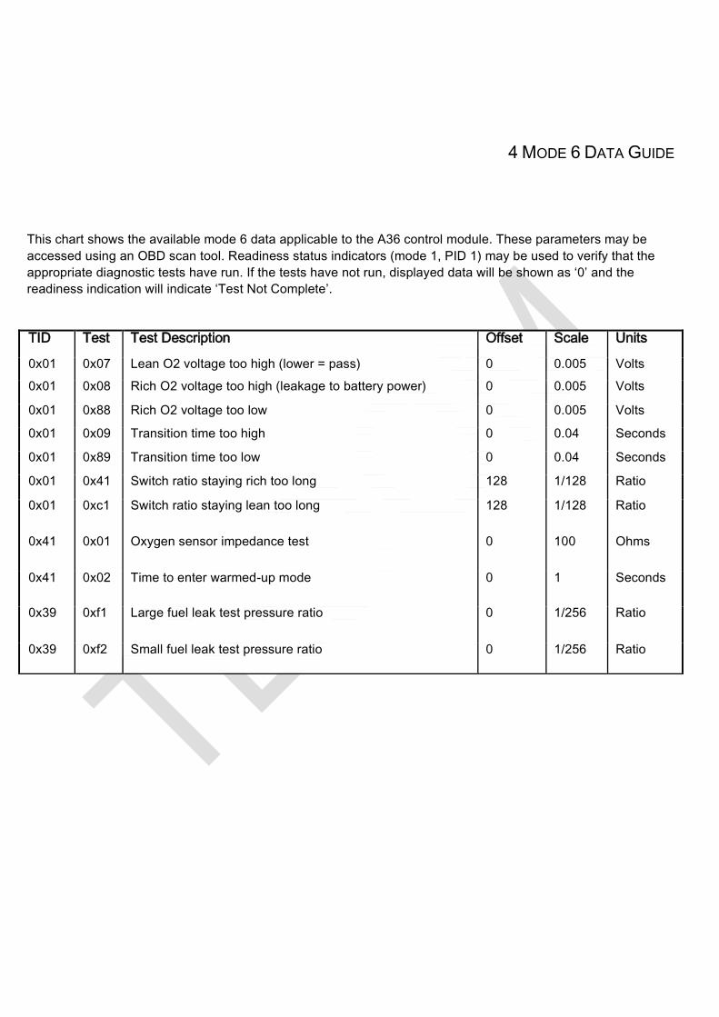
4 MODE 6 DATA GUIDE
This chart shows the available mode 6 data applicable to the A36 control module. These parameters may be
accessed using an OBD scan tool. Readiness status indicators (mode 1, PID 1) may be used to verify that the
appropriate diagnostic tests have run. If the tests have not run, displayed data will be shown as ‘0’ and the
readiness indication will indicate ‘Test Not Complete’.
TID Test Test Description Offset Scale Units
0x01 0x07 Lean O2 voltage too high (lower = pass) 0 0.005 Volts
0x01 0x08 Rich O2 voltage too high (leakage to battery power) 0 0.005 Volts
0x01 0x88 Rich O2 voltage too low 0 0.005 Volts
0x01 0x09 Transition time too high 0 0.04 Seconds
0x01 0x89 Transition time too low 0 0.04 Seconds
0x01 0x41 Switch ratio staying rich too long 128 1/128 Ratio
0x01 0xc1 Switch ratio staying lean too long 128 1/128 Ratio
0x41 0x01 Oxygen sensor impedance test 0 100 Ohms
0x41 0x02 Time to enter warmed-up mode 0 1 Seconds
0x39 0xf1 Large fuel leak test pressure ratio 0 1/256 Ratio
0x39 0xf2 Small fuel leak test pressure ratio 0 1/256 Ratio
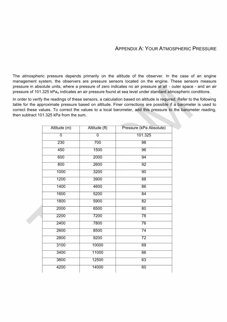
APPENDIX A: YOUR ATMOSPHERIC PRESSURE
The atmospheric pressure depends primarily on the altitude of the observer. In the case of an engine
management system, the observers are pressure sensors located on the engine. These sensors measure
pressure in absolute units, where a pressure of zero indicates no air pressure at all - outer space - and an air
pressure of 101.325 kPaa indicates an air pressure found at sea level under standard atmospheric conditions.
In order to verify the readings of these sensors, a calculation based on altitude is required. Refer to the following
table for the approximate pressure based on altitude. Finer corrections are possible if a barometer is used to
correct these values. To correct the values to a local barometer, add this pressure to the barometer reading,
then subtract 101.325 kPa from the sum.
Altitude (m) Altitude (ft) Pressure (kPa Absolute)
0 0 101.325
230 700 98
450 1500 96
600 2000 94
800 2600 92
1000 3200 90
1200 3900 88
1400 4600 86
1600 5200 84
1800 5900 82
2000 6500 80
2200 7200 78
2400 7800 76
2600 8500 74
2800 9200 72
3100 10000 69
3400 11000 66
3800 12500 63
4200 14000 60