DHC-2 Beaver ARF - greathobbies.com Official AMA National Model Aircraft Safety Code ...47. E-flite...
52
Specifications Wingspan: 68 in (1735mm) Length: 43 in (1090mm) Wing Area: 565 sq in (36.4 sq dm) Weight w/ Battery: 4.9–6.2 lb (2.2–2.8 kg) Weight w/o Battery: 4–4.25 oz (1.8–1.9 kg) DHC-2 Beaver ARF Assembly Manual
Transcript of DHC-2 Beaver ARF - greathobbies.com Official AMA National Model Aircraft Safety Code ...47. E-flite...
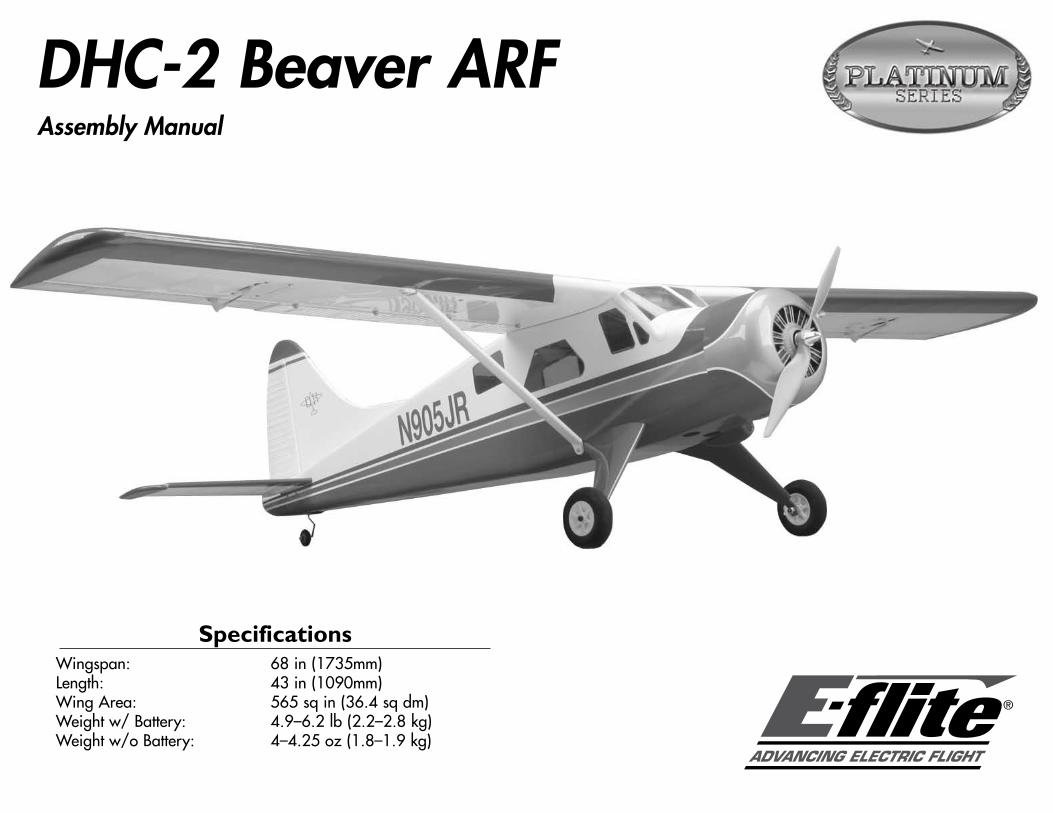
SpecificationsWingspan: 68 in (1735mm)Length: 43 in (1090mm)Wing Area: 565 sq in (36.4 sq dm)Weight w/ Battery: 4.9–6.2 lb (2.2–2.8 kg)Weight w/o Battery: 4–4.25 oz (1.8–1.9 kg)
DHC-2 Beaver ARFAssembly Manual

2 E-flite DHC-2 Beaver ARF Assembly Manual
IntroductionThe full-scale DHC-2 Beaver was originally intended for flight in areas of remote wilderness. Designed to be particularly durable and powerful, the Beaver could easily be fitted with wheels, skis or floats depending on where it was needed. The Beaver had short takeoff and landing capabilities, making it perfect to reach areas that could normally only be accessed via boat or foot. Originally designed in 1948, the Beaver quickly made itself useful flying to frozen areas of Canada and Alaska. Despite the fact that production ceased in 1967, it is still used today for island-hopping tourists and fishermen.
E-flite’s DHC-2 Beaver 25e is part of the Platinum Series, meaning the level of scale detail is unmatched. Just a few of its amazing details include corrugated flight surfaces, concealed tail linkages and a scale dummy motor. Also included with the E-flite Beaver are float mounts built into the fuselage and the wire struts required to bolt the floats onto. For additional fun, the pilot can quickly change the landing gear to the optional float set (EFLA500) for water takeoffs and landings.
For anyone looking for an authentic-looking replica of a durable utility plane with amazing scale detail that is easy to assemble, the Beaver is the sport utility vehicle of aircraft.
Platinum Series StatementOur Platinum Series delivers superior, enhanced features and meticulous attention to detail. The symbol on this kit is your assurance of excellence and one more way that E-flite brings you the most advanced electric flight experience.
Table of ContentsSpecifications ...................................................................... 1Introduction ......................................................................... 2Platinum Series Statement .................................................... 2Using the Manual ................................................................ 2Contents of Kit/Parts Layout ................................................. 3Required Radio Equipment ................................................... 4Important Information About Motor Selection ........................ 4Outrunner Setup Power 25 .................................................. 4Outrunner Setup Power 32 (recommended when using floats) 4Optional Accessories ........................................................... 5Required Tools and Adhesives .............................................. 5Notes Regarding Servos and ESC ........................................ 6Note on Lithium Polymer Batteries ........................................ 6Warning ............................................................................. 6Warranty Information .......................................................... 6Safety, Precautions, and Warnings ....................................... 8Landing Gear Installation ..................................................... 9Motor and Cowling Installation .......................................... 10Aileron and Flap Servo Installation ..................................... 15Joining the Wing Panels .................................................... 23Rudder and Elevator Installation ......................................... 25Radio Installation ............................................................... 31Optional Float Installation .................................................. 38Widows and Optional Cockpit Installation .......................... 40Control Throws .................................................................. 44Range Test Your Radio ....................................................... 45Center of Gravity .............................................................. 45Preflight ............................................................................ 46Flying Your DHC-2 Beaver ARF .......................................... 462008 Official AMA National Model Aircraft Safety Code ... 47

3E-flite DHC-2 Beaver ARF Assembly Manual
Using the ManualThis manual is divided into sections to help make assembly easier to understand, and to provide breaks between each major section. In addition, check boxes have been placed next to each step to keep track of each step completed. Steps with a single circle () are performed once, while steps with two circles ( ) indicate that the step will require repeating, such as for a right or left wing panel, two servos, etc.
Remember to take your time and follow the directions.
Contents of Kit/Parts LayoutLarge Parts:EFL4526 Wing SetEFL4527 FuselageEFL4528 Tail Set
Small parts:EFL4529 CowlingEFL4530 Window SetEFL4531 Landing GearEFL4532 Battery HatchEFL4533 Pushrod SetEFL4534 Tailwheel SetEFL4535 Wing StrutsEFL4536 Float MountEFL4538 TailconeEFL4539 Dummy Motor

4 E-flite DHC-2 Beaver ARF Assembly Manual
Required Radio Equipment
You will need a minimum 6-channel transmitter (for proper mixing and dual rate capabilities), crystals, receiver, and six mini servos. You can choose to purchase a complete radio system. If you are using an existing transmitter, just purchase the other required equipment separately. We recommend the crystal-free, interference-free Spektrum™ DX6i 2.4GHz DSM® 6-channel system. If using your own transmitter, we recommend the JR SPORT™ MN48 Mini servos.
If you own the Spektrum DX6i radio, just add the AR6200 DSM2™ 6-channel receiver and six of our JR SPORT MN48 Mini servos.Complete Radio System
SPM6600 DX6i DSM 6CH systemOr Purchase Separately
JRPR720UL UltraLite 7-Channel ScanSelect FM Receiver (72MHz)
JRP790UL UltraLite 7-Channel ScanSelect PCM Receiver (72MHz)
OrSPMAR6200 AR6200 DSM2 6-Channel Receiver
UltraLite (for DX6i on DX7)Or
SPM6070 AR7000 DSM2 7CH Rx (for DX6i or DX7)And
JSP20040 MN48 Mini Servo (6)JSP98100 3-inch Servo Extension (2)JSP98020 6-inch Y-Harness (2)JRPA096 9-inch Servo ExtensionJSP98030 12-inch Servo Extension (2)
Important Information About Motor Selection
We recommend the E-flite® Power 25 Brushless Outrunner, 870Kv (EFLM4025A) or the E-flite Power 32 Brushless Outrunner, 770Kv (EFLM4032A) if you plan on flying with the optional floats.
Outrunner Setup Power 25EFLM4025A Power 25 BL Outrunner, 870KvEFLA1060 60-Amp Brushless ESCEFLB32003S 3200mAh 3-Cell 11.1V Li-PoAPC12080E 12 x 8 Electric Prop
Outrunner Setup Power 32 (Recommended when using floats)
EFLM4032A Power 32 BL Outrunner, 770KvEFLA1060 60-Amp Brushless ESCTHP33004SX 3300mAh 4-Cell 14.8V Li-PoAPC13065E 13 x 6.5E Electric Prop
Spektrum is used with permission of Bachmann Industries, Inc.
5E-flite DHC-2 Beaver ARF Assembly Manual
Optional AccessoriesEFLA110 Power MeterEFL4537 Cockpit KitEFLA151 Pilot BustEFLA500 25-Size Fiberglass FloatsEFLAEC303 EC3 Device & Battery Connector,
Male/FemaleEFLC3005 Celectra 1- to 3-Cell Li-Po ChargerEFLC505 Intelligent 1- to 5-Cell Balancing Charger
Required Tools and AdhesivesTools & Equipment
EFLA250 Park Flyer Tool Assortment, 5-pieceOr Purchase Separately
EFLA257 Screwdriver, #1 and #2 Phillips (or included with EFLA250)
EFLA251 Hex Wrench: 3/32-inch (or included with EFLA250)
6-minute epoxyCanopy glueCovering ironDrillDrill bit: 1/16-inch (1.5mm), 5/64-inch (2mm), 1/8-inch (3mm)Felt-tipped penFlat blade screwdriverHobby knife (#11 blade)Low-tack tapeMedium CA
PencilPhillips screwdriver: #1, #2Pin drillRotary tool w/sanding drumRulerSandpaperSide cuttersThin CAThreadlockEpoxy brushPaper towelsEpoxy mixing cupsMixing sticksSquareSilicone adhesiveStringHobby scissorsBall Driver: 3/32-inch, 7/64-inchRubbing alcohol30-minute epoxy

6 E-flite DHC-2 Beaver ARF Assembly Manual
Notes Regarding Servos and ESC
WARNING: Use of servos other than those we recommend may overload the BEC of the recommended Electronic Speed Control (ESC). We suggest the use of only the servos we recommend when utilizing the recommended ESC’s BEC, or the use of a separate BEC (like the UBEC) or receiver battery pack when using other servos.
Note on Lithium Polymer BatteriesLithium Polymer batteries are significantly more volatile than alkaline or Ni-Cd/Ni-MH batteries used in RC applications. All manufacturer’s instructions and warnings must be followed closely. Mishandling of Li-Po batteries can result in fire. Always follow the manufacturer’s instructions when disposing of Lithium Polymer batteries.
WarningAn RC aircraft is not a toy! If misused, it can cause serious bodily harm and damage to property. Fly only in open areas, preferably at AMA (Academy of Model Aeronautics) approved flying sites, following all instructions included with your radio.
Keep loose items that can get entangled in the propeller away from the prop, including loose clothing, or other objects such as pencils and screwdrivers. Especially keep your hands away from the propeller.
Warranty Information
Warranty PeriodHorizon Hobby, Inc., (Horizon) warranties that the Products purchased (the “Product”) will be free from defects in materials and workmanship at the date of purchase by the Purchaser.
Limited Warranty(a) This warranty is limited to the original Purchaser ("Purchaser") and is not transferable. REPAIR OR REPLACEMENT AS PROVIDED UNDER THIS WARRANTY IS THE EXCLUSIVE REMEDY OF THE PURCHASER. This warranty covers only those Products purchased from an authorized Horizon dealer. Third party transactions are not covered by this warranty. Proof of purchase is required for warranty claims. Further, Horizon reserves the right to change or modify this warranty without notice and disclaims all other warranties, express or implied.
(b) Limitations- HORIZON MAKES NO WARRANTY OR REPRESENTATION, EXPRESS OR IMPLIED, ABOUT NON-INFRINGEMENT, MERCHANTABILITY OR FITNESS FOR A PARTICULAR PURPOSE OF THE PRODUCT. THE PURCHASER ACKNOWLEDGES THAT THEY ALONE HAVE DETERMINED THAT THE PRODUCT WILL SUITABLY MEET THE REQUIREMENTS OF THE PURCHASER’S INTENDED USE.
(c) Purchaser Remedy- Horizon's sole obligation hereunder shall be that Horizon will, at its option, (i) repair or (ii) replace, any Product determined by Horizon to be defective. In the event of a defect, these are the Purchaser's exclusive remedies. Horizon reserves the right to inspect any and all equipment involved in a warranty claim. Repair or replacement decisions are at the sole discretion of Horizon. This warranty does not cover cosmetic damage or damage due to acts of God, accident, misuse, abuse, negligence, commercial use, or modification of or to any part of the Product. This warranty does not cover damage due to improper installation, operation, maintenance, or attempted repair by anyone other than Horizon. Return of any goods by Purchaser must be approved in writing by Horizon before shipment.

7E-flite DHC-2 Beaver ARF Assembly Manual
Damage LimitsHORIZON SHALL NOT BE LIABLE FOR SPECIAL, INDIRECT OR CONSEQUENTIAL DAMAGES, LOSS OF PROFITS OR PRODUCTION OR COMMERCIAL LOSS IN ANY WAY CONNECTED WITH THE PRODUCT, WHETHER SUCH CLAIM IS BASED IN CONTRACT, WARRANTY, NEGLIGENCE, OR STRICT LIABILITY. Further, in no event shall the liability of Horizon exceed the individual price of the Product on which liability is asserted. As Horizon has no control over use, setup, final assembly, modification or misuse, no liability shall be assumed nor accepted for any resulting damage or injury. By the act of use, setup or assembly, the user accepts all resulting liability.
If you as the Purchaser or user are not prepared to accept the liability associated with the use of this Product, you are advised to return this Product immediately in new and unused condition to the place of purchase.
Law: These Terms are governed by Illinois law (without regard to conflict of law principals).
Safety PrecautionsThis is a sophisticated hobby Product and not a toy. It must be operated with caution and common sense and requires some basic mechanical ability. Failure to operate this Product in a safe and responsible manner could result in injury or damage to the Product or other property. This Product is not intended for use by children without direct adult supervision. The Product manual contains instructions for safety, operation and maintenance. It is essential to read and follow all the instructions and warnings in the manual, prior to assembly, setup or use, in order to operate correctly and avoid damage or injury.
Questions, Assistance, and RepairsYour local hobby store and/or place of purchase cannot provide warranty support or repair. Once assembly, setup or use of the Product has been started, you must contact Horizon directly. This will enable Horizon to better answer your questions and service you in the event that you may need any assistance. For questions or assistance, please direct your email to [email protected], or call 877.504.0233 toll free to speak to a service technician.
Inspection or RepairsIf this Product needs to be inspected or repaired, please call for a Return Merchandise Authorization (RMA). Pack the Product securely using a shipping carton. Please note that original boxes may be included, but are not designed to withstand the rigors of shipping without additional protection. Ship via a carrier that provides tracking and insurance for lost or damaged parcels, as Horizon is not responsible for merchandise until it arrives and is accepted at our facility. A Service Repair Request is available at www.horizonhobby.com on the “Support” tab. If you do not have internet access, please include a letter with your complete name, street address, email address and phone number where you can be reached during business days, your RMA number, a list of the included items, method of payment for any non-warranty expenses and a brief summary of the problem. Your original sales receipt must also be included for warranty consideration. Be sure your name, address, and RMA number are clearly written on the outside of the shipping carton.
Warranty Inspection and RepairsTo receive warranty service, you must include your original sales receipt verifying the proof-of-purchase date. Provided warranty conditions have been met, your Product will be repaired or replaced free of charge. Repair or replacement decisions are at the sole discretion of Horizon Hobby.
8 E-flite DHC-2 Beaver ARF Assembly Manual
Non-Warranty RepairsShould your repair not be covered by warranty the repair will be completed and payment will be required without notification or estimate of the expense unless the expense exceeds 50% of the retail purchase cost. By submitting the item for repair you are agreeing to payment of the repair without notification. Repair estimates are available upon request. You must include this request with your repair. Non-warranty repair estimates will be billed a minimum of ½ hour of labor. In addition you will be billed for return freight. Please advise us of your preferred method of payment. Horizon accepts money orders and cashiers checks, as well as Visa, MasterCard, American Express, and Discover cards. If you choose to pay by credit card, please include your credit card number and expiration date. Any repair left unpaid or unclaimed after 90 days will be considered abandoned and will be disposed of accordingly. Please note: non-warranty repair is only available on electronics and model engines.Electronics and engines requiring inspection or repair should be shipped to the following address:
Horizon Service Center 4105 Fieldstone Road
Champaign, Illinois 61822
All other Products requiring warranty inspection or repair should be shipped to the following address:
Horizon Product Support 4105 Fieldstone Road
Champaign, Illinois 61822
Please call 877-504-0233 with any questions or concerns regarding this product or warranty.
Safety, Precautions, and WarningsAs the user of this product, you are solely responsible for operating it in a manner that does not endanger yourself and others or result in damage to the product or the property of others.
Carefully follow the directions and warnings for this and any optional support equipment (chargers, rechargeable battery packs, etc.) that you use.
This model is controlled by a radio signal that is subject to interference from many sources outside your control. This interference can cause momentary loss of control so it is necessary to always keep a safe distance in all directions around your model, as this margin will help to avoid collisions or injury.
• Always operate your model in an open area away from cars, traffic, or people.
• Avoid operating your model in the street where injury or damage can occur.
• Never operate the model out into the street or populated areas for any reason.
• Never operate your model with low transmitter batteries.
• Carefully follow the directions and warnings for this and any optional support equipment (chargers, rechargeable battery packs, etc.) that you use.
• Keep all chemicals, small parts and anything electrical out of the reach of children.
• Moisture causes damage to electronics. Avoid water exposure to all equipment not specifically designed and protected for this purpose.

9E-flite DHC-2 Beaver ARF Assembly Manual
Landing Gear InstallationRequired Parts
Fuselage Landing gear (right and left)6-32 x 3/8-inch socket head screw (4)#6 washer (4)
Required Tools and AdhesivesBall driver: 7/64-inch Threadlock
Note: If you will be installing floats on your DHC-2 Beaver, you can skip to the next section to install the motor and battery.
1. Check the fit of the landing gear in the fuselage. Note that there is a right and left landing gear assembly.
2. Secure the left half of the landing gear using two 6-32 x 3/8-inch socket head screws and two #6 washers. Use a 7/64-inch ball driver to tighten the screws.
Note: Make sure to use threadlock on all screws so they do not vibrate loose.
10 E-flite DHC-2 Beaver ARF Assembly Manual
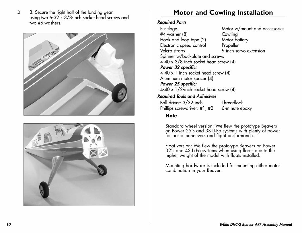
3. Secure the right half of the landing gear using two 6-32 x 3/8-inch socket head screws and two #6 washers.
Motor and Cowling InstallationRequired Parts
Fuselage Motor w/mount and accessories#4 washer (8) CowlingHook and loop tape (2) Motor batteryElectronic speed control PropellerVelcro straps 9-inch servo extensionSpinner w/backplate and screws4-40 x 3/8-inch socket head screw (4)Power 32 specific:4-40 x 1-inch socket head screw (4)Aluminum motor spacer (4)Power 25 specific:4-40 x 1/2-inch socket head screw (4)
Required Tools and AdhesivesBall driver: 3/32-inch ThreadlockPhillips screwdriver: #1, #2 6-minute epoxy
Note
Standard wheel version: We flew the prototype Beavers on Power 25's and 3S Li-Po systems with plenty of power for basic maneuvers and flight performance.
Float version: We flew the prototype Beavers on Power 32's and 4S Li-Po systems when using floats due to the higher weight of the model with floats installed.
Mounting hardware is included for mounting either motor combination in your Beaver.

11E-flite DHC-2 Beaver ARF Assembly Manual
1. Attach the X-Mount to the motor using the screws provided with the motor and a #2 Phillips screwdriver. Make sure to use threadlock on all four screws so they do not vibrate loose.
2a. Attach the Power 32 motor to the firewall using four 4-40 x 1-inch socket head screws, four #4 washers, four aluminum motor spacers. Tighten the screws using a 3/32-inch ball driver. Make sure to use threadlock on the four screws to prevent them from vibrating loose.
2b. Attach the Power 25 motor to the firewall using four 4-40 x 1/2-inch socket head screws and four #4 washers. Tighten the screws using a 3/32-inch ball driver. Make sure to use threadlock on the four screws to prevent them from vibrating loose.
Note: The blind nuts in the fuselage for mounting the motor can be positioned for a variety of motors. Position them so they are aligned with your particular motor before mounting it to the firewall.
12 E-flite DHC-2 Beaver ARF Assembly Manual
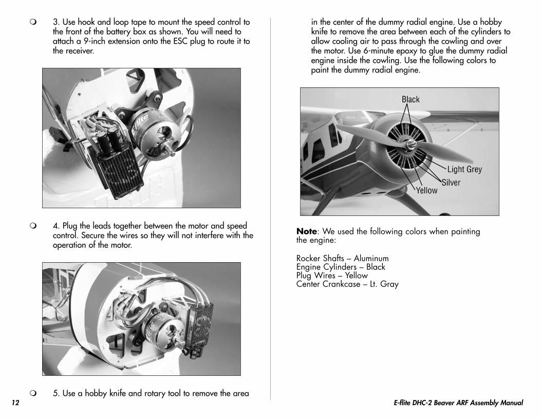
3. Use hook and loop tape to mount the speed control to the front of the battery box as shown. You will need to attach a 9-inch extension onto the ESC plug to route it to the receiver.
4. Plug the leads together between the motor and speed control. Secure the wires so they will not interfere with the operation of the motor.
5. Use a hobby knife and rotary tool to remove the area
in the center of the dummy radial engine. Use a hobby knife to remove the area between each of the cylinders to allow cooling air to pass through the cowling and over the motor. Use 6-minute epoxy to glue the dummy radial engine inside the cowling. Use the following colors to paint the dummy radial engine.
Note: We used the following colors when painting the engine:
Rocker Shafts – Aluminum Engine Cylinders – Black Plug Wires – Yellow Center Crankcase – Lt. Gray

13E-flite DHC-2 Beaver ARF Assembly Manual
6. Attach the cowl to the fuselage using four 4-40 x 3/8-inch socket head screws and four #4 washers. Note the direction of the cowl as shown in the photo. Use a 3/32-inch ball driver to tighten the screws that secure the cowling. Use threadlock to ensure the screws do not come loose during flight.
Important Information About Your Propeller
It is also very important to check to be sure the propeller is balanced before installing onto the shaft. An unbalanced propeller may strip the gears or cause poor flight characteristics.
Note: If it is necessary to enlarge the hole in the propeller, make sure to check the balance of the propeller afterwards.
Note: Some DHC-2 beaver's utilized a spinner and some did not. We have included a spinner for you if you so wish to use one. On the model we have represented, we did not use a spinner; we used only a prop nut.
7. Insert the propeller adapter into the spinner backplate. It may be necessary to enlarge to hole in the backplate to accept the adapter.
8. Slide the adapter onto the motor shaft, then slide the propeller onto the adapter. Use the adapter nut to secure the propeller and spinner backplate to the motor shaft.
14 E-flite DHC-2 Beaver ARF Assembly Manual
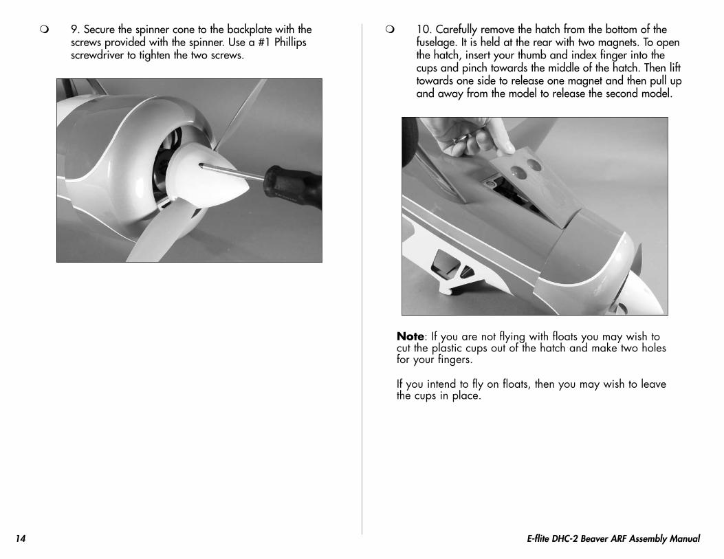
9. Secure the spinner cone to the backplate with the screws provided with the spinner. Use a #1 Phillips screwdriver to tighten the two screws.
10. Carefully remove the hatch from the bottom of the fuselage. It is held at the rear with two magnets. To open the hatch, insert your thumb and index finger into the cups and pinch towards the middle of the hatch. Then lift towards one side to release one magnet and then pull up and away from the model to release the second model.
Note: If you are not flying with floats you may wish to cut the plastic cups out of the hatch and make two holes for your fingers.
If you intend to fly on floats, then you may wish to leave the cups in place.
15E-flite DHC-2 Beaver ARF Assembly Manual
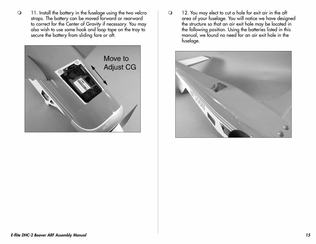
11. Install the battery in the fuselage using the two velcro straps. The battery can be moved forward or rearward to correct for the Center of Gravity if necessary. You may also wish to use some hook and loop tape on the tray to secure the battery from sliding fore or aft.
12. You may elect to cut a hole for exit air in the aft area of your fuselage. You will notice we have designed the structure so that an air exit hole may be located in the following position. Using the batteries listed in this manual, we found no need for an air exit hole in the fuselage.

16 E-flite DHC-2 Beaver ARF Assembly Manual
Aileron and Flap Servo InstallationRequired Parts
Wing panel (right and left) Aileron servo cover (right and left)Servo mounting blocks (8) Nylon clevis (4)Clevis retainer (4) Pushrod connector (4)Flap servo cover (2) 2
1/2-inch (58mm) pushrod (2)2
3/16-inch (56mm) pushrod (2)Servo extension, 3-inch (76mm) (2)Servo extension, 12-inch (305mm) (2)#2 x 3/8-inch sheet metal screw (16)
Required Tools and AdhesivesThin CA Pin drillDrill Side cuttersPhillips screwdriver: #1 PencilString RulerLow-tack tape 6-minute epoxyDrill bit: 1/16-inch (1.5mm), 5/64-inch (2mm)
1. Position the aileron servo on the servo cover so the arm is centered lengthwise in the cutout. The arm will align with the edge of the servo cover as well. Use a pencil to mark the position of the servo on the cover.
2. Use 6-minute epoxy to glue the servo mounting block to the servo cover as shown. Allow the epoxy to fully cure before proceeding.

17E-flite DHC-2 Beaver ARF Assembly Manual
3. Position the servo between the servo mounting block. Use a pencil to mark the locations for the servo mounting screws on the blocks. The servo should not touch the cover to prevent it from absorbing vibrations from the airframe. You may have to notch the servo block to allow access for the servo wire.
4. Use a drill and 1/16-inch (1.5mm) drill bit to drill the holes for the servo mounting screws.
5. Apply a few drops of thin CA to each of the holes drilled in the previous step to harden the surrounding wood.
18 E-flite DHC-2 Beaver ARF Assembly Manual
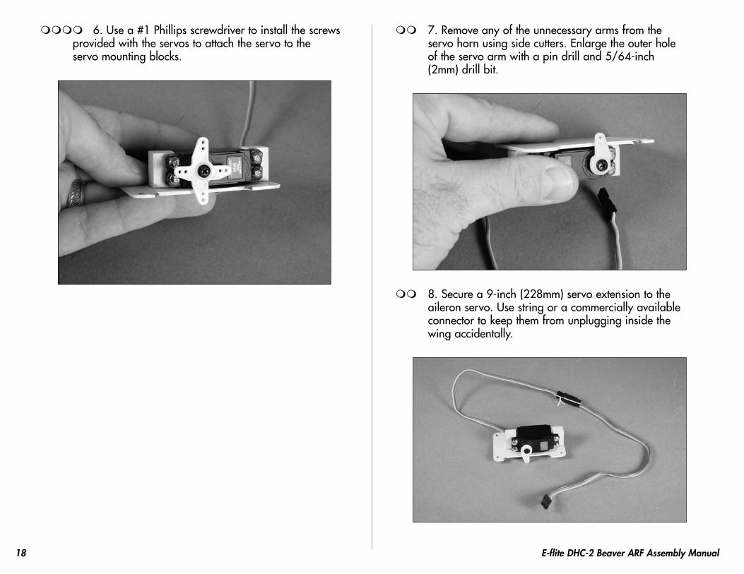
6. Use a #1 Phillips screwdriver to install the screws provided with the servos to attach the servo to the servo mounting blocks.
7. Remove any of the unnecessary arms from the servo horn using side cutters. Enlarge the outer hole of the servo arm with a pin drill and 5/64-inch (2mm) drill bit.
8. Secure a 9-inch (228mm) servo extension to the aileron servo. Use string or a commercially available connector to keep them from unplugging inside the wing accidentally.
19E-flite DHC-2 Beaver ARF Assembly Manual
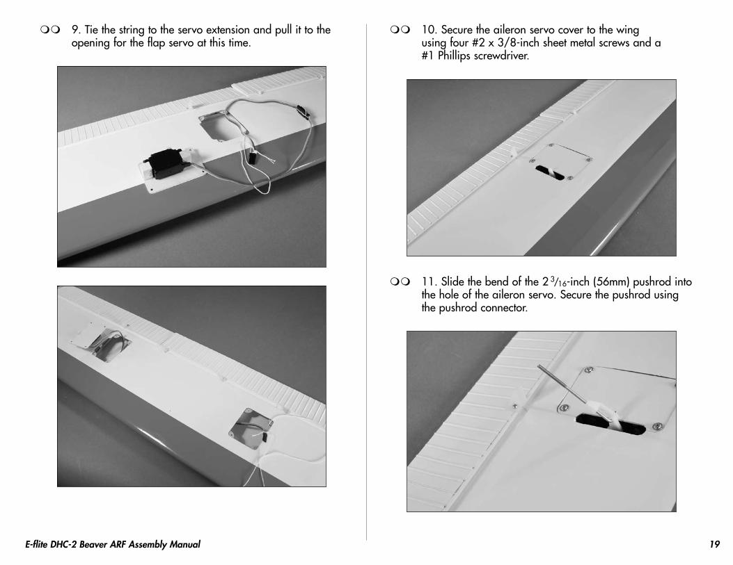
9. Tie the string to the servo extension and pull it to the opening for the flap servo at this time.
10. Secure the aileron servo cover to the wing using four #2 x 3/8-inch sheet metal screws and a #1 Phillips screwdriver.
11. Slide the bend of the 2 3/16-inch (56mm) pushrod into
the hole of the aileron servo. Secure the pushrod using the pushrod connector.
20 E-flite DHC-2 Beaver ARF Assembly Manual
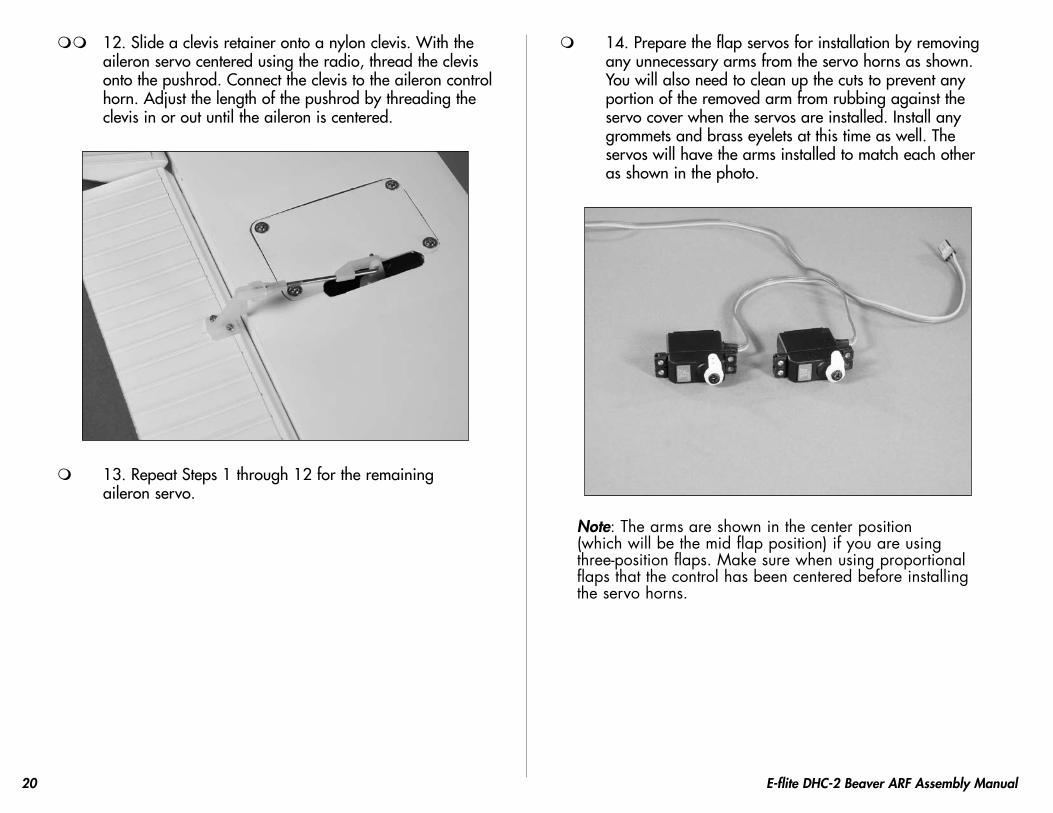
12. Slide a clevis retainer onto a nylon clevis. With the aileron servo centered using the radio, thread the clevis onto the pushrod. Connect the clevis to the aileron control horn. Adjust the length of the pushrod by threading the clevis in or out until the aileron is centered.
13. Repeat Steps 1 through 12 for the remaining aileron servo.
14. Prepare the flap servos for installation by removing any unnecessary arms from the servo horns as shown. You will also need to clean up the cuts to prevent any portion of the removed arm from rubbing against the servo cover when the servos are installed. Install any grommets and brass eyelets at this time as well. The servos will have the arms installed to match each other as shown in the photo.
Note: The arms are shown in the center position (which will be the mid flap position) if you are using three-position flaps. Make sure when using proportional flaps that the control has been centered before installing the servo horns.

21E-flite DHC-2 Beaver ARF Assembly Manual
15. Using a ruler, mark the servo cover as shown using a pencil.
16. Repeat Steps 1 through 6 to attach the flap servo to the servo cover. Align the servo arm on the intersection of the lines drawn in the previous step.
17. Secure a 3-inch (76mm) extension to the flap servo lead. Tie the string to the flap servo extension and pull both the aileron and flap leads to the hole in the bottom of the wing. Use tape to keep the leads from falling back into the wing.
22 E-flite DHC-2 Beaver ARF Assembly Manual
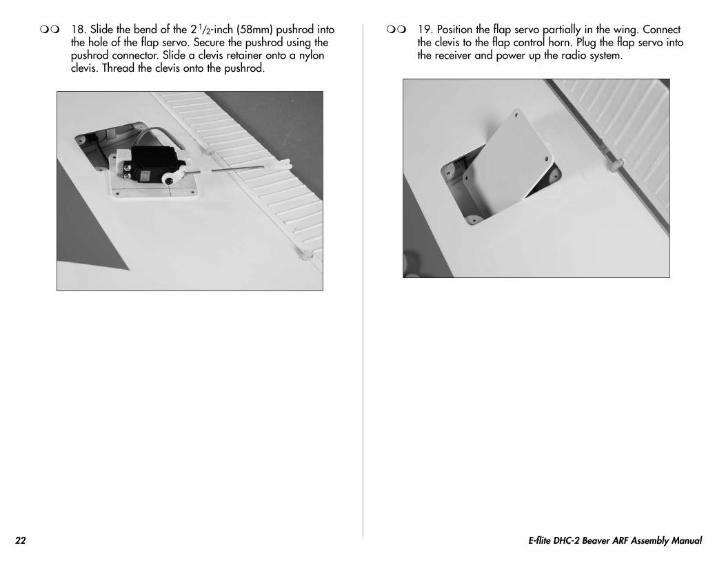
18. Slide the bend of the 2 1/2-inch (58mm) pushrod into
the hole of the flap servo. Secure the pushrod using the pushrod connector. Slide a clevis retainer onto a nylon clevis. Thread the clevis onto the pushrod.
19. Position the flap servo partially in the wing. Connect the clevis to the flap control horn. Plug the flap servo into the receiver and power up the radio system.
23E-flite DHC-2 Beaver ARF Assembly Manual
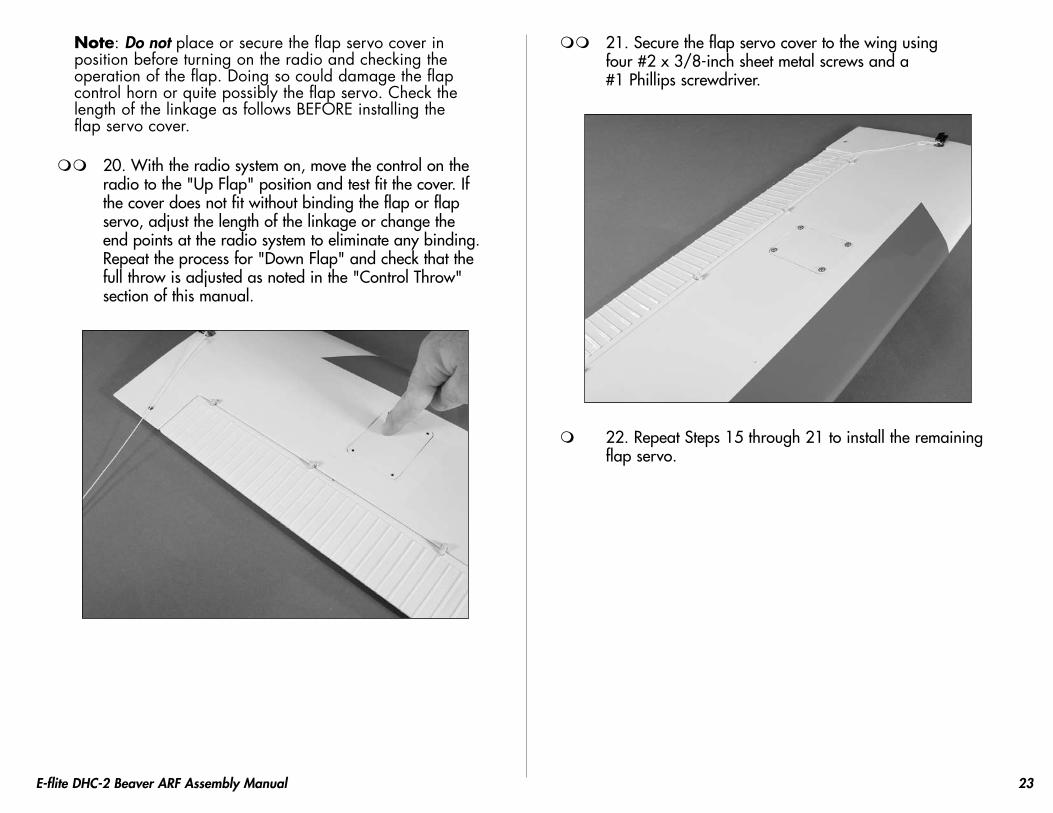
Note: Do not place or secure the flap servo cover in position before turning on the radio and checking the operation of the flap. Doing so could damage the flap control horn or quite possibly the flap servo. Check the length of the linkage as follows BEFORE installing the flap servo cover.
20. With the radio system on, move the control on the radio to the "Up Flap" position and test fit the cover. If the cover does not fit without binding the flap or flap servo, adjust the length of the linkage or change the end points at the radio system to eliminate any binding. Repeat the process for "Down Flap" and check that the full throw is adjusted as noted in the "Control Throw" section of this manual.
21. Secure the flap servo cover to the wing using four #2 x 3/8-inch sheet metal screws and a #1 Phillips screwdriver.
22. Repeat Steps 15 through 21 to install the remaining flap servo.

24 E-flite DHC-2 Beaver ARF Assembly Manual
Joining the Wing PanelsRequired Parts
Wing panel (right and left) Wing joinerWhite covering strip 1/2-inch x 10-inch (13mm x 254mm)
Required Tools and Adhesives30-minute epoxy PencilMixing sticks Epoxy brushEpoxy mixing cup Paper towelsRubbing alcohol Low-tack tapeSandpaper Trim iron
1. Mark the wing joiner and the wing panels so the joiner can easily be positioned consistently during the joining of the wings.
2. Slide the wing joiner into the wing panel. Use a pencil to mark the joiner against the wing. The joiner should fit snug in the wing. If it does not fit, lightly sand the joiner until it does fit nicely.
3. Slide the joiner into the opposite wing panel. It should slide in to slightly hide the line drawn in the previous step. If not, lightly sand the ends of the joiner until it fits equally into both wing panels.

25E-flite DHC-2 Beaver ARF Assembly Manual
Note: The following steps will be performed while you have epoxy mixed. Make sure the steps can be performed before the epoxy begins to cure. It is suggested to make a test run of the steps if you are unsure of the procedure.
4. Mix up some 30-minute epoxy and apply it to one half of the joiner. Make sure to coat the top, bottom and both sides of the joiner.
5. Coat the root rib of the wing panel with epoxy. Apply epoxy into the opening for the joiner as well.
6. Slide the joiner into the wing panel. Apply epoxy to the joiner and to the wing as described in Step 5 and slide the two wing panels together.

26 E-flite DHC-2 Beaver ARF Assembly Manual
7. Use low-tack tape to hold the two wing panels tightly together until the epoxy fully cures.
Note: You may use rubbing alcohol and paper towels to clean up any epoxy that might have spilt on the wings during this process before the epoxy hardens.
8. Using a trim iron, iron on the piece of white ultra cote to seal the wing joint.

27E-flite DHC-2 Beaver ARF Assembly Manual
Rudder and Elevator InstallationRequired Parts
Fuselage Rudder/fin assemblyStabilizer/elevator assembly Rudder control hornTail wheel assembly Tail wheel control hornNylon wing bolt (2) Wing strut (2)Wing assembly#2 x 3/8-inch sheet metal screw (4)
Required Tools and AdhesivesPhillips screwdriver: #1 Flat blade screwdriverRuler Felt-tipped penThin CA Hobby knife w/new #11 bladeSquare ThreadlockSandpaperHex wrench (included with kit)
1. Use a #1 Phillips screwdriver to remove the four screws holding the tail cone in position. Set the screws aside in a safe location at this time.
2. Attach the wing to the fuselage using a flat blade screwdriver and the two nylon wing bolts.
3. Attach the wing struts to the wing and fuselage using two #2 x 3/8-inch sheet metal screws for each wing strut. Use a #1 Phillips screwdriver to tighten the screws. Holes have been pre-drilled for the wing strut screws in both the fuselage and the bottom of the wing.

28 E-flite DHC-2 Beaver ARF Assembly Manual
4. Slide the stabilizer into position. Center the stabilizer as shown in the photo.
A A A=A
5. Using a ruler, measure from each stabilizer tip to the corresponding wing tip. The measurements must be equal. If not, reposition the stabilizer until both measurements are equal.
A A
A=A
6. Check the alignment between the wing and stabilizer. They should be parallel to each other. If not, lightly sand the stabilizer saddle until the wing and stabilizer are in alignment with each other.
Parallel
7. Once the tail of your Beaver has been aligned, use a felt-tipped pen to trace the outline of the fuselage on the stabilizer.
29E-flite DHC-2 Beaver ARF Assembly Manual
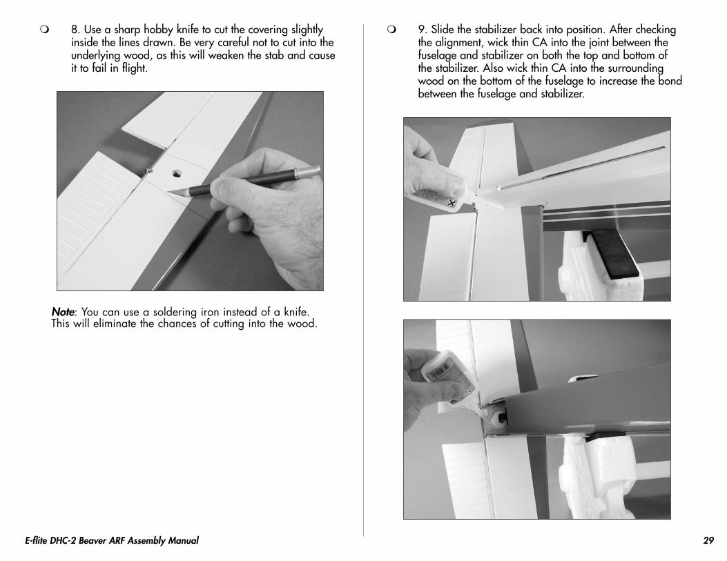
8. Use a sharp hobby knife to cut the covering slightly inside the lines drawn. Be very careful not to cut into the underlying wood, as this will weaken the stab and cause it to fail in flight.
Note: You can use a soldering iron instead of a knife. This will eliminate the chances of cutting into the wood.
9. Slide the stabilizer back into position. After checking the alignment, wick thin CA into the joint between the fuselage and stabilizer on both the top and bottom of the stabilizer. Also wick thin CA into the surrounding wood on the bottom of the fuselage to increase the bond between the fuselage and stabilizer.

30 E-flite DHC-2 Beaver ARF Assembly Manual
10. Insert the rudder control rod into the fuselage, then slide the fin into the slot in the top of the fuselage.
11. Use a felt-tipped pen to trace the outline of the fuselage onto the fin. Also trace the outline of the dorsal fin onto the top of the fuselage.

31E-flite DHC-2 Beaver ARF Assembly Manual
12. Use a sharp hobby knife to cut the covering slightly below the lines drawn. Be very careful not to cut into the underlying wood, as this will weaken the fin and cause it to fail in flight. Also trim the covering on the top of the fuselage.
13. Check that the fin is square to the stabilizer. Sanding the bottom of the fin where it fits into the fuselage can correct for any alignment issues. A slight amount of material from the bottom of the fin might need to be removed for a correct fit.
32 E-flite DHC-2 Beaver ARF Assembly Manual
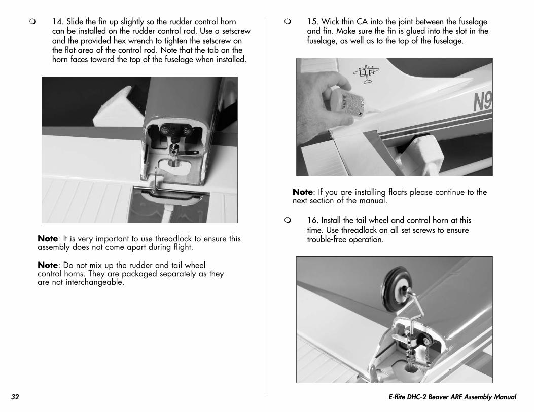
14. Slide the fin up slightly so the rudder control horn can be installed on the rudder control rod. Use a setscrew and the provided hex wrench to tighten the setscrew on the flat area of the control rod. Note that the tab on the horn faces toward the top of the fuselage when installed.
Note: It is very important to use threadlock to ensure this assembly does not come apart during flight.
Note: Do not mix up the rudder and tail wheel control horns. They are packaged separately as they are not interchangeable.
15. Wick thin CA into the joint between the fuselage and fin. Make sure the fin is glued into the slot in the fuselage, as well as to the top of the fuselage.
Note: If you are installing floats please continue to the next section of the manual.
16. Install the tail wheel and control horn at this time. Use threadlock on all set screws to ensure trouble-free operation.

33E-flite DHC-2 Beaver ARF Assembly Manual
Radio InstallationRequired Parts
Fuselage assembly Servo w/hardware (2)Brass pushrod connector Connector backplateClevis (3) Clevis retainer (3)Pushrod connector (2) 3mm setscrewHook and loop material Receiver23
7/8-inch (606mm) pushrod wire24
7/8-inch (631mm) pushrod wire25
7/8-inch (658mm) pushrod wireRequired Tools and Adhesives
Pin drill Thin CADrill bit: 1/16-inch (1.5mm), 5/64-inch (2mm)Phillips screwdriver: #1 Side cutters
1. Install the grommets and brass eyelets for the rudder servo. Use a pin drill and 5/64-inch (2mm) drill bit to enlarge the outer holes (right and left) of the servo arm.
2. Remove the two arms (front and rear) from the servo horn using side cutters.
3. Slide the brass pushrod connector into the outer hole of the servo arm as shown.

34 E-flite DHC-2 Beaver ARF Assembly Manual
4. Secure the connector using the connector backplate.
Note: If you are installing floats, prepare the rudder control horn as shown. The pushrod and brass connector will be on the same side of the servo horn.
5. Repeat Steps 1 and 2 to prepare the elevator servo.
6. Place the elevator servo into the fuselage with the output facing to the front. Use a pin drill and 1/16-inch (1.5mm) drill bit to drill the holes for the servo mounting screws.

35E-flite DHC-2 Beaver ARF Assembly Manual
7. Place 2–3 drops of thin CA into each of the holes to harden the surrounding wood. This hardens the wood and provides a better bite for the screws.
8. Install the elevator servo using the screws provided with the servo.
9. Repeat Steps 6 through 8 to install the rudder servo.
10. Slide the 23 7/8-inch (606mm) pushrod wire into the
tube inside the fuselage for the rudder pushrod.
36 E-flite DHC-2 Beaver ARF Assembly Manual
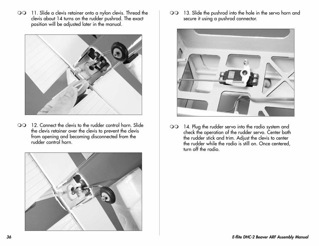
11. Slide a clevis retainer onto a nylon clevis. Thread the clevis about 14 turns on the rudder pushrod. The exact position will be adjusted later in the manual.
12. Connect the clevis to the rudder control horn. Slide the clevis retainer over the clevis to prevent the clevis from opening and becoming disconnected from the rudder control horn.
13. Slide the pushrod into the hole in the servo horn and secure it using a pushrod connector.
14. Plug the rudder servo into the radio system and check the operation of the rudder servo. Center both the rudder stick and trim. Adjust the clevis to center the rudder while the radio is still on. Once centered, turn off the radio.

37E-flite DHC-2 Beaver ARF Assembly Manual
15. Repeat Steps 11 through 14 to install the 24 7/8-inch
(631mm) elevator pushrod wire.Note: If you are planning on installing floats, skip Steps 16 and 17 as they pertain to the installation of the tail wheel linkage.
16. Place a clevis retainer on a nylon clevis and thread the clevis on the remaining pushrod wire. Slide the wire into the pushrod tube inside the fuselage and through the pushrod connector of the rudder servo. Secure the clevis to the tail wheel control horn.

38 E-flite DHC-2 Beaver ARF Assembly Manual
17. After centering the tail wheel, tighten the 3mm setscrew to secure the pushrod. Use this connection to trim the steering of your Beaver on the ground. DO NOT use the radio trim to correct the steering trim.
Note: Your kit will use a 3mm setscrew instead of the machine screw shown in the photo.
18. Install the tail cone using the screws that were removed earlier in the manual and a #1 Phillips screwdriver.

39E-flite DHC-2 Beaver ARF Assembly Manual
19. Use hook and loop tape to secure the receiver inside the fuselage. If you are using a remote receiver, secure it as far away and as far up in the fuselage as possible.
Optional Float InstallationRequired Parts
Fuselage assembly Float set w/hardwareBeaver float mount (included with kit)Landing gear plug (2)
Required Tools and AdhesivesDrill Thin CAString ThreadlockPhillips screwdriver: #2 Silicone adhesiveHex wrench (included with kit)Drill bit: 5/64-inch (2mm), 1/8-inch (3mm)
Note: The hardware used to mount the floats and struts to your Beaver is from the E-flite float set (EFLA500).
1. Install the float mount braces between the front and rear float supports as shown in the image below.
40 E-flite DHC-2 Beaver ARF Assembly Manual
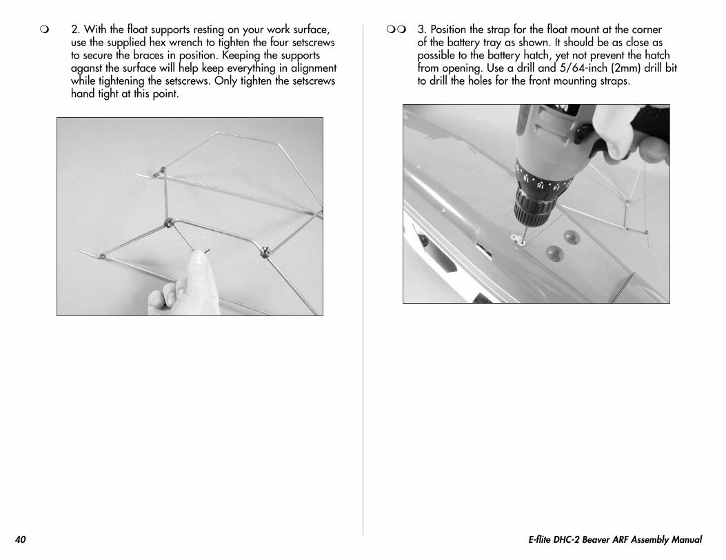
2. With the float supports resting on your work surface, use the supplied hex wrench to tighten the four setscrews to secure the braces in position. Keeping the supports aganst the surface will help keep everything in alignment while tightening the setscrews. Only tighten the setscrews hand tight at this point.
3. Position the strap for the float mount at the corner of the battery tray as shown. It should be as close as possible to the battery hatch, yet not prevent the hatch from opening. Use a drill and 5/64-inch (2mm) drill bit to drill the holes for the front mounting straps.

41E-flite DHC-2 Beaver ARF Assembly Manual
4. Attach the float mount to the bottom of the fuselage using two straps, four 3mm x 12mm sheet metal screws and a #2 Phillips screwdriver.
5. Repeat Steps 3 and 4 for the rear mounting straps. The main concern is the float mount is centered side to side on the bottom of the fuselage.
6. Using threadlock, tighten the setscrews for the cross braces on the float mount. Assemble and attach the floats to the float mounts using the instructions provided with your float set. The float with the water rudder installs on the left side of the model.

42 E-flite DHC-2 Beaver ARF Assembly Manual
7. Drill a 1/8-inch (3mm) hole in the bottom of the fuselage near the landing gear. Route the float pushrod through the hole and into the fuselage. Use silicone adhesive to glue the pushrod tube to the fuselage. Use thin CA to glue the landing gear plugs to the fuselage at this time as well. You may also opt to use clear tape to install the landing gear plugs in the fuselage if you might change from floats to wheels from time to time.
8. Connect the pushrod cable to the connector. The pushrod must be secured inside the fuselage. Wrap string around the pushrod tube and the cross member of the radio tray. Soak the string with thin CA to secure the pushrod location inside the fuselage.
43E-flite DHC-2 Beaver ARF Assembly Manual
Windows, Cockpit and Air Scoop Installation
Required PartsFuselage assembly Cockpit kit (optional)Side window set Front windscreenAir scoop (2)
Required Tools and AdhesivesCanopy glue Hobby scissorsHobby knife Low-tack tapeOptional tools:Drill Drill bit: 5/64-inch (2mm)Phillips screwdriver: #1 Medium CA
Note: If you are not installing the optional cockpit, perform Steps 4, 5, 7, 11 and 12.
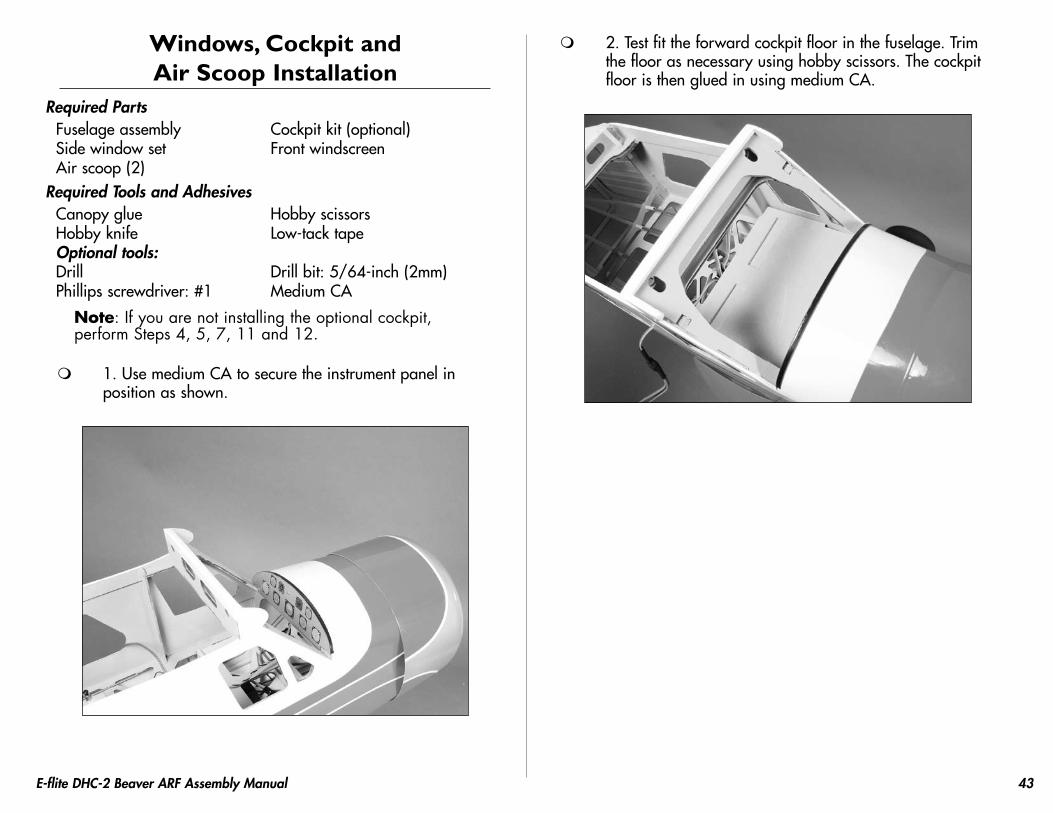
1. Use medium CA to secure the instrument panel in position as shown.
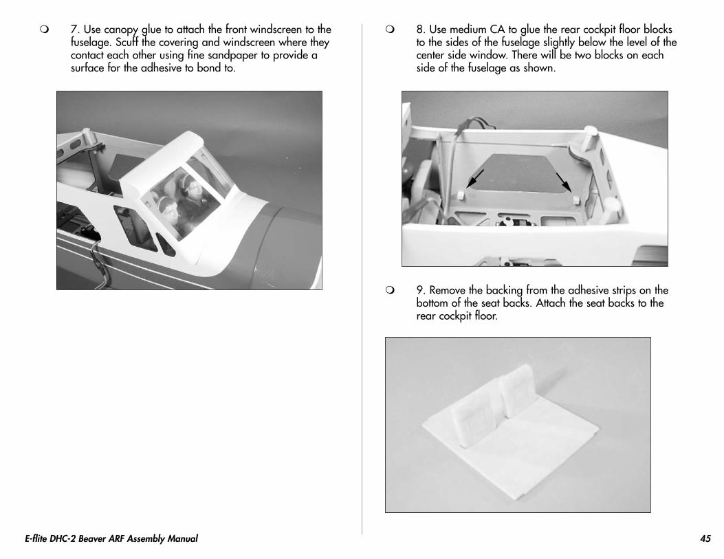
2. Test fit the forward cockpit floor in the fuselage. Trim the floor as necessary using hobby scissors. The cockpit floor is then glued in using medium CA.

44 E-flite DHC-2 Beaver ARF Assembly Manual
3. Remove the backing from the adhesive strips on the bottom of the seat backs. Attach the seat backs to the forward cockpit floor.
4. Trim the forward side windows from the window set using hobby scissors and a hobby knife.
5. Use canopy glue to secure the right and left front side windows to the inside of the fuselage.
6. Use medium CA to secure the pilot twins to the forward cockpit floor.
45E-flite DHC-2 Beaver ARF Assembly Manual
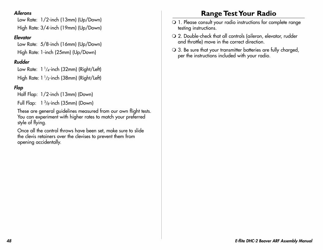
7. Use canopy glue to attach the front windscreen to the fuselage. Scuff the covering and windscreen where they contact each other using fine sandpaper to provide a surface for the adhesive to bond to.
8. Use medium CA to glue the rear cockpit floor blocks to the sides of the fuselage slightly below the level of the center side window. There will be two blocks on each side of the fuselage as shown.
9. Remove the backing from the adhesive strips on the bottom of the seat backs. Attach the seat backs to the rear cockpit floor.

46 E-flite DHC-2 Beaver ARF Assembly Manual
10. Secure the rear cockpit floor in the fuselage using four #2 x 3/8-inch sheet metal screws. The screws will go through the rear cockpit floor and into the block installed in Step 8. Route the leads for the flaps and ailerons from underneath the floor at this time.
11. Trim the center and rear side windows from the window set using hobby scissors and a hobby knife.
12. Use canopy glue to secure the remaining side windows to the inside of the fuselage.

47E-flite DHC-2 Beaver ARF Assembly Manual
13. Use medium CA to glue the air scoops to the fuselage using the images below and those on the box as guides.
Control Throws 1. Turn on the transmitter and receiver of your DHC-2 Beaver.
Check the movement of the rudder using the transmitter. When the stick is moved right, the rudder should also move right. Reverse the direction of the servo at the transmitter if necessary.
2. Check the movement of the elevator with the radio system. Moving the elevator stick down will make the airplane elevator move up.
3. Check the movement of the ailerons with the radio system. Moving the aileron stick right will make the right aileron move up and the left aileron move down.
4. Use a ruler to adjust the throw of the elevator, ailerons and rudder. Adjust the position of the pushrod at the control horn to achieve the following measurements when moving the sticks to their endpoints.
Note: Measurements are taken at the widest point on the surface.
48 E-flite DHC-2 Beaver ARF Assembly Manual
AileronsLow Rate: 1/2-inch (13mm) (Up/Down)
High Rate: 3/4-inch (19mm) (Up/Down)
ElevatorLow Rate: 5/8-inch (16mm) (Up/Down)
High Rate: 1-inch (25mm) (Up/Down)
RudderLow Rate: 1
1/4-inch (32mm) (Right/Left)
High Rate: 1 1/2-inch (38mm) (Right/Left)
FlapHalf Flap: 1/2-inch (13mm) (Down)
Full Flap: 1 3/8-inch (35mm) (Down)
These are general guidelines measured from our own flight tests. You can experiment with higher rates to match your preferred style of flying.
Once all the control throws have been set, make sure to slide the clevis retainers over the clevises to prevent them from opening accidentally.
Range Test Your Radio 1. Please consult your radio instructions for complete range
testing instructions.
2. Double-check that all controls (aileron, elevator, rudder and throttle) move in the correct direction.
3. Be sure that your transmitter batteries are fully charged, per the instructions included with your radio.
49E-flite DHC-2 Beaver ARF Assembly Manual
Center of GravityAn important part of preparing the aircraft for flight is properly balancing the model.
Caution: Do not inadvertently skip this step!
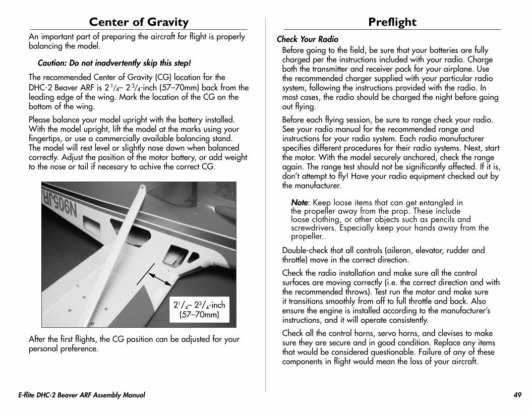
The recommended Center of Gravity (CG) location for the DHC-2 Beaver ARF is 2
1/4– 2 3/4-inch (57–70mm) back from the
leading edge of the wing. Mark the location of the CG on the bottom of the wing.
Please balance your model upright with the battery installed. With the model upright, lift the model at the marks using your fingertips, or use a commercially available balancing stand. The model will rest level or slightly nose down when balanced correctly. Adjust the position of the motor battery, or add weight to the nose or tail if necesary to achive the correct CG.
After the first flights, the CG position can be adjusted for your personal preference.
PreflightCheck Your Radio
Before going to the field, be sure that your batteries are fully charged per the instructions included with your radio. Charge both the transmitter and receiver pack for your airplane. Use the recommended charger supplied with your particular radio system, following the instructions provided with the radio. In most cases, the radio should be charged the night before going out flying.
Before each flying session, be sure to range check your radio. See your radio manual for the recommended range and instructions for your radio system. Each radio manufacturer specifies different procedures for their radio systems. Next, start the motor. With the model securely anchored, check the range again. The range test should not be significantly affected. If it is, don’t attempt to fly! Have your radio equipment checked out by the manufacturer.
Note: Keep loose items that can get entangled in the propeller away from the prop. These include loose clothing, or other objects such as pencils and screwdrivers. Especially keep your hands away from the propeller.
Double-check that all controls (aileron, elevator, rudder and throttle) move in the correct direction.
Check the radio installation and make sure all the control surfaces are moving correctly (i.e. the correct direction and with the recommended throws). Test run the motor and make sure it transitions smoothly from off to full throttle and back. Also ensure the engine is installed according to the manufacturer’s instructions, and it will operate consistently.
Check all the control horns, servo horns, and clevises to make sure they are secure and in good condition. Replace any items that would be considered questionable. Failure of any of these components in flight would mean the loss of your aircraft.

50 E-flite DHC-2 Beaver ARF Assembly Manual
be either landed on the mains or three pointed on the gear in a full stall. The choice is yours. Landing without using flaps is no different, just a bit faster on the final approach, but very manageable.
Flying on floats is another world of fun with the Beaver. We recommend the use of the Power 32 for float flying on 4S for reasons of the extra weight and drag. This is where this model really excels and is why we included the float mounts in the kit. Taxiing out is a slow process and full up elevator should be used to help reduce the water spray from the propeller. Once you have lined up into the wind, apply power slowly with full up elevator being held. As the model accelerates and comes up on step, reduce the amount of up elevator you are holding and allow the model to plane on the step of the floats. Once you are here, apply up elevator in a smooth action until the model breaks free from the water. Continue your climb out as you did from land. If you are using half flaps for takeoff, you will find the Beaver lifts out of the water very easily without any issues at all. Flying is a special treat with the floats on. It is very easy to get caught up in the look of flying through the Alaskan bush as you cross by on a fly-by. Setting up to land is as easy as dropping the flaps to the full position and setting up on final. Manage your power as the floats add a fair amount of drag to the airframe. It is common to be carrying a small bit of power on final with the floats and full flaps. Manage the power to control the descent and elevator to control the airspeed.
As you get closer to the water begin to flair the model and flatten out the approach. The goal is to set the model down on the aft edge of the floats. Once the floats hit the water, the drag will cause the model to slow very quickly. You will want to initially carry the up elevator you had for the flair until the model begins to slow to a point where it will not take flight again. Touch and gos are a graceful maneuver with the Beaver and are a sight to see.
We at E-flite hope you enjoy your Beaver as much as we have. Happy landings!
Flying Your DHC-2 Beaver ARFYou will find the Beaver to be a very docile model in the air and on the ground. Takeoff's are a piece of cake with the large rudder and flaps. Landings are slow and gentle with the large flap area fully deployed on final approach.
Begin by placing the model on the ground. Check all control throws and ensure everything is traveling in the right direction. Move your idle trim up until the prop begins to spin; this will be your flight idle. Taxi into position on the runway, facing into the wind. Do your first takeoff without using the flaps. Apply power slowly and steer with rudder. The tail will come up very quickly. As you apply full throttle and come to speed, apply a slight amount of up elevator and the Beaver should lift off gently and begin to climb upwards. As you climb out release the elevator and maintain a gentle climb to about 100 feet of altitude.
Once at about 100 feet of altitude trim the model for level flight at 5/8 throttle. You will find the Beaver to be very gentle on the control and feel quite light on the sticks. The model is capable of all the basic aerobatic maneuvers; loops, rolls, stall turns, inverted flight, etc.
You will want to fly with the flaps a bit to get use to them. They are very effective in slowing the model down on final approach. When the desired altitude is reached, drop the flaps to the half and then the full position. Check to see if there is any roll trim required. If the model rolls one way or another, retract the flaps. Land the model and adjust the flap linkage. If the model rolls left, the right flap is down too far. If the model rolls right, the left flap is down too far.
If you have no roll issues with the model then you are ready to set up for landing. We normally do a pass over the runway and drop the flaps on this pass. Turn into the downwind and manage the power at about 1/2 throttle. As you turn to base leg, you may reduce the throttle a bit and then when you turn final adjust the power to maintain a shallow descent with the model. As you come down to an altitude of about 8 feet over the runway, begin to level the model out and as you get within 3 feet, you will begin to flare for landing. The Beaver likes to

51E-flite DHC-2 Beaver ARF Assembly Manual
2008 Official AMA National Model Aircraft Safety Code
GENERAL1) I will not fly my model aircraft in sanctioned events, air shows
or model flying demonstrations until it has been proven to be airworthy by having been previously, successfully flight tested.
2) I will not fly my model higher than approximately 400 feet within 3 miles of an airport without notifying the airport operator. I will give right-of-way and avoid flying in the proximity of full-scale aircraft. Where necessary, an observer shall be utilized to supervise flying to avoid having models fly in the proximity of full-scale aircraft.
3) Where established, I will abide by the safety rules for the flying site I use, and I will not willfully or deliberately fly my models in a careless, reckless and/or dangerous manner.
4) The maximum takeoff weight of a model is 55 pounds, except models flown under Experimental Aircraft rules.
5) I will not fly my model unless it is identified with my name and address or AMA number on or in the model. (This does not apply to models while being flown indoors.)
6) I will not operate models with metal-bladed propellers or with gaseous boosts, in which gases other than air enter their internal combustion engine(s); nor will I operate models with extremely hazardous fuels such as those containing tetranitromethane or hydrazine.
RADIO CONTROL1) I will have completed a successful radio equipment ground range
check before the first flight of a new or repaired model.2) I will not fly my model aircraft in the presence of spectators until I
become a qualified flier, unless assisted by an experienced helper.3) At all flying sites a straight or curved line(s) must be established
in front of which all flying takes place with the other side for spectators. Only personnel involved with flying the aircraft are allowed at or in front of the flight line. Intentional flying behind the flight line is prohibited.
4) I will operate my model using only radio control frequencies currently allowed by the Federal Communications Commission. (Only properly licensed Amateurs are authorized to operate equipment on Amateur Band frequencies.)
5) Flying sites separated by three miles or more are considered safe from site-to-site interference, even when both sites use the same frequencies. Any circumstances under three miles separation require a frequency management arrangement, which may be either an allocation of specific frequencies for each site or testing to determine that freedom from interference exists. Allocation plans or interference test reports shall be signed by the parties involved and provided to AMA Headquarters.
Documents of agreement and reports may exist between (1) two or more AMA Chartered Clubs, (2) AMA clubs and individual AMA members not associated with AMA Clubs, or (3) two or more individual AMA members.
6) For Combat, distance between combat engagement line and spectator line will be 500 feet per cubic inch of engine displacement. (Example: .40 engine = 200 feet.); electric motors will be based on equivalent combustion engine size. Additional safety requirements will be per the RC Combat section of the current Competition Regulations.
7) At air shows or model flying demonstrations, a single straight line must be established, one side of which is for flying, with the other side for spectators.
8) With the exception of events flown under AMA Competition rules, after launch, except for pilots or helpers being used, no powered model may be flown closer than 25 feet to any person.
9) Under no circumstances may a pilot or other person touch a powered model in flight.

12403.1
© 2008 Horizon Hobby, Inc. 4105 Fieldstone Road
Champaign, Illinois 61822 (877) 504-0233 horizonhobby.com
E-fliteRC.com