DHANALAKSHMI SRINIVASAN ENGINEERING COLLEGE … COMMUNICATION ENGINEERING... · 2018-12-12 ·...
66
DHANALAKSHMI SRINIVASAN ENGINEERING COLLEGE DEPARTMENT OF EEE EC6651 – COMMUNICATION ENGINEERING TWO MARK QUESTIONS WITH ANSWERS UNIT I ANALOG COMMUNICATION 1. Define Modulation and Amplitude Modulation. Modulation is the process of varying one or more properties of a periodic waveform, called the carrier signal, with a modulating signal which typically contains information to be transmitted. Amplitude Modulation is the process of changing the amplitude of a relatively high frequency carrier signal in proportion with the instantaneous value of the modulating signal . 2. Define Modulation index.[Nov-Dec 2016] Modulation index is a term used to describe the amount of amplitude change present in an AM waveform .It is also called as coefficient of modulation. Mathematically modulation index is m = Em / Ec Where m = Modulation coefficient Em = Peak change in the amplitude of the output waveform voltage. Ec= Peak amplitude of the un-modulated carrier voltage. 3. Define Percentage modulation for an AM wave. Percent modulation gives the percentage change in the amplitude of the output wave when the carrier is acted on by a modulating signal. 4. What is the need for modulation? (AU April-May 09 & 11) (May/June 2016) Base band transmission has many limitations which can be overcome by using modulation, since modulation shifts low frequency to high and reduce the size of the antenna, avoid mixing of signals, increase the range and quality of communication 5. Define Low level Modulation. In low level modulation, modulation takes place prior to the output element of the final stage of the transmitter. For low level AM class A amplifier is used. 6. Define High level Modulation. In high level modulators, the modulation takes place in the final element of the final stage where the carrier signal is at its maximum amplitude. For high level modulator class C amplifier is used. 7. What is the advantage of low level modulation? An advantage of low level modulation is that less modulating signal power is required to achieve a high percentage of modulation.
Transcript of DHANALAKSHMI SRINIVASAN ENGINEERING COLLEGE … COMMUNICATION ENGINEERING... · 2018-12-12 ·...

DHANALAKSHMI SRINIVASAN ENGINEERING COLLEGE
DEPARTMENT OF EEE
EC6651 – COMMUNICATION ENGINEERING
TWO MARK QUESTIONS WITH ANSWERS
UNIT IANALOG COMMUNICATION
1. Define Modulation and Amplitude Modulation.
Modulation is the process of varying one or more properties of a periodic waveform, called thecarrier signal, with a modulating signal which typically contains information to be transmitted.Amplitude Modulation is the process of changing the amplitude of a relatively high frequencycarrier signal in proportion with the instantaneous value of the modulating signal.
2. Define Modulation index.[Nov-Dec 2016]Modulation index is a term used to describe the amount of amplitude change present in an AMwaveform .It is also called as coefficient of modulation. Mathematically modulation index is m = Em / EcWhere m = Modulation coefficientEm = Peak change in the amplitude of the output waveform voltage. Ec= Peak amplitude of the un-modulated carrier voltage.
3. Define Percentage modulation for an AM wave.Percent modulation gives the percentage change in the amplitude of the output wave when
the carrier is acted on by a modulating signal.
4. What is the need for modulation? (AU April-May 09 & 11) (May/June 2016)
Base band transmission has many limitations which can be overcome by using modulation,since modulation shifts low frequency to high and reduce the size of the antenna, avoid mixingof signals, increase the range and quality of communication
5. Define Low level Modulation.In low level modulation, modulation takes place prior to the output element of the final
stage of the transmitter. For low level AM class A amplifier is used.
6. Define High level Modulation.In high level modulators, the modulation takes place in the final element of the final stage
where the carrier signal is at its maximum amplitude. For high level modulator class C amplifieris used.
7. What is the advantage of low level modulation? An advantage of low level modulation is that less modulating signal power is required to achieve a high percentage of modulation.

8. Distinguish between low level and high level modulation.
S.No Low level modulation High level modulation1 Modulation takes place in prior to the output Modulation takes place in the
of the final stage of the Transmitter final stage where carrier signal is atmaximum amplitude.
2 It requires less power to achieve a high It requires much higher amplitude ofentage of modulation. modulating signal to achieve a reasonable
percent modulation
9. Define image frequency.An image frequency is any frequency other than the selected radio frequency carrier that, if
allowed to enter a receiver and mix with the local oscillator, will produce a cross product frequency that is equal to the intermediate frequency.
10. State the advantages of FM over AM. (AU Nov-Dec 09)Frequency modulation is one type of angle modulation this has the advantages over
amplitude modulation such as Noise reduction, improved system fidelity and more efficient use of power.
11. Define standing wave ratio. (AU Nov-Dec 09)Standing wave the is ratio between the reflected wave and normal wave components
voltage/current at any point is known as SWR, the plot of resultant voltage or current along the linelength is termed as standing waves.
12. Define Local Oscillator tracking.Tracking is the ability of the local oscillator in a receiver to oscillate either above or below
the selected radio frequency carrier by an amount equal to the intermediate frequency throughout the entire radio frequency band.
13. Define High side injection tracking.In high side injection tracking, the local oscillator should track above the incoming RF carrier
by a fixed frequency equal to fRF +fIF.
14. Define Low side injection tracking.In low side injection tracking, the local oscillator should track below the RF carrier by a fixed
frequency equal to fRF -fIF.
15. Define tracking error. How it is reduced.The difference between the actual local oscillator frequency and the desired frequency
is called tracking error. It is reduced by a technique called three point tracking.
16. Define Heterodyning.Heterodyne means to mix two frequencies together in a nonlinear device or to translate one
frequency to another using nonlinear mixing.

17. What is super heterodyne receiver? (AU April-May 09 & 11)Heterodyne means to mix two frequencies together in a nonlinear device or to translate
one frequency to another using nonlinear mixing.There are five sections to a super heterodyne receiver: that are RF section,
Mixer/converter section, IF section, Audio detector section, and Amplifier section.
18. What are the advantages of the super heterodyne receiver? (AU April-May09)Advantages in SH Receiver over TRF receivers are Improved the selectivity in terms of
adjacent channels, more uniform selectivity over frequency range, improved in receiver stability,higher gain per stage and uniform bandwidth.
19. Explain the disadvantages of conventional/double side band full carrier system.In conventional AM, carrier power constitutes two thirds or more of the total transmitted
power. This is a major drawback is the carrier contains no information; the sidebands contain theinformation.
Second, conventional AM systems utilize twice as much bandwidth as needed with single sideband systems.
20. Define Single sideband suppressed carrier AM. [April/May 2017]AM Single sideband suppressed carrier is a form of amplitude modulation in which the
carrier is totally suppressed and one of the sidebands removed.
21. Define AM Vestigial sideband. [April/May 2017]AM vestigial sideband is a form of amplitude modulation in which the carrier and one
complete sideband are transmitted, but only part of the second sideband is transmitted.
22. What are the advantages and disadvantages of single side band transmission? [May/June 2016]Advantages
1. The bandwidth requirement of the single sideband system is half than required by double sideband system.
2. Since SSB system utilizes half the bandwidth than DSB, the thermal noise power is reduced to half that of DSB system.
3. The full carrier DSB wave has poor efficiency since the major transmitted power is concentrated in the carrier which contains no information. Thus the total power in SSB is less than the total power in DSB. % power saving in SSB is 83.33%.
4. In the spectrum of AM wave, both the sidebands carry same amount of information which makes it meaningless to transmit same information in both the sidebands thus leading to power wastage. This is overcome in the SSB technique by suppressing undesired sideband.
Disadvantages1. The generation of SSB is quite complex as the suppression of one of the sidebands is
difficult.2. The generation of SSB requires sharp cut off characteristics of the sideband suppression
filter.3. SSB receivers require more precise tuning than DSB4. SSB receivers require carrier recovery and synchronization circuit which adds to their
cost, complexity and size.

24. Define pulse code modulation.In pulse code modulation, analog signal is sampled and converted to fix length, serial
binary number for transmission. The binary number varies according to the amplitude of theanalog signal.
25. Define direct frequency modulation.In direct frequency modulation, frequency of a constant amplitude carrier signal is directly
proportional to the amplitude of the modulating signal at a rate equal to the frequency of the modulating signal.
26. Define indirect frequency Modulation.In indirect frequency modulation, phase of a constant amplitude carrier directly proportional
to the amplitude of the modulating signal at a rate equal to the frequency of the modulating signal.
27. Define critical frequency. (AU Nov-Dec 09)Critical frequency is the maximum frequency that the radio wave can be transmitted
vertically and still some of the frequency will be refracted back to the transmitter.
28. Define instantaneous frequency deviation.The instantaneous frequency deviation is the instantaneous change in the frequency of the
carrier and is defined as the first derivative of the instantaneous phase deviation.
29. A carrier signal with power of 40Watts is amplitude modulated by a sinusoidal signal.Find the power of the modulated signal if the modulation index is 0.7.Solution: (AU Nov-Dec 09)
Carrier power Pc= 40 Watts and m=0.7Modulated power is P Total =Pc(1+(m)2/2) = 49.8Watts
30. Define frequency deviation.Frequency deviation is the change in frequency that occurs in the carrier when it is acted on
by a modulating signal frequency. Frequency deviation is typically given as a peak frequencyshift in Hertz (∆f).The peak to peak frequency deviation (2∆f) is sometimes called carrierswing. The peak frequency deviation is simply the product of the deviation sensitivity and thepeak modulating signal voltage and is expressed mathematically as ∆f=K1 x Vm Hz.
31. Differentiate NBFM and WBFM [Nov-Dec 2016]
WIDEBAND FM:Parameters :1. modulation index : Greater than 12. maximum deviation: 75 kHz3. range of modulating frequency: 30 Hz to 15 kHz4. maximum modulation index: 5 to 25005. bandwidth : large,about 15 times higher than BW of narrowband FM6. applications : entertainment broadcasting7. pre-emphasis and de-emphasis : is needed.
NARROWBAND FM:parameters :1.modulation index: less than or slightly greater than 12. maximum deviation: 5kHz3. range of modulating frequency : 30 Hz to 3 kHz4. maximum modulation index : slightly greater than 1 5. bandwidth : small.approximately same as that of AM6. applications: FM mobile communication like police wireless,ambulance etc7. pre-emphasis and de-emphasis : is needed.

32. Define narrow band FM. [April/May 2017]Narrowband FM is used for voice communications in commercial and amateur radio settings.In broadcast services, where audio fidelity is important, wideband FM is generally used. In two-way radio, narrowband FM (NBFM) is used to conserve bandwidth for land mobile, marinemobile and other radio services.
UNIT IIDIGITAL COMMUNICATION
1. State Shannon’s fundamental theorem of information capacity.The information capacity of a communication system represents the
number of independent symbols that can be carried through that system in a given unit of time.
It is expressed in bits per secThe information capacity of Gaussian channel is given
by I=B log2 (1+S/N) bpsBchannelBandwidth Ssignal powerNnoise within the channel.
2. Define bit rate and baud rate.Bit rate refers to the rate of change of a digital information signal which is usually
binary. Unit is bps Baud rate is also a rate of change, it refers to the rate of change of a signal on the transmission medium after encoding and modulation. Unit is baud
3. Write the advantages of BPSK.i) BPSK has a Bandwidth which is lower than that of a BFSK signal.ii) BPSK has the best performance of all the systems in presence of noise.iii) It gives the minimum possibility of error.iv) BPSK has very good noise immunity.
4. Compare Bandwidth efficiency of BPSK and QPSK modulated signals.
Bandwidth of BPSK =fb
Bandwidth of QPSK = fb/2Where fb is the input data rate
5. What is digital transmission?Transmission of digital signals between two or more points in a
communication system. The original information can be of analog or digital. If it is analog then it is converted to digital.
6. List the effects of ‘M’ in M-ary digital modulation technique.M-ary encoding system able to transmit information at a rate that is log 2M faster than
the binary PAM system for a fixed channel bandwidth. M-ary system requires moretransmitted power.
7. What is meant by non-coherent digital modulation technique?Non-coherent digital modulation technique is the system in which a synchronous
carrier is not used.

8. What is meant by carrier recovery?Carrier is the process of extracting a phase coherent reference carrier from a
received signal.It is also called as phase referencing.
9. What are the types of carrier recovery? Two types of carrier recovery circuits are
i) Squaring loopii) Costas loop
10. What is meant by offset QPSK?
Offset QPSK is the modified form of QPSK, where the bit waveforms on the I
channel and Q channels are shifted in phase from each other by one-half of a bit time.
11.Calculate the capacity of a standard 4 KHz telephone channel with a 30 dBsignal to noise ratio?
Given:B =4 KHz
S/N =30dB Soln:
I=3.32B log10 (1+S/N)3
=3.32(4x10 ) log103
(1+1000) =39.84x10=39.84Kbps
12. Difference between BPSK and QPSKParameters BPSK QPSK
Variable Characteristics of Phase Phasethe CarrierType of Modulation Two Level Four LevelBit Rate / Baud Rate Bit Rate = Baud Rate Bit Rate = 2 Baud RateComplexity Complex Very ComplexApplications Suitable for applications Suitable for applications
that needs high bit rate that needs very high bit rate
13. Compare QAM and QPSK.Parameter QPSK QAM
Type Of Modulation Quadrature Phase Modulation Quadrature AmplitudeModulation
Noise Immunity Better than ASK Poorer than QPSKSystem Complexity Less Complex than ASK More Complex than QPSKType of Modulation Synchronous Synchronous

14 .Comparison of Digital Modulation Systems [May/June 2016]
Parameter Binary ASK Binary FSK Binary PSKVariable Amplitude Frequency PhaseCharacteristicsNoise Immunity Low Low highPerformance in Poor Better than ASK Better than FSKpresence of noiseComplexity Simple Moderately Very Complex
ComplexBit Rate Suitable upto 100 Upto about 1200 Suitable for high bit
Bps bps Rate
15. Why QPSK is better than PSK. QPSK is better than PSK
• Due to multilevel modulation used in QPSK, it is possible to increase the bit rate to double the bit rate of PSK without increasing the Bandwidth
• The noise immunity of QPSK is same as that of PSK system• Available channel bandwidth is utilized in a better way by the QPSK system
than PSK system.
16. Define ASK.In Amplitude Shift Keying the amplitude of the carrier is varied in
proportional with the amplitude of the message signal. Here the message signal isdigital and carrier is analog.
17. Define PAM.The amplitude of a constant width, constant position is varied in proportion
with the instantaneous magnitude of the modulating signal.
28. Define PWM.The width of carrier pulse is made to vary in proportion with
the instantaneous magnitude of the modulating signal.
19. Define PPM.The amplitude and width of the pulse is kept constant but the position of
each pulse is varied in accordance with the amplitudes of the sampled values of the modulating signal.
20. Define PTM.Modulation of the time intervals between successive pulses of constant duration
and amplitude in accordance with a signal; specify a system of multiplex high-frequency transmission using this method of modulation.

21. Define PCM.Method used to digitally represent sampled analog signals. It is the standard form
of digital audio in computers, Compact Discs, digital telephony and other digital audio applications. In a PCM stream, the amplitude of the analog signal is sampled regularly at uniform intervals, and each sample is quantized to the nearest value within a range of digital steps.
22. Define DM.Delta modulation (DM or -modulation) is an analog-to-digital and digital-to-
analog signal conversion technique used for transmission of voice information wherequality is not of primary importance. DM is the simplest form of differential pulse-code modulation (DPCM) where the difference between successive samples isencoded into n-bit data streams.
23. Define sampling theorem and aliasing. [May/June 2016] [April/May2017] Sampling theoremIt states that to convert a continuous time signal to discrete time signal, sampling frequency mustbe greater than or equal to twice of highest modulating frequency so that successful Reconstruction is possible.
Aliasing
In signal processing and related disciplines, aliasing is an effect that causes different signals tobecome indistinguishable (or aliases of one another) when sampled. It also refers to the distortionor artifact that results when the signal reconstructed from samples is different from the originalcontinuous signal.
24. State any two advantages of MSK. [April/May 2017]
MSK and BFSK produce constant envelope carrier signals with no amplitude variations.
This is a desirable characteristic for improving the power efficiency of transmitters.
UNIT IIISOURCE CODES, LINE CODES AND ERROR CONTROL
1. Define Shannon Entropy.Shannon entropy, which quantifies the expected value of the
information contained in a message. Entropy is typically measured in bits, nats, or bans. Shannon entropy is the average unpredictability in a random variable, which is equivalent to its information content.
2. Define Shannon source coding theorem.Shannon's source coding theorem (or noiseless coding theorem) establishes
the limits to possible data compression, and the operational meaning of the Shannon entropy.
3. Define Shannon limit.The Shannon limit or Shannon capacity of a communications channel is the
theoretical maximum information transfer rate of the channel, for a particular noise level.
4. Define Huffman coding.Huffman coding is an entropy encoding algorithm used for lossless data
compression. The term refers to the use of a variable-length code table for encoding a source symbol (such as a character in a file) where the variable-length code table has been derived in a particular way based on the estimated probability of occurrence for each possible value of the source symbol.
5. What are the uses of Modified Huffman coding.Modified Huffman coding is used in fax machines to encode black on
white images (bitmaps). It combines the variable length codes of Huffman coding with the coding of repetitive data in run-length encoding.
6. Define SNR.Ratio of signal power to the noise power, often expressed in decibels.
A ratio higher than 1:1 (greater than 0 dB) indicates more signal than noise.
7. Define NRZ.Non-return-to-zero (NRZ) line code is a binary code in which 1s are
represented by one significant condition (usually a positive voltage) and 0s are represented by some other significant condition (usually a negative voltage), with no other neutral or rest condition.
8. Define RZ.Return-to-zero (RZ) describes a line code used in telecommunication signals
in which the signal drops (returns) to zero between each pulse. This takes place even if a number of consecutive 0's or 1's occur in the signal. The signal is self-clocking.

9. Define Error control coding. [April/May 2017]Error control coding aims at developing methods for coding to
check the correctness of the bit stream transmitted. The bit stream representation of a symbol is called the codeword of that symbol.
10. Mention the types of error control. Linear Block Codes Repetition Codes Convolution Codes
11. Define linear block codes.A code is linear if two codes are added using modulo-2 arithmetic produces a
third codeword in the code. Consider a (n, k) linear block code. Here,1. n represents the codeword length2. k is the number of message bit3. n − k bits are error control bits or parity check bits
generated from message using an appropriate rule.
12. Define Repetition Codes.This is the simplest of linear block codes. Here, a single message bit is encoded
into a block of n identical bits, producing an (n, 1) block code. This code allows variable amount of redundancy. It has only two codewords - all-zero codeword and all-one codeword.
13. Define convolution Codes.
A convolution code is a type of error-correcting code in which
• Each m-bit information symbol (each m-bit string) to be encoded is transformed into an n-bit symbol, where m/n is the code rate (n ≥ m) and
• The transformation is a function of the last k information symbols, where k is the constraint length of the code.
14. Define Block Codes.Block codes comprise the large and important family of error-correcting codes
that encode data in blocks. Block Codes are conceptually useful. They allow coding theorists,mathematicians, and computer scientists to study the limitations of all block codes in a unified way. Such limitations often take the form of bounds that relate differentparameters of the block code to each other, such as its rate and its ability to detect andcorrect errors.
15. Define Modified AMI Codes.Modified AMI codes are Alternate Mark Inversion (AMI) line codes in which
bipolar violations may be deliberately inserted to maintain system synchronization. There areseveral types of modified AMI codes, used in various T-carrier and E-carrier systems.16. Define Shannon–Fano coding.In Shannon–Fano coding, the symbols are arranged in order from most probable to least probable, and then divided into two sets whose total probabilities are as close as possible to being equal. All symbols then have the first digits of their codes assigned; symbols in the first set receive "0" and symbols in the second set receive "1".

17. Define source coding. State the significance of source coding. [May/June 2016]A line code (also called digital baseband modulation or digital baseband transmission method) isa code chosen for use within a communications system for baseband transmission purposes. Line coding is often used for digital data transport.
SignificanceIn information theory, Shannon's source coding theorem (or noiseless coding theorem)establishes the limits to possible data compression, and the operational meaning of the Shannonentropy. However it is possible to get the code rate arbitrarily close to the Shannon entropy, withnegligible probability of loss.
UNIT IVMULTIPLE ACCESS TECHNIQUES
1. Define spread spectrum.Spread-spectrum techniques are methods by which a signal (e.g. an electrical,
electromagnetic, or acoustic signal) generated with a particular bandwidth is deliberatelyspread in the frequency domain, resulting in a signal with a wider bandwidth.
2. Mention the uses of spread spectrum.Used for a variety of reasons, including the establishment of secure
communications, increasing resistance to natural interference, noise and jamming,to prevent detection, and to limit power flux density (e.g. in satellite downlinks).
3. Define multiple access.Multiple access defined as a means of allowing multiple users to simultaneously
share the finite bandwidth with least possible degradation in the performance of the system.
4. Mention the types of multiple access.1. Frequency Division Multiple Access (FDMA)2. Time Division Multiple Access (TDMA)3. Code Division Multiple Access (CDMA)4. Space Division Multiple Access (SDMA)
5. Define Frequency Division Multiple Access (FDMA).In FDMA, each user is allocated a unique frequency band or channel.
During the period of the call, no other user can share the same frequency band.
6. Define Time Division Multiple Access (TDMA).TDMA systems divide the channel time into frames. Each frame is further partitioned
into time slots. In each slot only one user is allowed to either transmit or receive.
7. Mention the features of FDMA. Continuous transmission Narrow bandwidth Low ISI Low overheadSimple hardware at mobile unit and BS Use of duplexer

8. Mention the features of TDMA. [April/May 2017] Multiple channels per carrier or RF channels. Burst transmission since channels are used on a timesharing basis. Transmitter can
be turned off during idle periods.
Narrow or wide bandwidth – depends on factors such as modulation scheme, number of voice channels per carrier channel.
High ISI – Higher transmission symbol rate, hence resulting in high ISI. Adaptive equalizer required.
9. Define CDMA. [April/May 2017]
CDMA is also called DSSS (Direct Sequence Spread Spectrum).In CDMA, the narrowband message signal is multiplied by a very largebandwidth signal called spreading signal (code) before modulation andtransmission over the air. This is called spreading.
10. List the Spreading signal elements. Has Chip period and and hence, chip rate Spreading signal use a pseudo-noise (PN) sequence (a pseudo-
random sequence) PN sequence is called a codeword Each user has its own cordword Codewords are orthogonal. (low autocorrelation) Chip rate is oder of magnitude larger than the symbol rate.
11. Mention the advantages of CDMA.
Random access possible Users can start their transmission at any time
Cell capacity is not concerete fixed like in TDMA or FDMA systems. Has soft capacity
Higher capacity than TDMA and FDMA No frequency management No equalizers needed No guard time needed Enables soft handoff .
12. Define SDMA.Space-division multiple access (SDMA) is a channel access method based on creating parallel spatial pipes next to higher capacity pipes through spatial multiplexing and/or diversity, by which it is able to offer superior performance in radiomultiple access communication systems.
13. Define pseudo noise sequence. [May/June 2016]In cryptography, pseudorandom noise (PRN) is a signal similar to noise which satisfies one ormore of the standard tests for statistical randomness. Although it seems to lack any definitepattern, pseudorandom noise consists of a deterministic sequence of pulses that will repeatitself after its period.14. Define near-far problem in CDMA. [May/June 2016]
The near–far problem or hearability problem is a situation that is common in wirelesscommunication systems, in particular, CDMA. In some signal jamming techniques, the near–farproblem is exploited to disrupt communications.

UNIT VSATELLITE, OPTICAL FIBER – POWERLINE, SCADA
1. Define satellite.Satellite is a celestial body that orbits around a planet. In aerospace terms, a satellite is a
space vehicle launched by humans and orbits earth or another celestial body.
2. State Kepler’s first law.Kepler’s first law states that a satellite will orbit a primary body following an elliptical path.
3. State Kepler’s second law.Kepler’s second law states that for equal time intervals of time a satellite will sweep out equal
areas in the orbital plane, focused at the bary center.
4. State Kepler’s third law.The third law states that the square of the periodic time of orbit is proportional to the cube of
the mean distance between the primary and the satellite.
5. Define orbital satellite.Orbital satellites are also called as Asynchronous satellite. Asynchronous satellites rotate
around earth in an elliptical or circular pattern. In a circular orbit, the speed or rotation is constant however in elliptical orbits the speed depends on the height the satellite is above the earth.
6. Define protrude orbit. (AU April-May 09)
If the satellite is orbiting in the same direction as earth’s rotation and at an angular velocity greater than that of earth, the orbit is called a prograde (or) posigrade orbit.
7. Define retrograde orbit? (AU April-May 09)If the satellite is orbiting in the opposite direction as the earth’s rotation or in the same
direction with an angular velocity less than that of earth, the orbit is called a retrograde orbit.
8. Define Geo synchronous satellite? (AU Nov-Dec 09)Geo synchronous or geo stationary satellites are those that orbit in a circular pattern with
an angular velocity equal to that of Erath. Geosynchronous satellites have an orbital time of approximately 24 hours, the same as earth; thus geosynchronous satellites appear to be stationary as they remain in a fixed position in respect to a given point on earth.
9. Define apogee and perigee?The point in an orbit which is located farthest from the earth is called apogee.
The point in an orbit which is located closest to earth is called perigee.
10. Define angle of inclination?The angle of inclination is the angle between the earth’s equatorial plane and the
orbital plane of a satellite measured counterclockwise at the point in the orbit where itcrosses the equatorial plane traveling from south to north.

11. Define Descending node?The point where the polar or inclined orbit, crosses the equatorial plane, traveling from south
to north. This point is called descending node.
12. Define ascending node.The point where a polar or inclined orbit crosses the equatorial plane traveling fromnorth to south is called ascending node.
13. Define line of nodes.The line joining the ascending and descending nodes through the center of earth is called line of nodes.
14. Define angle of elevation.Angle of elevation is the vertical angle formed between the direction of travel of an
electromagnetic wave radiated from an earth station antenna pointing directly toward asatellite and the horizontal plane.
15. Define Azimuth angle.Azimuth is the horizontal angular distance from a reference direction, either the southern or northern most point of the horizon.
16. What are the advantages of optical fiber communication?Greater information capacity
Immunity to crosstalk
Immunity to static interference Environmental immunity Safety
Security
17. Define a fiber optic system.An optical communications system is an electronic communication system that useslight as the carrier of information. Optical fiber communication systems use glass orplastic fibers to contain light waves and guide them in a manner similar to the way
electromagnetic waves are guided through a waveguide.
18. Define refractive index.The refractive index is defined as the as the ratio of the velocity of propagation of light ray in free space to the velocity of propagation of a light ray in a given material.
Mathematically, the refractive index is n = c/υWhere c = speed of light in free space, υ = speed of light in a given material
19. Define critical angle. (AU April-May09)Critical angle is defined as the minimum angle of incidence at which a light raymay strike the interface of two media and result in an angle of refraction of 90°or greater.
20. Define single mode and multi mode propagation.If there is only one path for light to take down the cable, it is called single mode.
21. Define acceptance angle.
It defines the maximum angle in which external light rays may strike the air/fiber interface and still propagate down the fiber with a response that is no greater than 10 dB below the maximum value.
22. Define numerical aperture. (AU April- May11)Numerical aperture is mathematically defined as the sine of the maximum angle a
light ray entering the fiber can have in respect to the axis of the fiber and still propagatedown the cable by internal reflection.
23. Define modal dispersion.Modal dispersion or pulse spreading is A Used by the difference in the propagation times of light rays that take different paths down a fiber. Modal dispersion can occur only in multimode fibers. It can be reduced by using single mode step index fibers and graded index fibers.
24. What are the advantages of hetero junction LEDs?a. The increase in current density generates a more brilliant light spot.b. The smaller emitting area makes it easier to couple its emitted light into fiber.c. The small effective area has a smaller capacitance, which allows the planar heterojunction LED to be used at higher speeds.
25. What are the disadvantages of injection laser diode?ILDs are typically on the order of 10 times more expensive than LEDs
Use ILDs operate at higher powers, they typically have a much shorter life time than LEDs.
ILDs are more temperature dependent than LEDs.
26. What are the different types of satellites? [May/June 2016] Low Earth Orbits. Sun-Synchronous orbits. Geosynchronous satellites. Geostationary satellites.
27. What are the different types of fiber? Which is more preferred? [April/may 2017] There are three types of fiber optic cable commonly used: single mode, multimode and plastic optical fiber (POF). Transparent glass or plastic fibers which allow light to be guided from one end to the other with minimal loss. So it is mostly preferred.
DHANALAKSHMI SRINIVASAN ENGINNERING COLLEGE
DEPARTMENT OF EEE
EC6651-COMMUNICATION ENGINEERING
16 MARK QUESTIONS WITH ANSWERS
UNIT-I
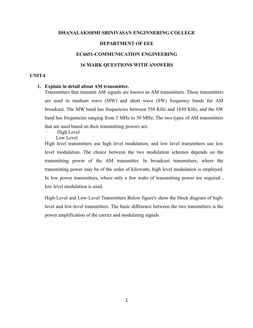
1. Explain in detail about AM transmitter.Transmitters that transmit AM signals are known as AM transmitters. These transmitters
are used in medium wave (MW) and short wave (SW) frequency bands for AM
broadcast. The MW band has frequencies between 550 KHz and 1650 KHz, and the SW
band has frequencies ranging from 3 MHz to 30 MHz. The two types of AM transmitters
that are used based on their transmitting powers are: · High Level· Low LevelHigh level transmitters use high level modulation, and low level transmitters use low
level modulation. The choice between the two modulation schemes depends on the
transmitting power of the AM transmitter. In broadcast transmitters, where the
transmitting power may be of the order of kilowatts, high level modulation is employed.
In low power transmitters, where only a few watts of transmitting power are required ,
low level modulation is used. High-Level and Low-Level Transmitters Below figure's show the block diagram of high-
level and low-level transmitters. The basic difference between the two transmitters is the
power amplification of the carrier and modulating signals
1

Figure is drawn for audio transmission. In high-level transmission, the powers of the carrier and
modulating signals are amplified before applying them to the modulator stage, as shown in
figure. In low-level modulation, the powers of the two input signals of the modulator stage are
not amplified. The required transmitting power is obtained from the last stage of the transmitter,
the class C power amplifier.
The various sections of the figure are:
· Carrier oscillator
· Buffer amplifier
· Frequency multiplier
· Power amplifier
· Audio chain
· Modulated class C power amplifier
ü Carrier oscillator
2

The carrier oscillator generates the carrier signal, which lies in the RF range. The frequency of
the carrier is always very high. Because it is very difficult to generate high frequencies with good
frequency stability, the carrier oscillator generates a sub multiple with the required carrier
frequency. This sub multiple frequency is multiplied by the frequency multiplier stage to get the
required carrier frequency. Further, a crystal oscillator can be used in this stage to generate a low
frequency carrier with the best frequency stability. The frequency multiplier stage then increases
the frequency of the carrier to its requirements.
ü Buffer Amplifier
The purpose of the buffer amplifier is twofold. It first matches the output impedance of the
carrier oscillator with the input impedance of the frequency multiplier, the next stage of the
carrier oscillator. It then isolates the carrier oscillator and frequency multiplier.
This is required so that the multiplier does not draw a large current from the carrier oscillator. If
this occurs, the frequency of the carrier oscillator will not remain stable.
ü Frequency Multiplier
The sub-multiple frequency of the carrier signal, generated by the carrier oscillator , is now
applied to the frequency multiplier through the buffer amplifier. This stage is also known as
harmonic generator. The frequency multiplier generates higher harmonics of carrier oscillator
frequency. The frequency multiplier is a tuned circuit that can be tuned to the requisite carrier
frequency that is to be transmitted.
ü Power Amplifier
The power of the carrier signal is then amplified in the power amplifier stage. This is the basic
requirement of a high-level transmitter. A class C power amplifier gives high power current
pulses of the carrier signal at its output.
ü Audio Chain
3

The audio signal to be transmitted is obtained from the microphone, as shown in figure (a). The
audio driver amplifier amplifies the voltage of this signal. This amplification is necessary to
drive the audio power amplifier. Next, a class A or a class B power amplifier amplifies the power
of the audio signal.
ü Modulated Class C Amplifier
This is the output stage of the transmitter. The modulating audio signal and the carrier signal,
after power amplification, are applied to this modulating stage. The modulation takes place at
this stage. The class C amplifier also amplifies the power of the AM signal to the reacquired
transmitting power. This signal is finally passed to the antenna., which radiates the signal into
space of transmission.
The low-level AM transmitter shown in the figure (b) is similar to a high-level transmitter,
except that the powers of the carrier and audio signals are not amplified. These two signals are
directly applied to the modulated class C power amplifier.
4

Modulation takes place at the stage, and the power of the modulated signal is amplified to the
required transmitting power level. The transmitting antenna then transmits the signal.
ü Coupling of Output Stage and Antenna
The output stage of the modulated class C power amplifier feeds the signal to the transmitting
antenna. To transfer maximum power from the output stage to the antenna it is necessary that the
impedance of the two sections match. For this, a matching network is required. The matching
between the two should be perfect at all transmitting frequencies. As the matching is required at
different frequencies, inductors and capacitors offering different impedance at different
frequencies are used in the matching networks.
2. Explain in detail about AM generation.Amplitude Modulation:
Amplitude modulation (AM) is a technique used in electronic communication, most
commonly for transmitting information via a radio carrier wave. AM works by varying
the strength of the transmitted signal in relation to the information being sent. For
example, changes in the signal strength can be used to specify the sounds to be
reproduced by a loudspeaker, or the light intensity of television pixels. (Contrast this with
frequency modulation, also commonly used for sound transmissions, in which the
frequency is varied; and phase modulation, often used in remote controls, in which the
phase is varied).
In order that a radio signal can carry audio or other information for broadcasting or for
two way radio communication, it must be modulated or changed in some way. Although
there are a number of ways in which a radio signal may be modulated, one of the easiest,
and one of the first methods to be used was to change its amplitude in line with variations
of the sound.The basic concept surrounding what is amplitude modulation, AM, is quite
straightforward. The amplitude of the signal is changed in line with the instantaneous
intensity of the sound. In this way the radio frequency signal has a representation of the
5

sound wave superimposed in it. In view of the way the basic signal "carries" the sound or
modulation, the radio frequency signal is often termed the "carrier".
When a carrier is modulated in any way, further signals are created that carry the actual
modulation information. It is found that when a carrier is amplitude modulated, further signals
are generated above and below the main carrier. To see how this happens, take the example of a
carrier on a frequency of 1 MHz which is modulated by a steady tone of 1 kHz.
The process of modulating a carrier is exactly the same as mixing two signals together, and as a
result both sum and difference frequencies are produced. Therefore when a tone of 1 kHz is
mixed with a carrier of 1 MHz, a "sum" frequency is produced at 1 MHz + 1 kHz, and a
difference frequency is produced at 1 MHz - 1 kHz, i.e. 1 kHz above and below the carrier.
If the steady state tones are replaced with audio like that encountered with speech of music, these
comprise many different frequencies and an audio spectrum with frequencies over a band of
frequencies is seen. When modulated onto the carrier, these spectra are seen above and below the
carrier.
6

It can be seen that if the top frequency that is modulated onto the carrier is 6 kHz, then the top
spectra will extend to 6 kHz above and below the signal. In other words the bandwidth occupied
by the AM signal is twice the maximum frequency of the signal that is used to modulated the
carrier, i.e. it is twice the bandwidth of the audio signal to be carried.
In Amplitude Modulation or AM, the carrier signal is given by
It has an amplitude of ‘A’
modulated in proportion to the message bearing (lower frequency) signal
to give
The magnitude of m(t) is chosen to be less than or equal to 1, from reasons having to do withdemodulation, i.e. recovery of the signal from the received signal. The modulation index is thendefined to be
The frequency of the modulating signal is chosen to be much smaller than that of the carriersignal. Try to think of what would happen if the modulating index were bigger than 1.
Fig.3. AM modulation with modulation index .2
7

Note that the AM signal is of the form
This has frequency components at frequencies
.
AM modulation with modulation index .4
Advantages of Amplitude Modulation, AM
There are several advantages of amplitude modulation, and some of these reasons have meant
that it is still in widespread use today:
It is simple to implement
it can be demodulated using a circuit consisting of very few components
AM receivers are very cheap as no specialised components are needed.
8

Disadvantages of amplitude modulation
Amplitude modulation is a very basic form of modulation, and although its simplicity is one of
its major advantages, other more sophisticated systems provide a number of advantages.
Accordingly it is worth looking at some of the disadvantages of amplitude modulation.
It is not efficient in terms of its power usage
It is not efficient in terms of its use of bandwidth, requiring a bandwidth equal to twice
that of the highest audio frequency
It is prone to high levels of noise because most noise is amplitude based and obviously
AM detectors are sensitive to it.
3. Explain in detail about FM generation.Definition of FM:
Frequency modulation is a technique of modulation in which the frequency ofcarrier is varied in accordance with the amplitude of modulating signal.
• In FM, amplitude and phase remains constant.• Thus, the information is conveyed via. frequency changes
Frequency ModulationModulation IndexDefinition:
9

Modulation Index is defined as the ratio of frequency deviation () to the
modulating frequency (fm).
M.I. =Frequency Deviation Modulating Frequency
mf =δ fm
In FM M.I.>1Modulation Index of FM decides − (i) Bandwidth of the FM wave. (ii) Number of sidebands in FM wave.
Percentage M.I. of FM The percentage modulation is defined as the ratio of the actual frequency deviationproduced by the modulating signal to the maximum allowable frequency deviation. % M.I = Actual deviation Maximum allowable deviation
4. Draw and explain super heterodyne receiver.
RF tuning & amplification: This RF stage within the overall block diagram for thereceiver provides initial tuning to remove the image signal. It also provides someamplification. If noise performance for the receiver is important, then this stage will bedesigned for optimum noise performance. This RF amplifier circuit block will alsoincrease the signal level so that the noise introduced by later stages is at a lower level incomparison to the wanted signal. Local oscillator: The local oscillator circuit block can take a variety of forms. Earlyreceivers used free running local oscillators. Today most receivers use frequencysynthesizers, normally based around phase locked loops. These provide much greaterlevels of stability and enable frequencies to be programmed in a variety of ways. Mixer: Both the local oscillator and incoming signal enter this block within thesuperheterodyne receiver. The wanted signal is converted to the intermediate frequency.
10

IF amplifier & filter: This superheterodyne receiver block provides the majority ofgain and selectivity. High performance filters like crystal filters may be used, althoughLC or ceramic filters may be used within domestic radios. Demodulator: The superheterodyne receiver block diagram only shows onedemodulator, but in reality radios may have one or more demodulators dependent uponthe type of signals being receiver. Audio amplifier: Once demodulated, the recovered audio is applied to an audioamplifier block to be amplified to the required level for loudspeakers or headphones.Alternatively the recovered modulation may be used for other applications whereupon itis processed in the required way by a specific circuit block.
5. Draw and explain SSB in detail.
Single sideband modulation is widely used in the HF portion, or short wave portion of the
radio spectrum for two way radio communication. There are many users of single
sideband modulation. Many users requiring two way radio communication will use single sideband and they
range from marine applications, generally HF point to point transmissions, military as
well as radio amateurs or radio hams. Single sideband modulation or SSB is derived from amplitude modulation (AM) and SSB
modulation overcomes a number of the disadvantages of AM. Single sideband modulation is normally used for voice transmission, but technically it
can be used for many other applications where two way radio communication using
analogue signals is required. As a result of its widespread use there are many items of radio communication equipment
designed to use single sideband radio including: SSB receiver, SSB transmitter and SSB
transceiver equipments.
11
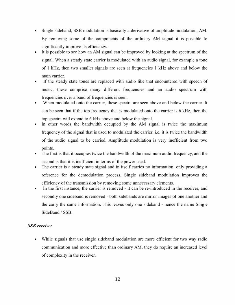
Single sideband, SSB modulation is basically a derivative of amplitude modulation, AM.
By removing some of the components of the ordinary AM signal it is possible to
significantly improve its efficiency. It is possible to see how an AM signal can be improved by looking at the spectrum of the
signal. When a steady state carrier is modulated with an audio signal, for example a tone
of 1 kHz, then two smaller signals are seen at frequencies 1 kHz above and below the
main carrier. If the steady state tones are replaced with audio like that encountered with speech of
music, these comprise many different frequencies and an audio spectrum with
frequencies over a band of frequencies is seen. When modulated onto the carrier, these spectra are seen above and below the carrier. It
can be seen that if the top frequency that is modulated onto the carrier is 6 kHz, then the
top spectra will extend to 6 kHz above and below the signal. In other words the bandwidth occupied by the AM signal is twice the maximum
frequency of the signal that is used to modulated the carrier, i.e. it is twice the bandwidth
of the audio signal to be carried. Amplitude modulation is very inefficient from two
points. The first is that it occupies twice the bandwidth of the maximum audio frequency, and the
second is that it is inefficient in terms of the power used. The carrier is a steady state signal and in itself carries no information, only providing a
reference for the demodulation process. Single sideband modulation improves the
efficiency of the transmission by removing some unnecessary elements. In the first instance, the carrier is removed - it can be re-introduced in the receiver, and
secondly one sideband is removed - both sidebands are mirror images of one another and
the carry the same information. This leaves only one sideband - hence the name Single
SideBand / SSB.
SSB receiver
While signals that use single sideband modulation are more efficient for two way radio
communication and more effective than ordinary AM, they do require an increased level
of complexity in the receiver.
12

As SSB modulation has the carrier removed, this needs to be re-introduced in the
receiver to be able to reconstitute the original audio. This is achieved using an internal
oscillator called a Beat Frequency Oscillator (BFO) or Carrier Insertion Oscillator (CIO).
This generates a carrier signal that can be mixed with the incoming SSB signal, thereby
enabling the required audio to be recovered in the detector.
Typically the SSB detector itself uses a mixer circuit to combine the SSB modulation and
the BFO signals. This circuit is often called a product detector because (like any RF
mixer) the output is the product of the two inputs.
It is necessary to introduce the carrier using the BFO / CIO on the same frequency
relative to the SSB signal as the original carrier.
Any deviation from this will cause the pitch of the recovered audio to change. Whilst
errors of up to about 100 Hz are acceptable for communications applications including
amateur radio, if music is to be transmitted the carrier must be reintroduced on exactly
the correct frequency.
This can be accomplished by transmitting a small amount of carrier, and using circuitry in
the receiver to lock onto this.
Tuning an SSB signal with the BFO set is quite easy. First set the receiver to the SSB position or the BFO to ON, and then if there is a separate
switch set the LSB / USB switch to the format that is expected and then gradually tune
the receiver. Adjust the main tuning control so that the pitch is correct, and the signal should be
comprehensible. If it is not possible to distinguish the sounds, then set the LSB / USB
switch to the other position and re-adjust the main tuning control if necessary to return
the signal to the correct pitch, at which point the signal should be understandable.
SSB advantages
1. As the carrier is not transmitted, this enables a 50% reduction in transmitter power level
for the same level of information carrying signal. [NB for an AM transmission using13

100% modulation, half of the power is used in the carrier and a total of half the power in
the two sideband - each sideband has a quarter of the power.]
2. As only one sideband is transmitted there is a further reduction in transmitter power.
3. As only one sideband is transmitted the receiver bandwidth can be reduced by half. This
improves the signal to noise ratio by a factor of two, i.e. 3 dB, because the narrower
bandwidth used will allow through less noise and interference.
6. Explain in detail about DSB-SC. Transmission in which frequencies produced by amplitude modulation are symmetrically
spaced above and below the carrier frequency and the carrier level is reduced to thelowest practical level, ideally completely suppressed.
The wave carrier is not transmitted but a great percentage of power that is dedicated to itis distributed between the sidebands, which implies an increase of the cover in DSB-SC,compared to AM, for the same power used.
DSB-SC transmission is a special case of Double-sideband reduced carrier transmission. This is used for RDS (Radio Data System) because it is difficult to decouple.
14

DSB-SC implementation
15

• Advantages: – Lower power consumption
• Disadvantage: - Complex detection
• Applications: - Analogue TV systems: to transmit color information - For transmitting stereo information in FM sound broadcast at VHF
7. Compare NBFM and WBFM in detail.
16

8. Draw and explain Armstrong method in detail.FM Transmitter (Armstrong Method)Advantages of FM
1. Transmitted power remains constant. 2. FM receivers are immune to noise. 3. Good capture effect. 4. No mixing of signals.
Disadvantages of FM The greatest disadvantages of FM are: 1. It uses too much spectrum space. 2. The bandwidth is wider. 3. The modulation index can be kept low to minimize the bandwidth used. 4. But reduction in M.I. reduces the noise immunity. 5. Used only at very high frequencies.
Applications of FM 1. FM radio broadcasting. 2. Sound transmission in TV. 3. Police wireless.
9. Explain in detail about Reactance modulations.
17

Limitations of Direct Method of FM Generation 1.In this method, it is very difficult to get high order stability in carrier frequency becausein this method the basic oscillator is not a stable oscillator, as it is controlled by themodulating signal.
2. Generally in this method we get distorted FM, due to non-linearity of thevaractor diode. 10. Compare AM and FM in detail.
18

UNIT-II
1. Draw and explain various pulse modulation technique in detail.
Pulse-amplitude modulation, acronym PAM, is a form of signal modulation where themessage information is encoded in the amplitude of a series of signal pulses.
Demodulation is performed by detecting the amplitude level of the carrier at everysymbol period.
Types Of PAM• 1.Single polarity PAM: In this a suitable fixed dc level is added to the signal to ensure
that all the pulses are positive going.• 2.Double polarity PAM: In this the pulses are both positive and negative going.
Pulse-amplitude modulation is widely used in baseband transmission of digital data, with non-baseband applications having been largely replaced by pulse-code modulation, and, morerecently, by pulse-position modulation
Pulse Width Modulation
19

• Pulse-width modulation (PWM), or pulse-duration modulation (PDM), is a commonlyused technique for controlling power to inertial electrical devices, made practical bymodern electronic power switches.
• The PWM switching frequency has to be much faster than what would affect the load,which is to say the device that uses the power.
• The main advantage of PWM is that power loss in the switching devices is very low.
PWM has also been used in certain communication systems where its duty cycle has been usedto convey information over a communications channel
Types of PWM
• Three types of pulse-width modulation (PWM) are possible:
• The pulse center may be fixed in the center of the time window and both edges of thepulse moved to compress or expand the width.
• The lead edge can be held at the lead edge of the window and the tail edge modulated.
• The tail edge can be fixed and the lead edge modulated.
• Pulse-position modulation (PPM) is a form of signal modulation in which M messagebits are encoded by transmitting a single pulse in one of possible time-shifts
20

• One of the key difficulties of implementing this technique is that the receiver must beproperly synchronized to align the local clock with the beginning of each symbol.Therefore, it is often implemented differentially as differential pulse-position modulation,whereby each pulse position is encoded relative to the previous, such that the receivermust only measure the difference in the arrival time of successive pulses.
• It is possible to limit the propagation of errors to adjacent symbols, so that an error inmeasuring the differential delay of one pulse will affect only two symbols, instead ofaffecting all successive measurements.
2. Explain in detail about QPSK with suitable diagrams.
Quadrature Phase Shift Keying (QPSK) can be interpreted as two independent BPSKsystems (one on the I-channel and one on Q-channel), and thus the same performance buttwice the bandwidth (spectrum) efficiency.
21

Quadrature Phase Shift Keying has twice the bandwidth efficiency of BPSK since 2 bitsare transmitted in a single modulation symbol
Conventional QPSK has transitions through zero (i.e. 1800 phase transition). Highlylinear amplifiers required.
In Offset QPSK, the phase transitions are limited to 900, the transitions on the I and Qchannels are staggered.
In /4 QPSK the set of constellation points are toggled each symbol, so transitions
through zero cannot occur. This scheme produces the lowest envelope variations.
All QPSK schemes require linear power amplifiers
Also a type of linear modulation scheme
Quadrature Phase Shift Keying (QPSK) has twice the bandwidth efficiency of BPSK,since 2 bits are transmitted in a single modulation symbol.
4. Explain in detail about sampling techniques.Many signals originate as continuous-time signals, e.g. conventional music or voiceBy sampling a continuous-time signal at isolated, equally-spaced points in time, weobtain a sequence of numbers
• Replicates spectrum of continuous-time signalAt offsets that are integer multiples of sampling frequency
• Fourier series of impulse train where ws = 2 π fs
22

23

5. Draw and explain ASK and FSK in detail.
ASK
Pulse shaping can be employed to remove spectral spreadingASK demonstrates poor performance, as it is heavily affected by noise, fading, andinterference
FSK
FSK can be expanded to a M-ary scheme, employing multiple frequencies as differentstates
6. Explain in detail about PSK and BPSK.PSK
24

Major drawback – rapid amplitude change between symbols due to phase discontinuity,which requires infinite bandwidth. Binary Phase Shift Keying (BPSK) demonstratesbetter performance than ASK and BFSKBPSK can be expanded to a M-ary scheme, employing multiple phases and amplitudes asdifferent states
Binary Phase Shift Keying (BPSK)
If the sinusoidal carrier has an amplitude Ac and energy per bit Eb
Then the transmitted BPSK signal is either:
Generation of BPSK
25

BPSK signal in time domain
BPSK demodulation
Linear Modulation Techniques:
Digital modulation can be broadly classified as:
1. Linear (change Amplitude or phase)
2. Non linear modulation techniques (change frequency).
Linear Modulation Techniques:
• The amplitude /phase of the transmitted signal s(t), varies linearly with the modulatingdigital signal, m(t).
26

• These are bandwidth efficient (because it doesn’t change frequency) and hence are veryattractive for use in wireless communication systems where there is an increasing demandto accommodate more and more users within a limited spectrum.
• Linear Modulation schemes have very good spectral efficiency,
• However, they must be transmitted using linear RF amplifiers which have poor powerefficiency.
• Phase modulation” can be regarded as “amplitude” modulation because it can reallychange “envelope
7. Draw and explain Pulse Code Modulation in detail.
Pulse-code modulation (PCM) is a method used to digitally represent sampled analogsignals. It is the standard form of digital audio in computers, compact discs, digitaltelephony and other digital audio applications. In a PCM stream, the amplitude of theanalog signal is sampled regularly at uniform intervals, and each sample is quantized tothe nearest value within a range of digital steps.Merits
The PCM (pulse code modulation) convenient for long distance communication. It has a higher transmitter efficiency.
It has a higher noise immunity.
27

Demerits
The PCM (pulse code modulation) requires large bandwidth as compared to analogsystem.
Encoding, decoding and quantizing circuit of PCM is very complex.
Applications
The PCM is used in the satellite transmission system. It is used in space communication.
It is used in telephony.
The compact disc (CD) is a recent application of PCM.
8. Explain in detail about QAM.
Quadrature Amplitude Modulation or QAM is a form of modulation which is widely usedfor modulating data signals onto a carrier used for radio communications. It is widelyused because it offers advantages over other forms of data modulation such as PSK,although many forms of data modulation operate alongside each other.
Quadrature Amplitude Modulation, QAM is a signal in which two carriers shifted inphase by 90 degrees are modulated and the resultant output consists of both amplitudeand phase variations. In view of the fact that both amplitude and phase variations arepresent it may also be considered as a mixture of amplitude and phase modulation.
A motivation for the use of quadrature amplitude modulation comes from the fact that astraight amplitude modulated signal, i.e. double sideband even with a suppressed carrieroccupies twice the bandwidth of the modulating signal.
This is very wasteful of the available frequency spectrum. QAM restores the balance byplacing two independent double sideband suppressed carrier signals in the same spectrumas one ordinary double sideband suppressed carrier signal.
28
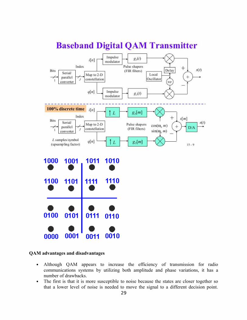
QAM advantages and disadvantages
Although QAM appears to increase the efficiency of transmission for radiocommunications systems by utilizing both amplitude and phase variations, it has anumber of drawbacks.
The first is that it is more susceptible to noise because the states are closer together sothat a lower level of noise is needed to move the signal to a different decision point.
29

Receivers for use with phase or frequency modulation are both able to use limitingamplifiers that are able to remove any amplitude noise and thereby improve the noisereliance. This is not the case with QAM.
The second limitation is also associated with the amplitude component of the signal.When a phase or frequency modulated signal is amplified in a radio transmitter, there isno need to use linear amplifiers, whereas when using QAM that contains an amplitudecomponent, linearity must be maintained.
Unfortunately linear amplifiers are less efficient and consume more power, and thismakes them less attractive for mobile applications.
9. Explain in detail about MSK and GMSK.
MSK and GMSK stands for Minimum Shift Keying and Gaussian Minimum Shift Keyingrespectively. GMSK is derivative of base MSK modulation scheme. As we know, sidebandsof standard PSK modulated spectrum extend from carrier frequency. This is overcome byMSK and GMSK.
Representation of MSK
30

MSK transmitter
MSK Receiver
31

Following are the benefits or advantages of MSK or GMSK:
The sidebands of PSK modulated spectrum is minimized by this modulation technique. Hence sideband power is reduced. The MSK or GMSK spectrum is less affected by noise and hence leads to good SNR. This helps in achieving very stable and long distance communication. Due to this fact, the GMSK modulation technique is being employed in GSM technology. Above fact, helps in achieving good receiver sensitivity. PAPR is maintained low due to no phase continuities and occurrence of frequency changes at zero cross over of RF carrier. Due to this, highly linear PA (Power Amplifier) is not required. Spectral efficiency is better and higher while demodulator is less complex. GMSK provides constant envelope over the entire bandwidth. Hence it offers excellent power efficiency. It provides good BER performance. GMSK offers self synchronizing capabilities. GMSK is good choice for voice modulation.
Following are the disadvantages of MSK or GMSK:PSD of MSK does not fall fast and hence Interference between adjacent channels is observed. GMSK uses BT of 0.3 and hence good rejection can be achieved between adjacent channels. Here B is 3dB bandwidth of shaping filter and T is bit duration.
32

Both MSK and GMSK requires more power to transmit data compare to other modulation types such as QPSK.It requires complex channel equalization algorithms e.g. adaptive equalizer at receiver. Inter symbol interference may occur.
10. Write notes on coherent and non-coherent detection.Coherent DetectionAn estimate of the channel phase and attenuation is recovered. It is then possible to reproduce the transmitted signal and demodulate. Requires a replica carrier wave of the same frequency and phase at the receiver. Also known as synchronous detection (I.e. carrier recovery)Carrier recovery methods include
Pilot Tone (such as Transparent Tone in Band) Less power in the information bearing signal, High peak-to-mean power
ratio Carrier recovery from the information signal
E.g. Costas loopApplicable to
Phase Shift Keying (PSK) Frequency Shift Keying (FSK) Amplitude Shift Keying (ASK)
Non-Coherent Detection Requires no reference wave; does not exploit phase reference information (envelope
detection) Differential Phase Shift Keying (DPSK) Frequency Shift Keying (FSK) Amplitude Shift Keying (ASK) Non coherent detection is less complex than coherent detection (easier to
implement), but has worse performance.
UNIT-III
1. Explain in detail about error control codes and its applications.
• Channel is noisy• Channel output prone to error
•We need measure to ensure correctness of the bit stream transmitted Error control coding aims at developing methods for coding to check the correctness of
the bit stream transmitted. The bit stream representation of a symbol is called the codeword of that symbol.
– Extra bits are added to the data at the transmitter (redundancy) to permit error detection or correction at the receiver
– Done to prevent the output of erroneous bits despite noise and other imperfectionsin the channel
33

– The positions of the error control coding and decoding are shown in the transmission model
Error Models
• Binary Symmetric Memoryless Channel
– Assumes transmitted symbols are binary
– Errors affect ‘0’s and ‘1’s with equal probability (i.e., symmetric)
– Errors occur randomly and are independent from bit to bit (memoryless)
34

p is the probability of bit error or the Bit Error Rate (BER) of the channel
• Many other types
• Burst errors, i.e., contiguous bursts of bit errors
– output from DFE (error propagation)
– common in radio channels
– Insertion, deletion and transposition errors
• We will consider mainly random errors
Error Control Techniques
• Error detection in a block of data
– Can then request a retransmission, known as automatic repeat request (ARQ) for sensitive data
– Appropriate for
• Low delay channels
• Channels with a return path
– Not appropriate for delay sensitive data, e.g., real time speech and data
• Forward Error Correction (FEC)
– Coding designed so that errors can be corrected at the receiver
– Appropriate for delay sensitive and one-way transmission (e.g., broadcast TV) of data
– Two main types, namely block codes and convolutional codes. We will only look at block codes
Applications
Useful in satellite communication
Useful in TV communication
2. Write short notes on BSE and BEC.
BEC- Binary Erasure Channel
35

• BEC
C = 1 – ε ,
where ε is the erasure probability.
• BSC
C = 1 – H(ρ) ,
where ρ is the error probability of the channel and H(ρ ) is the entropy with the parameter ρ.
• Benefits
– In principle:
• If you transmit information at a rate R < C, then the error-free transmissionis possible.
– In practice:
• Reduce the error rates
• Reduce the transmitted power requirements
3. Explain in detail about noise coding theorem.
In information theory, the noisy-channel coding theorem (sometimes Shannon's theorem), establishes that for any given degree of noise contamination of a communication channel, it is possible to communicate discrete data (digital information) nearly error-free up to a computable maximum rate through the channel.
The Shannon limit or Shannon capacity of a communications channel is the theoretical maximum information transfer rate of the channel, for a particular noise level.
Theorem
1. For every discrete memoryless channel, the channel capacity
36

2. If a probability of bit error pb is acceptable, rates up to R(pb) are achievable
3. For any pb, rates greater than R(pb) are not achievable.
4. Draw and explain any two SNR trade off codes.
By increasing the bandwidth alone, the capacity cannot be increased to any desired value.
NRZ - In telecommunication, a non-return-to-zero line code is a binary code in which ones are
represented by one significant condition, usually a positive voltage, while zeros are represented bysome other form.
RZ- RZ (return-to-zero) refers to a form of digital data transmission in which the binary low and high states, represented by numerals 0 and 1, are transmitted by voltage pulses having certain characteristics
There exists a limiting value of below which there can be no error-free communication at any information rate.
37

. The signal state is determined by the voltage during the first half of each data binary digit .
5. Write notes on Error-correcting codes.
Error-correcting codes at fixed SNR influence the error performance in two ways:
1. Improving effect:
The larger the redundancy, the greater the error-correction capability
2. Degrading effect:
Energy reduction per channel symbol or coded bits for real-time applications due
to faster signaling.
3. The degrading effect vanishes for non-real time applications when delay is tolerable, since the channel symbol energy is not reduced.
38
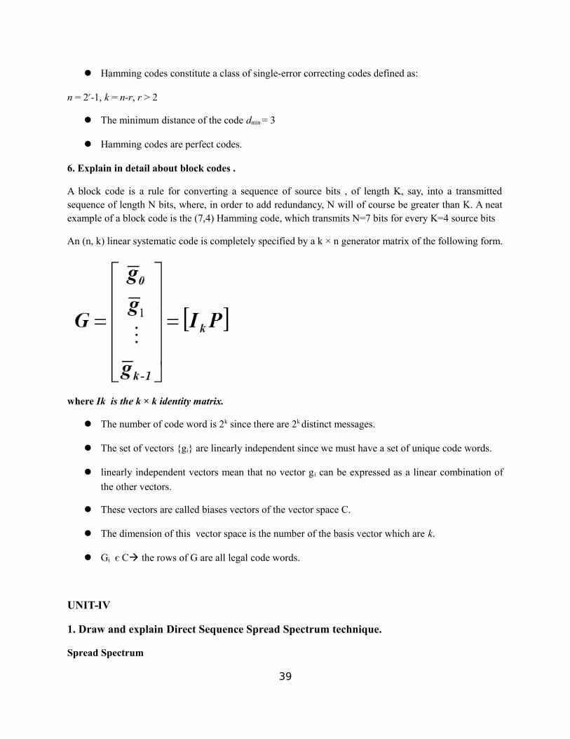
Hamming codes constitute a class of single-error correcting codes defined as:
n = 2r-1, k = n-r, r > 2
The minimum distance of the code dmin = 3
Hamming codes are perfect codes.
6. Explain in detail about block codes .
A block code is a rule for converting a sequence of source bits , of length K, say, into a transmittedsequence of length N bits, where, in order to add redundancy, N will of course be greater than K. A neatexample of a block code is the (7,4) Hamming code, which transmits N=7 bits for every K=4 source bits
An (n, k) linear systematic code is completely specified by a k × n generator matrix of the following form.
where Ik is the k × k identity matrix.
The number of code word is 2k since there are 2k distinct messages.
The set of vectors {gi} are linearly independent since we must have a set of unique code words.
linearly independent vectors mean that no vector g i can be expressed as a linear combination of
the other vectors.
These vectors are called biases vectors of the vector space C.
The dimension of this vector space is the number of the basis vector which are k.
Gi є Cà the rows of G are all legal code words.
UNIT-IV
1. Draw and explain Direct Sequence Spread Spectrum technique.
Spread Spectrum
39

In spread spectrum (SS), we combine signals from different sources to fit into a larger bandwidth, but ourgoals are to prevent eavesdropping and jamming. To achieve these goals, spread spectrum techniques addredundancy.
DSSS
In DS-SS, the message signal is multiplied by a Pseudo Random Noise Code (PN code), which has noise-like properties. Each user has his own codeword which is orthogonal to the codes of other users. In orderto detect the user, the receiver is required to know the codeword used by the transmitter. Unlike TDMA,CDMA does not require time synchronization between the users.
40

2. Explain in detail about FDMA.
FDMA is one of the earliest multiple-access techniques for cellular systems when continuous
transmission is required for analog services. In this technique the bandwidth is divided into a number of
channels and distributed among users with a finite portion of bandwidth for permanent use. The vertical
axis that represents the code is shown here just to make a clear comparison with CDMA (discussed later
in this chapter). The channels are assigned only when demanded by the users. Therefore when a channel
is not in use it becomes a wasted resource. FDMA channels have narrow bandwidth (30Khz). For this
reason, although x[n] is strictly the nth number in the sequence, we often refer to it as the nth sample. We
also often refer to \the sequence x[n]" when we mean the entire sequence. Discrete-time signals are often
depicted graphically as follows:
They are usually implemented in narrowband systems. Since the user has his portion of the
bandwidth all the time, FDMA does not require synchronization or timing control, which makes it
algorithmically simple. Even though no two users use the same frequency band at the same time, guard
bands are introduced between frequency bands to minimize adjacent channel interference. Guard bands
are unused frequency slots that separate neighboring channels. This leads to a waste of bandwidth. When
continuous transmission is not required, bandwidth goes wasted since it is not being utilized for a portion
of the time. In wireless communications, FDMA achieves simultaneous transmission and reception by
using Frequency division duplexing (FDD). In order for both the transmitter and the receiver to operate at
the same time, FDD requires duplexers.
41
4. Explain in detail about TDMA.
In digital systems, continuous transmission is not required because users do not use the allotted
bandwidth all the time. In such systems, TDMA is a complimentary access technique to FDMA.
Global Systems for Mobile communications (GSM) uses the TDMA technique. In TDMA, the entire
bandwidth is available to the user but only for a finite period of time. In most cases the available
bandwidth is divided into fewer channels compared to FDMA and the users are allotted time slots
during which they have the entire channel bandwidth at their disposal. TDMA requires careful time
synchronization since users share the bandwidth in the frequency domain. Since the number of
channels are less, inter channel interference is almost negligible, hence the guard time between the
channels is considerably smaller. Guard time is a spacing in time between the TDMA bursts. In
cellular communications, when a user moves from one cell to another there is a chance that user could
experience a call loss if there are no free time slots available. TDMA uses different time slots for
transmission and reception. This type of duplexing is referred to as Time division duplexing (TDD).
TDD does not require duplexers.
5. Explain in detail about CDMA.
Code Division Multiple Access
In CDMA, all the users occupy the same bandwidth, however they are all assigned
separate codes, which differentiates them from each other.
CDMA systems utilize a spread spectrum technique in which a spreading signal, which
is uncorrelated to the signal and has a large bandwidth, is used to spread the narrow band
message signal.
Direct Sequence Spread Spectrum (DS-SS) is most commonly used for CDMA.
In DS-SS, the message signal is multiplied by a Pseudo Random Noise Code (PN code),
which has noise-like properties.
Each user has his own codeword which is orthogonal to the codes of other users. In order
to detect the user, the receiver is required to know the codeword used by the transmitter.
Unlike TDMA, CDMA does not require time synchronization between the users.
42

A CDMA system experiences a problem called self-jamming which arises when the
spreading codes used for different users are not exactly orthogonal. While dispreading,
this leads to a significant contribution from other users to the receiver decision statistic. If
the power of the multiple users in a CDMA system is unequal, then the user with the
strongest signal power will be demodulated at the receiver.
The strength of the received signal raises the noise floor for the weaker signals at the
demodulators.
This reduces the probability that weaker signals will be received. This problem, known
as the near-far problem can be taken care of by using power control.
This ensures that all the signals within the coverage of the base station arrive with same
power at the receiver.
6. Write notes on SDMA.
Space Division Multiple Access (SDMA)
SDMA utilizes the spatial separation of the users in order to optimize the use of the frequency
spectrum.
A primitive form of SDMA is when the same frequency is re-used in different cells in a cellular
wireless network.
However for limited co-channel interference it is required that the cells be sufficiently separated.
This limits the number of cells a region can be divided into and hence limits the frequency re-use
factor.
A more advanced approach can further increase the capacity of the network. This technique
would enable frequency re-use within the cell.
It uses a Smart Antenna technique that employs antenna arrays backed by some intelligent signal
processing to steer the antenna pattern in the direction of the desired user and places nulls in the
direction of the interfering signals.
Since these arrays can produce narrow spot beams, the frequency can be re-used within the cell as
long as the spatial separation between the users is sufficient.43

In a practical cellular environment it is improbable to have just one transmitter fall within the
receiver beam width.
Therefore it becomes imperative to use other multiple access techniques in conjunction with
SDMA.
When different areas are covered by the antenna beam, frequency can be re-used, in which case
TDMA or CDMA is employed, for different frequencies FDMA can be used.
7. Draw and explain Frequency Hop Spread Spectrum technique.
44

FHSS cycles
Bandwidth sharing
45

A signal that occupies a bandwidth of B, is spread out to occupy a bandwidth of Bss
All signals are spread to occupy the same bandwidth Bss
Signals are spread with different codes so that they can be separated at the receivers.
Signals can be spread in the frequency domain or in the time domain.
8. Write notes on merits and applications wireless communication.
Wireless communications
Applications
Communication radio
Wireless networks
Cellular phones
Short range communication
advantages:
mobility
a wireless communication network is a solution in areas where cables are
impossible to install (e.g. hazardous areas, long distances etc.)
easier to maintain
disadvantages:
has security vulnerabilities
high costs for setting the infrastructure
unlike wired comm., wireless comm. is influenced by physical obstructions,
climatic conditions, interference from other wireless devices
UNIT-V
1. Explain in detail about satellite and types of orbits.
46

A satellite communication system will have a number of users operating via a common satellite
transponder, and this calls for sharing of the resources of power, bandwidth and time.
Here we describe these techniques and examine their implications, with emphasis on principles
rather than detailed structure or parameters of particular networks, which tend to be very system
specific.
The term used for such sharing and management of a number of different channels is multiple
access.
Types of Satellite Orbits
There are three basic kinds of orbits, depending on the satellite's position relative to Earth's surface:
Geostationary orbits (also called geosynchronous or synchronous) are orbits in which the
satellite is always positioned over the same spot on Earth. Many geostationary satellites are above
a band along the equator, with an altitude of about 22,223 miles, or about a tenth of the distance
to the Moon. The "satellite parking strip" area over the equator is becoming congested with
several hundred television, weather and communication satellites! This congestion means each
satellite must be precisely positioned to prevent its signals from interfering with an adjacent
satellite's signals. Television, communications and weather satellites all use geostationary orbits.
Geostationary orbits are why a DSS satellite TV dish is typically bolted in a fixed position.
The scheduled Space Shuttles use a much lower, asynchronous orbit, which means they pass
overhead at different times of the day. Other satellites in asynchronous orbits average about 400
miles (644 km) in altitude.
In a polar orbit, the satellite generally flies at a low altitude and passes over the planet's poles on
each revolution. The polar orbit remains fixed in space as Earth rotates inside the orbit. As a
result, much of Earth passes under a satellite in a polar orbit. Because polar orbits achieve
excellent coverage of the planet, they are often used for satellites that do mapping and
photography.
2. Explain in detail about optical fibre and its types.
OPTICAL FIBRE:
47

An optical fiber is a flexible, transparent fiber made of very pure glass (silica) not much
bigger than a human hair that acts as a waveguide, or "light pipe", to transmit light
between the two ends of the fiber.
The field of applied science and engineering concerned with the design and application
of optical fibers is known as fiber optics.
Optical fibers are widely used in fiber-optic communications, which permits transmission
over longer distances and at higher bandwidths (data rates) than other forms of
communication.
Fibers are used instead of metal wires because signals travel along them with less loss
and are also immune to electromagnetic interference.
Fibers are also used for illumination, and are wrapped in bundles so they can be used to
carry images, thus allowing viewing in tight spaces. Specially designed fibers are used
for a variety of other applications, including sensors and fiber lasers.
An optical fiber junction box. The yellow cables are single mode fibers; the orange and
blue cables are multi-mode fibers: 50/125 µm OM2 and 50/125 µm OM3 fibers
respectively.
Optical fiber typically consists of a transparent core surrounded by a transparent cladding
material with a lower index of refraction. Light is kept in the core by total internal
reflection. This causes the fiber to act as a waveguide.
Fibers that support many propagation paths or transverse modes are called multi-mode
fibers (MMF), while those that only support a single mode are called single-mode fibers
(SMF).
Multi-mode fibers generally have a larger core diameter, and are used for short-distance
communication links and for applications where high power must be transmitted. Single-
mode fibers are used for most communication links longer than 1,050 meters (3,440 ft).
48

3. Explain in detail about various types of optical detectors used in communication.
The detection of optical radiation is usually accomplished by converting the optical energy into
an electrical signal.
Optical detectors include photon detectors, in which one photon of light energy releases one
electron that is detected in the electronic circuitry, and thermal detectors, in which the optical
energy is converted into heat, which then generates an electrical signal.
Often the detection of optical energy must be performed in the presence of noise sources, which
interfere with the detection process.
The detector circuitry usually employs a bias voltage and a load resistor in series with the
detector.
The incident light changes the characteristics of the detector and causes the current flowing in
the circuit to change.
The output signal is the change in voltage drop across the load resistor. Many detector circuits
are designed for specific applications.
Avalanche photodetectors (APDs) are used in long-haul fiber optic systems, since they have
superior sensitivity, as much as 10 dB better than PIN diodes. Basically, an APD is a P-N junction
photodiode operated with high reverse bias.
The materials is typically InP/InGaAs. With the high applied potential, impact ionization from
the light wave generates electron-hole pairs that subsequently cause an avalanche across the potential
barrier. This current gain gives the APD its greater sensitivity. APDs are commonly used up to 2.5 Gbps
and sometimes to 10 Gbps if the extra cost can be justified.
Silicon photodiodes (APDs) are used in lower frequency systems (up to 1.5 or 2 GHz) where
they can meet low cost and modest frequency response requirements.
Si devices are used in pairs in wavelength sensors. The ratio of longer and shorter wavelength
sensors is proportional to the input wavelength. Hopefully, this short tutorial provides a useful
introduction to an important part of optical communication systems.
4. Write notes on INSAT and INTELSAT.
49

INSAT
The Indian National Satellite (INSAT) system was commissioned with the launch of INSAT-1B in
August 1983 (INSAT-1A, the first satellite was launched in April 1982 but could not fulfil themission).
INSAT system ushered in a revolution in India’s television and radio broadcasting,
telecommunications and meteorological sectors.
It enabled the rapid expansion of TV and modern telecommunication facilities to even the remote
areas and off-shore islands. Together, the system provides transponders in C, Extended C and Ku
bands for a variety of communication services.
Some of the INSATs also carry instruments for meteorological observation and data relay for
providing meteorological services. KALPANA-1 is an exclusive meteorological satellite. Thesatellites are monitored and controlled by Master Control Facilities that exist in Hassan andBhopal.
INTELSAT
Intelsat, S.A. is a communications satellite services provider. Originally formed as InternationalTelecommunications Satellite Organization (ITSO, or INTELSAT), it was—from 1964 to 2001—anintergovernmental consortium owning and managing a constellation of communications satellitesproviding international broadcast services.
5. Explain various optical sources in detail.
The basic concept behind the optical transmitter is that it converts electrical input signals into modulatedlight for transmission over an optical fiber used optical sources for generating the light pulses. These arelight emitting diode (LED) and Laser Diode (LD).
LEDs
SLEDs – Surface Emitting LEDs
ELEDs – Edge Emitting LEDs
LDs – Laser Diodes
Tunable Lasers
LED
Emits incoherent light through spontaneous emission.
Used for Multimode systems w/ 100-200 Mb/s rates.
50

Broad spectral width and wide output pattern.
850nm region: GaAs and AlGaAs
1300–1550nm region: InGaAsP and InP
Two commonly used types: ELEDs and SLEDs
51