DEVIreg™ 316 - Danfossfheprod.danfoss.com/PCMPDF/DEVIreg316_X005344_VICKF402.pdfDEVIreg 316 is an...
12
DEVIreg™ 316 Electronic Thermostat Installation Guide www.DEVI.com
Transcript of DEVIreg™ 316 - Danfossfheprod.danfoss.com/PCMPDF/DEVIreg316_X005344_VICKF402.pdfDEVIreg 316 is an...

The English language is used for the original instructions.Other languages are a translation of the original instructions.(Directive 2006/42/EC)

Table of Contents
1 Introduction . . . . . . . . . . . . . . . 31.1 Technical Specifications . . . . . 41.2 Safety Instructions . . . . . . . . 5
2 Mounting Instructions . . . . . . . . . 6
3 Settings . . . . . . . . . . . . . . . . . 83.1 Hysteresis . . . . . . . . . . . . . 83.2 Minimum Temperature Limiter 93.3 Temperature Set-back . . . . . . 10
4 Warranty . . . . . . . . . . . . . . . . . 10
5 Disposal Instruction . . . . . . . . . . 10
1 Introduction
DEVIreg™ 316 is an electronic thermostat to be installed inelectric cabinets with DIN rail attachment. The thermostatmust be installed via an all-pole disconnection switch.DEVIreg™ 316 applies to the control of room temperature,floor temperature, ventilation, cooling or to the control ofsnow melting in gutters and similar installations.
For measuring purposes either a wire sensor or an externalair sensor is used.
DEVIreg™ 316
Installation Guide 3

The thermostat has a button to adjust the temperature set-ting with a scale from -10°C to +50°C . An LED indicatorshows standby periods (green light) and heating periods(red light).
More information on this product can also be found at:devireg.devi.com
1.1 Technical Specifications
Operation voltage 220-240V~, 50Hz
Standby power consumption Max 0.25W
Relay:
Resistive loadInductive load
Max 16A / 3680W @ 230Vcos φ= 0.3 max1A
Sensing units NTC 15kOhm at 25°C
Sensing values:
0°C25°C50°C
42kOhm15kOhm6kOhm
Hysteresis 0 to 6°C
Ambient temperature 10°C to +45°C
Lowering in economy periods 0 to 8°C
Temperature range -10°C to +50°C
DEVIreg™ 316
4 Installation Guide

Minimum temperature range -10°C to +5°C
Cable specification max 1x4mm2 or 2x2,5mm2
Ball pressure temperature 75°C
Pollution degree 2 (domestic use)
Type 1B
Storage temperature -20°C to +65°C
IP class 30
Protection class Class II -
Dimensions 86 x 36 x 58mm
Weight 180g
The product complies with the EN/IEC Standard "Automaticelectrical controls for household and similar use":
▪ EN/IEC 60730-1 (general)▪ EN/IEC 60730-2-9 (thermostat)
1.2 Safety Instructions
Make sure the mains supply to the thermostat is turned offbefore installation.
IMPORTANT: When the thermostat is used to control afloor heating element in connection with a wooden floor orsimilar material, always use a floor sensor and never set themaximum floor temperature to more than 35°C.
DEVIreg™ 316
Installation Guide 5
Please also note the following:
▪ The installation of the thermostat must be done by anauthorized and qualified installer according to localregulations.
▪ The thermostat must be connected to a power supplyvia an all-pole disconnection switch.
▪ Always connect the thermostat to continuous powersupply.
▪ Do not expose the thermostat to moisture, water, dust,and excessive heat.
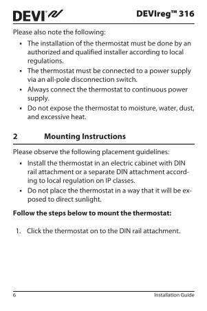
2 Mounting Instructions
Please observe the following placement guidelines:
▪ Install the thermostat in an electric cabinet with DINrail attachment or a separate DIN attachment accord-ing to local regulation on IP classes.
▪ Do not place the thermostat in a way that it will be ex-posed to direct sunlight.
Follow the steps below to mount the thermostat:
1. Click the thermostat on to the DIN rail attachment.
DEVIreg™ 316
6 Installation Guide
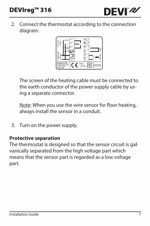
2. Connect the thermostat according to the connectiondiagram.
IP20
-10T50 D3161
211
10
98
7
L65
43
21
NMa
ins
22
0-2
40
V~
25
0V
~
16
(1) A
Se
nso
rM
in.
Danfoss A/SUlvehavevej 617100 VejleDenmark
The screen of the heating cable must be connected tothe earth conductor of the power supply cable by us-ing a separate connector.
Note: When you use the wire sensor for floor heating,always install the sensor in a conduit.
3. Turn on the power supply.
Protective separationThe thermostat is designed so that the sensor circuit is gal-vanically separated from the high voltage part whichmeans that the sensor part is regarded as a low voltagepart.
DEVIreg™ 316
Installation Guide 7

3 Settings
A Night set-back
B Minimum tempera-ture limiter
C Hysteresis
3.1 Hysteresis
When the thermostat is used to apply with either heatingsystems or refrigerating systems, and the requested tem-perature is between -10°C to +50°C, then it is recommenda-ble also to adjust the hysteresis C according to the reques-ted regulating range.
As an example if the temperature is set at 18°C and the hys-teresis at 3°C the thermostat will switch on at 18°C and offat 21°C.
For controlling of room temperature the Hysteresis is rec-ommended to the set point of 1°C.
DEVIreg™ 316
8 Installation Guide

3.2 Minimum Temperature Limiter
When the thermostat is used in connection with snow andice melting systems, it is recommendable also to use andadjust the minimum temperature limiter (B) which ensuresboth an upper and lower temperature range in betweenwhich the thermostat allows the system to heat.
The requested maximum temperature range has to be be-tween -10°C to +50°C and the requested minimum temper-ature range has to be between -10°C to +5°C.
An link between terminal 9+10 must be connected to acti-vate the use of the minimum temperature feature whenthe thermostat controls snow and ice melting in gutters,valley gutters and down pipes, where the waste of unnec-essary energy must be avoided. In particular by extremelycold weather where flowing water or moisture does not oc-cur.
When the temperature drops below the minimum temper-ature set value, the thermostat stops heating and the LEDindicator turns yellow.
When the temperature exceeds the maximum temperaturesetting, the thermostat stops heating and both the indica-tor for minimum and maximum temperature disappears.
DEVIreg™ 316
Installation Guide 9

3.3 Temperature Set-back
By connecting an external timer to terminals 4 and 6, thethermostat can be set to reduce the temperature by 0°C to8°C (A).
4 Warranty
5 Disposal Instruction
DEVIreg™ 316
10 Installation Guide

DEVIreg™ 316
Danfoss A/SElectric Heating SystemsUlvehavevej 617100 VejleDenmarkPhone: +45 7488 8500Fax: +45 7488 8501E-mail: [email protected]
Danfoss can accept no responsibility for possible errors in catalogues, brochures and other printed material. Danfoss reserves the right to alter itsproducts without notice. This also applies to products already on order provided that such alterations can be made without subsequential changesbeing necessary in specifications already agreed. All trademarks in this material are property of the respective companies. DEVI and the DEVI logo-type are trademarks of Danfoss A/S. All rights reserved.
08095512 & VICKF402 Produced by Danfoss © 06/2012

DEV
Ireg
316
-10<
>+
50°
140F
1075
220-
240V
~50
-60H
z~-1
0 to
+50
°CEC
O S
et b
ack
0-8°
C16
A/3
680W
@23
0V~
Prod
uct D
ocum
enta
tion
DK
EL 7
2242
1533
1SE
EL
8581
194
NO
EL
5491
480
FI S
STL
3531
017
Des
igne
d in
Den
mar
k fo
r Dan
foss
A/S
5703466
209240