DeviceNet Planning and Installation Manual
98
Planning and Installation Manual DeviceNet TM Cable System © Copyright 2002-2003, ODVA. All rights reserved. DeviceNet™ is a trademark of ODVA. PUB00027R1
-
Upload
bangunprayogi -
Category
Documents
-
view
1.275 -
download
4
description
DNet Planning & Installation in details from ODVA.
Transcript of DeviceNet Planning and Installation Manual

Planning and Installation Manual
DeviceNetTM Cable System
© Copyright 2002-2003, ODVA. All rights reserved.DeviceNet™ is a trademark of ODVA. PUB00027R1

Important User Information Because of the variety of uses for the products described in this publication, those responsible for the application and use of this control equipment must satisfy themselves that all necessary steps have been taken to assure that each application and use meets all performance and safety requirements, including any applicable laws, regulations, codes and standards.
The illustrations, charts, sample programs and layout examples shown in this guide are intended solely for purposes of example. Since there are many variables and requirements associated with any particular installation, ODVA does not assume responsibility or liability (to include intellectual property liability) for actual use based upon the examples shown in this publication.
Reproduction of the contents of this copyrighted publication, in whole or part, without written permission of ODVA, is prohibited.
Throughout this manual we use notes to make you aware of safety considerations:
Attention statements help you to:
• identify a hazard
• avoid a hazard
• recognize the consequences
Important: Identifies information that is critical for successful application and understanding of the product.
!ATTENTION: Identifies information about practices or circumstances that can lead to personal injury or death, property damage or economic loss

Preface
Using This Manual
What’s in This Manual Use this manual to plan and install a DeviceNet™ cable system. This manual describes the required components of the cable system and how to plan for and install these required components.
1
Quikstart and Planning a DeviceNet™ Cable System
Start
Complete
2
3
4
5
A B
IdentifyingComponents
Make cableConnections
CalculatePowerRequirements
SelectedNEC Topics
PoweringOutput
CommissioningTroubleshootingDiagnostics
Devices

P-2 Using This Manual
Who Should Read This Manual
We assume that you have a fundamental understanding of:
• electronics and electrical codes
• basic wiring techniques
• ac and dc power specifications
• load characteristics of the devices attached to the DeviceNet™ network
About the National Electric Code
Much of the information provided in this manual is representative of the capability of a DeviceNetTM network and its associated components. The National Electric Code (NEC), in the United States, and the Canadian Electric Code (CECode), in Canada, places limitations on configurations and the maximum allowable power/current that can be provided. Refer to Appendix A for details.
Common Techniques Used in This Manual
The following conventions are used throughout this manual:
• Bulleted lists provide information, not procedural steps.
• Numbered lists provide sequential steps.
• Information in bold contained within text identifies menu options, screen names and areas of the screen, such as dialog boxes, status bars, radio buttons and parameters.
• Text in this font identifies node addresses and other values assigned to devices.
• Pictures of keys and/or screens represent the actual keys you press or the screens you use.
Important: Be sure that all national and local codes are thoroughly researched and adhered to during the planning and installation of your DeviceNet™ network.
This symbol represents an information tip.

Table Of Contents
Get Started.................................................................................................................. 1–1 What’s in this chapter? ....................................................................................................... 1–1 Set Up a DeviceNetTM Network .......................................................................................... 1–1 Basic DeviceNetTM Network ...................................................................................... 1–2
Understand the Topology........................................................................................... 1–2 Understand the Media......................................................................................................... 1–2
Understand the Cable Options................................................................................... 1–2 Determine the Maximum Trunk Length Distance ..................................................... 1–3 Determine the Cumulative Drop Line Length ............................................................. 1–4 About the Direct Connection ...................................................................................... 1–5
Using Connectors ...................................................................................................... 1–5 Terminate the Network .............................................................................................. 1–7 Guidelines for Supplying Power ................................................................................. 1–9
Supplying Power ................................................................................................................. 1–10
Identify Cable System Components ......................................................................... 2–1 Round (Thick, Mid and Thin) Cable Network ...................................................................... 2–1
About Thick Cable...................................................................................................... 2–2 About Mid Cable ......................................................................................................... 2–3 About Thin Cable ....................................................................................................... 2–3 About Flat Cable ........................................................................................................ 2–4
Connecting to the Trunk Line ............................................................................................. 2–4 About the T-Port Tap.................................................................................................. 2–6
About the Multi Port Tap............................................................................................. 2–7 About the Power Tap.................................................................................................. 2–7 About the Multi Port Tap............................................................................................. 2–8 About the Direct Connection. ..................................................................................... 2–8 About the Open-Style Connector ............................................................................... 2–9 About Flat Cable Insulation Displacement Connectors (IDCs) .................................. 2–10
Using Preterminated Cables ................................................................................................ 2–11 About Thick Cable...................................................................................................... 2–11 About Thin Cable ....................................................................................................... 2–11 About Terminators ..................................................................................................... 2–13
Make Cable Connections........................................................................................... 3–1 Preparing Cables ................................................................................................................ 3–1 How to Install Open-Style Connectors ................................................................................ 3–2
How to Install Mini/Micro Sealed Field-Installable Connectors .................................. 3–3 How to Install Power taps and Multi Port Taps with Terminals ........................................... 3–4
How to Install Multi Port Taps with Sealed Connectors.............................................. 3–5 How to Connect Drop Lines ............................................................................................... 3–5
TOC-1

Flat Cable Installation Instructions ...................................................................................... 3–6 How to Install a Flat Cable Connector........................................................................ 3–6 End Cap Installation ................................................................................................... 3–10 Installing Auxiliary Power Cable ................................................................................. 3–11
Connecting Power Supplies to Round Media...................................................................... 3–11
Determine Power Requirements ............................................................................... 4–1 Use the Look-Up Method .................................................................................................... 4–1
One Power Supply (End-Connected) ......................................................................... 4–11 One Power Supply (Middle-Connected) .......................................................................... 4–12 NEC/CE Code Current Boost Configuration............................................................... 4–14 Two Power Supplies (End-Connected) in Parallel with No V+ Break ..................... 4–15 Two Power Supplies (Not End- Connected) in Parallel with No V+ Break................. 4–16
Use the Full-Calculation Method......................................................................................... 4–18 Using the Equation.............................................................................................................. 4–18
One Power Supply (End-Connected) ......................................................................... 4–20 One Power Supply (Middle-Connected)..................................................................... 4–21
Commissioning Troubleshooting and Diagnostics................................................. 5–1
Network Measurement Tools ............................................................................................. 5–1 Verifying Network Installation.............................................................................................. 5–1 Confirming Media ................................................................................................................ 5–2 Proper Network Maintenance.............................................................................................. 5–4 Common Mode Problems ................................................................................................... 5–4 Bus Errors ........................................................................................................................... 5–5 Bus Traffic Problems........................................................................................................... 5–5 Bus Power Problems........................................................................................................... 5–6 Shield Voltage Problems..................................................................................................... 5–6 Common Faults................................................................................................................... 5–7 Flat Cable Shorts ................................................................................................................ 5–7
Understanding Select NEC Topics ........................................................................... A–1 What’s in This Appendix ..................................................................................................... A–1
Class 1 (CL1) Cable .................................................................................................. A–1 Class 2 (CL 2) Cable.................................................................................................. A–1
Specifying Article 725 Topics.............................................................................................. A–2 Round (Thick, Mid & Thin) and Class 2 Flat Media.................................................... A–2 Class 1 Round or Flat Media...................................................................................... A–2
TOC-2
Table Of Contents

Powering Output Devices.......................................................................................... B–1 Wide Available Voltage Range............................................................................................ B–1 Noise or Transient Protection.............................................................................................. B–2
DeviceNet Baseline & Test Report............................................................................ C–1 Baseline and Test Report.................................................................................................... C–1
Index
TOC-3
Table Of Contents


Chapter 1Get Started
What’s in This Chapter? This chapter introduces the DeviceNetTM cable system and provides a brief overview of how to set up a DeviceNetTM network efficiently. The steps in this chapter describe the basic tasks involved in setting up a network.
Set Up a DeviceNet Network
The following diagram illustrates the steps that you should follow to plan and install a DeviceNetTM network. The remainder of this chapter provides an overview and examples of each step, with references to other sections in this manual for more details.
Basic DeviceNet™ Network
1 Understand the media Refer to page 1-2
2 Terminate the network Refer to page 1-7
3 Supply power Refer to page 1-94 Ground the network Refer to page 1-16
5 Use the checklist Refer to page 1-18
Supply powerrefer to page 1-9
Use the check-listrefer to page 1-18
Groundthe networkrefer to page 1-16
Understand the mediarefer to page 1-2
1
4
Terminate the network refer to page 1-7
5
2
3This figure shows a basic DeviceNet™ network and calls out its basic components.
TR TR
PowerSupply
TR terminating resistor
device or node
1
3,4
22
Checklist
5
trunk linedrop lines
ODVA 2002

1-2 Get Started
Unders tand the T opo logy
The DeviceNet cable system uses a trunk/drop line topology.
Understand the Cable Options
You can connect components using five cable options:
NOTE: These generic cable types are avialable in a variety of different offerings such as FLEX, HAZ-DUTY, CLASS I (600V), UV RESISTANT, etc.
Use this cable For
Round (thick) The trunk line on the DeviceNetTM network with a nominal outside diameter of 12.2 mm(0.48 in.). You can also use this cable for drop lines.
Round (mid) The trunk line on the DevicenetTM network where smaller cable diameters and smaller bend radii are required. Its outside diameter is specified by the vendor. This cable can also be used for drop lines.
Round (thin) The drop line connecting devices to the main line with an outside diameter of 6.9 mm (0.27 in.). This cable has a smaller diameter and is more flexible than thick cable. You can also use this cable for the trunk line.
Flat The trunk line on the DeviceNet network, with dimensions of 19.3 mm x 5.3 mm (0.76 in. x 0.21 in.). This cable has no predetermined cord lengths, and you are free to put connections wherever you need them.
Unshielded drop cable This is a non-shielded, 4 conductor, drop cable for use only in flat cable systems, with an outside diameter specified by the vendor.
Understand the med ia
1
You must terminate the trunk line at both ends with 121 Ohms, 1%, 1/4W terminat-ing resistors.
device or node
TR TR
trunk line
drop line
TR = terminating resistor
Use only DeviceNet™ media that meet or exceed ODVA specifications.
Wire Color
Wire Identity
Usage Round
UsageFlat
white CAN_H signal signalblue CAN_L signal signal
bare drain shield n/a
black V- power powerred V+ power power
TM
ODVA 2002

Get Started 1-3
All DeviceNetTM Cabl ing components selected shal l be suitable for the env ironme nt in whi ch th ey are in sta lled and in particu lar; corrosion resistance, IP rating and Ultra Violet stabilisation.
Note: DeviceNetTM cables are available in a variety of dif ferent types including; High flexibil ity, Hazardous duty, Class 1 - 600 Volt, UV resistant.
Consideration mus t also be given to environmental protection of cable compo nents when individual nodes are removed for maintenance and for testing.
Excessive bending of DeviceNetTM cables can reduce their ability to meet the DeviceNetTM specification. Standard Thick cables shall have a bendi ng radius of greater than 3" (75mm). Standard Thin cables shall have a bendi ng radius of greater than 2" (50mm).
Round s hielded cable (thick, mid and thi n) contains five wires: One twisted pai r (red and black) for 24V dc power; one twisted pair (blue and white) for signal, and a drain wire (bare).
Flat cable contains four wires: One pair (red and black) for 24 dc power; one pair (blue and white ) for signal.
Unshielded 4-wire drop cable is only designed for use with flat cable systems.
Determine the Maximum Trunk Line Distance
The d istance between any two points must not exceed the maximum cable distance allowed for the data rate used.
Data rate Maximum distance (flat cable)
Maximum dist an ce(thick cable)
Maximum distance(mid cable)
Maximum distance(thin cable)
125k bi t/s 420m (1378 ft) 500m (1640 ft) 300m (984 ft) 100m (328 ft)
250k bi t/s 200m (656 ft) 250m (820 ft) 250m (8 20 ft) 100m (328 ft)
500k bi t/s 75m (246 ft) 100m (328 ft) 100m (328 ft) 100m (328 ft)
The maximum cable distance is not necessarily the trunk length only. It is the maximum distance between any two devices.
ODVA 2002
1-4 Get Started
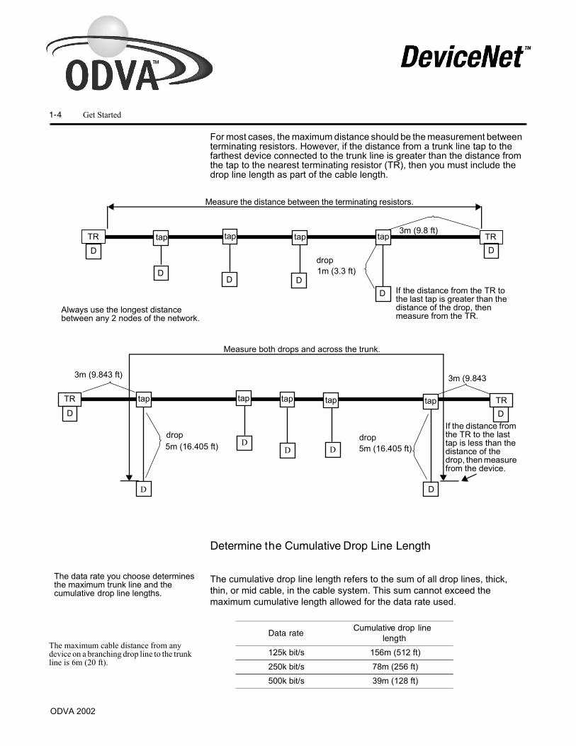
For most cases, the maximum distance should be the measurement between terminating resistors. However, if the distance from a trunk line tap to the farthest device connected to the trunk line is greater than the distance from the tap to the nearest terminating resistor (TR), then you must include the drop line length as part of the cable length.
Determine the Cumulative Drop Line Length
The cumulative drop line length refers to the sum of all drop lines, thick, thin, or mid cable, in the cable system. This sum cannot exceed the maximum cumulative length allowed for the data rate used.
TR
drop
If the distance from the TR to the last tap is greater than the distance of the drop, then measure from the TR.
3m (9.843
5m (16.405 ft)drop
TR
3m (9.8 ft)
1m (3.3 ft)
Measure both drops and across the trunk.
tap
3m (9.843 ft)
TR taptaptaptap
5m (16.405 ft)drop
Always use the longest distance between any 2 nodes of the network.
Measure the distance between the terminating resistors.
TR taptap
D
D
tap
DDD
D
If the distance from the TR to the last tap is less than the distance of the drop, then measure from the device.
DD
DD
D D
D
The data rate you choose determines the maximum trunk line and the cumulative drop line lengths.
Data rateCumulative drop line
length
125k bit/s 156m (512 ft)250k bit/s 78m (256 ft)500k bit/s 39m (128 ft)
The maximum cable distance from any device on a branching drop line to the trunk line is 6m (20 ft).
ODVA 2002
tap

Get Started 1-5
The following example uses four T-Port (single-port) taps and two multi-port taps to attach 13 devices to the trunk line. The cumulative drop line length is 42m (139 ft) and no single node is more than 6m (20 ft) from the trunk line. This allows you to use a data rate 125k bit/s. A data rate of 500k bit/s cannot be used in this example because the cumulative drop line length (42m) exceeds the total allowed (39m) for that data rate.
About the Direct Connection
Connect devices directly to the trunk line only if you can later remove the devices without disturbing communications on the cable system.This is called a “zero-length” drop, because it adds nothing (zero) when calculating cumulative drop line length.
TR TR
2m (6.6 ft)
3m(10 ft)
5m (16 ft) 4m
(13 ft)4m(13 ft)
2m(6.6 ft)4m (13 ft)
3m (10 ft)
3m(10 ft)2m(6.6 ft)
3m (102m (6.6
3m(10 ft)
Multiple-porttap (4 ports)
Multiple Port tap(8 ports)
= trunk line
= drop line
= device or node
TR = terminating resistor
1m(3.3 ft)
1m(3.3 ft)
Important: If a device provides only fixed-terminal blocks for its connection, you must connect it to the cable system by a drop line. Doing this allows you to remove the device at the tap without disturbing communications on the trunk line of the cable system.
device withremovable
open-styleconnector
device withfixedopen-styleconnector
ODVA 2002
))
of 250k bit/s or

1-6 Get Started
Using ConnectorsConnectors attach cables to devices or other components of the DeviceNetTM cable system. Field-installable connections are made with either sealed or open connectors.
Micro/Mini field-installable quick-disconnect (sealed) connectors (round media only).
Screw terminals connect the cable to the connector.
Plug-in field-installable (open) connectors
Most open-style devices ship with an open-style connector included.
See Chapter 3 for information about making cable connections
Connector Description
Sealed Mini-style: Attaches to taps and thick, thin, and mid cable.Micro-style: Attaches to thin cable only - has a reduced current rating.
Open Plug-in: Cable wires attach to a removable connector.Fixed: Cable wires attach directly to non-removable screw terminals (or equivalent) on device.
Wire Color
Wire Identity
Usage Round
UsageFlat
white CAN_H signal signal
blue CAN_L signal signal
bare drain shield n/a
black V- power power
red V+ power power
2
2
3
3
44
55
1
1
Micro Female Mini Female
mechanical key
mechanical key
drain
V+CAN_H
CAN_L
V-
CAN_L
CAN_Hdrain
V+ V-
jack screwjack screw
mechanical key
10-pin linear plug
mechanical key
5-pin linear plug
jack screwjack screw
drain CAN_HV+V-
drain CAN_HV+V-
probe holes
CAN_L
CAN_L
ODVA 2002

Get Started 1-7
The terminating resistor reduces reflections of the communication signals on the network. Choose your resistor based on the type of cable (round or flat) and connector (open or sealed) you use
� For round cable:
– the resistor may be sealed when the end node uses a sealed T-port tap
– the resistor may be open when the end node uses an open-style tap
� For flat cable:
– the resistor is a snap-on cap for the flat cable connector base, available in sealed and unsealed versions
You must attach a terminating resistor equal to 121 ohms, 1%, 1/4W or greater wattage, to each end of the trunk cable. You must connect these resistors directly across the blue and white wires of the DeviceNetTM cable.
The following terminating resistors provide connection to taps and the trunk line.
� sealed-style terminating resistors
Male or female connections attach to:
– trunk line ends
– T-Port taps
� open-style terminating resistors
121 ohms, 1%, 1/4W or greater wattage resistors connecting the white and blue conductors attach to:
– open-style T-Port taps
– trunk lines using terminator blocks
!ATTENTION: If you do not use terminating resistors as described, the DeviceNetTM cable system will not operate properly.
Terminate the network
TRTR2
To verify the resistor connection,disconnect power and measure the resistance across the Can_H and Can_L lines (blue and white wires, respectively). This reading should be approximately 50-60 ohms.
Do not put a terminating resistor on a node with a non-removable connector. If you do so, you risk network failure if you remove the node. You must put the resistor at the end of the trunk line.
ODVA 2002

1- 8 Get Started
� Flat cable terminating resistors
The 121 ohm resistor is contained in the snap-on interface module:
– sealed terminator with an Insulation Displacement Connector (IDC) base (NEMA 6P, 13; IP67)
– unsealed terminator with IDC base (no gaskets) (NEMA 1; IP60)
Network endcaps should be included with each flat cable terminator; see Page 3-12 for complete installation instructions.
Wire Color
Wire Identi ty
Usage Round
UsageFlat
white CAN_H signal signal
blue CAN_L signal signal
bare drain shield n/a
black V- power power
red V+ power power
CAN_L
V+V-
CAN_Hdrain
121 �
end capterminating resistor with end cap

Get Started 1-9
Guidelines for Supplying Power
The cable system requires the power supply to have a rise time of less than 250 milliseconds to within 5% of its rated output voltage. You should verify the following:
� the power supply has its own current limit protection
� fuse protection is provided for each segment of the cable system
– any section leading away from a power supply must have protection
� the power supply is sized correctly to provide each device with its required power
� derate the supply for temperature using the manufacturer’s guidelines
Appendix B - Powering Output Devices provides valuable information to the installer.
Choosing a Power Supply
The total of all of the following factors must not exceed 3.25% of the nominal 24V needed for a DeviceNetTM cable system.
initial power supply setting - 1.00%
line regulation - 0.30%
temperature drift - 0.60% (total)
- 1.05%
load regulation - 0.30%
Important:For class 2 cables, your national and local codes may not permit the full use of the power system capacity when installed as building wire. For example, in the United States and Canada, the power supplies that you use with class 2 cable must be Class 2 listed per the NEC and CECode. The total current allowable in any section of class 2 cable must not exceed 4A(100VA). Assume that a cable is class 2 unless the vendor describes it as class 1.
Class 1 power supplies allow for an 8A system, and the use of Class 1 flat cable. See Appendix A for more information about national and local codes.
powersupply Supply power3
!Use the power supply to power the DeviceNetTM cable system only. If a device requires a separate 24V power source other than the DeviceNetTM power source, you should use an additional 24V power source.
DNPS
Trunk drop
node powernode
time drift -
ODVA 2002

1-10 Get Started
Use a power supply that has current limit protection as per national codes such as NEC, Article 725.
If you use a single power supply, add the current requirements of all devices drawing power from the network. This is the minimum name-plate current rating that the power supply should have. For proper operation of your network, we recommend that you use a power supply that complies with the Open DeviceNet Vendor Association (ODVA) power supply specifications and NEC/CECode Class 2 characteristics (if applicable).
About Power Ratings
Although the round thick cable and Class 1 flat cable are both rated to 8A, the cable system can support a total load of more than 8A. For example, a 16A power supply located somewhere in the middle of the cable system can supply 8A to both sides of the power tap. It can handle very large loads as long as no more than 8A is drawn through any single segment of the trunk line. However, cable resistance may limit your application to less than 8A.
Drop lines, thick, mid or thin, are rated to a maximum of 3A, depending on length. The maximum current decreases as the drop line length increases.
You may also determine the maximum current in amps (I) by using:
I = 15/L, where L is the drop line length in feet
I = 4.57/L, where L is the drop line length in meters
Important:The dc output of all supplies must be isolated from the ac side of the power supply and the power supply case.
Drop line length Allowable current
1.5m (5 ft) 3A
2m (6.6 ft) 2A
3m (10 ft) 1.5A
4.5m (15 ft) 1A
6m (20 ft) 0.75A
To determine the required power supply current:1. Add the current requirements of
all devices drawing power from the network.For example: 6.3A
2. Add an additional 10% to this total to allow for current surge.e.g. 6.3A x 10% = 6.93A
3. Make sure the total of 2 is less than the minimum name-plate current of the power supply you are using.e.g. 6.3A < 8A and NEC/CECode
ODVA 2002

Get Started 1-11
The maximum allowable current applies to the sum of currents for all nodes on the drop line. As shown in the example on page Page 1-3, the drop line length refers to the maximum cable distance from any node to the trunk line, not the cumulative drop line length.
� The maximum allowable current may also be limited by high maximum common mode voltage drop on the V- and V+ conductors
– the voltage difference between any two points on the V- conductor must not exceed the maximum common mode voltage of 4.65V
voltage range between V- and V+ at each node within 11 to 25V
Sizing a Power Supply
Follow the example below to help determine the minimum continuous current rating of a power supply servicing a common section.
Power Supply 1
Add each device’s (D1, D2) DeviceNetTM current draw together for power supply 1 (1.50+1.05=2.55A).
2.55A is the minimum name-plate current rating that power supply 1 should have. Remember to consider any temperature or environmental derating recommended by the manufacturer.
powersupply 1
powersupply 2
152m(500 ft)
122m(400 ft)
122m(400 ft)
30m(100 ft)
30m(100 ft)
60m(200 ft)
TR TRPT PTT T T T T
D1 D2 D3 D4 D51.50A 1.05A 0.25A 1.00A 0.10A
TR = terminating resistor T = T-Port tapPT = power tap D = device break V+ (red wire) here to separate
both halves of the network
Important:This derating factor typically does not apply when you consider the maximum short circuit current allowed by the national and local codes.
Results
�
ODVA 2002

1-12 Get Started
Power Supply 2
Add each device’s (D3, D4, D5) current together for power supply 2 (0.25+1.00+0.10=1.35A).
1.35A is the minimum name-plate current rating that power supply 2 should have. Remember to consider any temperature or environmental derating recommended by the manufacturer.
Placing the Power Supply
DeviceNetTM networks with long trunk lines or with devices on them that draw large currents at a long distance sometimes experience difficulty with common mode voltage. If the voltage on the black V- conductor differs by more than 4.65 volts within the trunk line from one point on the network to another, communication problems can occur. Note: There is 0.35 volts reserved for the drop line. Moreover, if the voltage between the black V- conductor and the red V+ conductor ever falls below 15 volts, then common mode voltage could adversely affect network communication. To work around these difficulties, add an additional power supply or move an existing power supply closer to the heavier current loads.
To determine if you have adequate power for the devices in your cable system, use the look-up method which we describe more fully in Chapter 4. See the following example and figure (other examples follow in Chapter 4). You have enough power if the total load does not exceed the value shown by the curve or the table.In a worst-case scenario, all of the nodes are together at one end of the cable and the power supply is at the opposite end, so all current flows over the longest distance.
A sample curve (reprinted from page 4-4) for a single, end-connected power supply is shown on the next page.
Important:This method may underestimate the capacity of your network by as much as 4 to 1. See Chapter 4 to use the full-calculation method if your supply does not fit under the curve.
Results
PowerSupply
Nodes
ODVA 2002

Get Started 1-13
Figure 1.1 One Power Supply (End Segment) Flat Cable
Important:Assumes all nodes are at the opposite end of the cable from the power supply.
Cur
rent
(am
pere
s)
Length of trunk line, meters (feet)
NEC/CE Code MaximumCurrent Limit
See Appendix A
Network Lengthm (ft)
Maximum Current (A)
0 (0) 8.00*
20 (66) 8.00*
40 (131) 7.01*
60 (197) 4.72*
80 (262) 3.56
100 (328) 2.86
120 (394) 2.39
140 (459) 2.05
160 (525) 1.79
180 (591) 1.60
200 (656) 1.44
Network Lengthm (ft)
Maximum Current (A)
220 (722) 1.31
240 (787) 1.20
260 (853) 1.11
280 (919) 1.03
300 (984) 0.96
320 (1050) 0.90
340 (1115) 0.85
360 (1181) 0.80
380 (1247) 0.76
400 (1312) 0.72
420 (1378) 0.69
� Exceeds NEC CL2/CECode 4A
ODVA 2002

1-14 Get Started
The following example uses the look-up method to determine the configuration for one end-connected power supply. One end-connected power supply provides as much as 8A near the power supply.
1. Determine the total length of the network.
– 106m
2. Add each device’s current together to find the total current consumption.
– 0.10+0.15+0.30+0.10=0.65A
3. Find the next largest network length using the table on page 1-13 to determine the maximum current allowed for the system (approximately).
– 120m (2.47A)
Since the total current does not exceed the maximum allowable current, the system will operate properly (0.65A is less than 2.47A).
� Do the full-calculation method described in Chapter 4.
� Move the power supply to somewhere in the middle of the cable system and reevaluate per the previous section.
powersupply
TR PT
D1 D2 D3 D40.10A 0.15A 0.30A 0.10A
m(75
m(100
53m(175
106m(350 ft)
TR = terminating resistor T = T-Port tapPT = power tap D = device
T
powersupply
TR TRPT T T
D1 D2 D3 D40.10A 0.1 5A 0.30A 0.10A
23m(75 ft)
30m(100 ft)
53m(175 ft)
106m(350 ft)
TR = terminating resistor T = T-Port tapPT = power tap D = device
T
Important: Make sure that the required power is less than the rating of the power supply. You may need to derate the supply if it is in an enclosure.
Important:If your application doesn’t fit “under the curve,” you may either:
Results
ODVA 2002
T

Get Started 1-15
Connecting Power Supplies
To supply power you will need to install and ground the power supplies. To install a power supply:
1. Mount the power supply securely allowing for proper ventilation, connection to the ac power source, and protection from environmental conditions according to the specifications for the supply.
2. Connect the power supply using:
– a cable that has one pair of 12 AWG (4 mm2)* conductors or the equivalent or two pairs of 15 AWG (2.5mm2) conductors
– a maximum cable length of 3m (10 ft) to the power tap
– the manufacturer’s recommendations for connecting the cable to the supply
* NOTE: Metric wire sizes are for reference only - you should select a wire size big enough for the maximum possible current.
Important:Make sure the ac power source remains off during installation.
ODVA 2002

1-16 Get Started
You must ground the DeviceNetTM network at only one location. Follow the guidelines described below.
To ground the network:
� Connect the network shield and drain wire to an good earth or building ground (such as an 8 foot stake driven into the ground, attached to building iron or the cold water plumbing) using a 25 mm (1 in.) copper braid or a #8 AWG (10 mm2) wire up to 3m (10 ft) maximum in length.
� Use the same ground for the V- conductor of the cable system and the chassis ground of the power supply. Do this at the power supply.
!ATTENTION: To prevent ground loops,
– For Shielded Round media - Ground the V- conductor, shield, and drain wire at only one place.
– For Flat media - Ground the V- conductor at only one place.
Do this at the power supply connection that is closest to the physical center of the network to maximize the performance and minimize the effect of outside noise.
Make this grounding connection using a 1 in (25mm) copper braid or a #8 AWG (10mm2) wire up to a maximum 3m (10 ft) in length. Where greater than 3M (10 ft) must be used due to installation constraints, adequate sized grounding cable shall be utilized to ensure dffective grounding takes place and provides a low impedance path from the shield to ground for optimal shield performance.
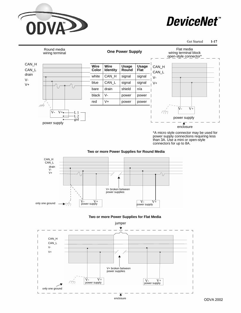
If you use more than one power supply, the V- conductor of only one power supply should be attached to an earth ground.
If you connect multiple power supplies, V+ should be broken between the power supplies. Each power supply’s chassis should be connected to the common earth ground. Verify that V- is isolated from the Power supply chassis.
Important: For a non-isolated device, be certain that additional network grounding does not occur when you mount the device or make external connections to it. Check the device manufacturer’s instructions carefully for grounding information.
Ground the Network
powersupply4
ODVA 2002
Get Started 1-17
ODVA 2002
Round mediawiring terminal
CAN_HCAN_LdrainV-V+
V- V+ L 1L 2grd
power supply power supplyV+V- V- V+
CAN_HCAN_L
drain
V+V-
only one ground
One Power Supply
Two or more Power Supplies for Round Media
Flat mediawiring terminal block
open-style connector*
CAN_HCAN_LV-
V- V+
V+
V+ broken between power supplies
power supply
Two or more Power Supplies for Flat Media
only one ground
V+ broken between power supplies
V+V-
CAN_HCAN_L
V+V-
power supplypower supply
power supply
*A micro style connector may be used for power supply connections requiring less than 3A. Use a mini or open-style connectors for up to 8A.
enclosure
jumper
enclosure
Wire Color
Wire Identity
Usage Round
UsageFlat
white CAN_H signal signal
blue CAN_L signal signal
bare drain shield n/a
black V- power power
red V+ power power
V+V-
Get Started 1-17

1-18 Get Started
Use this checklist when you install the DeviceNetTM network. You should complete this checklist prior to applying power to your network.
Total device network current draw does not exceed power supply current limit.Common mode voltage drop does not exceed limit (as defined in Section 3, Chapter 1).Number of DeviceNetTM nodes does not exceed 64 on onenetwork. The practical limit on DeviceNetTM nodes maybe 61 slave nodes since you should allow one node each for the scanner, the computer interface module, and an open node at node 63.*No single drop over 6m (20 ft).Cumulative drop line budget does not exceed network baud rate limit.Total network trunk length does not exceed the maximum allowable per the network data rate and cable type.Terminating resistors are on each end of the trunk line and are proper.Ground, at only one location, preferably in the center of the network
– V- for flat media
– V- drain and shield for round media
All connections are inspected for loose wires or coupling nuts.Check for opens and shorts.
Important: * Devices default to node 63. Leave node 63 open to avoid duplicate node addresses when adding devices. Change the default node address after installation.
Use the checklist5
ODVA 2002

Chapter 2Identify Cable System ComponentsUse this chapter to identify and become familiar with the basic DeviceNet cable system components.
ODVA 2002
sealed device
sealed deviceterminator
T-port tap
thick cable
multi port tap(8 port)
terminatorT-port tap
thin cableMulti porttap (4 port)
thick cable
open-style tap
sealed device
powertap
Round (Thick, Mid and Thin) Cable Network
Flat Cable Network
open-style modules
Open styleconnector
module
powersupply
open-style
terminatorPLC
enclosure
flat trunk cable micro
connector
terminator
enclosure
thick cable
open-style device
powersupplypowersupply
2-2 Identify Cable System Components
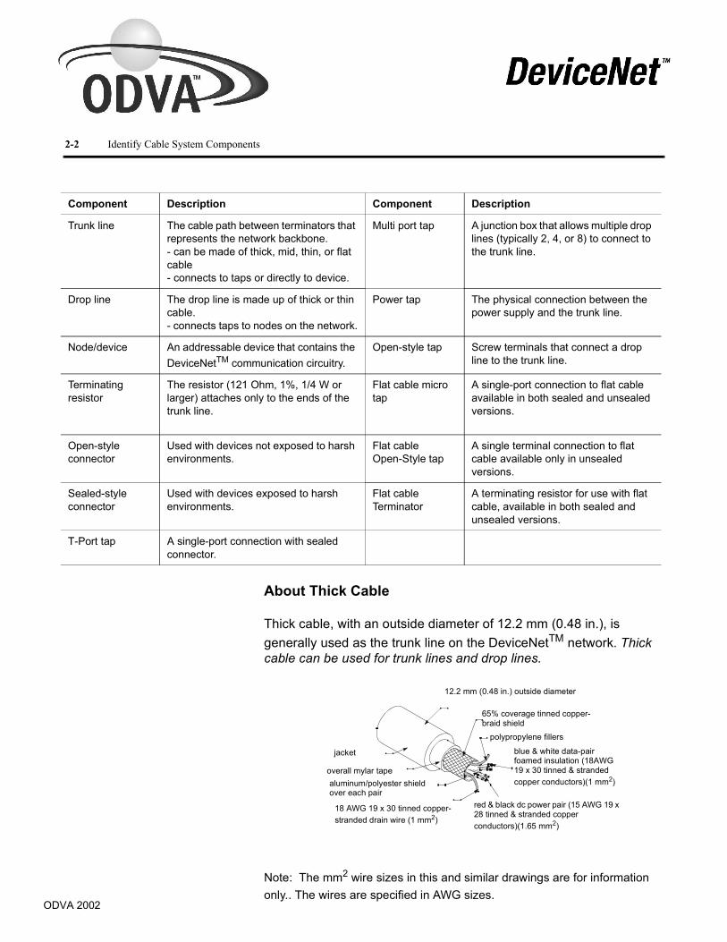
About Thick Cable
Thick cable, with an outside diameter of 12.2 mm (0.48 in.), is generally used as the trunk line on the DeviceNetTM network. Thick cable can be used for trunk lines and drop lines.
Note: The mm2 wire sizes in this and similar drawings are for information only.. The wires are specified in AWG sizes.
Component Description Component Description
Trunk line The cable path between terminators that represents the network backbone.- can be made of thick, mid, thin, or flat cable- connects to taps or directly to device.
Multi port tap A junction box that allows multiple drop lines (typically 2, 4, or 8) to connect to the trunk line.
Drop line The drop line is made up of thick or thin cable.- connects taps to nodes on the network.
Power tap The physical connection between the power supply and the trunk line.
Node/device An addressable device that contains the DeviceNetTM communication circuitry.
Open-style tap Screw terminals that connect a drop line to the trunk line.
Terminating resistor
The resistor (121 Ohm, 1%, 1/4 W or larger) attaches only to the ends of the trunk line.
Flat cable micro tap
A single-port connection to flat cable available in both sealed and unsealed versions.
Open-style connector
Used with devices not exposed to harsh environments.
Flat cable Open-Style tap
A single terminal connection to flat cable available only in unsealed versions.
Sealed-style connector
Used with devices exposed to harsh environments.
Flat cable Terminator
A terminating resistor for use with flat cable, available in both sealed and unsealed versions.
T-Port tap A single-port connection with sealed connector.
jacket
overall mylar tapealuminum/polyester shieldover each pair
18 AWG 19 x 30 tinned copper-stranded drain wire (1 mm2)
12.2 mm (0.48 in.) outside diameter
65% coverage tinned copper-braid shield
polypropylene fillers
blue & white data-pairfoamed insulation (18AWG 19 x 30 tinned & stranded copper conductors)(1 mm2)
red & black dc power pair (15 AWG 19 x 28 tinned & stranded copperconductors)(1.65 mm2)
ODVA 2002
Identify Cable System Components 2-3
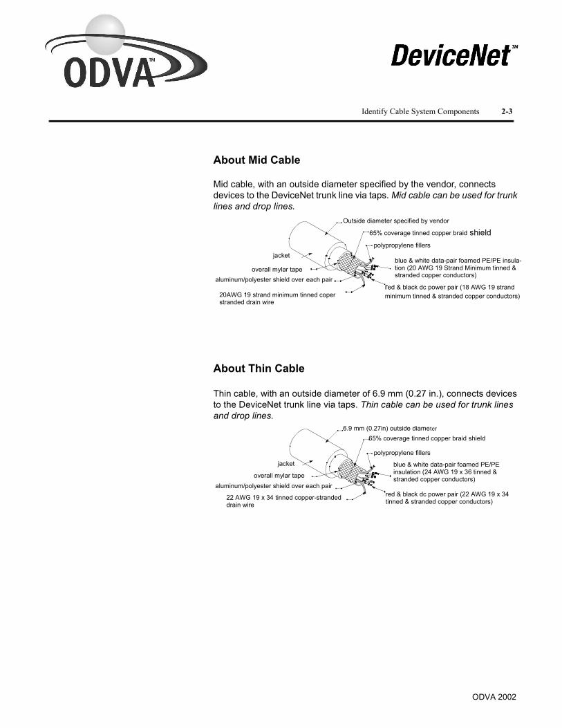
About Mid Cable
Mid cable, with an outside diameter specified by the vendor, connects devices to the DeviceNet trunk line via taps. Mid cable can be used for trunk lines and drop lines.
About Thin Cable
Thin cable, with an outside diameter of 6.9 mm (0.27 in.), connects devices to the DeviceNet trunk line via taps. Thin cable can be used for trunk lines and drop lines.
jacket
overall mylar tapealuminum/polyester shield over each pair
Outside diameter specified by vendor
65% coverage tinned copper braid shield
blue & white data-pair foamed PE/PE insula-tion (20 AWG 19 Strand Minimum tinned & stranded copper conductors)
polypropylene fillers
red & black dc power pair (18 AWG 19 strand minimum tinned & stranded copper conductors)20AWG 19 strand minimum tinned coper
stranded drain wire
jacket
overall mylar tapealuminum/polyester shield over each pair
22 AWG 19 x 34 tinned copper-stranded drain wire
6.9 mm (0.27in) outside diameter65% coverage tinned copper braid shield
blue & white data-pair foamed PE/PEinsulation (24 AWG 19 x 36 tinned &stranded copper conductors)
polypropylene fillers
red & black dc power pair (22 AWG 19 x 34 tinned & stranded copper conductors)
ODVA 2002

2-4 Identify Cable System Components
About Flat Cable
Flat cable is physically keyed to prevent wiring mishaps. Flat cable is unshielded and contains four conductors. Flat cable is usually used only for the trunk line.
It is common practice to use a second flat cable to power outputs, e.g. valves, actuators or indicators. This is called the Auxiliary Power Cable. It is typically distinguished from the DeviceNetTM by jacket color: typically black for Auxiliary Power, typically gray for DeviceNetTM .
Connecting to the Trunk Line
The cable system design allows you to replace a device without disturbing the cable system’s operation.
dc power pair 16 AWG (1.5 mm2)
5.3 mm(0.21 in.)
jacket material:Device NetTM - typically grayAuxiliary Power: typically black
2.50 mm(0.10 in.)
data pair 16 AWG (1.5 mm2)19.3 mm (0.76 in.)
red black
bluewhite
Important: You must terminate the trunk line on each end with a 121 Ohm, 1%, 1/4W resistor.
ODVA 2002

Identify Cable System Components 2-5
You can connect to the trunk line through a:
Trunk-line connection See page Trunk-line connection See page• T-Port tap 2-6 • Multi port tap 2-7
• Power tap 2-7 • Multi port tap 2-8
• Open-style connector 2-9 � Open-style tap 2-9
• Flat cable open-style connector 2-10 • Flat cable micro connector 2-10
41866 41867
powersupply
4186841869
41679
ODVA 2002

2-6 Identify Cable System Components
About the T-Port Tap
The T-Port tap connects to the drop line with a mini or micro quick-disconnect style connector. Mini T-Port taps provide right or left keyway for positioning purposes. Mini T-Ports are also available with a micro (M12) drop connection .
Mini T-Port tap
Micro T-Port tap
Female ConnectorEnd View
Male ConnectorEnd View
CAN_H
CAN_H
CAN_H
CAN_H
CAN_L
CAN_L
CAN_L
CAN-Ldrain
drain
drain
drain
V+
V+
V+
V+
V-
V- V-
V-
Keying Information Right keyway Left keyway
maleconnector
30428-M
3 4
5
2 1
3 4
5
2 1
Male (pins) Female (sockets)
1 - Drain2 - V+3 - V-4 - CAN_H5 - CAN_L
bareredblackwhiteblue
femaleconnectors
ODVA 2002

Identify Cable System Components 2-7
About the Multi Port Tap
Multi port taps use round media only for a direct connection to a trunk line. They provide terminal strip connections for as many as 8 nodes using thin-cable drop lines. Removable gasket covers and cable glands provide a tight, sealed box that you can mount on a machine. Order Multi port taps according to the trunk type (thick, mid or thin).
About the Power tap
The power tap can provide overcurrent protection to the cable, with fuses for each trunk. (Country and/or local codes may prohibit the use of the full capacity of the tap.) You can also use the power tap to connect multiple power supplies to the trunk line without back-feeding between supplies by removing one of the fuses. Power taps are only used with round media.
In cases in which the power supply provides current limiting and inherent protection, you may not need fuses/overcurrent devices at the tap.
Power tap schematic
sub-assembly PCB
cable grips
enclosure
CAN_LbareV-V+
V- V+
Wire Color
Wire identity
Use
white CAN_H signal
blue CAN_L signal
bare drain shield
black V- power
red V+ power
CAN_H
power supply
Schematic CAN_H CAN_L Bare
V- V+
Schottky Diode
Fuse Fuse
Network Supply
GND
V- V+
2-Port Multi port Tap 4-Port Multi port Tap 8-Port Multi port Tap
ODVA 2002

2-8 Identify Cable System Components
About the Multi Port Tap
Multi port taps connect to a round or flat media trunk line via drop lines. Multi ports connect multiple devices to the network through mini or micro quick disconnects. The ports of the multi port taps provide connectivity to the network for multiple nodes at one location.
Micro Version
All device connections are micro female receptacles; only micro male connectors with rotating coupling nuts can interface with each port.
Mini multi port taps
All device connections in the multi port tap are mini female receptacles; only mini male connectors can interface with each port. Trunk connection is a mini male quick disconnect.
5-pin fixed internal
thin cable
Multi port Tap with 2m Drop Line
5-Pin mini female connectorsJ1 J2 J3 J4
J5 J6 J7 J8
5-pin mini maleconnector
ODVA 2002

Identify Cable System Components 2-9
About the Direct Connection
Connect devices directly to the trunk line only if you can later remove the devices without disturbing communications on the cable system.
About the Open-Style Connector
Open-style connectors come in two primary varieties:
� five-position (5-pin linear plug)
� ten-position (10-pin linear plug)
Ten-position connectors provide easier daisy-chaining because there is an independent wire chamber for each wire (entering cable and exiting cable).
Some open-style connectors provide a temporary connection, for a PC or other configurable tool, using probe holes. For connection, insert the prongs of a probe cable into the probe holes of aconnector. Mechanical keys on the connector prevent improper insertion.
Important:If a device provides only fixed-terminal blocks for its connection, you must connect it to the cable system by a drop line. Doing this allows you to remove the device at the tap without disrupting communications on the cable system.
device withfixedopen-styleconnector
trunk line
disconnecthere
drop line
Wire Color
Wire Identity
Usage Round
white CAN_H signalblue CAN_L signal
bare drain shield
black V- powerred V+ power
genericunsealeddevice
probe cable
to PC
See troubleshooting guide for details.
ODVA 2002
open-style connectors
5-pin linear plug (open)
jack screwjack screw
BlueShield or Bare WhiteRedBlack
jack screwjack screw
mechanical key
10-pin linear plug (open)
mechanical key
Blue Shield or Bare WhiteRedBlack
probe holes
prong
probe holes
insert probe cable into probe holes of connector
mechanical key

2-10 Identify Cable System Components
About Flat Cable Insulation Displacement Connectors (IDCs)
IDCs interface drop cables and devices to the flat cable trunkline. The hinged, two-piece base snaps around the flat cable at any point along the trunk. Contact is made with the cable conductors by tightening two screws that drive the contacts through the cable jacket and into the conductors. The snap-on interface provides the connection to the drop cable and is available with various connectors.
V+ V-
CAN_HCAN_L
Open - Style Micro
ODVA 2002

Identify Cable System Components 2-11
Using Preterminated Cables
Using preterminated cable assemblies saves you the effort of stripping and wiring connectors to the cable ends and also reduces wiring errors as these cable assemblies are normally factory tested.
About Thick Cable
You can order preterminated thick cable in several lengths with mini connectors at each end. Thick cable that is 6m (20ft) or shorter can also be used as drop lines.
insert probe cable into probe holes of connector
mechanical key
Preterminated thin cable assemblies for use as a drop line are available with various connectors in several lengths. Preterminated thin cable assemblies can also be used as trunk lines up to a total of 100 meters in a system.
Connecting to a T-port tap from a sealed device.
insert probe cable into probe holes of connector
mechanical key
mini T-Port male plug
specified length
rotatingcouplingnut
rotating couplingnut
thick cable
female plug
thick cable
mini T-Port
specified length
specified lengthmale plug female plug
device
device
T-port tap
T-port tap
male plug female plugspecified length
ODVA 2002
About Thin Cable

2-12 Identify Cable System Components
Connecting to a T-Port tap from an open device
Connecting to a multi port tap or Micro T-Port tap from a sealed device
Connecting to a multi port tap or open-style tap from a sealed device
male plug female plugspecified length
thin cable
device
to multi port tap, or micro T-Port tap
to multi port tap, or micro T-Port tap
male plug female plug
thin cable
specified length
device
to multi port tap
to multi port tap
thin cable
thin cable
female plug
female plug
specified length
specified length
device
device
conductors (pigtails)
Stripped conductors (pigtails)
ODVA 2002
ed cppStri

Identify Cable System Components 2-13
Connecting to micro T-Port taps
Connecting to a flat cable tap from a sealed device
About T erminators
Electrically stabilize your DeviceNetTM communication with terminating resistors.
thin cable
specified length
trunk line
drop lines
devicedevice
to flat cable Micro
to flat cable Micro
male plug female plugspecified length
thin cable
device
male plug female plug
thin cable
specified lengthdevice
Important: You must terminate the trunk line on each end with a 121ohms, 1%, 1/4W resistor.
Wire Color
Wire Identity
Usage Round
UsageFlat
white CAN_H signal signal
blue CAN_L signal signalbare drain shield n/a
black V- power power
red V+ power power
ODVA 2002

2-14 Identify Cable System Components
Sealed-style terminators (round media)
Male and female sealed terminators are available in mini and micro versions.
Unsealed-Style terminator (round and flat media)
An open-style terminator is suitable for use with:
� Multi-port taps (open style taps only)� open-style plugs or taps� Flat cable open-style Insulation Displacement Connectors (IDC)
Sealed and unsealed flat media terminators
These terminators have an IDC base and are shipped with an end cap. Unsealed terminators do not have gaskets.
Mini-male terminator
Mini-female terminator
Important: You must connect these resistors directly across the blue and white wires of the DeviceNetTM cable.
121ohms Flat cable IDC with open-style terminator
end cap
A means of sealing aflat cable connector.
ODVA 2002

Chapter 3
Make Cable Connections
Preparing Cables In Chapter 1, you determined the required lengths of trunk line and drop line segments for your network. To cut these segments from reels of thick, thin, mid and flat cable, use a sharp cable cutter and provide sufficient length in each segment to reduce tension at the connector.
Select an end of the cable segment that has been cleanly cut. The positions of the color-coded conductors should match the positions at the face of the connector.
Important: Before beginning, make sure:� the DeviceNet cable system is inactive� all attached devices are turned off� any attached power supply is turned off� you follow the manufacturer’s instructions for stripping,
crimping, and/or tightening
The dimensions and instructions in this chapter are typical formany connectors. Some connectors are different. Follow theconnector manufacturer’s instructions if they differ from thosein this chapter.
ODVA 2002

ODVA 2002
3-2 Make Cable Connections
How to Install Open-Style Connectors
To attach a plug-in open-style connector to a round media (thick, mid or thin) trunk line:
1. Strip 65 mm (2.6 in.) to 75 mm (3 in.) of the outer jacket from the end of the cable, leaving no more than 6.4 mm (0.25 in.) of the braided shield exposed.
2. Wrap the end of the cable with 38 mm (1.5 in.) of shrink wrap, covering part of the exposed conductors and part of the trunk line insulation.
3. Strip 8.1 mm (0.32 in.) of the insulation from the end of each of the insulated conductors.
4. Tin the last 6.5 mm (0.26 in.) of the bare conductors or crimp a suitable ferrule on the conductors.
5. Insert each conductor into the appropriate clamping cavity of the open-style connector or the screw terminal on the device, according to the color of the cable insulation.
6. Tighten the clamping screws to secure each conductor. The male contacts of the device connector must match the female contacts of the connector.
jacket
6.4 mm(0.25 in.)
65 mm(2.6 in.)
braided shield
jacket
38 mm(1.5 in.)
shrink wrap
shrink wrap
jacket
8.1 mm(0.32 in.)
clamping
open-style connector(female connector)
open-style receptacle(male contacts)
open-style connector(female contacts)
redwhitebareblue
black
redwhitebareblueblack
black
blue bare white
red
Wire Color
Wire Identity
Usage Round
white CAN_H signalblue CAN_L signal
bare drain shield
black V- powerred V+ power

ODVA 2002
Make Cable Connections 3-3
How to Install Mini/Micro Sealed Field-Installable Connectors
To attach a mini/micro sealed-style connector to round media:
1. Prepare the cable jacket by cleaning loose particles from the jacket.
2. Strip 30 mm (1.2 in.) of the cable jacket from the end of the cable.
3. Cut the braided shield and the foil shields surroundingthe power and signal conductors.
4. Trim the conductors to the same length.
5. Slide the connector hardware onto the cable in the order shown.
6. Strip 10 mm (0.4 in.) of insulation from the ends of all conductors except the bare drain wire.
7. Attach wires to the connector using screw terminals as seen in the following diagram.
8. Screw the enclosure body to the connector.
9. Screw the rear nut into the connector enclosure.
Important: Do not twist or pull the cable while tightening the gland nut.
Important: Do not twist or pull the cable while tightening the rear nut.
jacket
70mm(2.75 in.)
clean jacket30 mm(1.2 in.)
rear nutgrommet enclosure
slide hardware
bevelled Do not nick theconductor strands.
rubber washer
9 mm(0.374 in.)
Wire Color
Wire identity
Usage Round
white CAN_H signal
blue CAN_L signal
bare drain shieldblack V- power
red V+ power
Mini male connector Mini female connector
power conductors power conductors
signalconductors
signal conductors
bare bare
blackwhitered
bare blue
blackredwhite
blue bareRear View Rear View

ODVA 2002
3-4 Make Cable Connections
How to Install Power Taps and Multi Port Taps with Terminals
Cable preparation and attachment is the same for Power taps and Multi Port taps which use hard-wire connections of round media. To install your taps, perform the following steps and then proceed to the appropriate section for wiring the specific tap.
1. Remove the cover from the tap.
2. Prepare the ends of the cable sections.
A. Strip 65 mm (2.6 in.) to 76 mm (3 in.) of the outer jacket
and braided shield from the end of the cable.
– Leave no more than 6.4 mm (0.25 in.) of the braided shield exposed.
B. Strip 8.1 mm (0.32 in.) of the insulation from the end of each of the insulated conductors.
3. Attach cables to the enclosure.
4. Insert conductors into the terminal block clamping cavities, following the color coding specified for the terminal blocks.
jacket
76 mm(3 in.)
6.4 mm(0.25 in.)
braided shield
8.1 mm(0.32 in.)
heat shrink
Wire Color
Wire identity
Use
white CAN_H signal
blue CAN_L signal
bare drain shieldblack V- power
red V+ powerred
redwhitedrainblueblack
blackbluedrainwhitered
blackbluedrainwhiteredblackbluedrainwhitered black
bluedrainwhitered
blackbluedrainwhiteredblack
bluedrainwhite
redwhitedrainblue
black
thick cable terminal blocks
red
red
whi
te
whi
tedr
ain
drai
nbl
ue
blue
blac
k
blac
k
trunk line(thick cable)
trunk line(thick cable)
drop lines(thin cable)
drop lines(thin cable)
plugand nut
plug and nut
locking nuthex flange
gland nut
thin cable terminal blocks

ODVA 2002
Make Cable Connections 3-5
5. Tighten all clamping screws to secure conductors to the terminal blocks.
6. Seal unused ports.
7. Tightly secure the cover to the enclosure.
How to Install Multi Port Taps with Sealed Connectors
The Multi Port tap connects multiple quick-disconnect cables to the trunk line.
To Connect Drop Lines
Drop lines, made up of thick, mid or thin cable, connect devices to taps. Connections at the device can be:
� open-style
– pluggable screw connectors
– hard-wired screw terminals– soldered
� sealed-style
– mini quick-disconnect connectors– micro quick-disconnect connectors
J1 J2 J3 J4
J8J7J6J5Cable
Important: It is best to connect drop lines when the cable system is inactive. If you must connect to an active cable system, make all other connections before the connection to the trunk line.
!ATTENTION: Although it is possible to make a screw-terminal connection while the cable network is active, you should avoid this if at all possible.
When installing Multi Port Taps or removing nodes for maintenance it isimportant to seal unused ports to maintain the integrity of the IP rating of the installation. Use suitable threaded plugs to seal unusedconnectors
ODVA 2002
3-6 Make Cable Connections
To connect drop lines:
1. Attach contacts as described earlier in this section.
2. Connect the cable to the device.
3. Make any intermediate connections.
4. Make the connection to the trunk line last
5. Add and record measured drop length on cabling documentation.
Flat Cable Installation Instructions
How to Install a Flat Cable Connector
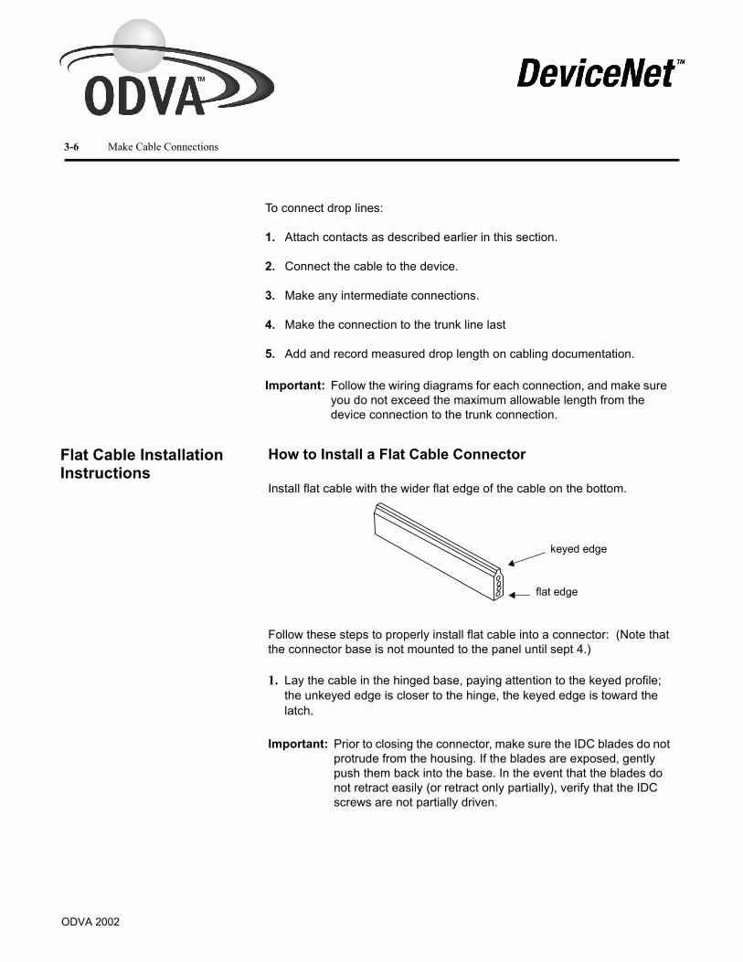
Install flat cable with the wider flat edge of the cable on the bottom.
Follow these steps to properly install flat cable into a connector: (Note that the connector base is not mounted to the panel until sept 4.)
1. Lay the cable in the hinged base, paying attention to the keyed profile; the unkeyed edge is closer to the hinge, the keyed edge is toward the latch.
Important: Follow the wiring diagrams for each connection, and make sure you do not exceed the maximum allowable length from the device connection to the trunk connection.
Important: Prior to closing the connector, make sure the IDC blades do not protrude from the housing. If the blades are exposed, gently push them back into the base. In the event that the blades do not retract easily (or retract only partially), verify that the IDC screws are not partially driven.
flat edge
keyed edge

ODVA 2002
2. Close the hinged assembly, applying pressure until the latch locks into place.The latch has two catches. The first catch loosely holds the connector on the cable. The second catch needs more pressure applied to close the connector tightly. If the cable is not in the correct position, the connector will not close.
keyed edge is toward the latch
latch
Make Cable Connections 3-7

ODVA 2002
3-8 Make Cable Connections
3. Make sure the cable is straight before moving on to step four.
the metal inserts.
5. Drive the IDC contacts into the cable by tightening down the two screws in the center of the base assembly. Once again, be careful to avoid stripping, ample but not excessive torque should be used.
!ATTENTION: You must make sure the cable is straight before tightening the screws. Improper seating of the cable may cause a weak seal and impede IP67 requirements for the life of the cable. A misaligned cable may also cause shorts due to mis-registration of the IDC contacts.
Tighten screws by the latch first
Check the cable position prior to tightening the screws.
The module should not be removed after connection is made. Determine the exact placement of the connector before engaging the IDC contacts.
!ATTENTION: Once the IDC contacts are driven into the cable, the module should not be removed. If the module is removed, it must be discarded and proper cable healing techniques must be used to protect the waterproofing to IP67.
4. Tighten down the two screws at the center points of the hinge and latchsides of the base; tighten down the latch side first. Take care to avoid stripping, ample torque per manufacturers specifications. Mount the base to the panel by driving screws through the corner holes not contining the metalinserts.

ODVA 2002
Make Cable Connections 3-9
6. Line up the keyed rectangular holes of the micro/open/terminator/other connection interface with the matching posts on the base and snap the connection interface into place. Optional: Secure the micro/open/terminator module by driving screws through the two remaining mounting holes.
Additional considerations: When used in flexing applications, the cable must be secured to a solid reference with mounting hardware 10-15 cm (4-6 in.) from the connector.
� Installation of connectors is recommended only at temperatures of 0°C - 75°C.
� Make sure the cable is free of debris or scratches before attaching the connector to ensure a proper seal.
� The recommended distance between cable mounts is 3-5 m (10-16 ft) .� Special glands are available for running cable into an enclosure.
Installing a flat cable open-style connector to a drop cable
Install the flat cable open-style connector to the flat media using the directions starting on page 3-6. Prepare the drop cable following the directions on page 3-2 numbers 1 through 5. For flat media connections you can use shielded or unshielded drop cables
– You must cut or heat shrink the drain wire when you use shielded drop cable.
two remaining mounting holes
red white blue black red white blue black
Theunshielded drop cable has no drain wire.
To use shielded drop cable, bend back and heat shrink, or cut, the drain wire.
Wire Color
Wire identity
Use Flat
white CAN_H signal signal
blue CAN_L signal signal
bare drain shield n/ablack V- power power
red V+ power power

ODVA 2002
3-10 Make Cable Connections
End Cap Installation
Each flat cable terminator module needs an end cap designed to cover the exposed end of the cable. To install the end cap:
1. Fit the end cap on the cable as keyed. Align the end cap posts with the receptacles in the lower IDC base and press down until the end cap is firmly seated (the upper surface of the posts will be flush with the upper surface of the base).
2. Close the IDC base and continue with the connection process..
When installing an end cap on the other end of the cable, note that the guide receptacles are on the upper portion of the IDC base. Repeat the end cap installation process as outlined previously. Close the IDC base and continue with connection. .
Align the end cap posts with receptacles in the base.
End Cap

ODVA 2002
Make Cable Connections 3-11
Installing Auxiliary Power Cable
Install Auxiliary Power Cable as you would network cable. Refer to page 3-6 for installation instructions..
Pinout diagrams for micro and mini connections to the power cable are shown next.
Connecting Power Supplies to Round Media
To supply power you will need to install and ground the power supplies as well as connect all Power taps.If you haven’t determined power supply placement, see Chapter 4. To install a power supply:
1. Mount the power supply securely allowing for proper ventilation, connection to the ac power source, and protection from environmental conditions according to the specifications for the supply.
2. Connect the power supply using:
� a cable that has one pair of 12 AWG (3.3mm2) conductors or the equivalent or two pairs of 15 AWG (1.7mm2) conductors
� a maximum cable length of 3m (10 ft) to the Power tap
� the manufacturer’s recommendations for connecting the cable to the supply
Wire Color
Wire identity
Use
white user defined
user defined
blue user defined
user defined
black V- output power
red V+ output power
Auxiliary Power Cable
jacket
red and blackdc power pair 16 awg (1.5 mm2)
white and blueuser defined pair 16 awg (1.5 mm2)
5.3 mm(0.21 in.)
19.3 mm(0.76 in.)
2.50 mm(0.10 in.)
When running cable into an enclosure, use a flat cable gland.
2
2
3
3
44
55
1
1
Micro Female Mini Female
mechanical key
mechanical keynot used
V+user defined
user defined
V-
user defined
user definednot used
V+ V-
Important: Make sure the ac power source remains off during installation.

ODVA 2002
3-12 Make Cable Connections
Connecting Power Supplies to Flat Cable
Use a flat cable tap to connect power. Choose a tap that is suitable for the expected current.
Because these taps have no overcurrent protection, you must provide such protection (fuse or circuit breaker) externaly or use a current-limited power supply.
Only connect V+ (red) and V- (black) unless the power supply is designed for use with DeviceNetTM and requires all conductors. If you use a molded connector that includes the other conductors CAN_H (white) and CAN_L (blue) ensure these are not connected at the power supply. Cut and insulate them. Their length must be included in the cumulative drop length calculation.

Chapter 4
Determine Power Requirements
In this chapter, we describe two methods for determining your system’s power requirements:
� the look-up method
� the full-calculation method
Try the look-up method first, then move on to the full-calculation method if you cannot meet your configuration requirements.
To determine if you have adequate power for the devices in your cable system, see the following examples and figures. You have enough power if the total load does not exceed the value shown by the curve or the table.
In a worst-case scenario, all of the nodes are together at the opposite end of the cable from the power supply.
Important: You must consider two areas when powering output devices using the DeviceNetTM power supply:
� (1) Wide DeviceNetTM voltage range of 11-25V dc
� (2) Noise or transient protection at each device
You must calculate a worst-case situation, and maintain voltage within the 11-25V dc range on all segments. This can be accomplished using diodes or other similar techniques. See Appendix B, Powering Output Devices, for more information.
Use the Look-UP Method
Power Supply
Nodes
ODVA 2002

ODVA 2002
4-2 Determine Power Requirements
Important: This method may underestimate the capacity of your network by as much as 4 to 1. See the following section to use the full-calculation method if your supply does not fit under the curve.
For this configuration example
Flat cable uses figure
Thick cable uses figure
Mid cable usesfigure
Thin cable uses figure
One power supply (end-connected)
Figure 4.2
Figure 4.1
Figure4.7
Figure 4.8
One power supply (middle-connected)
Figure 4.2
Figure 4.1
Figure 4.8
NEC/CECode current boost configuration (V+ cut)
Figure 4.2
Figure 4.1
Figure4.8
Two power supplies (end-connected)
Figure 4.6
Figure 4.5
*
Two power supplies (not end-connected)
Figure 4.4
Figure 4.3
*
* You can draw as much as 3A from a thin cable trunk line if the power supply separation is below 70m (230 ft).

ODVA 2002
Determine Power Requirements 4-3
Cur
rent
(am
pere
s)
Length of trunk line, meters (feet)
NEC/CE Code MaximumCurrent Limit
See Appendix A
*Exceeds NEC CL2/CECode 4A limit.
Figure 4.1 One Power Supply (End Segment) Round Cable (Thick) Important: Assumes all nodes are at the opposite end of the cable from
the power supply.
Network Lengthm (ft)
Maximum Current (A)
0 (0) 8.00*
20 (66) 8.00*
40 (131) 6.53*
60 (197) 4.63*
80 (262) 3.59
100 (328) 2.93
120 (394) 2.47
140 (459) 2.14
160 (525) 1.89
180 (591) 1.69
200 (656) 1.53
220 (722) 1.39
Network Lengthm (ft)
Maximum Current (A)
240 (787) 1.28
260 (853) 1.19
280 (919) 1.10
300 (984) 1.03
340 (1115) 0.91
360 (1181) 0.86
380 (1247) 0.82
420 (1378) 0.74
440 (1444) 0.71
460 (1509) 0.68
480 (1575) 0.65
500 (1640) 0.63

ODVA 2002
4-4 Determine Power Requirements
Cur
rent
(am
pere
s)
Length of trunk line, meters (feet)
NEC/CE Code MaximumCurrent Limit
See Appendix A
Network Lengthm (ft)
Maximum Current (A)
0 (0) 8.00*
20 (66) 8.00*
40 (131) 7.01*
60 (197) 4.72*
80 (262) 3.56
100 (328) 2.86
120 (394) 2.39
140 (459) 2.05
160 (525) 1.79
180 (591) 1.60
200 (656) 1.44
Network Lengthm (ft)
Maximum Current (A)
220 (722) 1.31
240 (787) 1.20
260 (853) 1.11
280 (919) 1.03
300 (984) 0.96
320 (1050) 0.90
340 (1115) 0.85
360 (1181) 0.80
380 (1247) 0.76
400 (1312) 0.72
420 (1378) 0.69
*Exceeds NEC CL2/CECode 4A limit.
Figure 4.2 One Power Supply (End Segment) Flat Cable
Important: Assumes all nodes are at the opposite end of the cable from the power supply.

ODVA 2002
Determine Power Requirements 4-5
Figure 4.3 Two Power Supplies, (one end connected, one middle connected) Two Cable Segments, Round Cable (Thick)
Network Lengthm (ft)
Maximum Current (A)
260 (853) 8.00*
280 (919) 7.69*
300 (984) 7.21*
320 (1050) 6.78*
340 (1115) 6.41*
360 (1181) 6.07*
380 (1247) 5.76*
400 (1312) 5.49*
420 (1378) 5.24*
440 (1444) 5.01*
460 (1509) 4.80*
480 (1575) 4.73*
500 (1640) 4.66*
Network Lengthm (ft)
Maximum Current (A)
0 (0) 8.00*
20 (66) 8.00*
40 (131) 8.00*
60 (197) 7.38*
80 (262) 5.71*
100 (328) 4.66*
120 (394) 3.94
140 (459) 3.40
160 (525) 3.00
180 (591) 2.68
200 (656) 2.43
220 (722) 2.22
240 (787) 2.08
Network Lengthm (ft)
Maximum Current (A)
260 (853) 1.89
280 (919) 1.76
300 (984) 1.64
320 (1050) 1.54
340 (984) 1.46
360 (1050) 1.38
380 (1247) 1.31
400 (1312) 1.24
420 (1378) 1.18
440 (1444) 1.13
460 (1509) 1.08
480 (1575) 1.07
500 (1640) 1.05
*Exceeds NEC CL2/CECode 4A limit. *Exceeds NEC CL2/CECode 4A
Power Supply A
Network Lengthm (ft)
Maximum Current (A)
0 (0) 8.00*
20 (66) 8.00*
40 (131) 8.00*
60 (197) 8.00*
80 (262) 8.00*
100 (328) 8.00*
120 (394) 8.00*
140 (459) 8.00*
160 (525) 8.00*
180 (591) 8.00*
200 (656) 8.00*
220 (722) 8.00*
240 (787) 8.00*
Power Supply B
Total Length of trunk line, meters (feet)
Cur
rent
(am
pere
s)
Segment A
Segment B
NEC/CE Code Maximum See Appendix A

ODVA 2002
Segment A
Segment B
NEC/CE Code MaximumCurrent Limit
See Appendix A
4-6 Determine Power Requirements
Figure 4.4 Two Power Supplies, (one end connected, one middle connected) Two Cable Segments, Flat Cable
Network Lengthm (ft)
Maximum Current (A)
220 (722) 8.00*
240 (787) 8.00*
260 (853) 7.91*
280 (919) 7.35*
300 (984) 6.86*
320 (1050) 6.43*
340 (1115) 6.06*
360 (1181) 5.72*
380 (1247) 5.43*
400 (1312) 5.16*
420 (1378) 4.91*
Segment Supply A
Network Lengthm (ft)
Maximum Current (A)
0 (0) 8.00*
20 (66) 8.00*
40 (131) 8.00*
60 (197) 7.52*
80 (262) 5.67*
100 (328) 4.55*
120 (394) 3.80
140 (459) 3.26
160 (525) 2.86
180 (591) 2.54
200 (656) 2.29
Network Lengthm (ft)
Maximum Current (A)
220 (722) 2.08
240 (787) 1.91
260 (853) 1.76
280 (919) 1.64
300 (984) 1.53
320 (1050) 1.43
340 (984) 1.35
360 (1050) 1.28
380 (1247) 1.21
400 (1312) 1.19
420 (1378) 1.09
Segment Supply B
*Exceeds NEC CL2/CECode 4A limit. *Exceeds NEC CL2/CECode 4A limit.
Total Length of trunk line, meters (feet)
Cur
rent
(am
pere
s)
Network Lengthm (ft)
Maximum Current (A)
0 (0) 8.00*
20 (66) 8.00*
40 (131) 8.00*
60 (197) 8.00*
80 (262) 8.00*
100 (328) 8.00*
120 (394) 8.00*
140 (459) 8.00*
160 (525) 8.00*
180 (591) 8.00*
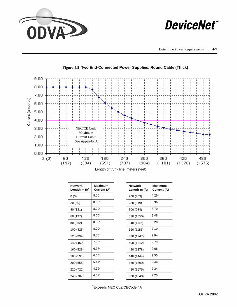
ODVA 2002
Figure 4.5 Two End-Connected Power Supplies, Round Cable (Thick)
Network Length m (ft)
Maximum Current (A)
0 (0) 8.00*
20 (66) 8.00*
40 (131) 8.00*
60 (197) 8.00*
80 (262) 8.00*
100 (328) 8.00*
120 (394) 8.00*
140 (459) 7.68*
160 (525) 6.77*
180 (591) 6.05*
200 (656) 5.47*
220 (722) 4.99*
240 (787) 4.59*
Network Length m (ft)
Maximum Current (A)
260 (853) 4.25*
280 (919) 3.96
300 (984) 3.70
320 (1050) 3.48
340 (1115) 3.28
360 (1181) 3.10
380 (1247) 2.94
400 (1312) 2.79
420 (1378) 2.66
440 (1444) 2.55
460 (1509) 2.44
480 (1575) 2.34
500 (1640) 2.25
NEC/CE Code Maximum
Current Limit See Appendix A
*Exceeds NEC CL2/CECode 4A
Length of trunk line, meters (feet)
Cur
rent
(am
pere
s)
Determine Power Requirements 4-7

ODVA 2002
4-8 Determine Power Requirements
Figure 4.6 Two End-Connected Power Supplies, Flat Cable
NEC/CE Code Maximum
Current LimitSee Appendix A
*Exceeds NEC CL2/CECode 4A
Length of trunk line, meters (feet)
Cur
rent
(am
pere
s)
Network Length m (ft)
Maximum Current (A)
0 (0) 8.00*
20 (66) 8.00*
40 (131) 8.00*
60 (197) 8.00*
80 (262) 8.00*
100 (328) 8.00*
120 (394) 8.00*
140 (459) 7.35*
160 (525) 6.43*
180 (591) 5.72*
200 (656) 5.16*
Network Length m (ft)
Maximum Current (A)
220 (722) 4.69*
240 (787) 4.30*
260 (853) 3.97
280 (919) 3.69
300 (984) 3.44
320 (1050) 3.23
340 (1115) 3.04
360 (1181) 2.87
380 (1247) 2.72
400 (1312) 2.59
420 (1378) 2.46

ODVA 2002
4-9 Determine Power Requirements
Figure 4.7 One Power Supply (End Segment) Round Cable (Mid)
0(0) 25 50 75 100 125 150 175 200 225 250 275 300 (82) (164) (246) (328) (410) (492) (574) (656) (738) (820) (902) (984)
NEC/CE Code Maximum
Current LimitSee Appendix A
Cur
rent
(am
pere
s)
4.50
4.00
3.50
3.00
2.50
2.00
1.50
1.00
0.50
0
Network Length m (ft)
Maximum current (A)
0 (0) 1.50
25 (82) 1.50
50 (164) 1.50
75 (246) 1.50
100 (328) 1.50
125 (410) 1.28
150 (482) 1.08
175 (574) 0.93
200 (656) 0.81
225 (738) 0.72
250 (820) 0.65
275 (902) 0.59
300 (984) 0.55
Length of Trunk Line meters (feet)

ODVA 2002
4-10 Determine Power Requirements
Figure 4.8 One Power Supply (End Segment) Round Cable (Thin)
NEC/CE Code Maximum
Current LimitSee Appendix A
Length of trunk line, meters (feet)
Cur
rent
(am
pere
s)
Network Length m (ft)
Maximum Current (A)
0 (0) 3.00
10 (33) 3.00
20 (66) 3.00
30 (98) 2.06
40 (131) 1.57
50 (164) 1.26
60 (197) 1.06
70 (230) 0.91
80 (262) 0.80
90 (295) 0.71
100 (328) 0.64

ODVA 2002
One Power Supply (End-Connected)
The following example uses the look-up method to determine the configuration for one end-connected power supply. One end-connected power supply provides as much as 8A near the power supply.
1. Determine the total length of the network.
– 106m
2. Add each device’s current together to find the total current.
– 0.10+0.15+0.30+0.10= 0.65A
3. Find the value next largest to the network length using Figure 4.1 on page Page 4-3 to determine the maximum current allowed for the system (approximately).
– 120m (2.47A)
Since the total current does not exceed the maximum allowable current, the system will operate properly (0.65A < 2.47A).
• do the full-calculation method described later in this chapter
• move the power supply to somewhere in the middle of the cable system and reevaluate per the following section
Results
Determine Power Requirements 4-11
powersupply
TR TRP T T T
D1 D2 D3 D40.10A 0.15A 0.30A 0.10A
23m(75 ft)
30m(100 ft)
53m(175 ft)
106m(350 ft)
T
TR = terminating resistor T = T-Port tapPT = Power tap D = device
Important: Make sure that the required power is less than the rating of the power supply. You may need to derate the supply if it is in an enclosure.
Important: If your application doesn’t fit ‘‘under the curve”, you may either:

ODVA 2002
4-12 Determine Power Requirements
One Power Supply (Middle-Connected)
The following example uses the look-up method to determine the configuration for one middle-connected power supply. One middle-connected power supply provides the maximum current capability for a single supply.
1. Add each device’s current together in section 1.
– 1.10+1.25+0.50 = 2.85A
2. Add each device’s current together in section 2.
– 0.25+0.25+0.25 = 0.75A
3. Find the value next largest to each section’s length to determine the maximum current allowed for each section (approximately).
– Section 1 = 140m (2.14A)
– Section 2 = 140m (2.14A)
Section 1 is overloaded because the total current exceeds the maximum current (2.85A>2.14A).
Section 2 is operational since the total current does not exceed the maximum current (0.75A< 2.14A).
Balance the system by moving the power supply toward the overloaded section (section 1). Then recalculate each section.
4A for NEC/CECode compliance.
Results
powersupplysection section
122m(400 ft)
91m(300 ft)
37m(120 ft)
49m(160 ft)
D1
91m(300
122m(400
D2 D3 D4 D5 D6
T T T T T TPT
1.10A 1.25A 0.50A 0.25A 0.25A 0.25A
T T
TR = terminating resistor T = T-Port tapPT = Power tap D = device
Important: Section 1 + Section 2 = 3.6A. This is <
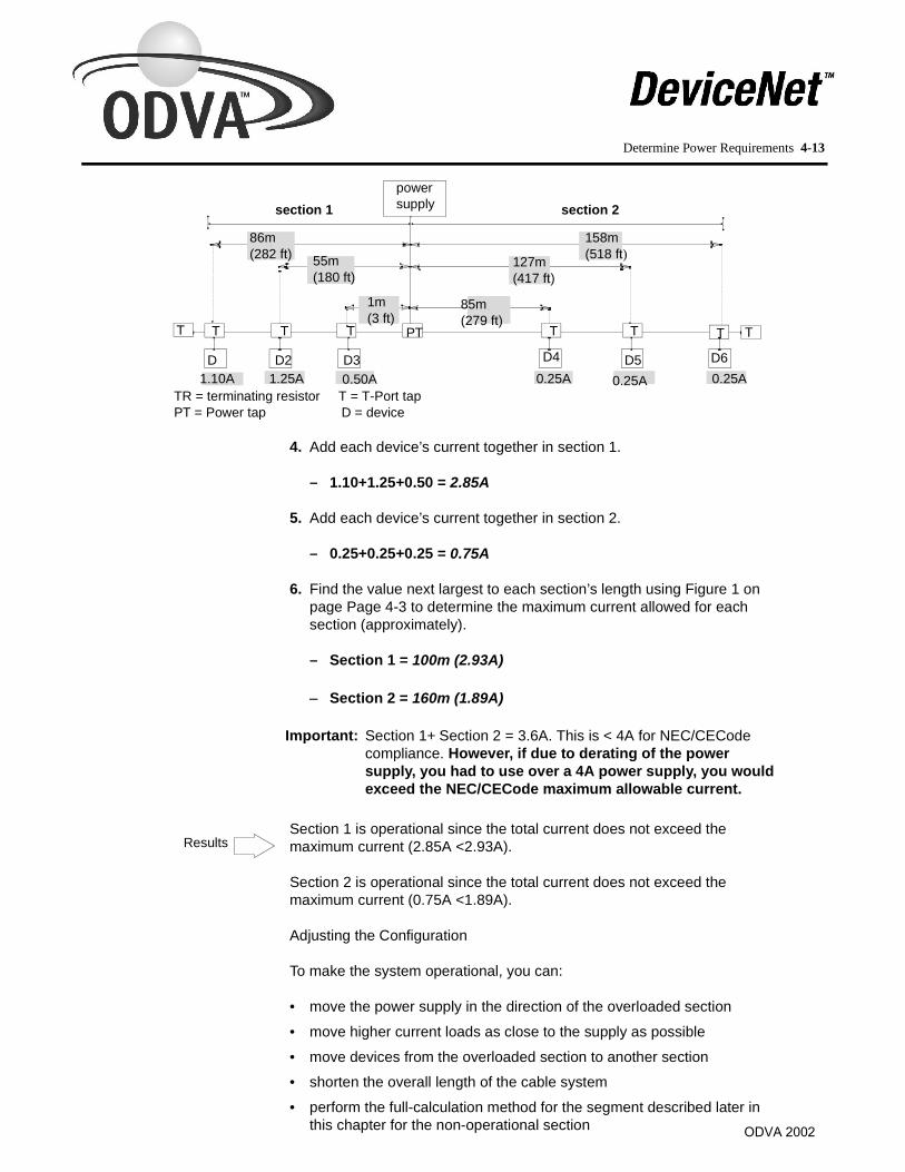
ODVA 2002
Determine Power Requirements 4-13
4. Add each device’s current together in section 1.
– 1.10+1.25+0.50 = 2.85A
5. Add each device’s current together in section 2.
– 0.25+0.25+0.25 = 0.75A
6. Find the value next largest to each section’s length using Figure 1 on page Page 4-3 to determine the maximum current allowed for each section (approximately).
– Section 1 = 100m (2.93A)
– Section 2 = 160m (1.89A)
Section 1 is operational since the total current does not exceed the maximum current (2.85A <2.93A).
Section 2 is operational since the total current does not exceed the maximum current (0.75A <1.89A).
Adjusting the Configuration
To make the system operational, you can:
• move the power supply in the direction of the overloaded section
• move higher current loads as close to the supply as possible
• move devices from the overloaded section to another section• shorten the overall length of the cable system
• perform the full-calculation method for the segment described later in this chapter for the non-operational section
powersupplysection 1 section 2
86m(282 ft) 55m
(180 ft)
1m(3 ft)
85m(279 ft)
127m(417 ft)
158m(518 ft)
T T T T T TPT
D D2 D3 D4 D5 D61.10A 1.25A 0.50A 0.25A 0.25A 0.25A
T T
TR = terminating resistor T = T-Port tapPT = Power tap D = device
Important: Section 1+ Section 2 = 3.6A. This is < 4A for NEC/CECode compliance. However, if due to derating of the power supply, you had to use over a 4A power supply, you would exceed the NEC/CECode maximum allowable current.
Results

ODVA 2002
4-14 Determine Power Requirements
• add a second power supply to the cable system (do this as a last resort) as shown in the following three examples
NEC/CECode Current Boost Configuration
If the national or local codes limit the maximum rating of a power supply, use the following configuration to replace a single, higher current power supply.
This configuration effectively doubles the available current. It has the following characteristics:
• no loads are allowed between the Power taps• fuses between the two Power taps must be removed to segment
the V+ conductor in the trunk line between the taps
– also cut V+ (red) flush with cable jacket
These are the Power tap modifications.
• essentially two independent segments, each of which is a “one power supply end-connected system”
– use Figure 4.5 on page 4-7 for each segment
section 1 section 2powersupply
powersupply91m
(300 ft)152m(500 ft)
T T T T T TPT PT
D3 D2 D1 D4 D5 D61.10A 1.25A 0.50A 0.25A 0.25A 0.85A
protection devicesremoved from centerV+ section(supplies are isolated)V- section is continuous
T T
TR = terminating resistor T = T-Port tapPT = Power tap D = device
removethesefuses
powersupply
powersupply
V+ V- V- V+
CAN_CAN_Ldrain
V+V-
trunk line
ground
Wire Color
Wire identity
Use
white CAN_H signal
blue CAN_L signal
bare drain shield
black V- power
red V+ power

ODVA 2002
Determine Power Requirements 4-15
• each power supply can be rated up to 4A and still meet NEC/CECode Class 2 current restrictions
Two Power Supplies (End-Connected) in Parallel with No V+ Break
The following example uses the look-up method to determine the configuration for two end-connected power supplies. You must use diodes at the power taps to prevent back-feeding of the power supplies. Check your national and local codes for any restrictions on the use of parallel power supplies. The NEC/CECode requires that the power supplies must be listed for parallel operation.
1. Determine the total length of the network.
– 274m
2. Add each device’s current together to find the total current.
– 0.25+0.50+0.10+0.25+1.00+0.10 = 2.20A
3. Find the value next largest to each section’s length using Figure 4.5 on page 4-7 to determine the maximum current allowed for each section (approximately).
– 280m (3.96A)
Since the total current does not exceed the maximum current, the system will operate properly (2.20A <3.96A).
powersupply
powersupply274m
(900 ft)122m(400 ft)
122m(400 ft)
76m(250 ft)
76m(250 ft)
30m(100 ft)
30m(100 ft)
TR TRT T T T T TPT PT
D1 D2 D3 D4 D5 D60.25A 0.50A 0.10A 0.25A 1.00A 0.10A
TR = terminating resistor T = T-Port tapPT = Power tap D = device
Results

ODVA 2002
4-16 Determine Power Requirements
Two Power Supplies (Not End-Connected) in Parallel with No V+ Break
The following example uses the look-up method to determine the configuration for two power supplies that are not end-connected. This configuration provides the most power to the cable system. You must use diodes at the power taps to prevent back-feeding of the power supplies. Check your national and local codes for any restrictions on the use of parallel power supplies.
1. Determine the trunk line length of one end section (for this example we will use section 3).
– 122m
2. Add each device’s current together in section 3.
– 0.25+1.00+0.30 = 1.55A
3. Find the value next largest to the length of section 3 using Figure 4.3 on page 4-5 to determine the maximum current allowed (approximately).
– 140m (3.40A)
Since the total current does not exceed the maximum current, section 3 will operate properly (1.55A < 3.40A).Loading is 46% (1.55/3.40).
powersupply
powersupply
274m(900 ft)
122m(400 ft)
152m(500 ft)
61m(200 ft)
76m(250 ft)
122m(400 ft)
30m(100 ft)
TR TRT T T T T TPT PT
D1 D2 D3 D4 D5 D62.25A 1.50A 2.00A 0.25A 1.00A 0.30A
TR = terminating resistor T = T-Port tapPT = Power tap D = device
segment 2segment 1 segment 3
Important: If the total current in the section exceeds themaximum current, move the power supply closer to theend and repeat steps 1-3 until the total current in the sectionis less than the maximum allowable current.
Results

ODVA 2002
Determine Power Requirements 4-17
Results
Results
4. Determine the trunk line length of the other end section (section 1).
– 76m
5. Add each device’s current together in section 1.
– 2.25A
6. Find the value next largest to the length of section 1 using Figure 4.1 on page 4-3 to determine the maximum current allowed (approximately).
– 80m (3.59A)
Since the total current does not exceed the maximum current, section 1 will operate properly (2.25A <3.59A).Loading is 63% (2.25/3.59).
7. Determine the length of the middle section (section 2).
– 274m
8. Add each device’s current together in section 2.
– 1.50+2.00 = 3.50A
9. Find the value next largest to the length of section 2 using Figure 4.3 on page 4-5 to determine the maximum current allowed (approximately).
– 280m (7.69A)
Since the total current does not exceed the maximum allowable current, section 2 will operate properly (3.50A< 7.69A). Loading is 46% (3.50/7.69).
If the middle section is still overloaded after you move the power supplies closer together, add a third power supply. Then recalculate each segment.
Important: If the total current in the section exceeds themaximum current, move the power supply closer to theend and repeat steps 4-6 until the total current in the sectionis less than the maximum allowable current.
Important: If the total current in the section exceeds the maximum current, move the power supplies closer together and repeat steps 7-9 until the total current in the section is less than the maximum allowable current.
Important: Section 1 + Section 2 + Section 3 = 7.3A. This is >4A and does not comply with the NEC/CECode for Class 2 installations.

ODVA 2002
4-18 Determine Power Requirements
Use the Full-calculation Method
Use the full-calculation method if your initial evaluation indicates that one section is overloaded or if the requirements of your configuration cannot be met by using the look-up method.
Using the Equation A supply that is not end-connected creates two sections of trunk line. Evaluate each section independently.SUM {[(Ln x (Rc)) + (Nt x (0.005))] x In} < 4.65V
Important: To determine spare capacity for future expansion, subtract the actual current from the maximum allowable current. To determine the percentage loading for each segment, divide the maximum allowable current into the actual current.
SegmentMaximum Current - Actual Current =
Spare Capacity % Loading/Segment
1 2.85A - 2.25A= 0.60A 79% (2.25A/2.85A)
2 3.83A - 3.50A= 0.33A 91% (3.50A/3.83A)
3 1.70A - 1.55A= 0.15A 91% (1.55A/1.70A)
Important: Before constructing the cable system, repeat all calculations to avoid errors.

ODVA 2002
Determine Power Requirements 4-19
Term Definition
Ln
L = The distance (m or ft) between the device and the power supply, excluding the drop line distance.n = The number of a device being evaluated, starting with one for the device closest to the power supply and increasing by one for the next device. The equation sums the calculated drop for each device and compares it to 4.65V.
Rc
Thick cableMetric 0.015 Ohms/mEnglish 0.0045 Ohms/ft
Mid cableMetric 0.023 Ohms/mEnglish 0.0069 Ohms/ft
Thin cableMetric 0.069 Ohms/mEnglish 0.021 Ohms/ft
Flat Cable Metric 0.019 Ohms/m English 0.0058 Ohms/ft
Nt
The number of taps between the device being evaluated and the power supply. For example:• when a device is the first one closest to the power supply, this number is 1• when a device has one device between it and the power supply, this number is 2• when 10 devices exist between the evaluated device and the power supply, this number is 11.For devices attached to a multi port tap, treat the tap as one tap. The currents for all devices attached to one of these taps should be summed and used with the equation only once.For flat cable, Nt = 1 + twice the number of intermediate splice kits.
(0.005) The nominal-contact resistance used for every connection to the trunk line.
In
I = The current drawn from the cable system by the device.For currents within 90% of the maximum, use the nominal device current. Otherwise, use the maximum rated current of the device. For DeviceBox taps or DevicePort taps, sum the currents of all the attached devices, and count the tap as one tap.n = The number of a device being evaluated, starting with one for the device closest to the power supply and increasing by one for the next device.
4.65V The maximum voltage drop allowed on the DeviceNet trunk line. This is the total cable system voltage drop of 5.00V minus 0.35V reserved for drop line voltage drop.

ODVA 2002
One Power Supply (End-Connected)Example of Thick Cable
The following example uses the full-calculation method to determine the configuration for one end-connected power supply on a thick cable trunk line.
• Device 1 and Device 2 cause the same voltage drop but Device 2 is twice as far from the power supply and draws half as much current.
• Device 4 draws the least amount of current but it is furthest from the power supply and causes the greatest incremental voltage drop.
1. Find the voltages for each device using the equation for thick cable.
SUM {[(Ln x (0.0045)) + (Nt x (0.005))] x In} < 4.65V.
A.[(50 x (0.0045)) + (1 x (0.005))] x 1.00 = 0.23V
B.[(100 x (0.0045)) + (2 x (0.005))] x 0.50 = 0.23V
C.[(400 x (0.0045)) + (3 x (0.005))] x 0.50 = 0.91V
D.[(800 x (0.0045)) + (4 x (0.005))] x 0.25 = 0.91V
1. Add each device’s voltage together to find the total voltage.
0.23V + 0.23V + 0.91V + 0.91V = 2.28V
Since the total voltage does not exceed 4.65V, the system will operate properly (2.28V <4.65V).
The percent loading is found by dividing the total voltage by 4.65V.
%Loading = 2.28/4.65 = 49%
powersupply
244m(800 ft)
122m(400 ft)
30m(100 ft)15m
(50 ft)TR TRPT T T T T
D1 D2 D3 D41.0A 0.50 0.50 0.25
TR = terminating resistor T = T-Port tapPT = Power tap D = device
powersupply
244m(800 ft)
122m(400 ft)
30m(100 ft)15m
(50 ft)TR TRPT T T T T
D1 D2 D3 D41.0A 0.50 0.50 0.25
TR = terminating resistor T = T-Port tapPT = Power tap D = device
Results
D1
D2
D3
D4
1.0A
0.50A
0.50A
0.25A
4-20 Determine Power Requirements

ODVA 2002
Determine Power Requirements 4-21
One Power Supply (Middle-Connected)
Example of Thick Cable
This example is used to check loading on both sides of a middle-connected supply on a thick cable trunk line. Keep the loads, especially the higher ones, close to the power supply. If the device location is fixed, put the power supply in the center of the highest current concentration.
According to the look-up method, section 1 is operational while section 2 is overloaded.
1. Find the voltages for each device in section 1 using the equation for thick cable.
SUM {[(Ln x (0.0045)) + (Nt x (0.005))] x In} < 4.65V.
A.[(100 x (0.0045)) + (1 x (0.005))] x 0.25 = 0.12V
B.[(400 x (0.0045)) + (2 x (0.005))] x 0.25 = 0.45V
C.[(800 x (0.0045)) + (3 x (0.005))] x 0.25 = 0.90V
2. Add each device’s voltage together to find the total voltage for section 1.
0.12V + 0.45V + 0.90V = 1.47V
T T T T T
D3 D2 D1 D4 D5 D6
0.25A 0.25A 0.25A 0.25A 1.5A 0.5A
TR = terminating resistor T = T-Port tapPT = Power tap D = device
Value of Section 1 Section 2Total maximum current
1.25A (approximately)
1.25A (approximately)
Total current required 0.75A 2.25A
D10.25AD2
D30.25A

ODVA 2002
4- 22 Determine Power Requirements
3. Find the voltages for each device in section 2 using the equation for thick cable.
SUM {[(Ln x (0.0045)) + (Nt x (0.005))] x In} < 4.65V.
A.[(200 x (0.0045)) + (1 x (0.005))] x 0.25 = 0.23V
B.[(400 x (0.0045)) + (2 x (0.005))] x 1.5 = 2.72V
C.[(800 x (0.0045)) + (3 x (0.005))] x 0.5 = 1.81V
4. Add each device’s voltage together to find the total voltage for section 2.
0.23 + 2.72 + 1.81 = 4.76V
Since the total voltage in section 2 exceeds 4.65V, the system will not operate properly (4.76V > 4.65V).
Attempt to correct this overload by moving the power supply 91m (300ft) toward the overloaded section. Now there are four devices in section 1 and two devices in section 2. Once you’ve moved the power supply, try the calculations again.
1. Find the voltages for each device in section 1 using the equation for thick cable.
SUM {[(Ln x (0.0045)) + (Nt x (0.005))] x In} < 4.65V.
A.[(100 x (0.0045)) + (1 x (0.005))] x 0.25 = 0.11V
B.[(400 x (0.0045)) + (2 x (0.005))] x 0.25 = 0.45V
C.[(700 x (0.0045)) + (3 x (0.005))] x 0.25 = 0.79V
D.[(1100 x (0.0045)) + (4 x (0.005))] x 0.25 = 1.24V
Results
T T T T T TPT
D3 D2 D1 D5 D6
0.25A 0.25A 0.25A 1.5A
TR TR
TR = terminating resistor T = T-Port tapPT = Power tap D = device
section 1 section 2335m(1100 ft) 213m
(700ft) 122m(400 ft)
30m(100 ft)
30m(100 ft)
152m(580 ft)
0.5AD4
0.25A
0.25AD2
0.25A
D10.25A
D3
D40.25A
D1
D2
D3
0.25A
1.5 A
0.5A
powersupply

ODVA 2002
Determine Power Requirements 4- 23
2. Add each device’s voltage together to find the total voltage for section 1.
0.11 + 0.45 + 0.79 + 1.24= 2.59V
3. Find the voltages for each device in section 2 using the equation for thick cable.
SUM {[(Ln x (0.0045)) + (Nt x (0.005))] x In} < 4.65V.
A.[(100 x (0.0045)) + (1 x (0.005))] x 1.5 = 0.68V
B.[(500 x (0.0045)) + (2 x (0.005))] x 0.5 = 1.13V
4. Add each device’s voltage together to find the total voltage for section 2.
0.68 + 1.13 = 1.81V
Since the total voltage does not exceed 4.65V in either section, the system will operate properly - section 1 (2.59V < 4.65V)section 2 (1.81V < 4.65V).
The percent loading is found by dividing the total voltage by 4.65V.
Section 1% Loading = 2.59/4.65 = 56%Section 2% Loading = 1.81/4.65 = 39%
D51.5A
D60.5A
Results

ODVA 2002
4-24 Determine Power Requirements

Commissioning, Troubleshooting and Diagnostics
Network Measurement Tools
There are several different type of diagnostic and troubleshooting tools available to aid you in the initial commissioning of the network, further troubleshooting during operation and as an ongoing means of monitoring its health. For a complete listing of the most recent diagnostic/troubleshooting tools available see www.odva/products/diagnostics . The broadest category of tools are those which are general purpose such as a voltmeter, oscilliscope, time domain reflectometer, etc. These analytical tools can confirm connections, verify cable lengths and the proper installation of terminations as well as being able to measure voltages and confirm signal levels. This category of tools requires a user with advanced knowledge of both the measuring tool and the DeviceNet specification.
The second category of tools are protocol-specific and include a variety of both passive and active hand-held meters. Passive instruments are designed to locate short circuits, opens, confirm terminations and cable lengths. Active handheld devices are designed to give "dial in" measurements of the physical layer voltages such as common mode voltage as well as data packet characteristics such as node error count or rate and bandwidth utilization. These protocol-aware measuring tools are more user friendly in that they typically use plug-play network connections.
Lastly there are a variety of software tools available to monitor network traffic which can aid in commissioning and diagnostics. For instance some configuration tools can monitor traffic and errors produced in the network. More sophisticated software tools such as protocol analyzers parse out and decode both CAN and DeviceNet messages to get into refined issues such as device communications and timing. These tools require a higher level of sophistication and are not designed specifically to address physical layer issues.
Verifying Network Installation
VERIFYING NETWORK INSTALLATION - Commissioning the Network
Prior to making any measurements use the quick check list below to verify that the physical media system has been installed and designed properly:
• Total device network current draw does not exceed power supply current limit
Chapter 5
ODVA 2002

ODVA 2002
5-2 Commissioning, Troubleshooting and Diagnostics
• Number of DeviceNetTM nodes does not exceed 64 on one network. The
practical limit of DeviceNetTM nodes may be 61 devices since you should allow one node each for the scanner, the computer interface module, and an open node at node 63.
• No drop should be greater than 6m in length (20 ft)
• Cumulative drop line budget does not exceed the maximum allowable per the network baud rate limit
• Total network trunk length does not exceed the maximum allowable per the network data rate and cable type
• Terminating resistors are on each end of the trunk line
• Ground V-, drain and (for round media) shield at only one location preferably in the center of the network
• Check the physical media prior to applying power
– All connections are inspected for loose wires or coupling nuts
– Check for opens or shorts
– Check the proper value of the terminating resistors
Confirming Media CONFIRMING MEDIA TOPOLOGY AND CONNECTIONS
The following measuring procedures are suggested PRIOR to commissioning your network:
1. Use a Time Domain Reflectometer, DVM or handheld network media checker to verify cable lengths, cable types, termination and connection integrity. These tests are to be conducted PRIOR to connection of devices and power on the network.
2. Insure that both termination resistors are connected to the network. Measure and record DC resistance between CAN_H and CAN_L at the middle and the ends of the network.

Commissioning, Troubleshooting and Diagnostics 5-3
ODVA 2002
3. Temporarily disconnect from ground and measure between ground and measure between ground and the disconnected grounding point.
Record all of the above in the attached "Baseline and Test Report"
4.Measure the network’s electrical characteristics with the following as the recommended minimum to make and record:
A. Bus Power
B. Shield Voltage
C. Common Mode Voltage
Record all of the above in the attached "Baseline and Test Report"
5.After scanner(s) and any other connection originators have been configured and are operating normally, measure network protocol characteristics with the following the recommended minimum to make and record:
A. Network Error Rate
B. Error Counter
C. % Network Bandwidth
D. Network Message Rate/Sec
Record all of the above in the attached "Baseline and Test Report"
Measured Value Action<50 Ohms Check for short circuit between
CAN_H and CAN_L wiringCheck for more than two
terminating resistorsCheck nodes for taulty trnasceivers
50-70 Ohms Normal
71-125 Ohms Check for open circuits in CAN_H and CAN_L wiring
Check for only one terminating resistor
>125 Ohms Add termination resistors
Measured Value Action<1 Megaohm Check for additional grounded V- or
shield wires>1 Megaohm Normal

ODVA 2002
5-4 Commissioning, Troubleshooting and Diagnostics
Proper Network Maintenance
PROPER NETWORK MAINTENANCE
Once the network has been installed and has been successfully commissioned and baseline measurements recorded, periodic measurements can improve network availibility. The most obvious place to begin this checkup is by comparing the network’s operating characteristics against the established baseline. Checkup frequency and thoroughness is the key to early detection of deteriorating network properties. A continuous monitoring of these baselined parameters is ideal, however, a quick protocol-aware checkup every few weeks would be adequate to detect any deteriorations of network performance.
ANALYZING SYMPTOMS
Use the following to analyze the most common symptoms and their likely sources.
Most devices have LEDs, some have alphanumeeric or other displays. If any of these show error codes or messages, read the manufacturer’s data sheets to intrepret the codes.
SYMPTOMS:
1. Nodes at the end of the trunk stop communicating after operating normally
2. The network communicates only when the number of nodes is decreased or the trunk length is reduced
3. Properly configured slaves are not detected by the scanner
CHECKS:
– Check the communications at the end of the network.
– Check the common mode voltage.
SUGGESTED ACTIONS:
– Move nodes from overloaded section to less overloaded section
– Shorten the overall length of the network cable
– Move power supply in direction of the overloaded section of the network
– Move high current nodes (e.g. valve banks) close to the power supply
– Add second power supply
– Break network into two (2) separate networks
Common Mode Problems

ODVA 2002
Commissioning, Troubleshooting and Diagnostics 5-5
Bus Errors Bus Errors
SYMPTOMS:
1. Nodes intermittant-they drop off suddenly and unexpectantly
2. LEDs or other displays indicate “buss off” errors.
CHECKS:
– Use protocol-aware tool to measure bus error rate.
SUGGESTED ACTIONS:
– Node baud rate set incorrectly affects other nodes when it attempts to go online
– Replace suspected faulty device and re-check error rates
– Intermittent cables - check by shaking/bending/twisting the suspected cable or connection while looking at the error rates
Bus Traffic Problems Bus Traffic Problems
SYMPTOMS:
1.Nodes stop communicating and devices time out. No communication from a device
CHECKS:
– Check bandwidth using protocol-aware device
SUGGESTED ACTION:
– Check scanner configuration as scan rate may be set incorrectly
– Inter-scan delay/scan interval too short can cause device timeouts
– Inter-scan delay/scan interval too long can reduce system performance and makes inefficient use of available bandwidth
– Check Change-of-State devices consuming excessive bandwidth -increase production inhibit time or change these devices to poll, strobe or cyclic communications.
– Look for nodes with excessive bandwidth or much higher than average MAX value
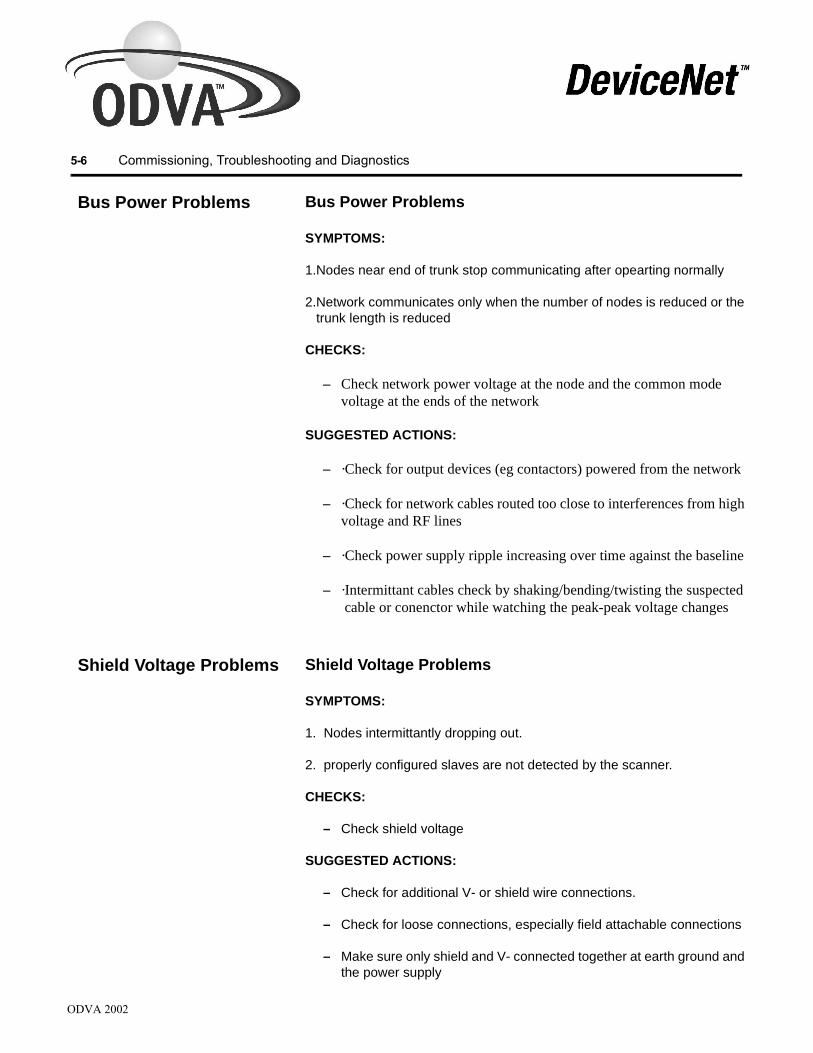
ODVA 2002
5-6 Commissioning, Troubleshooting and Diagnostics
Bus Power Problems Bus Power Problems
SYMPTOMS:
1.Nodes near end of trunk stop communicating after opearting normally
2.Network communicates only when the number of nodes is reduced or the trunk length is reduced
CHECKS:
– Check network power voltage at the node and the common mode voltage at the ends of the network
SUGGESTED ACTIONS:
– ·Check for output devices (eg contactors) powered from the network
– ·Check for network cables routed too close to interferences from high voltage and RF lines
– ·Check power supply ripple increasing over time against the baseline
– ·Intermittant cables check by shaking/bending/twisting the suspected cable or conenctor while watching the peak-peak voltage changes
Shield Voltage Problems Shield Voltage Problems
SYMPTOMS:
1. Nodes intermittantly dropping out.
2. properly configured slaves are not detected by the scanner.
CHECKS:
– Check shield voltage
SUGGESTED ACTIONS:
– Check for additional V- or shield wire connections.
– Check for loose connections, especially field attachable connections
– Make sure only shield and V- connected together at earth ground and the power supply

ODVA 2002
Commissioning, Troubleshooting and Diagnostics 5-7
Common Faults Common FaultsIf you are having difficulty with the network make sure to check the following most common network problems :
– More or less than two (2) terminators
– Relaxed connector pin - especially those which use a soft brass contact on the female socket. The DeviceNetTM specification requires that connectors are good for at least 1000 insertions. Phosphor-Bronze contacts are more likely to meet this requirement.
– Excessive drop line cable length
– Too many drop cables - cumulative drop length
– Excessive trunk line length - especially with THIN cable
– Improper shield and ground connection at the power supply
– Shorts and opens in manually-wired connectors
– Failure to perform power distribution calculations for new installations and again when adding nodes i.e your power budget has been exceeded
– Using a typical device current rather than maximum current for power distribution calculations
– Scan interval configured faster than the network can handle
Flat Cable Shorts Flat Cable Shorts
Badly installed flat cable taps can cause short sircuits. These can be difficult to find because the taps are not designed to allow removal. A time domain reflectometer or handheld network media checker can indicate the approximate distance to a short. This may not be accurate enough if there are several taps within a short distance of each other. The following technique can be used to identify the shorted tap more precisely.
Disconnect all devices by removing all of the snap-on connection interfaces. Use two open-style connection interfaces for the test. Use one of these to inject about 100mA DC into the shorted pair of conductors. Use the other with a multimeter to measure mV across the shorted pair. Move the measurement point to different taps - the voltage should decrease as it gets nearer to the short. If you see no change, the short is probably on the other side of the current injection point. If you see no change on either side, the short is probably at the current injection point. Move the current injection point to another tap and repeat the test. The lowest voltage measured should be at the shorted tap.

ODVA 2002
5-8 Commissioning, Troubleshooting and Diagnostics
The 100mA current can be generated by a low-voltage DC power supply and a resistor. Be careful if using the 24V DC network supply for this - the resistor (240 Ohms) would dissipate 2.4 watts and would get hot. It should have at least a 5 watt rating. It is better to use a 1.5V cell and a 15 Ohm resistor, which will only dissipate about 0.15 watts.
Once the shorted tap is identified, the flat cable must be cut on either side and the faulty tap removed. Use a splice kit to repair the cable. The splice kit consists of two taps with end caps for sealing, and two connection interfaces permanently joined by a short length of cable.
Never attempt to re-use a flat cable tap.

Wha
Appendix A
Understanding Select NEC Topics
t’ s in this Ap pendix Be aware that the following topics from the National Electrical Code (NEC) 725 (revision 2002) impact the configuration and installation of DeviceNet systems in the United States. There also may be additional NEC sections and local codes that you must meet. Other codes exist outside of the United States that may also affect your installation.
Class 1 (CL1) Cable
Per NEC specifications for a Class 1 circuit (see NEC Article 725), the energy in the circuit anywhere is limited to 1000 VA. A Class 1 circuit requires that the cables used must have jacketing with 600V isolation and pass the CL1 burn test.
DeviceNetTM specifies the power source to be a regulated maximum of 24V dc and the power circuit is limited to 8A. Applying this to a Class 1 circuit running at 24V dc, a DeviceNetTM certified cable with a 600V jacket isolation rating meets all requirements to be used in a Class 1 circuit. So, based on DeviceNetTM specification, the cable’s power carrying conductors are sized for an 8A maximum load.
Class 2 (CL2) Cable
Per NEC specifications for a Class 2 circuit (see NEC Article 725), the energy in the circuit anywhere is limited to 100 VA and the cable’s jacketing used must have a 300V minimum isolation rating. Based on a 30V dc system your circuit would be limited to 3.3A.
DeviceNetTM specifies the power source to be a maximum of 24V dc. Applying this to a Class 2 circuit running at 24V dc, the maximum allowable current is 4A. A DeviceNetTM certified cable with a 300V jacket isolation rating meets all requirements to be used in a Class 2 circuit. So, based on the DeviceNetTM specification, the cable’s power carrying conductors, are sized for a 8A maximum load.
ODVA 2002

ODVA 2002
A-2 Understanding Select NEC Topics
Suppliers of DeviceNetTM physical components use the above information to provide components you can use to cable DeviceNetTM systems
The DeviceNetTM specifications provide for both “open and closed style” wiring terminations. You can engineer a wiring system for a DeviceNetTM installation that lays out a trunk line in accordance with the requirements of the Class 1 guidelines and uses drop lines in accordance with Class 2 guidelines. Care must be taken at the point where the two guidelines meet. At that point you must put in place a way to limit the energy on each wire to be in accordance with the NEC guidelines. In short, the energy in the drop line must be limited to no more that 100 VA. How you accomplish that is your decision. Most people resolve this issue by isolating the trunk from the drop line with different power sources. Other ways to limit energy may give you the same protection.
Specifying Article 725 Topics
Round (Thick, Mid & Thin) and Class 2 Flat Media
• power limitations of Class 2 circuits
– The power source for Class 2 circuits must be either inherently limited, thus requiring no overcurrent protection, or limited by a combination of a power source and overcurrent protection.
• marking
– Class 2 power supplies must be durably marked where plainly visible to indicate the class of the supply and its electrical ratings.
• interconnection of power supplies
– Class 2 power supplies must not be paralleled or otherwise interconnected unless listed for such applications.
Class 1 Round or Flat Media
• power limitations of Class 1 circuits
– The overcurrent protection shall not exceed 10 amperes per NEC article 725-23.
– Consult the product manufacturer to determine if the device is suitable for installation with a Class 1 power source.
Appendix B
Powering Output Devices
Wide Available Voltage Range
You can power some output devices on the DeviceNetTM network. The application must allow the voltage to remain within the DeviceNetTM specification limits of 11-25V dc. Most actuators need to be powered by a separate power supply. They usually require more power than is practically available from DeviceNetTM. Also, the large voltage variation of 11-25V that DeviceNetTM allows is typically beyond the range that most available actuators or output devices can safely operate over.
You can use DeviceNetTM power to operate output devices such as hydraulic and pneumatic solenoid valves, pilot and stack lights, and motor starter coils with the following caution:
The DeviceNetTM common mode drop voltage specification limit of 10 volts, 5 volts in each power supply V+ and V- conductor, will never be a concern. This is because in the design process we start with a 24V dc power supply and allow for the 4% stack-up tolerance which leaves 23V dc to work with. From here we consider the output device’s minimum required operating voltage of 19.2 volts. This gives 23V dc-19.2V dc = 3.8V dc for the common mode voltage or 1.9V dc in each conductor. This is far more restrictive than the 5 volts of the DeviceNetTM specification and will result in shorter allowable distances for the installation.
!ATTENTION: Do not let DeviceNetTM voltage at the relevant node exceed the output device’s acceptable voltage range. Output devices rated 24V dc rarely are specified to operate below 19.2V dc or -20% of their 24V dc rating. Many only operate down to 20.4V dc or -15% of the rated voltage. This means that the DeviceNetTM network design must not allow the available voltage to drop below 19.2 volts, for example, instead of the 11 volts that the DeviceNetTM specification allows. This higher lower voltage limit which is within the DeviceNetTM specification will actually restrict the distance of the DeviceNetTM network from what would be possible if actuators were not utilizing the DeviceNetTM power
Important: Design your network to make sure that sufficient voltage is available to operate the output device wherever it is installed. This is especially important when it is connected at the farthest location from the power supply.
ODVA 2002

ODVA 2002
B-2 Powering Output Devices
Noise or Transient Protec tion
The typical actuators used in DeviceNetTM control systems utilize inductive coils that generate transients when de-energized. You must use appropriate protection to suppress transients during coil de-energization. Add a diode across the inductive coil to suppress transients on the actuator’s dc coils. Use a MOV varistor module suppressor for a 24V dc coil if the added drop out time with the diode is unacceptable. This varistor module must clamp the transient voltage across the coil at 55 volts to prevent the output contact from arcing on switch separation. Read the output device’s specificaitons. It may have more restrictive transient suppression requirements than stated herein (lower maximum voltage).
Typical actuators used in DeviceNetTM control systems use inductive coils and limit current transients on energization by their inherent L/R time constant. Any transients due to contact bounce on energization will be suppressed by the transient protection utilized for coil de-energization.
!ATTENTION: Do not use DeviceNetTM power to actuate dc coils that use economizing coils to operate. These coils have high inrush currents.

DeviceNet Baseline & Test Report Tested By: Company
Phone e-mail
Measurement Date Measurement Time Network Identification
Network Location (Company name & Address)
Network Characteristics Single Master # ___ Multi Master # ___, ___, ___, ___ Single power supply Multiple power supplies (No. ___) 125 Kbaud 250 Kbaud 500 Kbaud Network uses Thick media Network uses Thin media Network uses Mid media Network uses Flat media Media Testing Trunk checked for short circuit Trunk checked for opens Wiring of trunk checked Drops checked for short circuit Drops checked for opens Check termination values Shield and V- connected to ground at single point on network-at power supply
Node List (According to network administrator, or “Network Who” scan) 0 1 2 3 4 5 6 7 8 9 10 11 12 13 14 15 16 17 18 19 20 21 22 23 24 25 26 27 28 29 30 31 32 33 34 35 36 37 38 39 40 41 42 43 44 45 46 47 48 49 50 51 52 53 54 55 56 57 58 59 60 61 62 63
Basic Observations & Symptoms Reported Symptoms
No problems reported Intermittent problems (___ min, ___ hrs, ___ days) Constant problems
All nodes affected Some nodes affected
Error codes: Error codes per node
Node Network Status LEDs (LED indications refer to Network Status or Combined Module/Network Status LEDs)
All nodes active (green) Some nodes active (green) Some nodes inactive (blink green)
Some nodes faulted (red) All nodes occasionally inactive (green/ blink green) Some nodes occasionally inactive (green/ blink green)
All nodes with no power (LED off) Some nodes with no power (LED off)
Appendix C

Physical Layer Measurements ( NetMeter TM DeviceNet Detective Multimeter Oscilloscope Connected to network in proximity to node # ___). Use NetMeter to take all of the following measurements (NetMeter switch positions are shown beside each measurement). You can also collect a limited number of measurements using other tools such as the DeviceNet Detective , multimeter and/or oscilloscope (indicated by icons in the table). Note: This document shows some measurements that are only practical with specific proprietary test instruments. All measurements are theoretically possible with general-purpose instrumentation such as oscilloscopes, but some would be very tedious. Proprietary instruments make it easy to perform the tests for which they are designed. This page indicates instruments that are believed to have such capabilities, but you should NOT assume that it is complete or accurate. Consult the instrument manufacturers for more information about each instrument’s capabilities.
Autosearch Results (record measurements as indicated by NetMeter Autosearch function and check for and/or with each reported problem)
No faults found ☺ NetMeter gathered data for (H:M:S) ___:___:___ before
Measurement Min Max Measurement Min Max [2] Bus error rate (/S) [3] Bus traffic, bandwidth
(%)
[4] Bus power, DC (V) [4] Bus power, P-P (V) [5] Shield Voltage (V) [6] Common Mode Voltage [7] CANH/L Recessive Diff. (V)
[8] CANH/L Dominant Diff. (V)
[9] CANH Recessive (V) [10] CANH Dominant (V) [11] CANL Recessive (V) [12] CANL Dominant (V)
Overall Subnet Measurements (only important for baseline performance, or for more detail if NetMeter Autosearch indicates problems)
Measurement “Live” Min Max Measurement “Live” Min Max [2] Bus error rate (/S) [2] Bus error count [3] Bus traffic, bandwidth (%) [3] Bus traffic, message rate (/S) [4] Bus power, DC (V) [4] Bus power, P-P (V) [5] Shield Voltage (V) [6] Total Common Mode Voltage [7] CANH/L Recessive Diff. (V) [8] CANH/L Dominant Diff. (V) [9] CANH Recessive (V) [10] CANH Dominant (V) [11] CANL Recessive (V) [12] CANL Dominant (V)
Measurement Network idle Network active (normal operation) CAN_H average (V) CAN_L average (V)
“Network idle” means all scanners and other connection originators inactive, disabled or disconnected. In this state the average voltages should be the same, about 2.5 – 3.5 volts. This will vary with position on the network. Repeated measurements should be taken at the same point for valid comparisons. With network active you are using a DC meter to measure a complex high frequency waveform, so these measurements are only approximate. Different meters may give different results. Repeated measurements should be taken with the same instrument at the same point for valid comparisons. CAN_H average should be about 0.5 – 1 volt higher than when idle. CAN_L average should be about the same amount lower than when idle. Because multimeters are not intended for this sort of waveform it is possible that they might cause errors on an active network. Experience suggests that this is rare with modern, high-impedance instruments, but if you experience this problem or are concerned about the possibility, construct a pair of probes with 100 kOhm resistors and heat-shrink sleeving. This is much higher than the network impedance (so it can’t significantly affect the network) and much lower than the meter impedance (so it does not introduce a significant error).
C-2 DeviceNet Baseline & Test Report

Per-node Measurements (only important for baseline performance or for more detail if subnet measurements indicate problems). [2] Bus error rate (/S) [3] Bus traffic, bandwidth utilization (%) [3] Bus traffic, message rate (/S) Node
Number “Live” Min Max [2] Bus error count
“Live” Min Max “Live” Min Max
DeviceNet Baseline & Test Report C-2


Numerics C (Con't)10-pin linear plug 1-6 connecting5-pin linear plug 1-6 drop lines 3-5
A power supplies 3-11adequate power to a Multi port tap preterminated thin cable
worst case scenario 4-1 stripped conductors to micro female 2-12adjusting the configuration 4-13 stripped conductors to mini female 2-12
auxiliary power cable to a T-Port tap from open device preterminated thin cablediagram 3-11 mini male to conductors 2-12installation 3-11 to a T-Port tap from sealed device preterminated thin cableC mini male to micro female 2-11
cable installation mini male to mini female 2-11Flat cable 3-6 to the trunk line via direct connection 2-5
cable position to the trunk line using connectorsFlat cable 3-8 open-style 3-2
cable preparation 3-1 sealed-style 3-3cables to flat cable micro T-Port tap 2-10
maximum distance 1-3 connectorsdetermining 1-3 Flat cable
preterminated IDC’s 2-10thick 2-11 installation 3-6thin 2-11 open-style
CECode attaching to trunk line 3-2current boost configuration fixed 3-5
example 4-14 pinouts 3-11circuit sealed-style
Class 2 attaching to trunk line 3-2limitations A-2 micro-style 1-6, 3-3power source A-2 mini-style 1-6, 3-3
class 1 conventions used in manual P-2Flat cable current
total allowable current 1-10 boost example 4-14class 1 applications cable system
Flat cable rating A-1 maximum 4-18class 1 cable maximum allowable
maximum load A-1 one power supply (end connected) example 4-11NEC specifications A-1 one power supply (middle connected) example 4-12
class 2 segment between two power supplies figure 4-10total allowable current A-1 two power supply (end connected) example 4-15
class 2 cable two power supply (not end connected) example 4-15maximum load A-1 maximum drop line 1-10NEC specifications A-1 equation 1-10
common mode drop voltage name plate setting 1-12DeviceNet B-1 thick cable 1-10
communication rate 1-3 thin cable 1-10determining 1-4 current chart
components end segmentflat media network diagram 2-1 two power supplies round cable thick 4-7
components diagram 2-1 one power supply conductors end segment
V- 1-11 flat cable 4-4V+ 1-11, 4-14 round cable mid 4-9
configuration round cable thin 4-10adjusting 4-13 two power suppliesNEC/CECode current boost 4-14 end segment flat cable 4-8one power supply end connected look-up method 4-11 flat cable 4-6middle connected 4-12 round cable thick 4-5
Index

D D (Con't)definition drift
open-style connector temperature 1-9fixed 1-5 time 1-9plug-in 1-6 drop cable
sealed connector flat cable installationmicro-style 1-6 open-style 3-9mini-style 1-6 drop line
terminating resistor 1-7 allowable current 1-10definitions connection types
flat cable 1-2 open-stylepower supply formulas 4-18 hard-wire screw terminals 3-5thick cable 1-2 pluggable screw connectors 3-5thin cable 1-2 soldered 3-5
determining adequate power sealed-stylepower usage 4-3 quick disconnect connectors
DeviceNet common mode drop cumulative length 1-4voltage B-1 definition 1-4
DeviceNet power determining communication rate 1-4economizing coils B-2 current 1-10high inrush currents B-2 equation 1-10
DeviceNet including as part of cable length 1-4powering output devices 4-1 rating 1-10
DeviceNet voltage limits Eoutput power B-1 economizing coils
diagram DeviceNet power B-2auxiliary power cable 3-11 end cap installation 3-10end cap installation end segment current chart
flat cable 3-12 two power suppliesflat cable 3-6 round cable (thick) 4-7flat cable connector installation 3-6 endcapflat cable connectors 2-10 flat cable
diagrams terminating resistor 1-8components 2-1 equationmulti port tap 2-7 current 1-10direct connection 2-9 equation 1-10Power tap 2-5, 2-7,3-11 including as part of cable length 1-4preterminated rating 1-10
thick cable 2-11 examplesthin cable 2-11 NEC/CECode current boost configuration 4-14
connecting to T-Port tap 2-11 power supplythick cable 2-2 onemid cable 2-3 end connected 4-11, 4-20thin cable 2-3 end segment 4-10T-Port tap 2-5 middle connected 4-12, 4-20
diodes twotransient protection B-2 end connected 4-15
direct connection not end connected 4-16connecting to trunk line 2-4 Fdescription 1-5, 2-9 figuresdiagram 1-5, 2-9 power supplyopen-style 2-5, 2-9 two segment between 4-10zero-length drop 1-5 fixed
distance connector open-style 1-5maximum cable 1-4
determining 1-4
Index

F (Con't) Lflat cable line regulation 1-9
class 1 linear plug total allowable current 1-9 10-pin 1-6definition 1-2 5-pin 1-6size 1-2 load regulation 1-9total allowable current loading
class 2 1-9 percentages 4-23use of connectors look-up method
flat cable 2-11 configurationwire contents 1-3 one power supply end connected 4-12
flat media examplesnetwork diagram 2-1 NEC/CECode current boost
full-calculation method configuration 4-14description 4-18 power supplyequations 4-18 oneexamples end connected 4-11
power supplies - one middle connected 4-12end connected 4-19 twomiddle connected 4-20 end connected 4-15
full-calculation method 4-18 not end connected 4-16G figures
grounding 1-16, 4-14 power supplyguidelines one
supplying power 1-9 middle segment 4-12H making system operational 4-13
hard wire taps Minstalling maximum current multi port tap 3-4 % loading/segments
Power tap 3-4 table 4-18high inrush currents network length
DeviceNet power B-2 one power supplyhydraulic solenoid valves flat cable 4-5
output power B-1 round cableI thin 4-10
IDC’s two power supplies 4-6flat cable connectors 2-10 end segment
installation flat cable 4-9auxiliary power cable 3-11 flat cable 4-7flat cable maximum load
end cap 3-11 class 1 cable A-1flat cable connector 3-6 class 2 cable A-1flat cable open-style minimum name-plate current rating single power supply 1-9
drop cable 3-9 minimum required operating voltage output devices B-1open-style connectors 3-2 motor starter coils output power B-1pluggable screw-connector 3-2 N
installing NECmulti port tap 3-5 about P-2 hard wire taps Class 2 A-1
multi port tap 3-4 current boost configurationPower tap 3-4 example 4-14
power supplies 3-11 section 725 A-1Power taps 3-4 NEC regulations power conductors A-1K
keying informationT-Port tap 2-6
Index

N PNEC specifications parallel application
class 1 cable A-1 power supplies 1-9class 2 cable A-1 plu 10-pin 1-6
NEC/CECode current boost installation 3-2configuration 4-14 plug-in
NEMA rating connectorflat cable terminating resistor open-style 1-5
sealed 1-7 pneumatic valvesunsealed 1-7 output power B-1
network length powermaximum current determining
end segment using look-up method 1-12, 4-3two power supplies round cable (thick) 4-7 limitations A-1
one power supply flat cable end segment 4-4 power cableround cable thin 4-10 diagramtwo power supplies 4-6 flat cable 3-11
flat cable 4-8, 4-9 flat cablenoise or transient protection installation 3-11
output power B-2 power conductorsnoise protection NEC regulations 4-2
powering output devices 4-1 power suppliesO adjusting 4-13
one power supply choosing 1-8configuration Class 2 A-1
middle connected 4-12 connecting 3-12current chart initial setting 1-8
end segment round cable thin 4-10 marking A-2open device multiple connecting to flat cable micro T-Port tap 2-12 parallel applications 1-9open-style one
connector end connected attaching to trunk line 3-2 example 4-11, 4-19fixed 1-5, 2-5, 3-9 rating 4-11hard wire 3-9 middle connected plug-in 1-5, 2-5, 3-9 example 4-12, 4-20
open-style connectors rating 4-12installation 3-2 two
open-style flat cable end connectedinstallation example 4-15
drop cable 3-12 not end connectedoutput device example 4-16
relevant node segment between 4-10voltage range B-1 power supply
output devices current chartminimum required operating voltage B-1 end segment
powering B-1 flat cable 4-5output power rise time 1-9
hydraulic solenoid valves B-1 power usagemotor starter coils B-1 determining adequate power 4-1noise or transient protection B-2pneumatic valves B-1
Index

P (Con't) R (Con't)powering output devices B-1 single power supply
DeviceNet power supply 4-1 minimum name-plate current 1-9noise protection 4-1 spool sizetransient protection 4-1 thick cable 2-2
Power tap thin cable 2-3description 2-7 supplying powerdiagram 2-7, 3-6 gui installing 3-4 systemNEC/CECode current boost current 4-18
configuration 4-14 making operational 4-13schematic 2-7 T
preparing cables 3-1 tablepreterminated cables maximum current
thick cable 2-11 % loading/segments 4-18thin cable 2-11 taps
connecting to a multi port tap multi port 2-7stripped conductors to micro female 2-12 diagram 3-5stripped conductors to mini female 2-12 installing 3-5
connecting to a DevicePort tap hard wiremicro male (90) to micro female 2-12 multi port 3-4micro male (90) to mini female 2-12 installing 3-5
connecting to a T-Port tap Power tap 3-4mini male to micro female 2-11 PowerTap 2-6mini male to mini female 2-11 diagram 3-4
R installing 3-4rating NEC/CECode current boost configuration 4-14
drop line 1-10 T-Port 2-6thick cable 1-10 connecting to 2-12
regulation temperature drift 1-9line 1-9 terminatingload 1-9 trunk line 1-3, 2-4
relevant node terminating resistoroutput device endcap flat cable 1-8
voltage range B-1 flat cable definition 1-7resistance round cable definition 1-7
nominal contact 4-18 usage definition 1-7resistor connection verification 1-5 terminating resistorsresistors flat cable/encap 1-8
usage definition 1-4 thick cablerise time current 1-10
power supply 1-7 definition 1-2round cable description 2-2
wire contents 1-2 diagram 2-2S preterminated
sealed device description 2-11connecting to flat cable micro T-Port tap 2-13 diagram 2-11
sealed-style rating 1-10connector size 1-2
attaching to trunk line 3-3 spool size 2-2micro-style 1-5, 3-3 total allowable current 1-10mini-style 1-5, 3-3
Index

T(Con't) Uthin cable unsealed terminating resistor
current 1-10 flat cabledefinition 1-2 NEMA rating 1-8description 2-3 Vdiagram 2-3 voltagepreterminated maximum drop 1-11, 4-18
connecting to a multi port tap range 1-10stripped conductors to micro female 2-12 voltage limits on DeviceNetTM
stripped conductors to mini male 2-12 output power B-1connecting to a DevicePort tap voltage range
micro male (90) to micro female 2-12 output devicemicro male (90) to mini female 2-12 relevant node B-1
connecting to a T-Port tap wide DeviceNet 4-1 mini male to micro female 2-11 W mini male to micro male (90) 2-11 wide DeviceNet voltage range 4-1 mini male to mini female 2-11 wide range voltage B-1
description 2-11 worst case scenariodiagram 2-11 adequate power 4-3
size 1-2 Zspool size 2-3 zero-length drop 1-5
time drift 1-8total allowable current
class 1flat cable 1-9
thick cableclass 2 flat cable 1-9
T-Port tapconnecting to 2-12description 2-5diagram 2-5keying information 2-5
transient protectiondiodes B-2powering output devices 4-1
trunk lineattaching
connectorsopen-style 3-2sealed-style 3-3
connecting to via direct connection 2-5maximum cable distance 1-3terminating 1-4, 2-4
two power suppliescurrent chart
end segmentflat cable 4-8
round cablethick 4-6
Index
© Copyright 2002-2003, ODVA. All rights reserved.DeviceNet™ is a trademark of ODVA.