Device Control Module - TraCorphw.server.tracorp.com/.../10646DeviceControlModule.pdf · •...
60
4/13/2012 Copyright © 2012 Honeywell International Inc. 1 HPS Automation College written permission required to distribute Honeywell Confidential and Proprietary Topic: Device Control Module Contents Configure a Device Control Module - with Logic ...................................................................................3 Configure a Device Control Module - with Interlock ............................................................................39
Transcript of Device Control Module - TraCorphw.server.tracorp.com/.../10646DeviceControlModule.pdf · •...

4/13/2012 Copyright © 2012 Honeywell International Inc. 1 HPS Automation College written permission required to distribute
Honeywell Confidential and Proprietary
Topic: Device Control Module
Contents
Configure a Device Control Module - with Logic ................................................................................... 3
Configure a Device Control Module - with Interlock ............................................................................ 39

2 Copyright © 2012 Honeywell International Inc. 4/13/2012 HPS Automation College written permission required to distribute
Honeywell Confidential and Proprietary
This page was intentionally left blank.

Device Control Module Configure a Device Control Module - with Logic
4/13/2012 Copyright © 2012 Honeywell International Inc. 3 HPS Automation College written permission required to distribute
Honeywell Confidential and Proprietary
Configure a Device Control Module - with Logic
Objective
• Configure a Device Control Module for Fans on the Heat Exchanger E-110 of the Debutanizer Model
• Configure basic Logic Blocks: NOT, AND, GE (Greater than or equal to)
Prerequisites
• Experion PKS Server or a client machine with Experion PKS Engineering Tools loaded
• Debutanizer graphic (debutanizer_123.htm) loaded on the Server. (This is required at a later time to check the control strategy built in this lab.)
• Control Builder running with one or two Project/Monitor tree windows open
• SCE Controller and IOMs configured
• Configure Data Acquisition Control Module and configure PID Control Module labs are completed

Device Control Module Configure a Device Control Module - with Logic
4 Copyright © 2012 Honeywell International Inc. 4/13/2012 HPS Automation College written permission required to distribute
Honeywell Confidential and Proprietary
Introduction
The control logic for switching the fans on Condenser E-110 is developed in this lab.
Operationally, the cooling fans are turned on in case the top temperature of 11_TI25 is greater than a specified value. The Operator initiates the start command and each additional fan starts as the temperature increases. When the temperature reaches 260 Deg C then 11_TI25 resets and the fans turn OFF automatically.
• The module will be built, loaded and tested
• The implementation is as follows:
The DEVCTL (Device Control) block is a multi-input, multi-output function that provides an interface to discrete devices such as motors, solenoid valves, and motor-operated valves. This block provides built-in structures for handling interlocks and supports the display of interlock conditions in group, detail, and graphic displays.
In this lab, Device Control points are used to control the cooling fans of the heat exchanger E-110. When the temperature of T-100 overhead (11_TI25) goes above 55 Deg C, then FAN A (11_HS14A) is started.
Similarly, FAN B (11_HS14B) is started only if the temperature goes above 60 Deg C and the other fans are started sequentially according to the temperature of the tower top (11_TI25).

Device Control Module Configure a Device Control Module - with Logic
4/13/2012 Copyright © 2012 Honeywell International Inc. 5 HPS Automation College written permission required to distribute
Honeywell Confidential and Proprietary
Procedure
Create a Template
Step Action
1 Launch Control Builder from Configuration Studio, if not already open.
2 Create a Template. • Click the “+” icon adjacent to System in the library • Right click CONTROLMODULE • Select Make Template

Device Control Module Configure a Device Control Module - with Logic
6 Copyright © 2012 Honeywell International Inc. 4/13/2012 HPS Automation College written permission required to distribute
Honeywell Confidential and Proprietary
Step Action
3 Configure CM Parameters. Double-click the blank space in the chart view of the new Template form. Enter FAN_LOGIC in the Name field. Enter FAN_LOGIC_ITEM in the Item Name field. Enter FAN TEMP CONTROL in the Description field. Enter FANS_C11 in the Parent Asset field (use browser to select parent asset). Accept the defaults for any remaining parameters on this tab.

Device Control Module Configure a Device Control Module - with Logic
4/13/2012 Copyright © 2012 Honeywell International Inc. 7 HPS Automation College written permission required to distribute
Honeywell Confidential and Proprietary
Step Action
4 Click the Server Displays tab. Enter the following display details: Point Detail Display: sysDtldevctlA
ATTENTION
The Group Detail Display will be selected based on the type of Point Detail Display specified. These are the standard Honeywell Device Control Point Detail and Group Detail Displays.
5 Click OK.

Device Control Module Configure a Device Control Module - with Logic
8 Copyright © 2012 Honeywell International Inc. 4/13/2012 HPS Automation College written permission required to distribute
Honeywell Confidential and Proprietary
Adding Function Blocks to a Template
Step Action
1 In the chart view of FAN_LOGIC, add Function Blocks from the respective Library families, according to the sequence below and the diagram displayed in step 2. Block Family Block LOGIC GE (A) LOGIC NOT (B) LOGIC AND (C) DEVCTL DEVCTL (D)
ATTENTION
When the blocks are inserted according to the above sequence, each one is assigned an execution order (ORDERINCM) automatically, increasing in multiples of 10. ORDERINCM determines the relative execution order of blocks within the CM in ascending order. This parameter can be changed as required. This field can accept any number from 0 to 65535.

Device Control Module Configure a Device Control Module - with Logic
4/13/2012 Copyright © 2012 Honeywell International Inc. 9 HPS Automation College written permission required to distribute
Honeywell Confidential and Proprietary
Step Action
2 After adding all the blocks, arrange them as shown. The explanation of each block is given below.
(A) GEA: This block compares the Value in a Numeric Block (NUMERICA, added later) with the actual temperature (PV of) 11_TI25. (C) ANDA: This block is a gate that provides the Start command to FANA if: 1. The temperature is greater than 55 Deg C and 2. The Operator has entered the start command. (B) NOTA: This block is a gate that inverts the signal from the ANDA gate and sends the signal to the input OI(0) of the DEVCTLA block. This is the stop command for FAN A. (D) DEVCTLA: This block is the Device Control Block that provides the operator interface to the digital I/Os.
A
B
C
D

Device Control Module Configure a Device Control Module - with Logic
10 Copyright © 2012 Honeywell International Inc. 4/13/2012 HPS Automation College written permission required to distribute
Honeywell Confidential and Proprietary
Step Action
3 Configure the Device Control Block. Double click the Device Control Block (DEVCTLA.) Enter the following details in the Main tab: Name: DEVCTLA Description: Fan A Start in E-110
4 Enter the Block Sizing parameters in the Main tab as follows: Number Of Inputs: 1 Number Of Outputs: 1 Number Of States: 2 Enter the State Names as follows: State 1 Name: START State 0 Name: STOP Accept the defaults for any remaining parameters on this tab.

Device Control Module Configure a Device Control Module - with Logic
4/13/2012 Copyright © 2012 Honeywell International Inc. 11 HPS Automation College written permission required to distribute
Honeywell Confidential and Proprietary
Step Action
5 On the Inputs tab, enter following details: Number of Digital Inputs: 1 (default) Input 1 unchecked Box : STOP Input 1 checked Box: START
• A selected checkbox means Input 1 is in an ON condition • Input 1 is the feedback from the field device (FANA) • The above entries (illustrated below) indicate that when the device is in the Start
State, Input 1 is ON • When the Device is in the Stop State, Input 1 is OFF

Device Control Module Configure a Device Control Module - with Logic
12 Copyright © 2012 Honeywell International Inc. 4/13/2012 HPS Automation College written permission required to distribute
Honeywell Confidential and Proprietary
Step Action
6 On the Output tab, enter the following data: Number of Digital Outputs: 1 (default) Output State checkboxes:
State 1 START: Selected State 0 STOP: Not Selected
Select the Seal In Option. • See Online help (with option selected press F1 key) for Seal In Option details.
Accept the defaults for any remaining parameters on this tab.

Device Control Module Configure a Device Control Module - with Logic
4/13/2012 Copyright © 2012 Honeywell International Inc. 13 HPS Automation College written permission required to distribute
Honeywell Confidential and Proprietary
Step Action
7 On the Alarms tab, enter following data:
Time to STOP
Time to START
Priority Severity
Command Disagree 10 10 LOW 0
Command Fail 5 5 HIGH 0

Device Control Module Configure a Device Control Module - with Logic
14 Copyright © 2012 Honeywell International Inc. 4/13/2012 HPS Automation College written permission required to distribute
Honeywell Confidential and Proprietary
Step Action
8 On the Block Pins tab: Remove the SI pin.
• Select SI in the Selected Parameters Table, click the Remove button Add pins OI[0] and OI[1] as inputs on the left.
• Select Input and Left / Right • Click the Add button
Click OK.
9 Connect 11_TI25.DACA.PV to the IN[1] pin of the GEA block with a parameter connector, as shown below.

Device Control Module Configure a Device Control Module - with Logic
4/13/2012 Copyright © 2012 Honeywell International Inc. 15 HPS Automation College written permission required to distribute
Honeywell Confidential and Proprietary
Step Action
10 Arrange the Blocks and connect them as shown below.
ATTENTION
Change the pin positions as shown in the above figure using the Block Pins tabs of each function block configuration form.
11 Save FAN_LOGIC.
12 Open the properties of FAN_LOGIC by double-clicking the blank space of the chart. Select the Projected Parameters tab. In the first Parameter Name location type Temp_Num. In the Origin column, click the point selection (…) buton and in the Point Selection dialog, select FAN_LOGIC.GEA.IN[2]. Click Insert Row to add a new row.

Device Control Module Configure a Device Control Module - with Logic
16 Copyright © 2012 Honeywell International Inc. 4/13/2012 HPS Automation College written permission required to distribute
Honeywell Confidential and Proprietary
Step Action
13 Using the procedure in the previous step, insert new rows and complete connections as indicated in the table below:
Parameter Name Origin
Fan_Switch FAN_LOGIC.ANDA.IN[2]
D_In FAN_LOGIC.DEVCTLA.DI[1]
D_Out FAN_LOGIC.DEVCTLA.DO[1]
14 Add pins and configure the Block Pins as shown below:
15 Click OK to close the parameters of Fan_Logic.
16 Save and Close FAN_LOGIC.

Device Control Module Configure a Device Control Module - with Logic
4/13/2012 Copyright © 2012 Honeywell International Inc. 17 HPS Automation College written permission required to distribute
Honeywell Confidential and Proprietary
Create a Device Control Module
Step Action
1 Create new Control Module and configure CM parameters Create a new Control Module. Double-click the blank space in the chart view Enter the following details Name: 11_HS14A Item Name: 11_HS14A_item Description E-110A FAN Parent Asset FANS_C11 Accept the defaults for any remaining parameters.
2 Click OK to close the properties of the new Control Module.
3 Save the CM and close the chart window.
4 Assign the CM 11_HS14A to your CEE (CEESCEFB61 or SIM_CEEC300).

Device Control Module Configure a Device Control Module - with Logic
18 Copyright © 2012 Honeywell International Inc. 4/13/2012 HPS Automation College written permission required to distribute
Honeywell Confidential and Proprietary
Step Action
5 Open CM 11_HS14A in chart view and add the function blocks from the respective library families, according to the table below:
Block Family Block Sequence
C200E: IOCHANNEL C300: SERIES_C_IO DI-HV
DICHANNEL (A)
UTILITY NUMERIC (B)
UTILITY FLAG (C)
C200E: IOCHANNEL C300: SERIES_C_IO DO-24B
DOCHANNEL (D)

Device Control Module Configure a Device Control Module - with Logic
4/13/2012 Copyright © 2012 Honeywell International Inc. 19 HPS Automation College written permission required to distribute
Honeywell Confidential and Proprietary
Step Action
6 After adding the blocks, arrange them as shown.
ATTENTION
The DI and DO channel in the screen capture might look different if you are using Series C I/O
A
B
C
D

Device Control Module Configure a Device Control Module - with Logic
20 Copyright © 2012 Honeywell International Inc. 4/13/2012 HPS Automation College written permission required to distribute
Honeywell Confidential and Proprietary
Step Action
7 In the Library tree, click on the “+” icon adjacent to USER to expand the tree. Right click on FAN_LOGIC. Select Instantiate.
8 Change the Destination Tag Name to HS_A and the Destination Item Name to HS_A_item.
9 Click Finish.
10 Assign the HS_A to your CEE (CEESCEFB61 or SIM_CEEC300).

Device Control Module Configure a Device Control Module - with Logic
4/13/2012 Copyright © 2012 Honeywell International Inc. 21 HPS Automation College written permission required to distribute
Honeywell Confidential and Proprietary
Step Action
11 Drag HS_A from the project tab into the 11_HS14A chart.

Device Control Module Configure a Device Control Module - with Logic
22 Copyright © 2012 Honeywell International Inc. 4/13/2012 HPS Automation College written permission required to distribute
Honeywell Confidential and Proprietary
Step Action
12 Double-click the DICHANNEL to open the DI parameter configuration form. Enter the following data: Channel Name HI (the letter I)
13 Refer to the appropriate (C200E or C300) table at the end of Appendix to determine the correct module and channel for 11_HS14A.HI. For C200E: Assign 11_HS14A.HI to the appropriate module and channel. Close the properties of the HI block. For C300: Close the properties of the HI block. Assign 11_HS14A.HI to the appropriate module and channel.
14 Double-click the DOCHANNEL to open the DO parameter configuration form. Enter the following data: Channel Name: HS
15 Refer to the appropriate (C200E or C300) table at the end of Appendix to determine the correct module and channel for 11_HS14A.HS. For C200E: Assign 11_HS14A.HS to the appropriate module and channel. Close the properties of the HS block. For C300: Close the properties of the HS block. Assign 11_HS14A.HS to the appropriate module and channel.

Device Control Module Configure a Device Control Module - with Logic
4/13/2012 Copyright © 2012 Honeywell International Inc. 23 HPS Automation College written permission required to distribute
Honeywell Confidential and Proprietary
Step Action
16 Double-click the NUMERICA block. Enter the following: Name: NUMERICA PV High Limit: 95 PV Low Limit: 45 Actual Value: 55 Accept the defaults for any remaining parameters. Click OK.
17 Double-click the FLAGA block. Enter the following details: Name: FLAGA Description: Operator cmd to turn ON/OFF Fan Accept the default for any remaining parameters. Click OK.

Device Control Module Configure a Device Control Module - with Logic
24 Copyright © 2012 Honeywell International Inc. 4/13/2012 HPS Automation College written permission required to distribute
Honeywell Confidential and Proprietary
Step Action
18 Arrange and wire the blocks as shown below. Change block pin locations, as necessary. Save and Close 11_HS14A.

Device Control Module Configure a Device Control Module - with Logic
4/13/2012 Copyright © 2012 Honeywell International Inc. 25 HPS Automation College written permission required to distribute
Honeywell Confidential and Proprietary
Copy Control Modules with Templates
Step Action
1 Right-click 11_HS14A in project view. Select Copy.

Device Control Module Configure a Device Control Module - with Logic
26 Copyright © 2012 Honeywell International Inc. 4/13/2012 HPS Automation College written permission required to distribute
Honeywell Confidential and Proprietary
Step Action
2 Change the CM Destination Tag Name to 11_HS14B and the Destination Item Name to 11_HS14B_Item. Change the Template Destination Tag Name to HS_B and the destination Item Name to HS_B_item. Click Next.

Device Control Module Configure a Device Control Module - with Logic
4/13/2012 Copyright © 2012 Honeywell International Inc. 27 HPS Automation College written permission required to distribute
Honeywell Confidential and Proprietary
Step Action
3
ATTENTION
This step is necessary only for C200E.
Click Next.

Device Control Module Configure a Device Control Module - with Logic
28 Copyright © 2012 Honeywell International Inc. 4/13/2012 HPS Automation College written permission required to distribute
Honeywell Confidential and Proprietary
Step Action
4 Leave the ‘Before’ and ‘After’ entries as 11_TI25.DACA. (The GEA blocks of ALL Device Control CMs will be comparing to the same temperature.) Click Finish.

Device Control Module Configure a Device Control Module - with Logic
4/13/2012 Copyright © 2012 Honeywell International Inc. 29 HPS Automation College written permission required to distribute
Honeywell Confidential and Proprietary
Step Action
5 Select 11_HS14B and HS_B in the Unassigned section of Project Tree and Assign both tags to your CEE (CEESCEFB61 or SIM_CEEC300).
6 Double-click and open 11_HS14B in chart view.
7 Refer to the appropriate (C200E or C300) table at the end of Appendix to determine the correct module and channel for 11_HS14B.HI. For C200E: Display the properties of the HI block (double click on it). Assign 11_HS14B.HI to the appropriate module and channel. Close the properties of the HI block. For C300: Assign 11_HS14B.HI to the appropriate module and channel.

Device Control Module Configure a Device Control Module - with Logic
30 Copyright © 2012 Honeywell International Inc. 4/13/2012 HPS Automation College written permission required to distribute
Honeywell Confidential and Proprietary
Step Action
8 Refer to the appropriate (C200E or C300) table at the end of Appendix to determine the correct module and channel for 11_HS14B.HS. For C200E: Display the properties of the HS block (double click on it). Assign 11_HS14B.HS to the appropriate module and channel. Close the properties of the HS block. For C300: Assign 11_HS14B.HS to the appropriate module and channel.
9 Double-click NUMERICA to open the parameter configuration form. Ensure the following values are specified: PV High Limit: 95 PV Low Limit: 45 Actual Value: 60 (note: this is 5 more than the actual value for 11_HS14A) Accept the defaults for any remaining parameters. Click OK
10 Save and Close the Chart view.

Device Control Module Configure a Device Control Module - with Logic
4/13/2012 Copyright © 2012 Honeywell International Inc. 31 HPS Automation College written permission required to distribute
Honeywell Confidential and Proprietary
Step Action
11 Build six more CMs 11_HS14C through 11_HS14H. Following the same procedure you just used to build 11_HS14B and the configuration information in the tables below. Templates Tag Names And Item Names
CM Destination Tag Name
CM Destination Item Name
Template Destination Tag Name
Template Destination Item Name
11_HS14C 11_HS14C_item HS_C HS_C_item
11_HS14D 11_HS14D_item HS_D HS_D_item
11_HS14E 11_HS14E_item HS_E HS_E_item
11_HS14F 11_HS14F_item HS_F HS_F_item
11_HS14G 11_HS14G_item HS_G HS_G_item
11-HS14H 11_HS14H_item HS_H HS_H_item
NUMERICA Configuration
CM Name NUMERICA PV HIGH LIMIT
NUMERICA PV LOW LIMIT
NUMERICA ACTUAL VALUE
11_HS14C 95 45 65
11_HS14D 95 45 70
11_HS14E 100 70 75
11_HS14F 100 70 80
11_HS14G 100 70 85
11-HS14H 100 70 90
IO Module and Channel Assignment
ATTENTION
Refer to the appropriate (C200E or C300) table at the end of Appendix to determine the correct module and channel for each Control Module.

Device Control Module Configure a Device Control Module - with Logic
32 Copyright © 2012 Honeywell International Inc. 4/13/2012 HPS Automation College written permission required to distribute
Honeywell Confidential and Proprietary
Step Action
12 From the Library tab, expand the User function block, then right-click the FAN_LOGIC template. Select Module Properties.

Device Control Module Configure a Device Control Module - with Logic
4/13/2012 Copyright © 2012 Honeywell International Inc. 33 HPS Automation College written permission required to distribute
Honeywell Confidential and Proprietary
Step Action
13 Select the Block Preferences tab. Click Block Faceplate Color button. Pick your favorite color from the resulting palette. Click OK. Open a few of the new CMs in chart view in project tree (11_HS14A through 11_HS14H) and check that the color change propagated from the parent FAN_LOGIC to the child templates.

Device Control Module Configure a Device Control Module - with Logic
34 Copyright © 2012 Honeywell International Inc. 4/13/2012 HPS Automation College written permission required to distribute
Honeywell Confidential and Proprietary
Load and Validate Control Modules
Step Action
1 Select and load CMs 11_HS14A though 11_HS14H and CMs HS_A through HS_H.
2 If the CMs were not activated when they were loaded (if the “Automatically change…” checkbox was not checked), activate the CMs from the Monitoring tab.

Device Control Module Configure a Device Control Module - with Logic
4/13/2012 Copyright © 2012 Honeywell International Inc. 35 HPS Automation College written permission required to distribute
Honeywell Confidential and Proprietary
Step Action
3 In the Monitoring window right-click the white space in the background of the monitoring tree. Select Assignment View or Containment View to toggle between views. Select the + sign next to one of the new CMs.
ATTENTION
In Containment view, the contained CM is found under the Container CM. In Assignment view, the Template appears as any other CM in the tree.
Assignment View:

Device Control Module Configure a Device Control Module - with Logic
36 Copyright © 2012 Honeywell International Inc. 4/13/2012 HPS Automation College written permission required to distribute
Honeywell Confidential and Proprietary
Step Action
4 Containment View:
5 Open Station and recall/refresh the Debutanizer_123 graphic.

Device Control Module Configure a Device Control Module - with Logic
4/13/2012 Copyright © 2012 Honeywell International Inc. 37 HPS Automation College written permission required to distribute
Honeywell Confidential and Proprietary
Step Action
6 Check the Fans status and the value of 11_TI25 as indicated below. Click the Fan Control button to call the faceplate popup: The FANS are currently OFF.
• Use the Fan Control button to set all the fans to the ON state. • Wait until all fans turn off. This will happen just after the temperature
11_TI25 reaches 260 and is reset back to 0.0. • As the temperature of 11_TI25 rises, observe the logic allowing the
appropriate fans to turn on. See the following reference section.

Device Control Module Configure a Device Control Module - with Logic
38 Copyright © 2012 Honeywell International Inc. 4/13/2012 HPS Automation College written permission required to distribute
Honeywell Confidential and Proprietary
Step Action
7 Green indicates that the Fans are in the RUN state. Red indicates that the Fans are in the STOP state.
Reference Temperature value of 11_TI25 and the state of the Fans.
Temperature 11_TI25
FAN A
FAN B
FAN C
FAN D
FAN E
FAN F
FAN G
FAN H
55 to 60 ON OFF OFF OFF OFF OFF OFF OFF
60 to 65 ON ON OFF OFF OFF OFF OFF OFF
65 to 70 ON ON ON OFF OFF OFF OFF OFF
70 to 75 ON ON ON ON OFF OFF OFF OFF
75 to 80 ON ON ON ON ON OFF OFF OFF
80 to 85 ON ON ON ON ON ON OFF OFF
85 to 90 ON ON ON ON ON ON ON OFF
90 to 95 ON ON ON ON ON ON ON ON

Device Control Module Configure a Device Control Module - with Interlock
4/13/2012 Copyright © 2012 Honeywell International Inc. 39 HPS Automation College written permission required to distribute
Honeywell Confidential and Proprietary
Configure a Device Control Module - with Interlock Practice
Objective
• Configuring a Device Control Module for reflux pumps P62 and P63, and feed pumps P68 and P69
• Use the Permissive and Safety interlocks of the Device Control Block
• Understand block name references in CM and SCM
Prerequisites
• Experion PKS Server or Client machine with Experion PKS Engineering Tools
• Debutanizer_123 graphic loaded on the Server. [This is required (at a later time) to check the control strategy built in this lab.]
• Control Builder running with one or two Project/Monitor tree windows open
• SCE Controller and IOMs configured
• Configure Data Acquisition Control Module and configure PID Control Module labs are completed
• Excel Data Exchange open with the simulation spreadsheet loaded

Device Control Module Configure a Device Control Module - with Interlock
40 Copyright © 2012 Honeywell International Inc. 4/13/2012 HPS Automation College written permission required to distribute
Honeywell Confidential and Proprietary
Introduction
• In this lab, the control for a pair of pumps, P62 and P63, is developed.
• The Operator provides a Start command for Pump P62
• If P62 does not start within 20 seconds from the Start command, then P63 will start
• At any time, only one pump can be running
• This strategy will be built, loaded, and tested
• Device Control modules for the other pumps are then imported into the project
The three interlocks used for Device Controls are listed below.
• The same logic is repeated for the Feed pumps P68 (11_HS68) and P69 (11_HS69)
1. Process Permissive Interlock (PI[0..2]
2. Process Override Interlock (OI[0..2]
3. Safety Interlock (SI)
• These interlocks are associated with Device Control Block status values; that is, State 0 and 1 for 2-state devices and State 0, 1, and 2 for 3-state devices
• The Safety Interlock has the highest Priority and CANNOT be bypassed, while Process Permissive Interlocks have the lowest priority
• Override Interlocks OI[0..2], when active, force the commanded output (OP) to the respective state regardless of the condition of the Permissive Interlocks. The operator cannot command OP to a different state when the Override Interlock is active.
• When BYPPERM is ON, an operator is able to change the OP regardless of the state of the Override interlocks (BYPASS = ON). This does not affect the Safety Override Interlock (SI). An Operator cannot bypass the Safety Interlock to change the OP. When you reset the BYPASS parameter to OFF, any existing Override Interlocks, OI[0..2], take effect immediately. Note: The default is OFF (unchecked - we are not using the Bypass option here.)

Device Control Module Configure a Device Control Module - with Interlock
4/13/2012 Copyright © 2012 Honeywell International Inc. 41 HPS Automation College written permission required to distribute
Honeywell Confidential and Proprietary
Procedure
Create a Control Module
Step Action
1
ATTENTION
The screen captures for this lab assume the use of Series A IO. If you are using Series C IO, please be aware that you will be using the PV parameter for all of your Series C DI connections and NOT the PVFL parameter.
Create new Control Module and configure CM parameters Create a new Control Module. Double-click the blank space in the chart view Enter the following details in the Main Tab. Tag Name: 11_HS62 Item Name: 11_HS62_Item Parent Asset: Pumps_C11 Description: P-62 Debutanizer Reflux Pump Accept the default for any remaining parameters on this tab.

Device Control Module Configure a Device Control Module - with Interlock
42 Copyright © 2012 Honeywell International Inc. 4/13/2012 HPS Automation College written permission required to distribute
Honeywell Confidential and Proprietary
Step Action
2 Click the Server Displays tab. Enter the following Display details: Point Detail Display: sysDtldevctla Click OK
ATTENTION
The Point Detail display 11_HS62 in Station will have a standard Honeywell Device Control Point faceplate.
3 Save and close 11_HS62. Assign 11_HS62 to your CEE (CEESCEFB61 or SIM_CEEC300).

Device Control Module Configure a Device Control Module - with Interlock
4/13/2012 Copyright © 2012 Honeywell International Inc. 43 HPS Automation College written permission required to distribute
Honeywell Confidential and Proprietary
Add Function Blocks to a CM
The IOMs configured in the Configure C200E Hardware and Series A IOM/Configure C300 Hardware and Series C IOM lab are used here.
Step Action
1 Double-click the CM 11_HS62 in the Project window to open the chart view.
2 In the chart view of 11_HS62, add Function Blocks from the respective Library families according to the following sequence:
Block Family Block Sequence
C200E: IOCHANNEL C300: SERIES_C_IO DI-HV
DICHANNEL (A)
LOGIC OR (B)
UTILITY FLAG (C)
DEVCTL DEVCTL (D)
C200E: IOCHANNEL C300: SERIES_C_IO DO-24B
DOCHANNEL (E)
ATTENTION
For more information on how to add function blocks to a CM, refer to the Knowledge Builder, Experion R400 > Configuration > Control Building User’s Guide > Creating a Control Module > Creating and saving a Control Module> Creating an instance of a basic function block.
When you insert the blocks, one by one, according to the above sequence, each one is assigned an execution order (ORDERINCM) automatically, increasing in multiples of 10. ORDERINCM determines the relative execution order of the block within the CM in ascending order. You can change this parameter, if required. Enter a number from 0 to 65535 in this field.

Device Control Module Configure a Device Control Module - with Interlock
44 Copyright © 2012 Honeywell International Inc. 4/13/2012 HPS Automation College written permission required to distribute
Honeywell Confidential and Proprietary
Step Action
3 After adding all the blocks, arrange them as shown below. • The explanation for each block follows:
ATTENTION
The DI and DO channels in the screen capture might look different if you are using Series C I/O
(A) DICHANNELA: This block provides feedback from the field for pump P62 indicating the actual field state of P62 as follows:
DICHANNELA Status P62 State
ON START (i.e., Running)
OFF STOP
(B) ORA – allows either a signal from FLAGA or HS63 to force the pump off. (C) FLAGA – Used to give a manual Start command to the pump P62. (D) DEVCTLA – Device Control Block that provides the user-friendly interface to the digital I/Os.
(E) DOCHANNELA – the actual signal to pump P62 in the field for the START/STOP command.
A
B
C
D E

Device Control Module Configure a Device Control Module - with Interlock
4/13/2012 Copyright © 2012 Honeywell International Inc. 45 HPS Automation College written permission required to distribute
Honeywell Confidential and Proprietary
Step Action
4 Save 11_HS62.
5 Double-click the DICHANNEL to open the DI parameter configuration form. Enter the following data: Channel Name HI (the letter I)
6 Refer to the appropriate (C200E or C300) table at the end of Appendix to determine the correct module and channel for 11_HS62.HI. For C200E: Assign 11_HS62.HI to the appropriate module and channel. Close the properties of the HI block. For C300: Close the properties of the HI block. Assign 11_HS62.HI to the appropriate module and channel.
7 Double-click the DOCHANNEL to open the DO parameter configuration form. Enter the following data: Channel Name: HS
8 Refer to the appropriate (C200E or C300) table at the end of Appendix to determine the correct module and channel for 11_HS62.HS. For C200E: Assign 11_HS62.HS to the appropriate module and channel. Close the properties of the HS block. For C300: Close the properties of the HS block. Assign 11_HS62.HS to the appropriate module and channel.

Device Control Module Configure a Device Control Module - with Interlock
46 Copyright © 2012 Honeywell International Inc. 4/13/2012 HPS Automation College written permission required to distribute
Honeywell Confidential and Proprietary
Step Action
9 Configure the Device Control. Double-click the Device Control Block. Click the Main tab. Enter the following: Name: DEVCTLA Description: P-62 Debutanizer Reflux Pump

Device Control Module Configure a Device Control Module - with Interlock
4/13/2012 Copyright © 2012 Honeywell International Inc. 47 HPS Automation College written permission required to distribute
Honeywell Confidential and Proprietary
Step Action
10 Enter the Block Sizing parameters in the Main tab as: Number Of Inputs: 1 Number Of Outputs: 1 Number Of States: 2 Enter the State names in the Main tab as: State 1 Name: START State 0 Name: STOP Accept the defaults for any remaining parameters on this tab.

Device Control Module Configure a Device Control Module - with Interlock
48 Copyright © 2012 Honeywell International Inc. 4/13/2012 HPS Automation College written permission required to distribute
Honeywell Confidential and Proprietary
Step Action
11 Click the Inputs tab. Enter the following details: Number of Digital Inputs: 1 (default) Input 1 unselected checkbox: STOP Input 1 selected checkbox: START
12 Click the Output tab. Enter the following data: Number of Digital Outputs: 1 Outputs State 1 checkbox: Selected Outputs State 0 checkbox: Not Selected Select the Seal In Option.
• See online help for additional information on the Seal In Option Accept the defaults for any remaining parameters on this tab.

Device Control Module Configure a Device Control Module - with Interlock
4/13/2012 Copyright © 2012 Honeywell International Inc. 49 HPS Automation College written permission required to distribute
Honeywell Confidential and Proprietary
Step Action
13 Click the Alarms tab. Enter the following data:
Time to STOP
Time to START
Priority Severity
Command Disagree 20 20 LOW 0
Command Fail 10 10 HIGH 0
Accept the defaults for any remaining parameters.
14 Click OK.
15 Click File > Save to save the CM 11_HS62.
Device Control Module Configure a Device Control Module - with Interlock
50 Copyright © 2012 Honeywell International Inc. 4/13/2012 HPS Automation College written permission required to distribute
Honeywell Confidential and Proprietary
Step Action
16 Double-click the Device Control block and select the Block Pins tab and add pin OI[1] as Input Left.
Click OK.

Device Control Module Configure a Device Control Module - with Interlock
4/13/2012 Copyright © 2012 Honeywell International Inc. 51 HPS Automation College written permission required to distribute
Honeywell Confidential and Proprietary
Step Action
17 Double-click the FLAG block. Enter the following details: Name: FLAGA Description: Turn Reflux Pump ON Click OK.
18 Double-click the ORA block. Invert the input IN(2) by selecting the checkbox for item 2. Click OK.

Device Control Module Configure a Device Control Module - with Interlock
52 Copyright © 2012 Honeywell International Inc. 4/13/2012 HPS Automation College written permission required to distribute
Honeywell Confidential and Proprietary
Step Action
19
ATTENTION
This step is optional. Use either the Full Name option, or the Short Name option as desired.
Click Tools System Preferences. In the ‘Relative Reference Display Option’ field, select Short Name so the user does not have to enter more information than required.
Click OK. The following message requesting to close all other (remotely opened) Control Builder sessions appears.
Click OK on the message box.

Device Control Module Configure a Device Control Module - with Interlock
4/13/2012 Copyright © 2012 Honeywell International Inc. 53 HPS Automation College written permission required to distribute
Honeywell Confidential and Proprietary
Step Action
20 Arrange and connect the blocks as shown below:
ATTENTION
For details of each block connection, refer to the chart in the next step.
A
C
B
E
D

Device Control Module Configure a Device Control Module - with Interlock
54 Copyright © 2012 Honeywell International Inc. 4/13/2012 HPS Automation College written permission required to distribute
Honeywell Confidential and Proprietary
Step Action
21 Connection Chart for 11_HS62
FROM FUNCTION BLOCK
PIN TO FUNCTION BLOCK
PIN
FLAGA PVFL ORA IN[2]
PVFL DEVCTLA OI[1]
ORA IN[1] (CONNECT LATER)
OUT DEVCTLA SI
HI PVFL (PV for C300) DEVCTLA DI[1]
DEVCTLA DO[1] HS SO
22 Save and close CM 11_HS62.
23 Copy 11_HS62 as 11_HS63. 11_HS63 will be present in the Unassigned section in the Project tree window. Assign the CM to your CEE (CEESCEFB61 or SIM_CEEC300).
24 Open 11_HS63 in chart view. • 11_HS63 contains the same blocks and wiring as 11_HS62. Only the HI
(DICHANNEL) and HS (DOCHANNEL) have no channel assigned
ATTENTION
The following steps will complete the configuration of 11_HS63. Those steps will: • Assign HI (DICHANNEL) and HS (DOCHANNEL) to channels. • Modify the logic in 11_HS63 so that pump P63 will only start if
P62 fails to start within 20 sec after receiving the Start command from the FLAGA block.
• Because there can be only one FLAG block for the START/STOP command on both pumps, the FLAGA block must be deleted from 11_HS63.
25 To Delete the FLAGA block. Select FLAGA. Press the Delete button.
• FLAGA and associated connections are deleted

Device Control Module Configure a Device Control Module - with Interlock
4/13/2012 Copyright © 2012 Honeywell International Inc. 55 HPS Automation College written permission required to distribute
Honeywell Confidential and Proprietary
Step Action
26 Drag and drop the following function blocks to 11_HS63. Block Family Block LOGIC ONDELAY LOGIC AND
27 Configure the ONDELAY gate. Double-click the ONDELAYA Block. Enter following details: Name: ONDELAYA Delay Time: 20 (Delay time is in seconds) Accept the defaults for any remaining parameters. Click OK.
ATTENTION
The ONDELAY block delays the Start command to Pump P63 by 20 seconds.

Device Control Module Configure a Device Control Module - with Interlock
56 Copyright © 2012 Honeywell International Inc. 4/13/2012 HPS Automation College written permission required to distribute
Honeywell Confidential and Proprietary
Step Action
28 Configure the ANDA gate. • This block sends the Start command, to pump P63 (delayed by 20 sec), if
pump P62 has not started Double-click the ANDA function block. Enter ANDA in the Name field. Invert the input IN(2) by selecting the checkbox for item 2. When finished, click OK to close the ANDA function block.
• This option inverts the P62 Start signal. So if P62 has not started after 20 sec, then only P63 will start
29 Refer to the appropriate (C200E or C300) table at the end of Appendix to determine the correct module and channel for 11_HS63.HI. For C200E: Display the properties of the HI block. Assign 11_HS63.HI to the appropriate module and channel. Close the properties of the HI block. For C300: Assign 11_HS63.HI to the appropriate module and channel.

Device Control Module Configure a Device Control Module - with Interlock
4/13/2012 Copyright © 2012 Honeywell International Inc. 57 HPS Automation College written permission required to distribute
Honeywell Confidential and Proprietary
Step Action
30 Refer to the appropriate (C200E or C300) table at the end of Appendix to determine the correct module and channel for 11_HS63.HS. For C200E: Display the properties of the HI block. Assign 11_HS63.HS to the appropriate module and channel. Close the properties of the HS block. For C300: Assign 11_HS63.HS to the appropriate module and channel.
31 Wire the blocks as follows: Wire parameter 11_HS62.HI.PVFL (PV for C300) to the IN[2] pin of the ANDA block with a parameter connector. Wire the Out Pin of the ONDELAYA block to the IN[1] pin of the ANDA block. Wire parameter 11_HS62.FLAGA.PVFL to the IN pin of the ONDELAYA block with a parameter connector.
• The ANDA gate output is true if ANDA receives the TRUE signal at IN(1) and a FALSE signal at IN(2) as IN(2) is inverted

Device Control Module Configure a Device Control Module - with Interlock
58 Copyright © 2012 Honeywell International Inc. 4/13/2012 HPS Automation College written permission required to distribute
Honeywell Confidential and Proprietary
Step Action
32 Wire parameter 11_HS62.HI. PVFL (PV for C300) to the IN[1] pin of the ORA block with a parameter connector. Wire parameter 11_HS62.FLAGA.PVFL to the IN[2] pin of the ORA block with a parameter connector. Complete the remaining connections as shown below. • The ANDA gate sends the START command to the Pump through OI[1] only if
P62 does not start after 20 sec
33 Save and close 11_HS63.
34 Open CM 11_HS62 to configure the SI interlock (as shown in the following steps).
Device Control Module Configure a Device Control Module - with Interlock
4/13/2012 Copyright © 2012 Honeywell International Inc. 59 HPS Automation College written permission required to distribute
Honeywell Confidential and Proprietary
Step Action
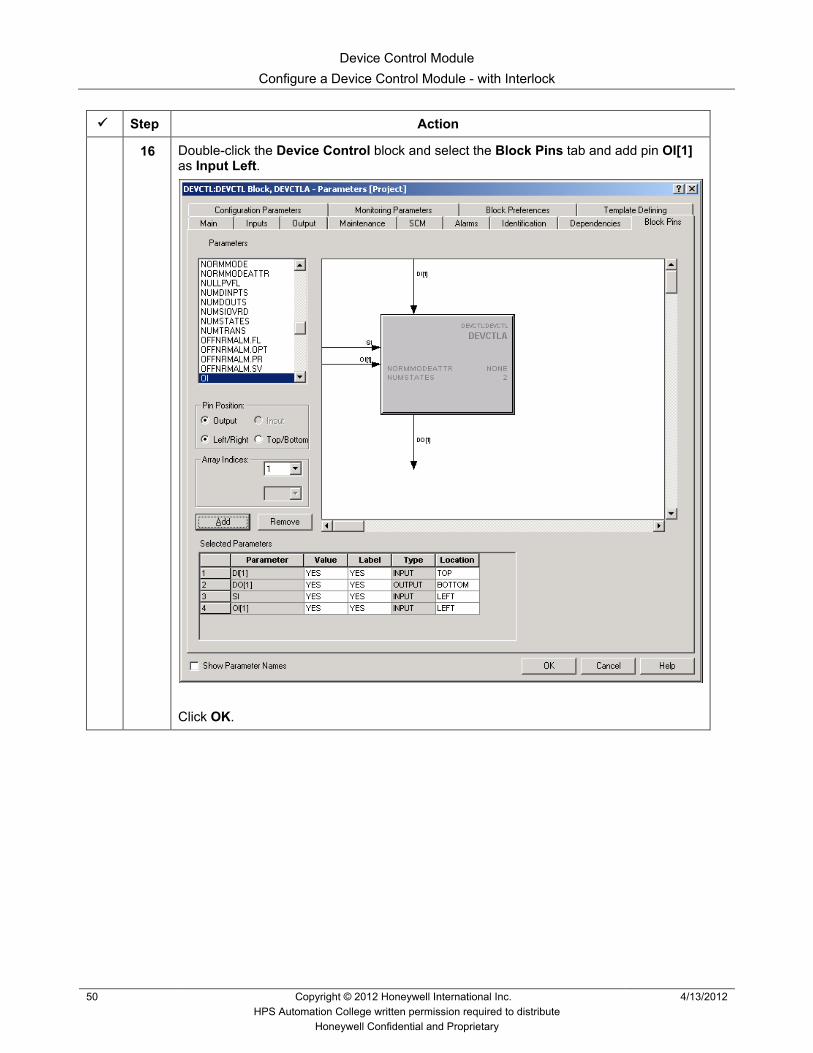
35 Wire parameter 11_HS63.HI. PVFL (PV for C300) to the IN[1] of ORA.
36 Save and close 11_HS62.
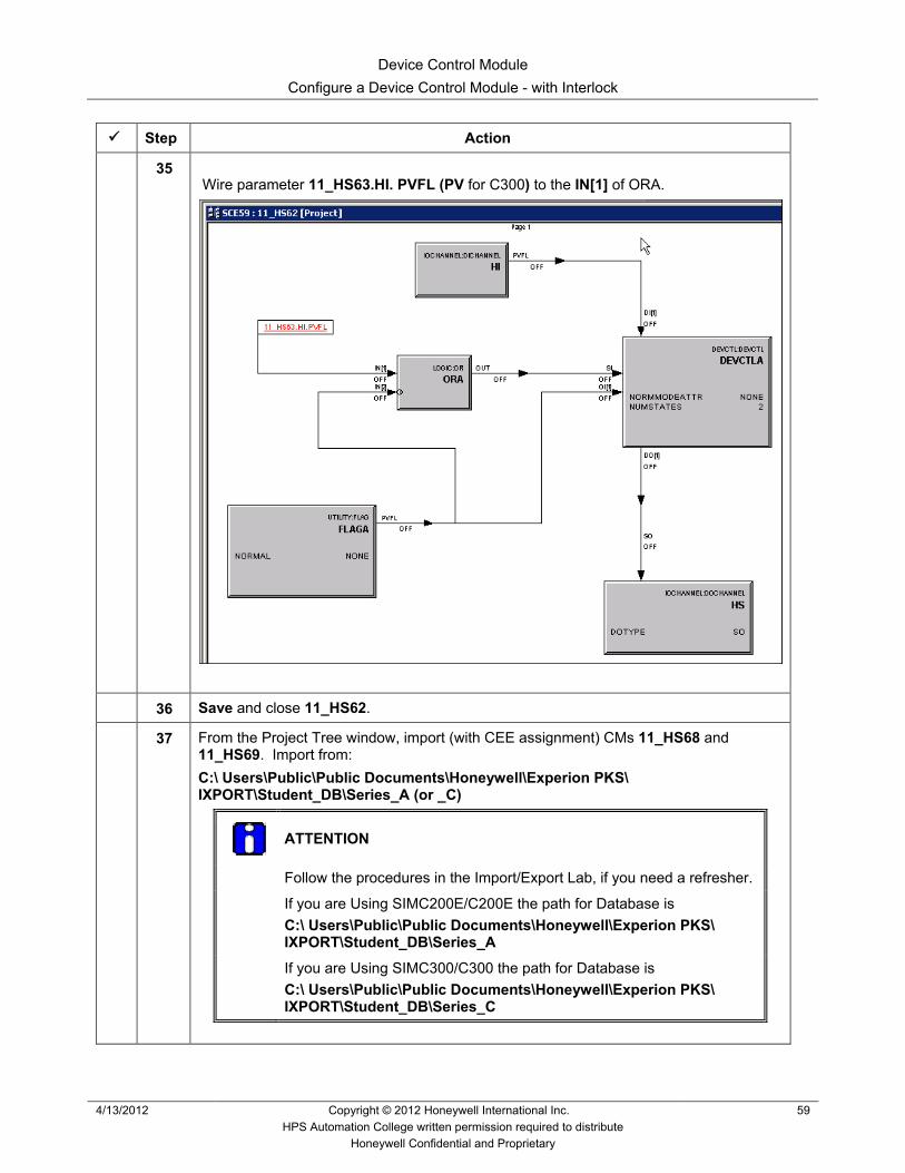
37 From the Project Tree window, import (with CEE assignment) CMs 11_HS68 and 11_HS69. Import from: C:\ Users\Public\Public Documents\Honeywell\Experion PKS\ IXPORT\Student_DB\Series_A (or _C)
ATTENTION
Follow the procedures in the Import/Export Lab, if you need a refresher.
If you are Using SIMC200E/C200E the path for Database is C:\ Users\Public\Public Documents\Honeywell\Experion PKS\ IXPORT\Student_DB\Series_A
If you are Using SIMC300/C300 the path for Database is C:\ Users\Public\Public Documents\Honeywell\Experion PKS\ IXPORT\Student_DB\Series_C

Device Control Module Configure a Device Control Module - with Interlock
60 Copyright © 2012 Honeywell International Inc. 4/13/2012 HPS Automation College written permission required to distribute
Honeywell Confidential and Proprietary
Step Action
38 Open the Project Tree window and verify that the Parent asset of 11_HS68 and 11_HS69 is Pumps_C11. If not, change it to Pumps_C11.
39 Download (with activation) 11_HS62, 11_HS63, 11_HS68, 11_HS69.
40 Use the Monitoring Tree window to verify all the CMs are active (green).
41 Open the Debutanizer_123 graphics on Station. If the graphics already loaded then reload the page so that new points are recognized. • All four pumps are OFF (Red)
42 Select the ON command for the pumps in the combo box.
• P62 and P68 are ON (green) • If P62 and P68 fail – which they will after sometime (up to 60 seconds) because of
the simulation in Tie_Back_New, then P63 and P69 will be commanded to start • After P62 and P68 have been commanded to start, it will be at least 20 seconds
before P63 and P69 are commanded to start because of the OnDelay function blocks in P63 and P69
• Therefore, after P62 and P68 turn on, it can be from 20 to 80 seconds (plus screen update) before P63 and P69 turn on.
• This happens because P62 feedback indicates that DI(1) is not ON within 20 sec after the Operator issues a start command