Development of Ultrasound Based Techniques for Measuring ...Techniques for Measuring Skeletal Muscle...
39
Development of Ultrasound Based Techniques for Measuring Skeletal Muscle Motion Jason Silver August 26, 2009
Transcript of Development of Ultrasound Based Techniques for Measuring ...Techniques for Measuring Skeletal Muscle...

Development of Ultrasound Based
Techniques for Measuring
Skeletal Muscle Motion
Jason Silver
August 26, 2009

Presentation Outline
Introduction
Thesis Objectives
Mathematical Model and Principles
Methods of Muscle Motion Measurement and Motion
Artifact Removal
Simulation Environment and Experiments
In Vivo Experiments
Conclusion
Future Work

Introduction
The musculature of the body has a great deal to do with
the overall health of an individual
– Athletic injury
– Muscular disorder
Understanding the physical properties of muscles and
how and why they move is of ongoing interest to many
medical practitioners
– Increasing the amount and type of information that can be measured
could lead to a much better understanding of the musculature and its
general effect on well-being
Thesis Objectives
Design and implement ultrasonic techniques to study
human skeletal muscle capable of measuring:
– Internal tissue displacement and velocity
Remove the effect of motion artifacts
– Relative strain information of the tissue being imaged
Design phantom simulation environment to test
methodology
Perform phantom simulation and in vivo testing of
techniques
Skeletal Muscle
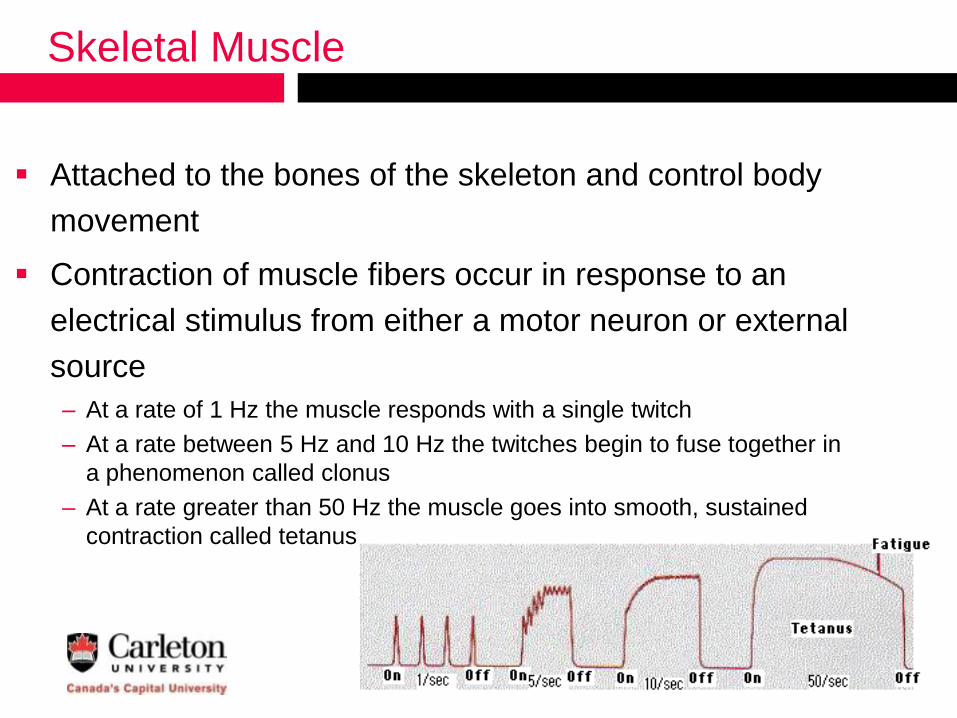
Attached to the bones of the skeleton and control body
movement
Contraction of muscle fibers occur in response to an
electrical stimulus from either a motor neuron or external
source
– At a rate of 1 Hz the muscle responds with a single twitch
– At a rate between 5 Hz and 10 Hz the twitches begin to fuse together in
a phenomenon called clonus
– At a rate greater than 50 Hz the muscle goes into smooth, sustained
contraction called tetanus
Current Methods to Measure Muscle Motion
Electromyography (EMG)
– Measures electric current resulting from muscle contraction with skin surface
or needle electrode
– EMG data is a summation of the electrical signals from under the electrode
Mechanomyography (MMG)
– Measures the mechanical motion resulting from a muscle contraction
– Most commonly done with skin surface mounted accelerometers
Magnetic Resonance Imaging (MRI)
– Most commonly used to measure tissue strain
Ultrasound (US)
– Most commonly used to track tissue motion and measure strain
– Theoretically capable of both internal and external measurements
» Not limited to surface motion or summations

Ultrasound Principles
Transducer is excited on a
repetitive basis (PRF)
– Image created based on received echo
Three major imaging modalities:
– A-mode: amplitude or envelope signal from
a single transducer usually displayed on an
oscilloscope
– M-mode: A-mode scan lines from a single
transducer are converted into grey scale
and used as columns of an image
– B-Mode: A-mode scan lines from multiple
adjacent transducers are converted into
grey scale and used as columns of an
image

Ultrasound Principles
M-Mode B-Mode
Ultrasound Hardware
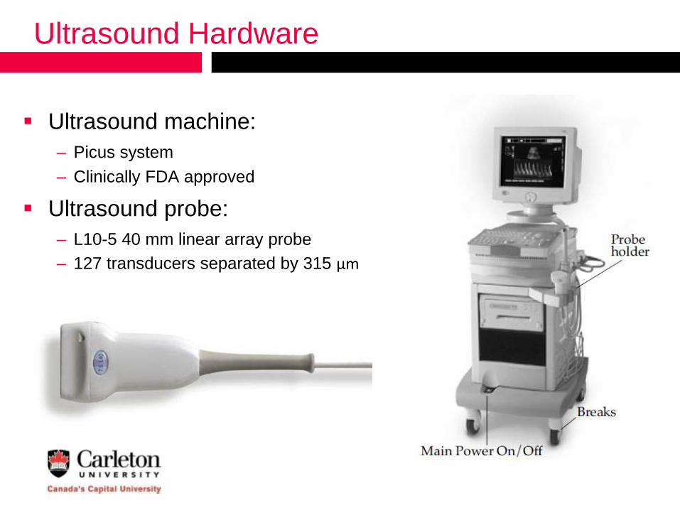
Ultrasound machine:
– Picus system
– Clinically FDA approved
Ultrasound probe:
– L10-5 40 mm linear array probe
– 127 transducers separated by 315 µm

Reference Frame and Coordinate System
Ultrasound probe reference frame places coordinate
system origin at the surface of probe
– All motion is relative to the surface of the probe
Displacement in a direction towards the probe is negative and away
from the probe is positive
Displacement magnitude increases with respect to depth for a uniform
object under a constant, external force applied at the surface of the
probe
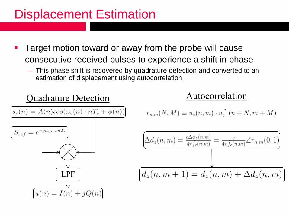
Displacement Estimation
Target motion toward or away from the probe will cause
consecutive received pulses to experience a shift in phase
– This phase shift is recovered by quadrature detection and converted to an estimation of displacement using autocorrelation
LPF
Quadrature Detection Autocorrelation

Strain Estimation
Axial strain is a measure of the relative deformation of an
object and can be estimated by the spatial gradient of
displacement in the axial direction

Global Surface Motion
External motion occurs due to motion of the probe or
object being imaged
– Classified as artifact motion
Estimated by ideally fixing the probe to the object surface
and measuring the change in distance between the probe
and bone surface

Internal Tissue Motion
Internal motion occurs and originates within the object being imaged– Ideally no probe or external object motion should occur
The distance between the probe and bone surface must remain
constant in order to accurately estimate internal motion

Removing Motion Artifacts
Practically very difficult to keep a fixed distance between
probe and bone surface
– Bone boundary algorithm for motion artifact removal fixes the distance
between probe and bone surface regardless of the motion occurring
during data acquisition
– Bone is uncompressible and should not experience motion due to
muscle contraction. Any motion measured at the surface of the bone can
be assumed to be a result of a motion artifact
The three main components of the algorithm are:
– Measurement procedure
– Bone boundary tracking
– Depth scaling and motion artifact subtraction

Measurement Procedure
Divided the experimental procedure into two different
sections of collected data:
– Reference Section
Contains only external motion caused by pushing probe down into the
object being imaged
Used for depth scaling
– Experimental Section
Contains desired experimental signals
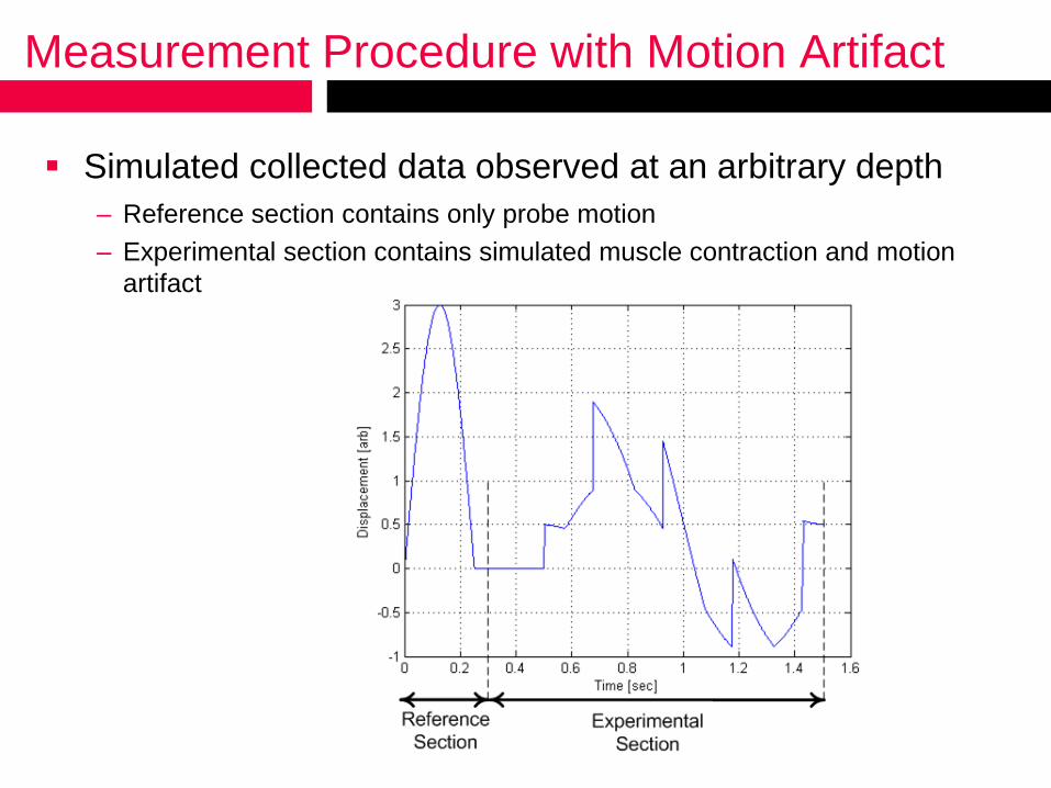
Measurement Procedure with Motion Artifact
Simulated collected data observed at an arbitrary depth
– Reference section contains only probe motion
– Experimental section contains simulated muscle contraction and motion
artifact

Bone Boundary Echo Tracking and Depth Scaling
Bone boundary tracked to determine motion artifact
– Initial location found with demodulated baseband envelope and B-mode
image
– Windowed peak tracking algorithm tracks bone boundary over all time
Magnitude of displacement at bone boundary scaled with
respect to depth
– Scaled by peak-to-peak displacement
magnitude comparison in reference
section
– Scaled displacement subtracted to
obtain internal displacement
estimation

Simulation System: Phantom Development
Compressible internal tissues simulated with agar
– Agar powder mixed with water
The higher the agar concentration, the stiffer the solid
» 1 w% agar resembles fat
» 2 w% agar resembles resting muscle
» 3 w% agar resembles contracted muscle
– Carbon particles added to act as ultrasound
scatterers
Uncompressible bone simulated
with plexiglas
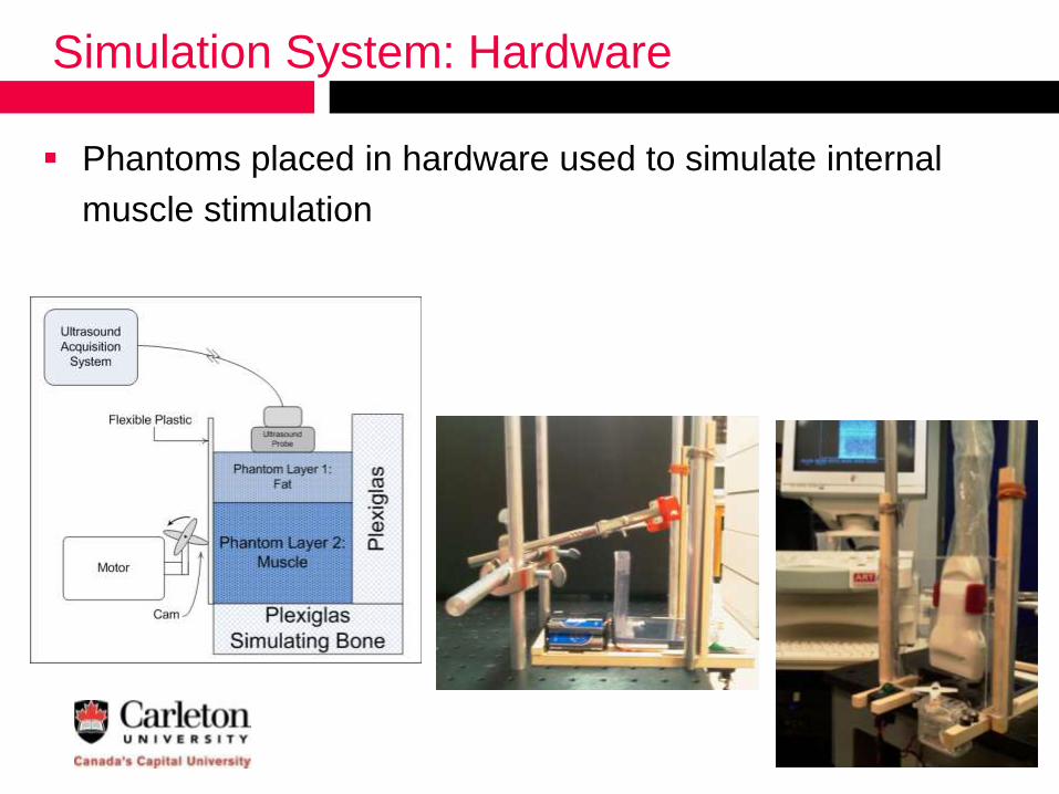
Simulation System: Hardware
Phantoms placed in hardware used to simulate internal
muscle stimulation

Simulation Experimental Strain Results
M-mode data of 1 w% and 3 w%
two layer agar phantom
0

Simulated Muscle Contraction Experimental Results
M-mode data of 19 mm thick 3 w%
single layer agar phantom
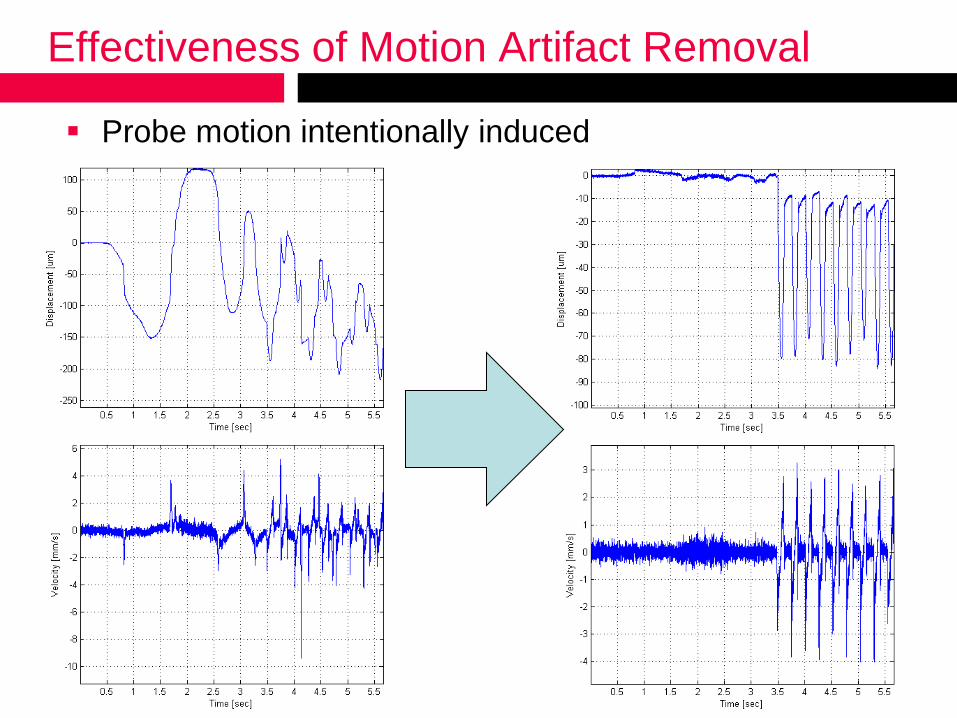
Effectiveness of Motion Artifact Removal
Probe motion intentionally induced

In Vivo Experimental Design
Forearm muscle stimulated with
EMS at a variety of repetition rates
ranging from 2 Hz to 12 Hz
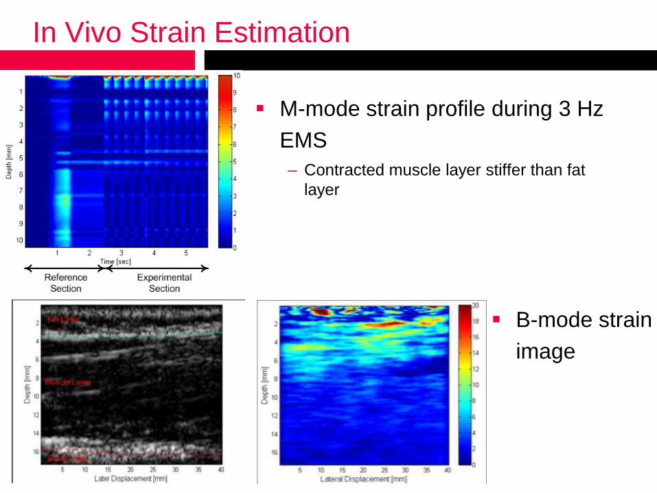
In Vivo Strain Estimation
M-mode strain profile during 3 Hz
EMS
– Contracted muscle layer stiffer than fat
layer
B-mode strain
image
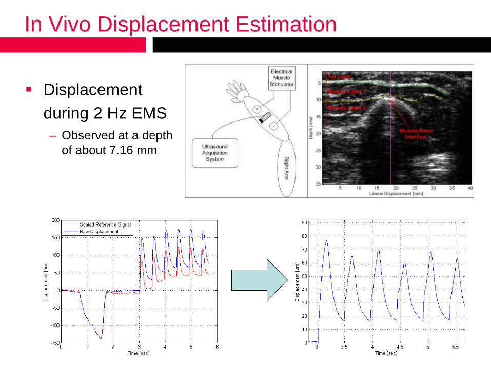
In Vivo Displacement Estimation
Displacement
during 2 Hz EMS
– Observed at a depth
of about 7.16 mm
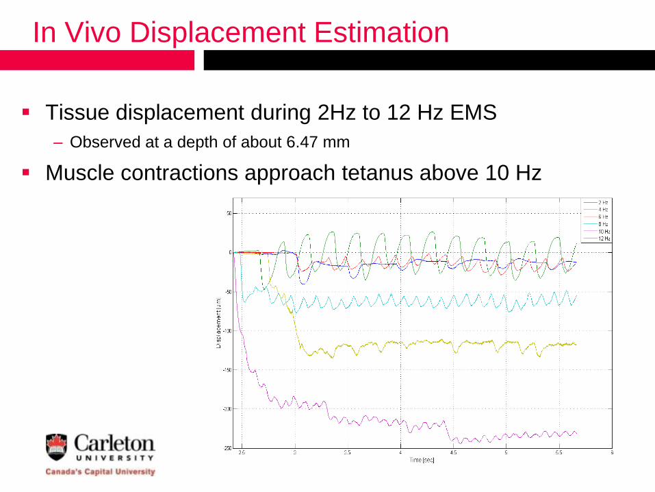
In Vivo Displacement Estimation
Tissue displacement during 2Hz to 12 Hz EMS
– Observed at a depth of about 6.47 mm
Muscle contractions approach tetanus above 10 Hz

Conclusion
Designed and implemented a system to study human
skeletal muscle capable of estimating:
– Internal tissue displacement and velocity
– Relative strain
Designed and implemented an algorithm to remove the
effects of motion artifacts during internal tissue
measurements
Designed and tested a phantom simulation system
– Tissue mimicking phantoms
– Hardware to simulate electrical muscle stimulation
Performed phantom simulation and in vivo experiments
using the developed system

Future Work
Develop a more precise and controllable method to
create tissue mimicking phantoms
Perform additional in vivo experiments to better
understand skeletal muscle
Improve measurement accuracy

Questions?
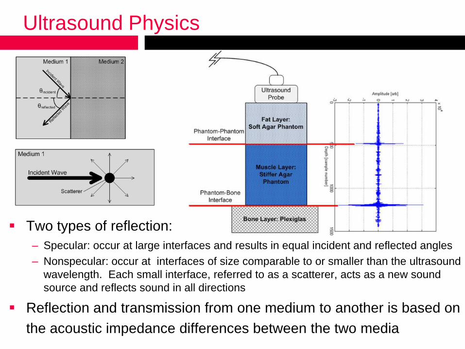
Ultrasound Physics
Two types of reflection:
– Specular: occur at large interfaces and results in equal incident and reflected angles
– Nonspecular: occur at interfaces of size comparable to or smaller than the ultrasound
wavelength. Each small interface, referred to as a scatterer, acts as a new sound
source and reflects sound in all directions
Reflection and transmission from one medium to another is based on
the acoustic impedance differences between the two media
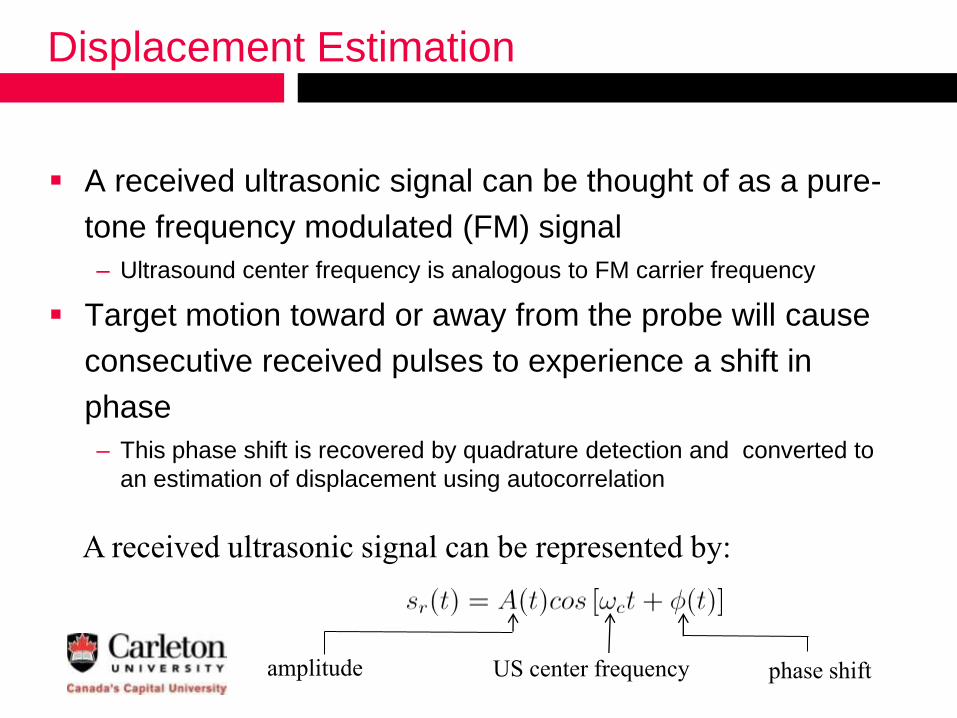
Displacement Estimation
A received ultrasonic signal can be thought of as a pure-
tone frequency modulated (FM) signal
– Ultrasound center frequency is analogous to FM carrier frequency
Target motion toward or away from the probe will cause
consecutive received pulses to experience a shift in
phase
– This phase shift is recovered by quadrature detection and converted to
an estimation of displacement using autocorrelation
A received ultrasonic signal can be represented by:
phase shiftUS center frequencyamplitude
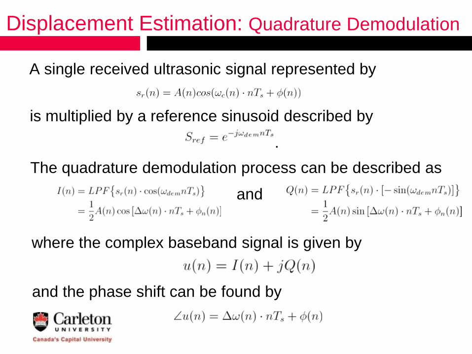
Displacement Estimation: Quadrature Demodulation
A single received ultrasonic signal represented by
is multiplied by a reference sinusoid described by
.
The quadrature demodulation process can be described as
and
where the complex baseband signal is given by
and the phase shift can be found by
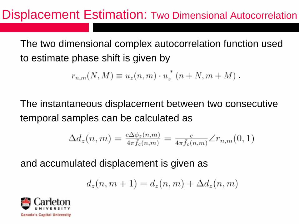
Displacement Estimation: Two Dimensional Autocorrelation
The two dimensional complex autocorrelation function used
to estimate phase shift is given by
.
The instantaneous displacement between two consecutive
temporal samples can be calculated as
and accumulated displacement is given as

Bone Boundary Method of Motion Artifact Removal
Simulated collected data
observed at an arbitrary depth
– Reference section contains only
probe motion
– Experimental section contains
simulated muscle contraction and
motion artifact

Strain Estimation ®
Axial strain is a measure of the relative deformation of an
object and can be estimated by
Stiffer tissue shows less
strain than softer tissue
under equally applied
forces

Motion Definitions ®
External motion occurs due to motion of the probe or object
being imaged
– Classified as artifact motion
Internal motion occurs and originates within the object being
imaged
– Ideally no probe or external object motion should occur

Extra Slide for explanation
Actual center frequency cannot be exactly known due to
spatial and temporal fluctuation and is therefore estimated
as

Extra slide for explanation
Accuracy evaluation