
Development of Torque Vectoring Differential control ECU · turning performance, ... (Torque...
6
28 Abstract Development of Torque Vectoring Differential control ECU
Transcript of Development of Torque Vectoring Differential control ECU · turning performance, ... (Torque...
28
LEXUS released IS F in 2007 and LFA in 2010 to establish a sporty image leading the LEXUS brand. To further improve the brand power and the recognition of LEXUS, LEXUS started selling a new F model: LEXUS RC F, developed with the concept of ‘sport car to be enjoyed by all enthusiasts - no matter what their level of expertise.’ To provide excellent turning performance, LEXUS engineers developed and adopted Torque Vectoring Differential (TVD) technology for a front-engine rear-wheel-drive (FR) vehicle for the first time in the world (first TVD for Toyota Motor Corporation) that performs electronic control to actively ‘transfer’ torque to right and left rear wheels. The TVD technology contributes to the implementation of ideal vehicle behavior for an FR vehicle, achieving both of a light steering feeling and a stable feeling during middle/high speed traveling. FUJITSU TEN developed the ECU (TVD ECU) that controls a torque vectoring module for right/left torque distribution. This paper introduces the outline, configuration and features of the TVD ECU and its actuator control method.
Abstract
Katsumi TSUCHIDA
Makoto NAGAMOTO
Shinji TAKEMARU
Masato HISANAGA
Ryosuke KUROKAWA
Takafumi SHINOHARA
Development of Torque Vectoring Differential control ECU
FUJITSU TEN TECH. J. NO.40(2014)
Development of Torque Vectoring Differential control ECU
29
1. Introduction
Generally, cars have differential gears in driving wheels, and the differential gears absorb a speed differ-ence between inner and outer wheels during turning so that smooth turning can be realized. On the other hand, however, the differential gear has a drawback that the tire starts to slip when no load is applied to the wheels. The traction drop phenomenon due to inner wheel load loss at the time of derailing, stacking on the off-road or turning at a high speed corresponds to this phenomenon. With regard to this phenomenon, systems securing the traction by differential limitation such as the differential lock mechanism or the limited slip differential (LSD) are industrialized. Although these are systems operating only under specific conditions, the TVD (Torque Vectoring Differential), which will be introduced in this paper, is the system which actively changes (transfers) torques gener-ated in right and left driving wheels by electric control and forcibly generates a yaw moment of the vehicle due to a speed difference between right and left wheels so that the turning performance is improved. As the system for commercial vehicles, this system was introduced in the latter half of 90's at the earliest, and Fig, 1 shows the sys-tem adoption situations of companies.
It can be understood from the figure that, recently, the TVD adoption by companies has been promoted, that the market focuses on the turning performance, and that the TVD is adopted for four-wheel-drive cars whose vehicle weight is heavy and which has a strong understeer ten-dency. In addition, the hydraulic type TVD is often adopt-ed as a mechanism.
The TVD adopted for RC F this time is the first TVD in the world for a front-engine rear-wheel-drive (FR) vehi-cle (this is the first TVD adopted by Toyota Motor Corporation), and is the electric type TVD using a three-phase brushless motor as a mechanism. The TVD is superior in that it is highly responsive compared to the hydraulic type broadly adopted by other companies, the operation temperature range is broad, and the control at high accuracy is possible.
In this paper, the system overview, the ECU configu-ration and actuator control will be explained.
2. System Overview
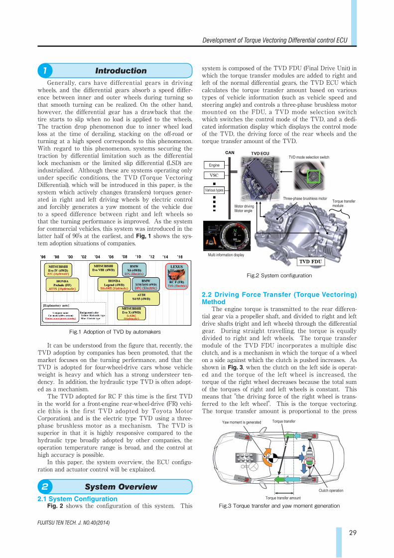
2.1 System ConfigurationFig. 2 shows the configuration of this system. This
system is composed of the TVD FDU (Final Drive Unit) in which the torque transfer modules are added to right and left of the normal differential gears, the TVD ECU which calculates the torque transfer amount based on various types of vehicle information (such as vehicle speed and steering angle) and controls a three-phase brushless motor mounted on the FDU, a TVD mode selection switch which switches the control mode of the TVD, and a dedi-cated information display which displays the control mode of the TVD, the driving force of the rear wheels and the torque transfer amount of the TVD.
2.2 Driving Force Transfer (Torque Vectoring) Method
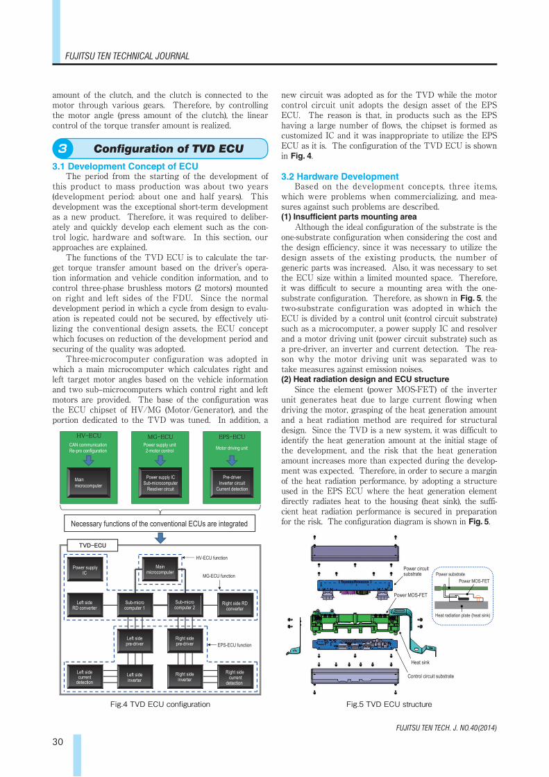
The engine torque is transmitted to the rear differen-tial gear via a propeller shaft, and divided to right and left drive shafts (right and left wheels) through the differential gear. During straight travelling, the torque is equally divided to right and left wheels. The torque transfer module of the TVD FDU incorporates a multiple disc clutch, and is a mechanism in which the torque of a wheel on a side against which the clutch is pushed increases. As shown in Fig. 3, when the clutch on the left side is operat-ed and the torque of the left wheel is increased, the torque of the right wheel decreases because the total sum of the torques of right and left wheels is constant. This means that "the driving force of the right wheel is trans-ferred to the left wheel". This is the torque vectoring. The torque transfer amount is proportional to the press
Fig.1 Adoption of TVD by automakers
Fig.2 System configuration
Engine
Various types
Multi information display
Motor drivingMotor angle
TVD mode selection switch
Three-phase brushless motor Torque transfer module
Introduction1
System Overview2
Fig.3 Torque transfer and yaw moment generation
Yaw moment is generated Torque transfer
Torque transfer amount
Clutch operation
FUJITSU TEN TECH. J. NO.40(2014)
FUJITSU TEN TECHNICAL JOURNAL
30
amount of the clutch, and the clutch is connected to the motor through various gears. Therefore, by controlling the motor angle (press amount of the clutch), the linear control of the torque transfer amount is realized.
3. Configuration of TVD ECU
3.1 Development Concept of ECUThe period from the starting of the development of
this product to mass production was about two years (development period: about one and half years). This development was the exceptional short-term development as a new product. Therefore, it was required to deliber-ately and quickly develop each element such as the con-trol logic, hardware and software. In this section, our approaches are explained.
The functions of the TVD ECU is to calculate the tar-get torque transfer amount based on the driver's opera-tion information and vehicle condition information, and to control three-phase brushless motors (2 motors) mounted on right and left sides of the FDU. Since the normal development period in which a cycle from design to evalu-ation is repeated could not be secured, by effectively uti-lizing the conventional design assets, the ECU concept which focuses on reduction of the development period and securing of the quality was adopted.
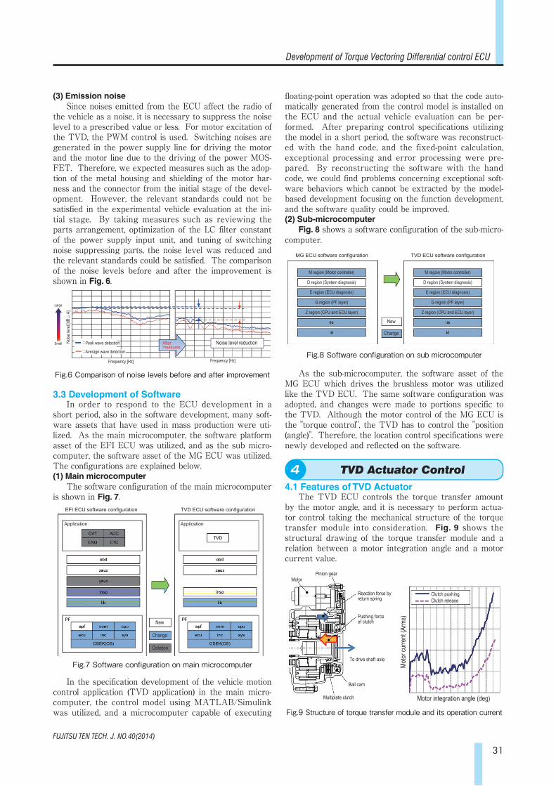
Three-microcomputer configuration was adopted in which a main microcomputer which calculates right and left target motor angles based on the vehicle information and two sub–microcomputers which control right and left motors are provided. The base of the configuration was the ECU chipset of HV/MG (Motor/Generator), and the portion dedicated to the TVD was tuned. In addition, a
new circuit was adopted as for the TVD while the motor control circuit unit adopts the design asset of the EPS ECU. The reason is that, in products such as the EPS having a large number of flows, the chipset is formed as customized IC and it was inappropriate to utilize the EPS ECU as it is. The configuration of the TVD ECU is shown in Fig. 4.
3.2 Hardware DevelopmentBased on the development concepts, three items,
which were problems when commercializing, and mea-sures against such problems are described.(1) Insufficient parts mounting area
Although the ideal configuration of the substrate is the one-substrate configuration when considering the cost and the design efficiency, since it was necessary to utilize the design assets of the existing products, the number of generic parts was increased. Also, it was necessary to set the ECU size within a limited mounted space. Therefore, it was difficult to secure a mounting area with the one-substrate configuration. Therefore, as shown in Fig. 5, the two-substrate configuration was adopted in which the ECU is divided by a control unit (control circuit substrate) such as a microcomputer, a power supply IC and resolver and a motor driving unit (power circuit substrate) such as a pre-driver, an inverter and current detection. The rea-son why the motor driving unit was separated was to take measures against emission noises.(2) Heat radiation design and ECU structure
Since the element (power MOS-FET) of the inverter unit generates heat due to large current flowing when driving the motor, grasping of the heat generation amount and a heat radiation method are required for structural design. Since the TVD is a new system, it was difficult to identify the heat generation amount at the initial stage of the development, and the risk that the heat generation amount increases more than expected during the develop-ment was expected. Therefore, in order to secure a margin of the heat radiation performance, by adopting a structure used in the EPS ECU where the heat generation element directly radiates heat to the housing (heat sink), the suffi-cient heat radiation performance is secured in preparation for the risk. The configuration diagram is shown in Fig. 5.
Fig.4 TVD ECU configuration Fig.5 TVD ECU structure
TVD-ECU
HV-ECU MG-ECU EPS-ECU
Left side current
detection Left side inverter
Right side inverter
Right side current
detection
CAN communication Re-pro configuration
Main microcomputer
Power supply unit 2-motor control Motor driving unit
Power supply IC Sub-microcomputer
Resolver circuit
Pre-driver Inverter circuit
Current detection
Necessary functions of the conventional ECUs are integrated
Power supplyIC
Left side RD converter
Sub-micro computer 1
Left side pre-driver
Main microcomputer
Sub-micro computer 2
Right side pre-driver
HV-ECU function
MG-ECU function
EPS-ECU function
Right side RD converter
Power circuit substrate
Power MOS-FET
Heat sink
Control circuit substrate
Power substrate Power MOS-FET
Heat radiation plate (heat sink)
Configuration of TVD ECU3
FUJITSU TEN TECH. J. NO.40(2014)
Development of Torque Vectoring Differential control ECU
31
(3) Emission noiseSince noises emitted from the ECU affect the radio of
the vehicle as a noise, it is necessary to suppress the noise level to a prescribed value or less. For motor excitation of the TVD, the PWM control is used. Switching noises are generated in the power supply line for driving the motor and the motor line due to the driving of the power MOS-FET. Therefore, we expected measures such as the adop-tion of the metal housing and shielding of the motor har-ness and the connector from the initial stage of the devel-opment. However, the relevant standards could not be satisfied in the experimental vehicle evaluation at the ini-tial stage. By taking measures such as reviewing the parts arrangement, optimization of the LC filter constant of the power supply input unit, and tuning of switching noise suppressing parts, the noise level was reduced and the relevant standards could be satisfied. The comparison of the noise levels before and after the improvement is shown in Fig. 6.
3.3 Development of SoftwareIn order to respond to the ECU development in a
short period, also in the software development, many soft-ware assets that have used in mass production were uti-lized. As the main microcomputer, the software platform asset of the EFI ECU was utilized, and as the sub micro-computer, the software asset of the MG ECU was utilized. The configurations are explained below.(1) Main microcomputer
The software configuration of the main microcomputer is shown in Fig. 7.
In the specification development of the vehicle motion control application (TVD application) in the main micro-computer, the control model using MATLAB/Simulink was utilized, and a microcomputer capable of executing
floating-point operation was adopted so that the code auto-matically generated from the control model is installed on the ECU and the actual vehicle evaluation can be per-formed. After preparing control specifications utilizing the model in a short period, the software was reconstruct-ed with the hand code, and the fixed-point calculation, exceptional processing and error processing were pre-pared. By reconstructing the software with the hand code, we could find problems concerning exceptional soft-ware behaviors which cannot be extracted by the model-based development focusing on the function development, and the software quality could be improved.(2) Sub-microcomputer
Fig. 8 shows a software configuration of the sub-micro-computer.
As the sub-microcomputer, the software asset of the MG ECU which drives the brushless motor was utilized like the TVD ECU. The same software configuration was adopted, and changes were made to portions specific to the TVD. Although the motor control of the MG ECU is the "torque control", the TVD has to control the "position (angle)". Therefore, the location control specifications were newly developed and reflected on the software.
4. TVD Actuator Control
4.1 Features of TVD ActuatorThe TVD ECU controls the torque transfer amount
by the motor angle, and it is necessary to perform actua-tor control taking the mechanical structure of the torque transfer module into consideration. Fig. 9 shows the structural drawing of the torque transfer module and a relation between a motor integration angle and a motor current value.
Fig.6 Comparison of noise levels before and after improvement
Fig.7 Software configuration on main microcomputer
Fig.8 Software configuration on sub microcomputer
Large
Small Noise
leve
l [dBμ
A]
Peak wave detection
Average wave detection
Frequency [Hz] Frequency [Hz]
Noise level reduction After measures
EFI ECU software configuration
Application
TVD ECU software configuration
Application
New
Change
Deletion
MG ECU software configuration
M region (Motor controller)
D region (System diagnosis)
E region (ECU diagnosis)
G region (PF layer)
Z region (CPU and ECU layer)
TVD ECU software configuration
M region (Motor controller)
D region (System diagnosis)
E region (ECU diagnosis)
G region (PF layer)
Z region (CPU and ECU layer)
New
Change
Fig.9 Structure of torque transfer module and its operation current
MotorPinion gear
Reaction force by return spring
Pushing forceof clutch
To drive shaft axle
Ball cam
Multiplate clutch
Clutch pushingClutch release
Motor
curre
nt (A
rms)
Motor integration angle (deg)
TVD Actuator Control4
FUJITSU TEN TECH. J. NO.40(2014)
FUJITSU TEN TECHNICAL JOURNAL
32
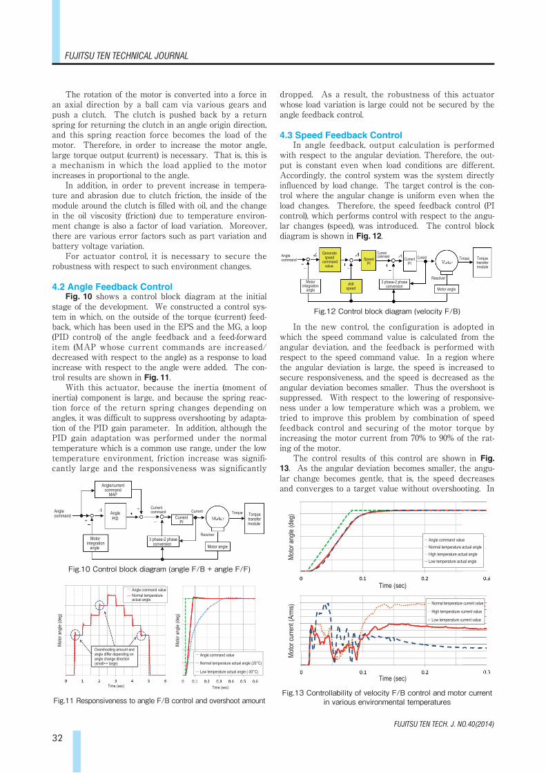
The rotation of the motor is converted into a force in an axial direction by a ball cam via various gears and push a clutch. The clutch is pushed back by a return spring for returning the clutch in an angle origin direction, and this spring reaction force becomes the load of the motor. Therefore, in order to increase the motor angle, large torque output (current) is necessary. That is, this is a mechanism in which the load applied to the motor increases in proportional to the angle.
In addition, in order to prevent increase in tempera-ture and abrasion due to clutch friction, the inside of the module around the clutch is filled with oil, and the change in the oil viscosity (friction) due to temperature environ-ment change is also a factor of load variation. Moreover, there are various error factors such as part variation and battery voltage variation.
For actuator control, it is necessary to secure the robustness with respect to such environment changes.
4.2 Angle Feedback ControlFig. 10 shows a control block diagram at the initial
stage of the development. We constructed a control sys-tem in which, on the outside of the torque (current) feed-back, which has been used in the EPS and the MG, a loop (PID control) of the angle feedback and a feed-forward item (MAP whose current commands are increased/decreased with respect to the angle) as a response to load increase with respect to the angle were added. The con-trol results are shown in Fig. 11.
With this actuator, because the inertia (moment of inertia) component is large, and because the spring reac-tion force of the return spring changes depending on angles, it was difficult to suppress overshooting by adapta-tion of the PID gain parameter. In addition, although the PID gain adaptation was performed under the normal temperature which is a common use range, under the low temperature environment, friction increase was signifi-cantly large and the responsiveness was significantly
dropped. As a result, the robustness of this actuator whose load variation is large could not be secured by the angle feedback control.
4.3 Speed Feedback ControlIn angle feedback, output calculation is performed
with respect to the angular deviation. Therefore, the out-put is constant even when load conditions are different. Accordingly, the control system was the system directly influenced by load change. The target control is the con-trol where the angular change is uniform even when the load changes. Therefore, the speed feedback control (PI control), which performs control with respect to the angu-lar changes (speed), was introduced. The control block diagram is shown in Fig. 12.
In the new control, the configuration is adopted in which the speed command value is calculated from the angular deviation, and the feedback is performed with respect to the speed command value. In a region where the angular deviation is large, the speed is increased to secure responsiveness, and the speed is decreased as the angular deviation becomes smaller. Thus the overshoot is suppressed. With respect to the lowering of responsive-ness under a low temperature which was a problem, we tried to improve this problem by combination of speed feedback control and securing of the motor torque by increasing the motor current from 70% to 90% of the rat-ing of the motor.
The control results of this control are shown in Fig. 13. As the angular deviation becomes smaller, the angu-lar change becomes gentle, that is, the speed decreases and converges to a target value without overshooting. In
Fig.10 Control block diagram (angle F/B + angle F/F)
Fig.11 Responsiveness to angle F/B control and overshoot amount
Fig.12 Control block diagram (velocity F/B)
Angle command
Angle/current command
MAP
AnglePID
Motor integration
angle
Current command
3 phase-2 phaseconversion
CurrentPI
Current
Resolver
Motor angle
Torque Torquetransfermodule
Motor
angle
(deg
)
Motor
angle
(deg
)
Time (sec) Time (sec)
Overshooting amount and angle differ depending on angle change direction(small↔ large)
---- Angle command value ---- Normal temperature
actual angle
---- Angle command value
---- Normal temperature actual angle (20°C)
---- Low temperature actual angle (-30°C)
Speed PI
TorqueAngle command
Motor integration
angle
Generate speed
commandvalue
d/dt speed
Current command
3 phase-2 phase conversion
Current Current PI
Resolver
Motor angle
Torquetransfermodule
Fig.13 Controllability of velocity F/B control and motor current in various environmental temperatures
Motor
angle
(deg
)
Time (sec)
Time (sec)
Motor
curre
nt (A
rms) --- Normal temperature current value
--- High temperature current value --- Low temperature current value
--- Angle command value --- Normal temperature actual angle --- High temperature actual angle --- Low temperature actual angle
FUJITSU TEN TECH. J. NO.40(2014)
Development of Torque Vectoring Differential control ECU
33
addition, when comparing the normal temperature and the low temperature, the angular changes draw almost the same locus. However, we can read that the torque is secured by increasing the motor current with respect to increase in motor load due to friction increase at the low temperature.
From this result, it can be said that the speed feed-back absorbs the influences of load variations, uniform angular change is realized even when the load is changed, and the robustness with respect to load variation factors (temperature, voltage and part variations) could be secured.
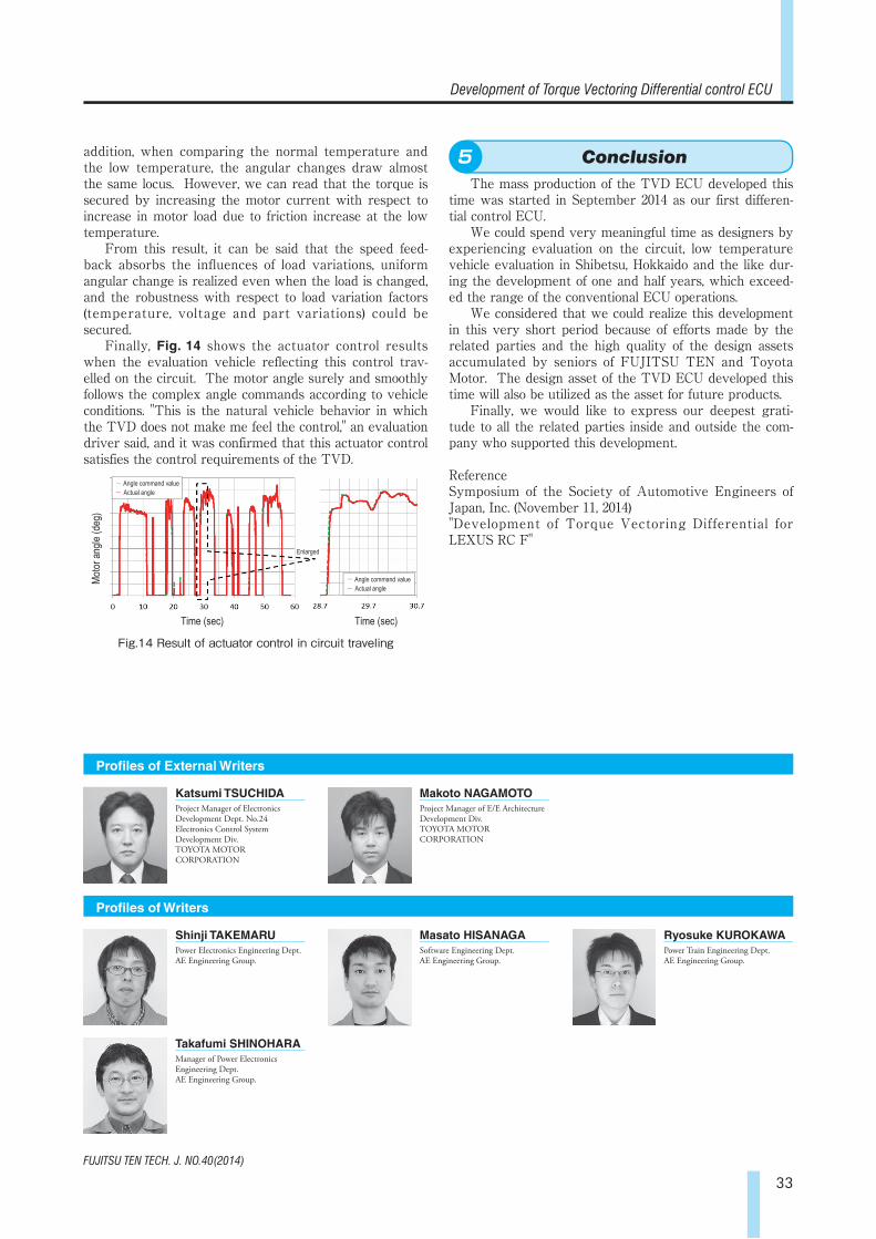
Finally, Fig. 14 shows the actuator control results when the evaluation vehicle reflecting this control trav-elled on the circuit. The motor angle surely and smoothly follows the complex angle commands according to vehicle conditions. "This is the natural vehicle behavior in which the TVD does not make me feel the control," an evaluation driver said, and it was confirmed that this actuator control satisfies the control requirements of the TVD.
5. Conclusion
The mass production of the TVD ECU developed this time was started in September 2014 as our first differen-tial control ECU.
We could spend very meaningful time as designers by experiencing evaluation on the circuit, low temperature vehicle evaluation in Shibetsu, Hokkaido and the like dur-ing the development of one and half years, which exceed-ed the range of the conventional ECU operations.
We considered that we could realize this development in this very short period because of efforts made by the related parties and the high quality of the design assets accumulated by seniors of FUJITSU TEN and Toyota Motor. The design asset of the TVD ECU developed this time will also be utilized as the asset for future products.
Finally, we would like to express our deepest grati-tude to all the related parties inside and outside the com-pany who supported this development.
ReferenceSymposium of the Society of Automotive Engineers of Japan, Inc. (November 11, 2014)"Development of Torque Vectoring Differential for LEXUS RC F"
Fig.14 Result of actuator control in circuit traveling
Motor
angle
(deg
)
--- Angle command value --- Actual angle
--- Angle command value --- Actual angle
Time (sec) Time (sec)
Enlarged
Conclusion5
Profiles of Writers
Profiles of External Writers
Katsumi TSUCHIDAProject Manager of Electronics Development Dept. No.24Electronics Control System Development Div.TOYOTA MOTOR CORPORATION
Shinji TAKEMARUPower Electronics Engineering Dept.AE Engineering Group.
Takafumi SHINOHARAManager of Power Electronics Engineering Dept.AE Engineering Group.
Masato HISANAGASoftware Engineering Dept.AE Engineering Group.
Ryosuke KUROKAWAPower Train Engineering Dept.AE Engineering Group.
Makoto NAGAMOTOProject Manager of E/E Architecture Development Div.TOYOTA MOTOR CORPORATION


