DEVELOPMENT OF ROUND DIE FOR PRESS BRAKE MACHINE ...
32
iii DEVELOPMENT OF ROUND DIE FOR PRESS BRAKE MACHINE KHAIRUL SYAHMI BIN AHMAD A report submitted in fulfilment of the requirement for the award of the Diploma of Mechanical Engineering Faculty of Mechanical Engineering University Malaysia Pahang JANUARY 2012
-
Upload
hoangduong -
Category
Documents
-
view
215 -
download
0
Transcript of DEVELOPMENT OF ROUND DIE FOR PRESS BRAKE MACHINE ...

iii
DEVELOPMENT OF ROUND DIE FOR PRESS BRAKE MACHINE
KHAIRUL SYAHMI BIN AHMAD
A report submitted in fulfilment of the
requirement for the award of the Diploma
of Mechanical Engineering
Faculty of Mechanical Engineering
University Malaysia Pahang
JANUARY 2012

viii
ABSTRACT
The target of this project was to design and fabricate the round die with radius
10mm. To success this project, the important things is to design the round die via
Solidwork. After that, the mild steel materials were used in fabricate process based on
cutting, milling, and edm wire cut. The results show the parts can be combined with the
machine.

ix
ABSTRAK
Target projek ini adalah untuk merekea bentuk dan membuat die berbentuk
separuh bulat berdiameter 10mm. Untuk menjayakan projek ini,perkara utama yang
perlu diketahui ialah mengenai melukis die separuh bulat menggunakan solidwork.
Perkara seterusnya ialah material besi digunakan untuk membuat proses berdasarkan
pemotongan dan pengisaran. Keputusan dapat dilihat apabila die tersebut boleh di
gabungkan dengan mesin.

x
TABLE OF CONTENT
PAGE
SUPERVISOR’S DECLARATIO ii
STUDENT’S DECLARATION iv
ACKNOWLEDGEMENTS vi
ABSTRACT vii
ABSTRAK viii
TABLE OF CONTENT ix
LIST OF FIGURES xii

xi
CHAPTER TITLE PAGE
1 INTRODUCTION 1
1.1 Background 1
1.2 Project Objective 5
1.3 Project Scope 5
1.4 Project Planning 6
2 LITERATURE REVIEW 9
2.1 Introduction 9
2.2 About press brake machine 9
2.3 Types of brakes 11
2.4 Types of dies 13
2.5 Summary 15
3 PROJECT METHODOLOGY 16
3.1 Introduction 16
3.2 Design Process 16
3.3 Fabrication Process 17

xii
4 RESULTS AND DISCUSSION 20
4.1 Introduction 20
4.2 Processes 21
4.3 Step by step of the process 22
4.4 Result 26
4.5 Discussion 26
5 CONCLUSION 27
References 28
APPENDIX 29

xiii
LIST OF FIGURE
NO. OF FIGURE TITLE PAGE
1.1 SETS OF DIE 4
1.2 GANTT CHART 7
1.3 FLOW CHART 8
2.1 TRUMABEND MACHINE 10
2.2 BEND PROCESS 12
3.1 FRONT VIEW OF ROUND
DIE
17
3.2 SIDE VIEW OF ROUND
DIE
17
3.3 MILLING MACHINE 19
3.4 EDM WIE CUT MACHINE 19
4.1 FACE MILL 21

xiv
4.2 CUTTING PROCESS 23
4.3 CUTTING PROCESS 23

1
CHAPTER 1
1.1 BACKGROUND
Nowadays, lots of integrated modular products are built in variant of
function and shapes. These products are being used in many sectors in industry.
The product being use to make a curve on the sheet metal. Since quality is a basic
requirement for the design, providing clear manufacturability specifications and
proper quality product is important. The designer is must have the feedback from
consumers of creating the ideas of making their integrated modular product.
The design should have good performance in order to have zero problems
while using their products. In related to have the quality of the product, making the
integrated modular product design is also being focused on reducing the cost. This
is the main perception from the customers if they want to buy the current product.
This project will give more information background about the round dies. One
example of the product that using this round die to be produce is coin.
In addition to producing two books, they also penned a nice feature article for
the May 2005 issue of Numismatist ("The Saga of the 1870-S Silver Dollar"). In this
article the authors quoted a letter from Carson City Mint Superintendent Abraham Curry

2
to his colleague in San Francisco, Superintendent Oscar H. LaGrange, in which Curry
made reference to "silver-dollar radius plates." The authors stated that the research had
failed to turn up an explanation of this term. Since it have encountered the word "radius"
in reference to die preparation on a few occasions, the first impulse was to contact the
authors or draft a letter to the editor, but then it seemed that a more thorough look at the
subject might be in order.
Published references to round die are actually quite rare. The term has never
been, to the knowledge, explained in detail. Instead, what have found are passing
references, such as those found . Usually, these turn up in the writings of U. S. Mint
Chief Engraver Charles Barber (in office 1879-1917) or, less often, those of his
successor, George T. Morgan (1917-25). More must be inferred from their indirect usage
of the term than is actually stated. The closest thing that found in print to an actual
explanation of die radius is a brief. Though not detailed, a person already familiar with
the die-preparation process should be able to make a fairly good interpretation.
In short, round die refers to the curvature of the die face. Early United States
coins typically had flat fields as a consequence of the primitive method of die
preparation. Starting with the Christian Gobrecht designs of (1836-40), USA coinage
began to reveal a slight concavity to the fields, though this isn't always apparent on
casual inspection. Concave fields were the result of convex die faces, and this slight
curvature had to be applied in a step that was separate from the actual sinking of the die.
A working die that was ready for polishing was set into a jig with its face upward. The
face of the die was then brought into contact with a polishing disc, or plate, that had a
very shallow concavity to it. When spun against the face of the die, the disc imparted the
same curvature profile, but the result was convex.
The purpose for giving the die face a slight curvature was to facilitate the
movement of metal during the coin striking process. Experimentation with different
degrees of curvature would ultimately determine the best standard for filling the dies in a

3
single blow from the press. These experiments were carried out at the Philadelphia
Mint's Engraving Department with all new designs starting at least as early as the
Morgan dollar coinage of 1878 and possibly earlier. The difficulty that the Mint
experienced in producing a satisfactory number of coins from each die pair with this
coin type's original, high-relief obverse and its eight-tailfeather reverse demonstrated the
need for such trial and error before working dies were shipped to all the branch mints.
Once the optimum die radius was determined , duplicate radius plates having
this ideal curvature were sent along with the working dies to each of the other mints, so
that the process could be repeated on-site. It was necessary that the various mints
finished their dies locally, because the dies were sent from Philadelphia in an
unhardened state (hardened dies, if intercepted in shipment, could more easily be used
by counterfeiters).
If all went according to plan, the coins struck by each mint would be identical
throughout in their degree of definition. But, as any collector of uncirculated Morgan
dollars can attest, the sharpness of these coins varied considerably. This variance
occurred in a characteristic manner from one mint to another. For example, New Orleans
Mint Morgan dollars typically are soft at the centers and have strong edge reeding, while
those coined at Philadelphia have sharp central details and mushy reeding. One can
actually feel this difference by handling the coins' edges. Clearly, the movement of metal
was being directed in accordance with differences in round die. The creation of radius
plates went hand in hand with the practice of "basining," which I've described in
previous columns. Basining was the process of giving dies their face polish when being
used for the first time. In fact, the term "basin" often was used interchangeably by Mint
employees to describe the face curvature, or radius. Polishing of a die performed after its
initial use to repair flaws or to extend its useful life is not properly called basining, since
the work was crude and, it may be assumed, was done without a radius plate.
The new, sculpted designs submitted by outside artists beginning in 1907 gradually
rendered both radius plates and basining obsolete. The models as submitted already
included the desired curvature, though the Mint's own staff sometimes had to modify

4
this radius in the hub reduction stage. Spring back will occur and must be compensated
for when a radius exceeds four times thickness of material being formed. As the round
die increase more over bend must be made to get the proper formed radius. Radius die
sets typical fitted for one gauge and type of material. (Refer to the figure 1.1)
Figure 1.1: Sets of die
1.2 PROJECT OBJECTIVE
The objective of the project are:
to design a round die for press brake machine
to fabricate a round die using conventional milling machine and edm wirecut
machine

5
1.3 PROJECT SCOPE OF WORK
There are two scope for this project which is drawing and fabricate.
Draw
Draw the design of the dies using solidworks software according specific machine
dimension.
Fabricate
The project needed is to fabricate each part, in order to fabricate each part, the important
thing is the dimension of each part must accurate. It‟s to avoid a problem in the
assembly process.
1.4 PROJECT PLANNING
This project is begun with made a research and literature review via internet,
books, supervisor, and others relevant academic material that related to my title, this
literature review takes about a week. The reviews not stop there. It continues along the
way of this project because knowledge is so many to learn. At the same week, do some
schedule management for this project which included schedule management. This is
done using Microsoft Office Project using Gantt chart system. This also takes a week to
accomplish. The next week is submit the project title acceptance form and continue
detail research in dimension of surface gauge. It also takes a week to be done. Sketch the
general base shape of round die. Study how to develop the round die using press brake
machine. Make a proposal for my project. It consist a chapter one that have background
project, the introduction, objective and scope of work. The proposal is done using
Microsoft Word. It takes a week to accomplish. (refer figure 1.2)
6
The next task is preparation of design and drawing using SolidWork software.
This task is need skill using that software. In order to complete the design and drawing is
need support from senior and friends. It can help me in using SolidWork Software in
designing a difficult part. It takes a week to complete. For the next week, need to make a
correction with the design and submit again. The correction takes 2 week to accomplish.
The next week task is print out and submit the drawing. In the same week also have a
discuss about the fabrication process. One week before the mid term, have done prepare
for the first presentation. And for the next week, all the student final year that take the
Project Last Year must present their project.
The fabrication process is schedule to takes after the mid term. It start from
finding and cut the raw materials. Process in using conversional edm and milling
machine. The process is scheduled to take part about three weeks. Next come the
assembly, correction and finishing (refer to figure 1.3). This task scheduled to take time
about three weeks. Next task is the final report writing and final presentation
preparation. This take about one week to accomplished. The report is guided by UMP
Thesis writing guided and also the guidance of my supervisor. Due to all problems we
had when doing the project the management has agreed to extend the time to submit the
report and the presentation. All the task is scheduled to take about fourteen weeks
overall.
.

7
Week 1 2 3 4 5 6 7 8 9 10 11 12 13 14
Task
Data collection
Interpreting data
Project sketching
Project drawing
(CAD)
Material selection
Project fabrication
Part assembly
Design testing
Finishing
Slide preparation
Report
Planning
Actual
Figure 1.2: Gantt Chart

8
Figure 1.3: Flow Chart
END
FABRICATION
FINISHING
DESIGN
TESTING
REPORT WRITING
RESULT
Study and gather information related to round dies using
press brake machine.
Design the round dies using Solid Work 2004 software
Fabricate round dies
Test the round die
Grind
Submit to supervisor
Report writing; submit final project report and presentation to
verifier
YES
YES
NO
NO
LITERATURE
REVIEW
START

9
CHAPTER 2
LITERATURE REVIEW
2.1 Introduction
This chapter starts on reviewing the types of dies that have in the market and also a little
bit about the press brake machine.
2.2 About press brake machine and several types of die
A machine tool is a machine, typically powered other than by human muscle
(e.g., electrically, hydraulically, or via line shaft), used to make manufactured parts
(components) in various ways that include cutting or certain other kinds of deformation.
All machine tools involve some kind of fundamental constraining and guiding of
movement provided by the parts of the machine, such that the relative movement
between workpiece and cutting tool (which is called thetoolpath) is controlled or
constrained by the machine to at least some extent, rather than being entirely "offhand"
or "freehand". Machine tools archetypically perform conventional machining or grinding
on metal (that is, metal cutting by shear deformation, producing swarf), but the

10
definition can no longer be limited to those elements, if it ever could, because other
processes than machining may apply, and other workpiece materials than metal are
common. The precise definition of the term varies among users, as detailed in
the "Nomenclature and key concepts" section. It is safe to say that all machine tools are
"machines that help people to make things", although not all factory machines are
machine tools. A press brake, also known as a brake press or just brake (refer to figure
2.1), is a machine tool for bending sheet and plate material, most commonly sheet metal
Typically, two C-frames form the sides of the press brake, connected to a
table at the bottom and on a moveable beam at the top. The bottom tool is mounted on
the table with the top tool mounted on the upper beam.
Figure 2.1: TrumaBend machine

11
2.3 Types of brakes
A brake can be described by basic parameters, such as the force or tonnage
and the working length. Additional parameters include the amplitude or stroke, the
distance between the frame uprights or side housings, distance to the backgauge, and
work height. The upper beam usually operates at a speed ranging from 1 to 15 mm/sec.
There are several types of brakes as described by the means of applying force:
mechanical, pneumatic, hydraulic, and servo-electric. In a mechanical press, energy is
added to a flywheel with an electric motor. A clutch engages the flywheel to power a
crank mechanism that moves the ram vertically. Accuracy and speed are two advantages
of the mechanical press. Hydraulic presses operate by means of two synchronized
hydraulic cylinders on the C-frames moving the upper beam. Servo-electric brakes use a
servo-motor to drive a ballscrew or belt drive to exert tonnage on the ram. Pneumatic
presses utilize air pressure to develop tonnage on the ram. Until the 1950s, mechanical
brakes dominated the world market. The advent of better hydraulics and computer
controls have led to hydraulic machines being the most popular.
Pneumatic and servo-electric machines are typically used in lower tonnage
applications. Hydraulic brakes produce accurate high quality products are reliable, use
little energy and are safer because, unlike flywheel-driven presses, the motion of the ram
can be easily stopped at any time in response to a safety device i.e. a light curtain.
Recent improvements are mainly in the control and a device called a backgauge. A back
gauge is a device that can be used to accurately position a piece of metal so that the
brake puts the bend in the correct place. Furthermore the backgauge can be programmed
to move between bends to repeatedly make complex parts. Early brakes relied on the
tooling to determine the bend angle of the bend(refer figure 2.2). The animation to the
right shows the operation of the backgauge, setting the distance from the edge of the
material or previous bend to the center of the die.
Press brakes often include multi-axis computer-controlled backgauges.
Optical sensors allow operators to make adjustments during the bending process. These
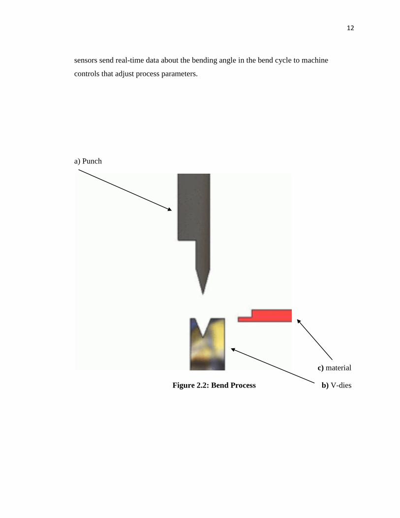
12
sensors send real-time data about the bending angle in the bend cycle to machine
controls that adjust process parameters.
a) Punch
c) material
Figure 2.2: Bend Process b) V-dies

13
2.4 Types of dies
Table 2.4 shows several types of die that have in industry and figure 2.5 shows
typical types of V-dies.
(Table 2.4: Types of die)
Types of die Description
V-dies most common type of die. The bottom dies can be
made with different-sized die openings to handle a
variety of materials and bend angles.
Rotary bending dies a cylindrical shape with an 88-degree V-notch cut
along its axis is seated in the "saddle" of the
punch.The die is an anvil over which the rocker
bends the sheet.
90degree dies largely used for bottoming operations. The die
opening dimension depends on material thickness.
Acute angle (air-bending)
dies
used in air bending, these can actually be used to
produce acute, 90 degree, and obtuse angles by
varying how deeply the punch enters the die by
adjusting the ram.
Gooseneck (return-flanging)
dies
The punch is designed to allow for clearance of
already formed flanges
Offset dies a combination punch and die set that bends two
angles in one stroke to produce a Z shape.
Hemming dies two-stage dies combining an acute angle die with a
flattening tool.
Seaming dies There are a number of ways to build dies to produce
seams in sheets and tubes.
Radius dies radiused bend can be produced by a rounded punch.

14
The bottom die may be a V-die or may include a
spring pad or rubber pad to form the bottom of the
die.
Beading dies A bead or a "stopped rib" may be a feature that
stiffens the resulting part. The punch has a rounded
head with flat shoulders on each side of the bead.
The bottom die is the inverse of the punch.
Curling dies The die forms a curled or coiled edge on the sheet.
Tube- and pipe-forming dies a first operation bends the edges of the sheet to make
the piece roll up. Then a die similar to a curling die
causes the tube to be formed. Larger tubes are
formed over a mandrel.
Four-way die blocks A single die block may have a V machined into each
of four sides for ease of changeover of small jobs.
U-bend dies with a rounded bottom. Springback may be a
problem and a means may need to be provided for
countering it.
Channel-forming dies A punch can be pressed into a die to form two angles
at the bottom of the sheet, forming an angular
channel.
Box-forming dies While a box may be formed by simple angle bends
on each side, the different side lengths of a
rectangular box must be accommodated by building
the punch in sections. The punch also needs to be
high enough to accommodate the height of the
resulting box's sides.
Corrugating dies Such dies have a wavy surface and may involve
spring-loaded punch elements.
15
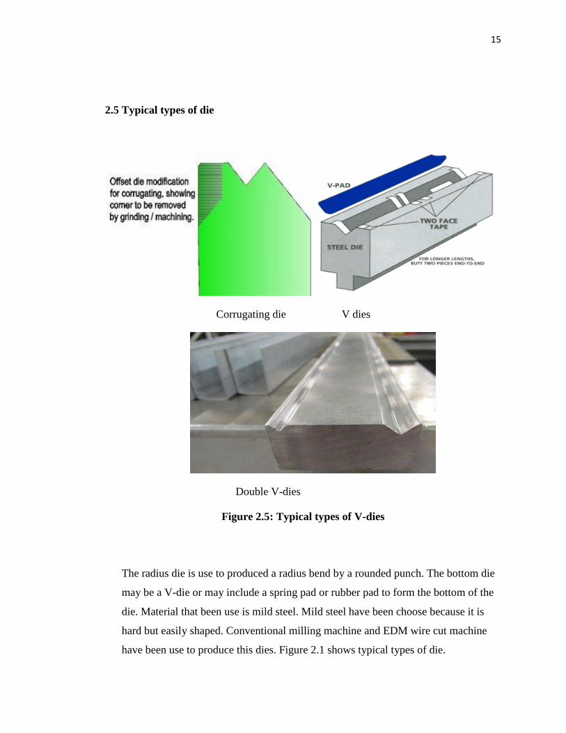
2.5 Typical types of die
Corrugating die V dies
Double V-dies
Figure 2.5: Typical types of V-dies
The radius die is use to produced a radius bend by a rounded punch. The bottom die
may be a V-die or may include a spring pad or rubber pad to form the bottom of the
die. Material that been use is mild steel. Mild steel have been choose because it is
hard but easily shaped. Conventional milling machine and EDM wire cut machine
have been use to produce this dies. Figure 2.1 shows typical types of die.

16
CHAPTER 3
METHODOLOGY
3.1 Introduction
The project starts with literature review and research about the title. This is
consist a review of the current design and gather the other information about the current
design. These tasks have been done through research on the internet, books and others
sources.
After gathering all the relevant information, the project undergoes design in
Solid Work. In this step, from the information gather from the review is use to make a
design The design is transfer to solid modelling and engineering drawing using
SolidWorks program.
3.2 Design Process
In using Solid Work software, there are many function of each icon to draw the
design of the die (refer figure 3.2). Each icon have it function to draw every part of the

17
drawing. For figure 3.1 and figure 3.2, only the icon like in the table 3.1 are use to make
every part of the drawing. (Detail drawing and dimension as attached in Appendix A.)
Table 3.1: Icon in solidwork to draw and design the round die
Figure 3.1: Front view of round die Figure 3.2 : Side view of round die
No Icon Function
1 To make fillet
2 To make chamfer
3 To draw circle
4 To draw rectangle
5 To extruded cut
6 To extruded
7 To draw line

18
3.3 Fabrication Process
After all the drawing finished, the drawing was used as a reference for the next
process which is fabrication process. This process is consists fabricate the parts that have
design before by following all the dimension using various type of manufacturing
process. The manufacturing process included in the process is cutting, facing, boring and
the others. During the fabrication process, if there is something wrong occur such as not
balance dimension so the process stop and go back to previous step, check the design
back.
During the fabrication process are need to use a certain machine like
conventional milling machine (figure 3.3), edm wire cut machine (figure 3.4) and other.
There are the certain basic in using that machine, like milling machine. The x-axis, y-
axis, and z-axis. In the facing process after the work piece are clamped, just need to
move the „mata alat‟ to x-axis or y-axis or z-axis.
After that is the testing process. In this process is just test the project can be use
and same with the current function. Due to some problem that will discuss later in other
chapter, the testing only can be made on several aspect only. During the testing, if
problem occur such as malfunction, the process step back to previous process, which is
fabrication.
.

19
Figure 3.3: Conventional Milling Machine
Figure 3.4: EDM Wirecut Machine

20
CHAPTER 4
RESULTS AND DISCUSSION
4.1 Introduction
After designing in SolidWork software is a fabrication process. These processes is
about using the material Selection and make the product base on the design and by
followed the design dimension. Many process will be use in this fabrication process, like
cutting, facing, boring and other. Fabrication process is difference from manufacturing
process in term of production quantity. Fabrication process is a process to make only one
product rather then manufacturing process that focus to large scale production. In the
project fabrication process needed to make the round dies, fabrication process was used
at the whole system production. This was include by part fabrication until assembly to
others component.

21
4.2 Processes
In fabricating process, several process have been used to fabricate the round dies,
which is;
-using the conversional milling machine
Cutting unwanted materials as roughing process
Facing is to face critical dimension area
-using the edm wirecut machine to cut complex shape in the drawing
This complex shape to make the upper part of round die
Figure 4.1: Face mill

22
4.3 Step by step of the Process
The fabrication process is start with measuring and marking the raw material into
the dimension needed. Then when done the marking process, cut the materials using
bend saw. All the measuring and marking process is done by using steel ruler, measuring
tape, steel marker and vernier calliper.
After cutting process is done, the material goes to next process, fabricate. First
part is a base. By using conversional milling machine, the first step is clamp the work
piece and start with facing process. The facing process is using by face mill and the
dimension is follow on drawing. When the facing process is done, the next process is
cutting. In this process is need to use an edge finder and end mill. The dimension of this
work piece is 120mm x 30mm. and the thickness is 50mm.
The part that should be cut by the end mill is the 20mm base by using
conversional milling machine. The original length is 30 mm so I have to reduce it to
13mm according to the drawing. Make a slot with dimension 8.5mm each.
After done doing that, arrange back the tool that have been use to the original
position. Make sure the machine have been clean neatly and being off before go out.
The next step is the process for making the round die using edm wire cut. Firstly
convert the drawing into dxf format. The edm wirecut only can read dxf format which is
mastercam format. Then save the drawing in the disket to key in it to the machine. Then
the machine will read the drawing and the coding will appear on its own. Then setting
the workpiece into the machine, clamp the workpiece tide and neatly. Then with the help

23
of the engineer assistant, run the program and the machine will cut the workpiece just
same as the drawing that have been key in the machine.(refer figure 4.2 and figure 4.3)
Figure 4.2: EDM wirecut cutting process 1
Figure 4.3: EDM wirecut cutting process 2
24
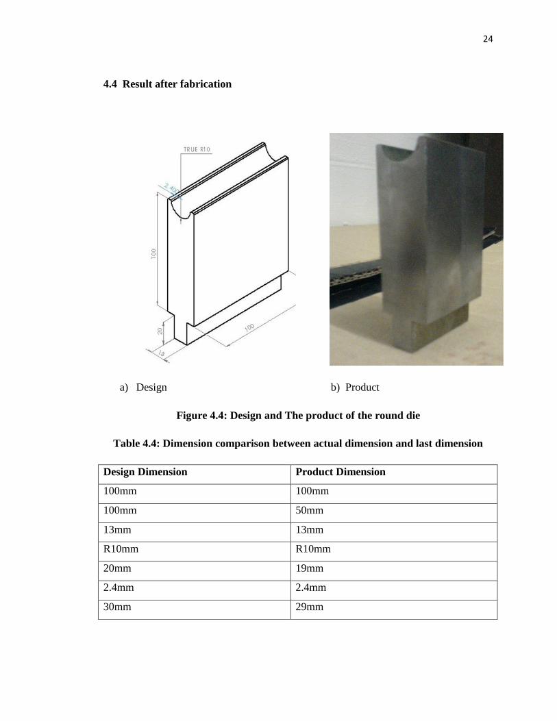
4.4 Result after fabrication
a) Design b) Product
Figure 4.4: Design and The product of the round die
Table 4.4: Dimension comparison between actual dimension and last dimension
Design Dimension Product Dimension
100mm 100mm
100mm 50mm
13mm 13mm
R10mm R10mm
20mm 19mm
2.4mm 2.4mm
30mm 29mm