Nanoparticle-Doped Polydimethylsiloxane Fluid Enhances the ...
i
DEVELOPMENT OF POLYSULFONE-
POLYDIMETHYLSILOXANE (PSf-PDMS) THIN FILM
COMPOSITE (TFC) MEMBRANE FOR CO2/ N2 GAS SEPARATION
NUR ATIKAH BINTI CHE EMBEE
A thesis submitted to the Faculty of Chemical and Natural Resources Engineering in
partial fulfillment of the requirement for the Degree of Bachelor of Engineering in
Chemical Engineering (Gas Technology)
Faculty of Chemical and Natural Resources Engineering
Universiti Malaysia Pahang
FEBRUARY 2013
vi
DEVELOPMENT OF POLYSULFONE-POLYDIMETHYLSILOXANE
(PSf-PDMS) THIN FILM COMPOSITE (TFC) MEMBRANE FOR
CO2/ N2 GAS SEPARATION
ABSTRACT
The capture and storage of carbon dioxide has been identified as one potential
solution to greenhouse gas driven climate change. Efficient separation technologies
are required for removal of carbon dioxide from flue gas streams to allow this
solution to be widely implemented. This study is mainly focusing on the effect of
different concentration of PDMS in dip-coating solution on the membrane’s
performance. The asymmetric thin flat sheet membrane was prepared by dry/ wet
phase inversion process consisting 20 wt% of polysulfone (PSf) as the support layer
polymer and 80 wt% of N-methyl-2-pyrrolidone (NMP) as the solvent. PDMS was
coated on the support PSf membrane with the composition of 10, 15 and 20 wt% of
PSf in n-hexane respectively. The characterization of morphology of TFC membrane
will be conducted by using Scanning Electron Microscopy (SEM) and Fourier
Transform Infrared Radiation (FTIR). The membrane’s performance and the
selectivity of CO2/N2 separation will be determined by conducting gas permeation
test. The result obtained, show that membrane with highest concentration of PDMS
in dip-coating solution give a highest performance in selectivity and unfortunately it
contribute to lower permeability. It is vice versa from the membrane without PDMS
in the top layer which gives highest value of permeability but lowest in selectivity.
From the characterization and permeation test of the membrane, hereby the
membrane with highest percentage of PDMS should be selected for the future
development of membrane due to its highest value of selectivity which contributes to
highest efficiency in separating the gas.

vii
PENGHASILAN POLISULFON-POLIDIMETILSILOKSAN
(PSf-PDMS) KOMPOSIT FILEM NIPIS (TFC) MEMBRAN UNTUK
PENGASINGAN GAS CO2/ N2
ABSTRAK
Penangkapan dan penyimpanan karbon dioksida telah dikenal pasti berpotensi
untuk penyelesaian gas rumah hijau yang didorong oleh perubahan iklim. Teknologi
pemisahan yang cekap diperlukan untuk penyingkiran karbon dioksida daripada
serombong aliran gas untuk membolehkan penyelesaian ini dapat dilaksanakan
secara meluas. Kajian ini memberi tumpuan kepada kesan kepelbagaian kepekatan
PDMS dalam larutan lapisan atas pada prestasi membran. Simetri nipis lembaran rata
membran telah disediakan melalui proses fasa balikan kering/ basah yang terdiri
20 wt% polysulfon (PSf) sebagai polimer lapisan sokongan dan 80 wt% N-methyl-2-
pyrrolidone (NMP) sebagai pelarut. PDMS telah disalut pada setiap membran
sokongan dengan komposisi 10, 15 dan 20 % dalam n-heksana. Pencirian morfologi
membran TFC akan dijalankan dengan menggunakan Imbasan Electron Microscopy
(SEM) dan Sinaran Inframerah Transformasi Fourier (FTIR). Prestasi membran iaitu
kepilihan pemisahan gas CO2/N2 akan ditentukan dengan menjalankan ujian
penyerapan gas. Berdasarkan keputusan yang diperolehi, ia menunjukkan bahawa
membran dengan kepekatan tertinggi PDMS dalam larutan lapisan atas memberikan
prestasi tertinggi dalam selektiviti dan malangnya ia menyumbang kepada
kebolehtelapan yang rendah. Ia adalah sebaliknya dari membran tanpa PDMS di
lapisan atas yang memberikan nilai tertinggi kebolehtelapan tetapi terendah pada
nilai selektiviti. Dari ujian pencirian dan penyerapan membran, dengan ini membran
dengan peratusan tertinggi PDMS perlu dipilih untuk penyediaan membran pada
masa hadapan kerana nilai tertinggi selektiviti yang menyumbang kepada kecekapan
tertinggi dalam mengasingkan gas.
viii
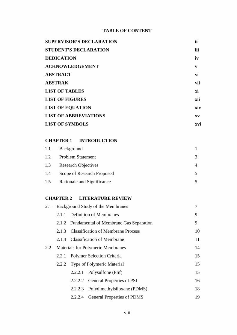
TABLE OF CONTENT
SUPERVISOR’S DECLARATION ii
STUDENT’S DECLARATION iii
DEDICATION iv
ACKNOWLEDGEMENT v
ABSTRACT vi
ABSTRAK vii
LIST OF TABLES xi
LIST OF FIGURES xii
LIST OF EQUATION xiv
LIST OF ABBREVIATIONS xv
LIST OF SYMBOLS xvi
CHAPTER 1 INTRODUCTION
1.1 Background 1
1.2 Problem Statement 3
1.3 Research Objectives 4
1.4 Scope of Research Proposed 5
1.5 Rationale and Significance 5
CHAPTER 2 LITERATURE REVIEW
2.1 Background Study of the Membranes 7
2.1.1 Definition of Membranes 9
2.1.2 Fundamental of Membrane Gas Separation 9
2.1.3 Classification of Membrane Process 10
2.1.4 Classification of Membrane 11
2.2 Materials for Polymeric Membranes 14
2.2.1 Polymer Selection Criteria 15
2.2.2 Type of Polymeric Material 15
2.2.2.1 Polysulfone (PSf) 15
2.2.2.2 General Properties of PSf 16
2.2.2.3 Polydimethylsiloxane (PDMS) 18
2.2.2.4 General Properties of PDMS 19

ix
2.3 Manufacturing Process 19
2.3.1 Dry Process 20
2.3.2 Wet Process 20
2.3.3 Dry/ Wet Process 21
2.4 Membrane Separation Technology 22
2.4.1 Types of Membranes 22
2.4.1.1 Porous Membranes 23
2.4.1.2 Non-Porous Membranes 24
2.4.2 Application of Membranes 26
2.4.2.1 Gas Separation 26
2.4.2.2 Carbon Capture 29
2.4.3 Advantages and Disadvantages of the Membranes 30
2.5 Membrane Processes and Separation Mechanisms 33
CHAPTER 3 METHODOLOGY
3.1 Research Design 35
3.2 Material Selection 37
3.2.1 Polymer Selection 37
3.2.1.1 Polysulfone (PSf) 37
3.2.2 Solvent Selection 38
3.2.2.1 N-Methyl-2-Pyrrolidone (NMP) 38
3.2.3 Coagulation Medium 38
3.2.3.1 Water (H2O) 38
3.2.4 Coating Solution 39
3.2.4.1 Polydimethylsiloxane (PDMS) 39
3.2.4.2 n-Hexane 39
3.3 Dope Solution Preparation 39
3.4 Asymmetric Flat Sheet Membrane Film Formation 42
3.5 Composite Membrane Preparation 42
3.6 Gas Permeation Test 43
3.7 Membrane Characterization 46
3.7.1 Scanning Electron Microscopy (SEM) 46
3.7.2 Fourier Transform Infrared Radiation (FTIR) 47
x
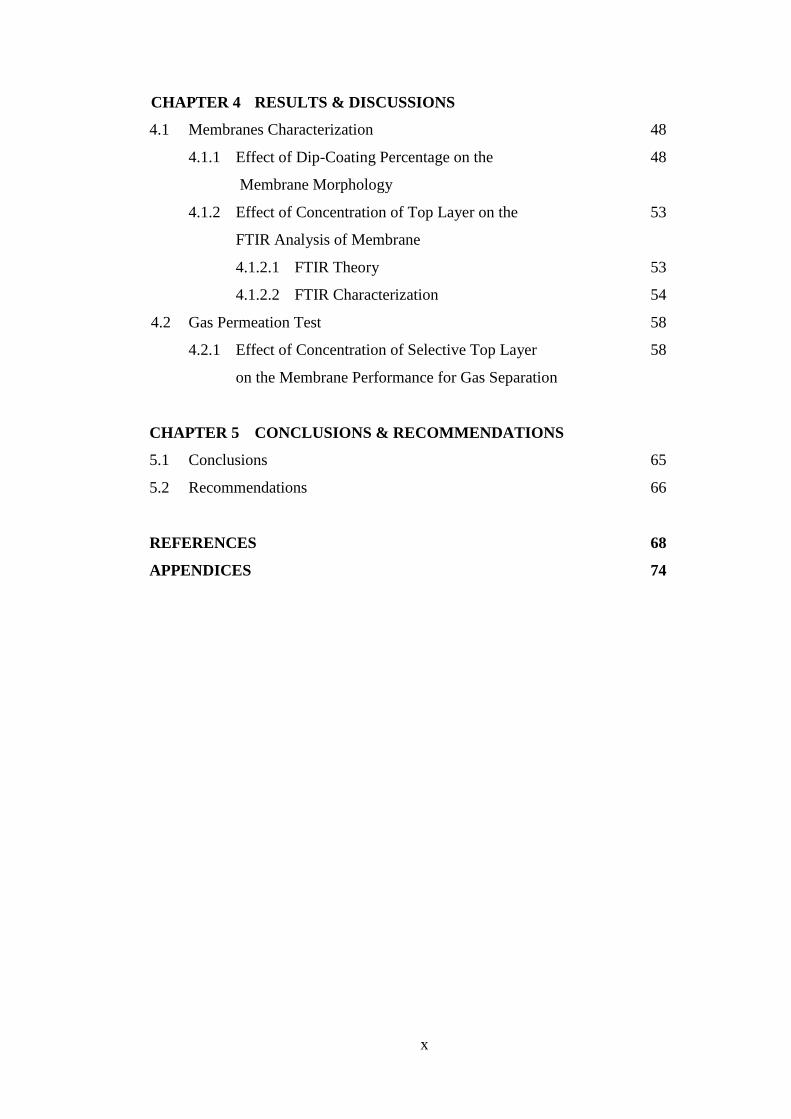
CHAPTER 4 RESULTS & DISCUSSIONS
4.1 Membranes Characterization 48
4.1.1 Effect of Dip-Coating Percentage on the 48
Membrane Morphology
4.1.2 Effect of Concentration of Top Layer on the 53
FTIR Analysis of Membrane
4.1.2.1 FTIR Theory 53
4.1.2.2 FTIR Characterization 54
4.2 Gas Permeation Test 58
4.2.1 Effect of Concentration of Selective Top Layer 58
on the Membrane Performance for Gas Separation
CHAPTER 5 CONCLUSIONS & RECOMMENDATIONS
5.1 Conclusions 65
5.2 Recommendations 66
REFERENCES 68
APPENDICES 74
xi
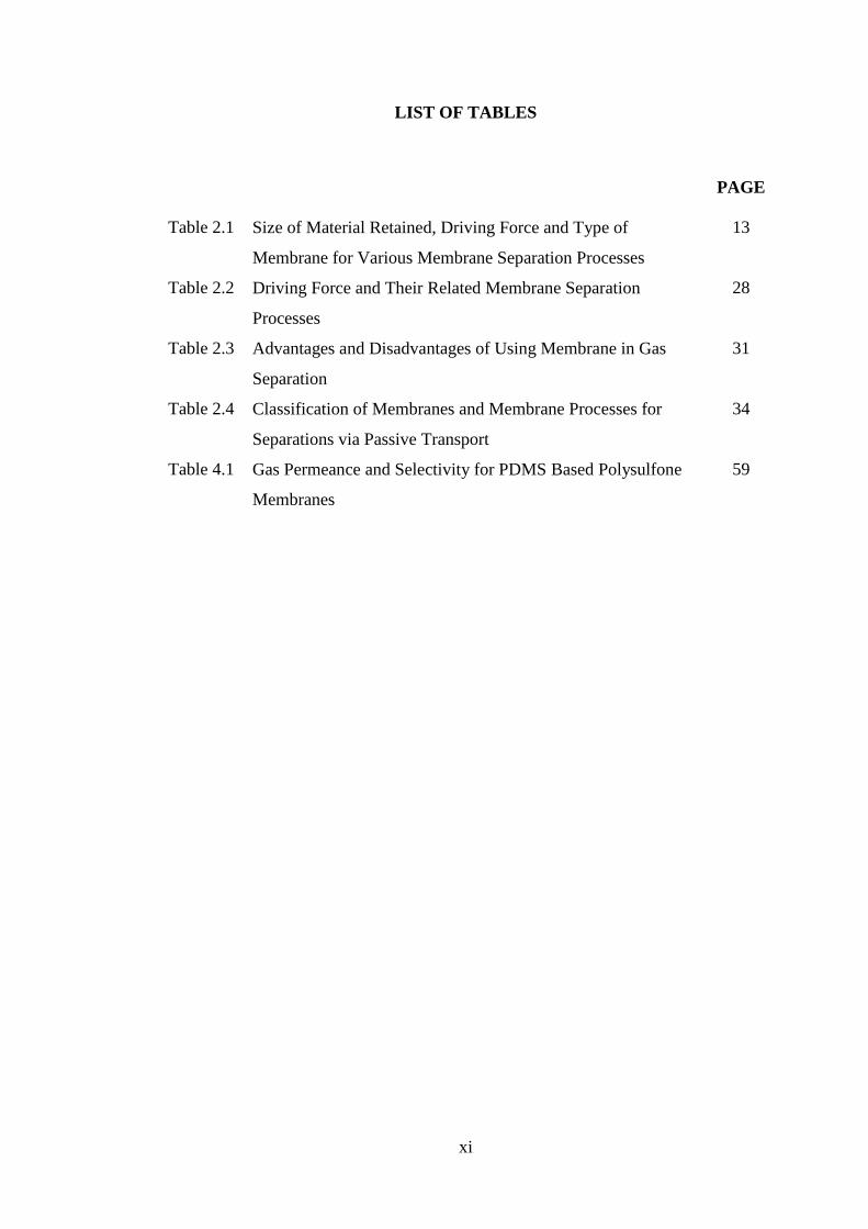
LIST OF TABLES
PAGE
Table 2.1 Size of Material Retained, Driving Force and Type of
Membrane for Various Membrane Separation Processes
13
Table 2.2 Driving Force and Their Related Membrane Separation
Processes
28
Table 2.3 Advantages and Disadvantages of Using Membrane in Gas
Separation
31
Table 2.4 Classification of Membranes and Membrane Processes for
Separations via Passive Transport
34
Table 4.1 Gas Permeance and Selectivity for PDMS Based Polysulfone
Membranes
59
xii
LIST OF FIGURES
Figure 2.1 A Schematic Representation of a Simple Membrane Process 8
Figure 2.2 Dead-end and Cross-flow Filtration Process 11
Figure 2.3 Pore Diameter Based on Different Type of Membrane
Process
12
Figure 2.4 Molecular Structure of PSf 17
Figure 2.5 Molecular Structure of PDMS 19
Figure 2.6 Schematic Diagram of Dry, Wet and Dry/ Wet Process 22
Figure 2.7 Membrane Classifications 25
Figure 2.8 Basic Principle of Membrane Separation 26
Figure 2.9 Relevant Parameters of a Single-Stage Membrane Process. 28
Figure 3.1 Research Design Flow Chart 36
Figure 3.2 Dope Solution Preparation Set Up 41
Figure 3.3 Gas Permeation Test Apparatus 44
Figure 3.4 A Cross-Sectional View of Assembled Permeation cell and
Gas Flow Direction
44
Figure 4.1 SEM images of PSf pure membrane and PDMS/ PSf
composite membrane
51
Figure 4.2 Schematic of FTIR during Operation 54
Figure 4.3 FTIR Absorbance Peak for 0% PDMS of PDMS–PSf
Membrane
56
Figure 4.4 FTIR Absorbance Peak for 10% PDMS of PDMS-PSf
Membrane
56
Figure 4.5 FTIR Absorbance Peak for 15% PDMS of PDMS–PSf
Membrane
57
Figure 4.6 FTIR Absorbance Peak for 20% PDMS of PDMS–PSf
Membrane
57
Figure 4.7 Graph of CO2/ N2 Selectivity against Feed Pressure 63
Figure 4.8 Graph of CO2 Permeability against Feed Pressure 63
Figure 4.9 Graph of N2 Permeability against Feed Pressure 64
Figure A.1 Dope Solution Preparation 74
Figure A.2 Membrane Casting Process 74
Figure A.3 Dip-Coating Process 75

xiii
Figure A.4 Scanning Electron Microscopy (SEM) 75
Figure A.5 Fourier Transform Infrared Radiation (FTIR) 76
Figure A.6 Gas Permeation Test 76
xiv
LIST OF EQUATION
PAGE
Equation 3.1 Permeation rate 45
Equation 3.2 Permeance 45
Equation 3.3 Conversion to GPU 45
Equation 3.4 Selectivity 46
xv
LIST OF ABBREVIATIONS
CH4 - Methane gas
CO2 - Carbon dioxide
FTIR - Fourier Transform Infrared Radiation
H2O -Water
HMWC - High Molecular Weight Component
LMWC - Low Molecular Weight Component
MF - Microfiltration
N2 - Nitrogen
NF - Nanofiltration
NMP - N-Methyl-2-Pyrrolidone
PDMS - Polydimethylsiloxane
PSf - Polysulfone
RO - Reverse Osmosis
SEM - Scanning Electron Microscopy
TFC - Thin Film Composite
UF -Ultrafiltration

xvi
LIST OF SYMBOLS
°C - Degree Celcius
min - minute
% - Percentage
ppm - Part per million
mm - milimeter
1
CHAPTER 1
INTRODUCTION
This chapter will give the ideas about the significant of the research formulation.
The first chapter will cover up the subtopic of background of study or information,
problem statement, research objectives, scope of proposed research, expected outcomes
and significant of the proposed research.
1.1 Background
Enhancements of the greenhouse effect in the worldwide have contributed to the
study that can recover this problem. The most abundant greenhouse gas CO2 has risen
from preindustrial levels of 280 parts per million (ppm) to present levels of over 365
ppm (Dantas et al, 2011). Carbon dioxide, CO2 arise from different emission sources,
particularly flue gas from power stations, steel works and chemical industries.
According to the study done by Mitsubishi Heavy Industries, Ltd., 98% of CO2
emissions are derived from fossil fuel combustion, exhausted to atmosphere by flue gas
2
stacks from furnace boilers, gas turbines and engine emission. The content of the flue
gases that released at atmospheric pressure usually containing Oxygen, Carbon Dioxide,
Nitrogen, NOx, SOx and dust particulate impurities. Referring to Halmann research, the
actual warming of the earth due to the atmospheric blanket is strongly influenced by
small amounts of gases in the earth’s atmosphere, particularly CO2 and water vapors.
These gases trap the heat due to their molecular structures, which absorb mainly
reflected solar radiation from the earth’s surface. H2O vapor absorbs solar radiation in
the range 4 to 7 microns while CO2 absorbs radiation in the range of 13 to 19 microns.
Because of their behavior, hence they are called greenhouse gases.
A large number of polymeric membranes have been developed for a variety of
industrial applications. Each application imposes specific requirement on the membrane
material and pore structure.
The separation process in the membrane involves three phases, which is two
gases (vapor) phases, two liquid phases and a vapor and liquid phases. In the membrane
process, the feed mixture can be separated into two types. Firstly, retentate which means
the part of the feed that does not pass through the membrane. Secondly, permeate which
means the part of the feed that passes through the membrane.
3
1.2 Problem Statement
Anthropogenic climate change is rapidly becoming one of the major issues in
environmental science. Global temperatures are projected to raise between 1.4 and 5.8
oC by 2100 in the absence of climate change policies (Houghton, 2001). This increase in
global temperature is likely to cause a number of negative effects; including rising sea
level, changes in ecosystem, loss of biodiversity and reduction in crop yields (McCarthy
et al., 2001). One of the major factor contribute to the global warming is an emission of
flue gas from power plant. The main components of the flue gas are CO2, N2, O2 and
H2O, air pollutant such as SOx, NOx, particulates, as well as other contaminants. CO2 is
an undesirable gas that contributes to the corrosion and other operational problems. The
treatment of flue gas to enable the capture and storage of relatively pure CO2 involves
identifying the impurities in the flue gas that may affect the transport and storage of
CO2.
Membrane technology is considered as a feasible option, but the membranes
currently available for industrial gas separations have not been applied for commercial
flue gas applications. To be economically viable, the membrane should exhibit a high
permeability and a high selectivity for the components to be separated. Normally,
conventional membranes are good only for bulk separations, and they are often
combined with other gas separation techniques when the acid gases are present at low
concentrations (Francisco et al., 2007).

4
It may be mentioned that facilitated transport for CO2 separation has been
studied using immobilized liquid membranes where the carrier solution is confined in
the pores of a membrane matrix. However, this matrix membrane suffers from problems
associated with solvent loss and washout. Moreover, other technologies in gas separation
systems such as chromatography or distillation in which required high energy
requirement.
1.3 Research Objectives
The main objective of this research is to develop PSf-PDMS-TFC membrane for
CO2/N2 gas separation. The developed membrane should have considerably high CO2
permeability in conjunction with high CO2/N2 selectivity, can withstand high trans-
membrane pressure differentials and have long term stability.
Specific objectives are:
i. To synthesis thin film composite membrane by using PSf and PDMS.
ii. To test the membrane performance in CO2/N2 gas separation.
iii. To characterize TFC membrane by using Scanning Electron Microscopy (SEM)
and Fourier Transform Infrared Spectroscopy (FTIR).
5
1.4 Scope of Research Proposed
The main scopes of research are:
i. Conduct dry/ wet phase inversion process in developing membrane.
ii. Conduct permeation test to examine the performance of membrane by study the
effect of different percentage of PDMS used in dip-coating solution.
iii. Characterization of the membrane is conducted by using Scanning Electron
Microscopy (SEM) and Fourier Transform Infrared Radiation (FTIR) with help
of the physical and chemical properties of membrane.
1.5 Rationale and Significance
The rationale and significance implement membrane as a medium in gas
separation are it capable to increase process performance, save energy, reduce costs and
minimize the environment impact. Membrane operations are in principle the most
attractive candidates to satisfy the process intensification concepts and requirements.
Their intrinsic characteristic of efficiency and operational simplicity, high
selectivity and permeability for the transport of specific components, compatibility
between different membrane operations in integrated systems, low energetic
requirement, good stability under operating conditions and environment compatibility,
6
easy control and scale up, and large operational flexibility represent the membrane is the
most rational and significance in industrial productions (Drioli and Romano, 2001).

7
CHAPTER 2
LITERATURE REVIEW
2.1 Background Study of the Membranes
Membranes offer the greatest potential in the gas separation process. Membrane
applications in the gas separation are available for bulk removal of carbon dioxide, CO2,
removal and separation of nitrogen, N2 from natural gas and separation of natural gas
liquid from methane, CH4. The separation of gas by thin barrier termed as membranes is
a dynamic and rapidly growing field, and it has been proven to be technically and
economically superior to other emerging technology.
Figure 2.1 illustrate simplified and generalized schematic diagram of the
membrane in separation process.

8
Figure 2.1 A Schematic Representation of a Simple Membrane Process (Farid, 2010).
The barrier which is called as a membrane is a medium to separate two bulks of
phases. The membrane controls the passage of different chemical substances through it
which depend upon the nature of the chemical substances and the membrane (Scott,
1995).
Membrane technology has been widely used in the industry for many years for
separating liquids and liquid-solid mixtures before it being applied to gas separation. In
order to obtain more profitable method in gas separation process, membrane systems
was then gradually introduced for gas separating systems (Dhingra, 1997). Concomitant
with developments in the field of synthetic polymeric materials, this new technology is
successfully addressed.
As stated by Abedini & Nezhadmoghadam in their research, the progress in
membrane science and technology was accelerated during the 1980s by the development
and refinement of synthetic polymeric membranes. During 1980s, membrane gas

9
separation emerged on a large scale as a commercial process. During this period,
significant progress was made in virtually every aspect of membrane technology,
including improvements in membrane formation process, chemical and physical
structures, configuration and applications.
2.1.1 Definition of Membranes
As mentioned by Mulder (1996), membrane can be defined as a selective barrier
between two phases, the “selective” being inherent to a membrane process. In addition
membrane is an inter-phase between the two bulk phases. It is either a homogenous
phase or a heterogeneous collection of phases (Sakai, 1994).
In the concept of the membrane science, a synthetic membrane behaves as a thin
barrier between two phases through which differential transport can occur. Driving
forces that facilitate this transport are pressure, concentration, and electrical potential
across the medium (Koros, Ma, Shimidzy, 1996). The transportation process is a non-
equilibrium process and the difference in transport rates through the membrane will
make the chemical species is separated.
2.1.2 Fundamental of Membrane Gas Separation
In the process of selecting the proper polymer for the preparation a membrane in
which capable of removing organic solvents efficiently from air, a brief discussion of the
basics of the mass transport through membranes is very helpful.

10
The permeation of a gaseous component through a homogenous membrane can
to a first approximation be described by the solution diffusion membrane model and is
determined mainly by three parameters: (1) The permeability, (2) the concentration of
the components in the membrane phase and (3) the driving force or driving force acting
on this component (Strathman, Bell and Kimmerle, 1986).
2.1.3 Classification of Membrane Process
In filtration process by using membrane, there are two main classifications that
been highlighted which are Dead-end and Cross-flow filtration. In Dead-end (or in line
filtration), with under pressure condition, the entire fluid flow is forced through the
membrane and any solid or colloidal particles accumulate on the membrane surface or in
its interior to form a cake. The membrane pores can be blocked by accumulation of
solids on the surface. The pressure should be implemented on the membrane in order to
maintain the required flow increase until a washing cycle is performed or the membrane
must be replaced. Membrane fouling due to accumulation of suspended or dissolved
substances on external surface within the pore structure can result severe reduction in
permeability (Mhurchu and Foley, 2006).
Meanwhile in cross-flow system, the fluid on the downstream side of the
membrane moves away from the membrane. this flow is circulated across the membrane
surface producing two streams, a clean permeate stream and concentrated retentate
stream. A shear force created on the surface of the membrane due to feed flow is
circulated over the membrane will reduces blocking of membrane pores on the surface
11
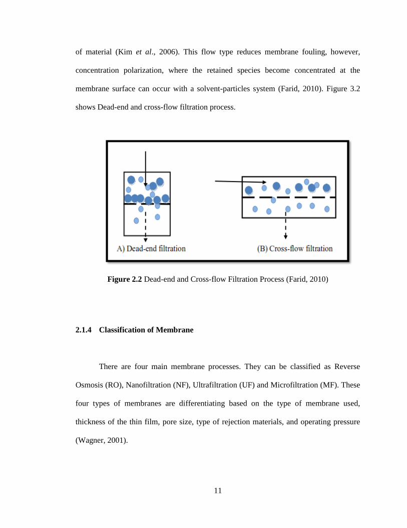
of material (Kim et al., 2006). This flow type reduces membrane fouling, however,
concentration polarization, where the retained species become concentrated at the
membrane surface can occur with a solvent-particles system (Farid, 2010). Figure 3.2
shows Dead-end and cross-flow filtration process.
Figure 2.2 Dead-end and Cross-flow Filtration Process (Farid, 2010)
2.1.4 Classification of Membrane
There are four main membrane processes. They can be classified as Reverse
Osmosis (RO), Nanofiltration (NF), Ultrafiltration (UF) and Microfiltration (MF). These
four types of membranes are differentiating based on the type of membrane used,
thickness of the thin film, pore size, type of rejection materials, and operating pressure
(Wagner, 2001).

12
Figure 2.3 Pore Diameter Based on Different Type of Membrane Process (Hu, 2001)
Reverse Osmosis (RO) is the tightest possible membrane process in liquid/liquid
separation. Water is in principle the only material passing through the membrane;
essentially all dissolved and suspended material is rejected. In RO process, a membrane
which impedes the passage of a low molecular weight solute is placed between a solute-
solvent solution and a pure solvent. The solvent is diffuses into the solution by osmosis.
In RO, a reverse pressure difference is imposed which causes the flow of solvent to
reverse, as in the desalination of seawater (Wagner, 2001, Geankoplis, 2003).
Nanofiltration (NF) rejects only ion with more than one negative charge, such as
sulfate or phosphate, while passing single charged ion. NF also rejects uncharged,
dissolved materials and positively charged ions according to the size and shape of the
molecule in question. Rejection of sodium chloride with NF varies from 0-50 percent
depending on the feed concentration (Wagner, 2001).