DEVELOPMENT OF NANOCRYSTALLINE IRON-CHROMIUM ALLOY … · DEVELOPMENT OF NANOCRYSTALLINE...
48
DEVELOPMENT OF NANOCRYSTALLINE IRON-CHROMIUM ALLOY BY MEANS OF SINTERING AND ION IMPLANTATION FOR INTERCONNECT APPLICATION IN HIGH-TEMPERATURE SOLID OXIDE FUEL CELLS DENI SHIDQI KHAERUDINI A thesis is submitted in fulfilment of the requirements for the award of the Degree of Master in Mechanical Engineering Faculty of Mechanical and Manufacturing Engineering Universiti Tun Hussein Onn Malaysia NOVEMBER 2011
Transcript of DEVELOPMENT OF NANOCRYSTALLINE IRON-CHROMIUM ALLOY … · DEVELOPMENT OF NANOCRYSTALLINE...
DEVELOPMENT OF NANOCRYSTALLINE IRON-CHROMIUM ALLOY BY
MEANS OF SINTERING AND ION IMPLANTATION FOR INTERCONNECT
APPLICATION IN HIGH-TEMPERATURE SOLID OXIDE FUEL CELLS
DENI SHIDQI KHAERUDINI
A thesis is submitted in
fulfilment of the requirements for the award of the
Degree of Master in Mechanical Engineering
Faculty of Mechanical and Manufacturing Engineering
Universiti Tun Hussein Onn Malaysia
NOVEMBER 2011
v
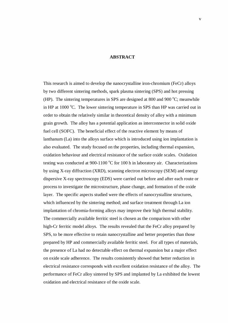
ABSTRACT This research is aimed to develop the nanocrystalline iron-chromium (FeCr) alloys
by two different sintering methods, spark plasma sintering (SPS) and hot pressing
(HP). The sintering temperatures in SPS are designed at 800 and 900 oC; meanwhile
in HP at 1000 oC. The lower sintering temperature in SPS than HP was carried out in
order to obtain the relatively similar in theoretical density of alloy with a minimum
grain growth. The alloy has a potential application as interconnector in solid oxide
fuel cell (SOFC). The beneficial effect of the reactive element by means of
lanthanum (La) into the alloys surface which is introduced using ion implantation is
also evaluated. The study focused on the properties, including thermal expansion,
oxidation behaviour and electrical resistance of the surface oxide scales. Oxidation
testing was conducted at 900-1100 oC for 100 h in laboratory air. Characterizations
by using X-ray diffraction (XRD), scanning electron microscopy (SEM) and energy
dispersive X-ray spectroscopy (EDS) were carried out before and after each route or
process to investigate the microstructure, phase change, and formation of the oxide
layer. The specific aspects studied were the effects of nanocrystalline structures,
which influenced by the sintering method; and surface treatment through La ion
implantation of chromia-forming alloys may improve their high thermal stability.
The commercially available ferritic steel is chosen as the comparison with other
high-Cr ferritic model alloys. The results revealed that the FeCr alloy prepared by
SPS, to be more effective to retain nanocrystalline and better properties than those
prepared by HP and commercially available ferritic steel. For all types of materials,
the presence of La had no detectable effect on thermal expansion but a major effect
on oxide scale adherence. The results consistently showed that better reduction in
electrical resistance corresponds with excellent oxidation resistance of the alloy. The
performance of FeCr alloy sintered by SPS and implanted by La exhibited the lowest
oxidation and electrical resistance of the oxide scale.
vi
ABSTRAK
Penyelidikan ini bertujuan untuk membangunkan besi-kromium (FeCr) aloi
nanocrystalline dengan dua kaedah pensinteran yang berbeza, spark plasma sintering
(SPS) dan hot pressing (HP). Suhu pensinteran di SPS ditetapkan pada 800 dan 900 oC; sementara itu, di HP adalah pada 1000 oC. Suhu pensinteran yang lebih rendah di
SPS daripada HP telah digunakan dalam usaha untuk mendapatkan ketumpatan teori
aloi yang hampir sama dengan pertumbuhan butiran yang minimum. Ianya
mempunyai potensi aplikasi sebagai interconnector dalam sel bahan bakar oksida
padu (SOFC). Kebaikan penggunaan unsur reaktif iaitu lanthanum (La) ke
permukaan aloi yang diperkenalkan menggunakan kaedah implantasi ion juga dikaji.
Kajian ini tertumpu kepada sifat bahan iaitu pengembangan haba, pengoksidaan dan
penebatan elektrik pada lapisan permukaan oksida. Pengoksidaan ujian dilakukan
pada 900-1100 oC selama 100 jam di ruang udara makmal. Spesimen teroksida
ditentukan dengan menggunakan pembelauan sinar-X (XRD), mikroskop pengimbas
elektron (SEM) dan tenaga penyebaran sinar-X spektroskopi (EDS) yang dilakukan
sebelum dan selepas pada setiap proses untuk mengkaji mikrostruktur, perubahan
fasa, dan pembentukan lapisan oksida. Aspek spesifik yang diteliti adalah kesan
struktur nanocrystalline yang dipengaruhi oleh kaedah sintering; dan rawatan
permukaan melalui implantasi ion La dimana ianya dapat meningkatkan sifat
kestabilan haba yang tinggi. Keluli feritik komersial dipilih sebagai perbandingan
dengan model aloi Cr feritik. Hasil kajian menunjukkan bahawa FeCr aloi
menggunakan kaedah SPS lebih efektif dalam mengekalkan sifat nanocrystalline
berbanding dari yang dihasilkan oleh HP dan keluli feritik komersial. Untuk semua
jenis bahan, kehadiran La tidak memberi kesan pada pengembangan haba namun
memberi kesan yang besar pada pengikatan oksida. Keputusan yang konsisten
menunjukkan bahawa pengurangan rintangan elektrik selari dengan rintangan
pengoksidaan pada aloi. Prestasi FeCr aloi yang disinter oleh SPS dan diimplan oleh
La menunjukkan pengoksidaan dan rintangan elektrik yang terendah.
vii
CONTENTS
TITLE i
DECLARATION ii
DEDICATION iii
ACKNOWLEDGEMENTS iv
ABSTRACT v
ABSTRAK vi
CONTENTS vii
LIST OF TABLES xi
LIST OF FIGURES xii
LIST OF SYMBOLS AND ABBREVIATIONS xvi
LIST OF APPENDICES xviii
CHAPTER 1 INTRODUCTION 1
1.1 Background of Study 1
1.2 Problem Statement 5
viii
1.3 Objectives of Study 5
1.4 Scopes of Study 6
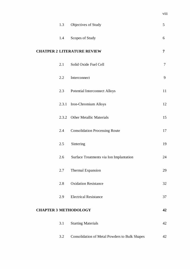
CHATPER 2 LITERATURE REVIEW 7
2.1 Solid Oxide Fuel Cell 7
2.2 Interconnect 9
2.3 Potential Interconnect Alloys 11
2.3.1 Iron-Chromium Alloys 12
2.3.2 Other Metallic Materials 15
2.4 Consolidation Processing Route 17
2.5 Sintering 19
2.6 Surface Treatments via Ion Implantation 24
2.7 Thermal Expansion 29
2.8 Oxidation Resistance 32
2.9 Electrical Resistance 37
CHAPTER 3 METHODOLOGY 42
3.1 Starting Materials 42
3.2 Consolidation of Metal Powders to Bulk Shapes 42
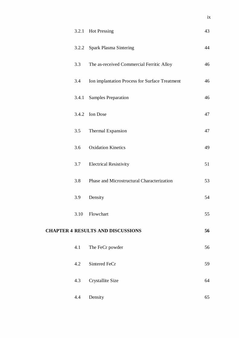
ix
3.2.1 Hot Pressing 43
3.2.2 Spark Plasma Sintering 44
3.3 The as-received Commercial Ferritic Alloy 46
3.4 Ion implantation Process for Surface Treatment 46
3.4.1 Samples Preparation 46
3.4.2 Ion Dose 47
3.5 Thermal Expansion 47
3.6 Oxidation Kinetics 49
3.7 Electrical Resistivity 51
3.8 Phase and Microstructural Characterization 53
3.9 Density 54
3.10 Flowchart 55
CHAPTER 4 RESULTS AND DISCUSSIONS 56
4.1 The FeCr powder 56
4.2 Sintered FeCr 59
4.3 Crystallite Size 64
4.4 Density 65
x
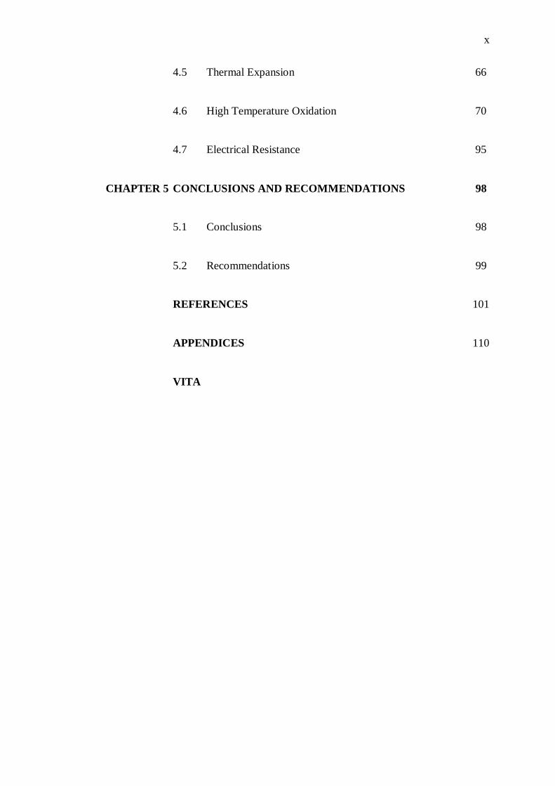
4.5 Thermal Expansion 66
4.6 High Temperature Oxidation 70
4.7 Electrical Resistance 95
CHAPTER 5 CONCLUSIONS AND RECOMMENDATIONS 98
5.1 Conclusions 98
5.2 Recommendations 99
REFERENCES 101
APPENDICES 110
VITA
xi
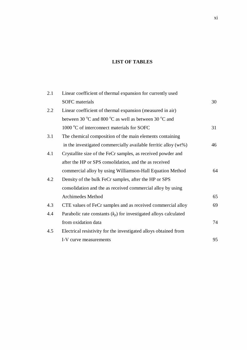
LIST OF TABLES
2.1 Linear coefficient of thermal expansion for currently used
SOFC materials 30
2.2 Linear coefficient of thermal expansion (measured in air)
between 30 oC and 800 oC as well as between 30 oC and
1000 oC of interconnect materials for SOFC 31
3.1 The chemical composition of the main elements containing
in the investigated commercially available ferritic alloy (wt%) 46
4.1 Crystallite size of the FeCr samples, as received powder and
after the HP or SPS consolidation, and the as received
commercial alloy by using Williamson-Hall Equation Method 64
4.2 Density of the bulk FeCr samples, after the HP or SPS
consolidation and the as received commercial alloy by using
Archimedes Method 65
4.3 CTE values of FeCr samples and as received commercial alloy 69
4.4 Parabolic rate constants (kp) for investigated alloys calculated
from oxidation data 74
4.5 Electrical resistivity for the investigated alloys obtained from
I-V curve measurements 95
xii
LIST OF FIGURES
2.1 Typical SOFC single cell configuration 8
2.2 Schematic of a typical planar SOFC stack 9
2.3 Phase diagram of Fe-Cr system 13
2.4 The three steps of sintering 17
2.5 Powder metallurgy route 19
2.6 Schematic of the hot pressing technique 20
2.7 Structural changes accompanying the preparation of a sintered product 20
2.8 Basic configuration of a typical SPS system 21
2.9 A schematic drawing of the pulsed current that flows through
powder particles 22
2.10 Comparison of the relative densities of the Ti specimen prepared by
SPS and conventional HP sintering as a function of the sintering
temperature 23
2.11 SEM fractured surface of the Ti specimen prepared (a) by SPS at 700 oC
for 5 min and (b) by conventional HP sintering at 900 oC for 1 h 23
2.12 Schematic configuration of the ion implanter system 25
2.13 Areas of layer depth (thickness) of various surface modification
and coating processes 26
2.14 Cyclic oxidation kinetics of the bare and cerium implanted AZ31
at 500C in air 27
2.15 Weight gain vs. time curves of blank and yttrium-implanted 304
stainless steel during oxidation at 1000 C in air 28
2.16 Plots of mass gain vs time during oxidation of blank and
pre-treated GH128 alloys at 1000 oC in air 29
2.17 Different oxidation kinetics 34
xiii
2.18 Kinetics (for 100 h) of coated and uncoated Crofer 22 APU
at 800 oC in air under atmospheric pressure 35
2.19 Cross sectional backscattered electron images of (a) uncoated,
(b) Y/Co-coated and (c) Ce/Co-coated AISI-SAE 430 stainless
steels oxidized for 1000 h 36
2.20 Temperature-dependence of area specific resistance for undoped
and doped Fe–26Cr–1Mo alloy oxidized at 800 oC for 24 h in air
where Pt electrode was used for measurement 40
3.1 Sintering profile in hot pressing process 44
3.2 Sintering profile in spark plasma sintering process 45
3.3 Schematic of Linseis D-8672-SELB dilatometer 48
3.4 Temperature profile used for dilatometer sintering curves 49
3.5 Schematic of thermal cycles applied in this study 51
3.6 Schematic for the resistivity measurement setup 52
3.7 Flowchart of the experiment 55
4.1 The SEM images of the as received mechanically-alloyed
Fe-20 wt% Cr powder (a) 200 magnification and
(b) 1000 magnification 57
4.2 EDS results of the as received mechanically-alloyed
Fe-20 wt% Cr powder 57
4.3 The XRD results of the as received mechanically-alloyed
Fe-20 wt% Cr powder 58
4.4 Hot pressed samples 59
4.5 Spark plasma sintered samples (a) FeCr with SPS sintered
at 800 oC and (b) FeCr with SPS sintered at 900 oC 59
4.6 SEM images for the as consolidated (a) FeCr with SPS
Sintered at 800 oC, (b) FeCr with SPS sintered at 900 oC,
(c) FeCr with HP sintered at 1000 oC, and (d) the as received
commercial alloys 60
4.7 XRD results for the as consolidated samples, (a) FeCr with
SPS sintered at 800oC and (b) FeCr with HP sintered at 1000oC 62
4.8 XRD results for the as consolidated and as received samples,
(a) FeCr with SPS sintered at 900oC and (b) the as received
commercial alloys 63
xiv
4.9 Comparison of CTE values between implanted and
unimplanted for (a) FeCr SPS800 and (b) FeCr HP1000 samples 67
4.10 Comparison of CTE values between implanted and unimplanted
for (a) FeCr SPS900 and (b) commercial alloy samples 68
4.11 Mass gain as function of oxidation time for all the specimens
during oxidation at 900 oC for 100 h in air 73
4.12 Mass gain as function of oxidation time for all the specimens
during oxidation at 1000 oC for 100 h in air 73
4.13 Mass gain as function of oxidation time for all the specimens
during oxidation at 1100 oC for 100 h in air 74
4.14 The XRD results for the implanted samples (a) SPS800,
(b) SPS900, (c) HP1000, (d) commercial alloy oxidized
at 900 C 77
4.15 The XRD results for the unimplanted samples (a) SPS800,
(b) SPS900, (c) HP1000, (d) commercial alloy oxidized
at 900 C 77
4.16 The XRD results for the implanted samples (a) SPS800,
(b) SPS900, (c) HP1000, (d) commercial alloy oxidized
at 1000 C 78
4.17 The XRD results for the unimplanted samples (a) SPS800,
(b) SPS900, (c) HP1000, (d) commercial alloy oxidized
at 1000 C 78
4.18 The XRD results for the implanted samples (a) SPS800,
(b) SPS900, (c) HP1000, (d) commercial alloy oxidized
at 1100 C 79
4.19 The XRD results for the unimplanted samples (a) SPS800,
(b) SPS900, (c) HP1000, (d) commercial alloy oxidized
at 1100 C 79
4.20 SEM Surface morphology of the implanted and unimplanted
specimens (a) SPS800, (b ) SPS900, (c) HP1000,
(d) commercial alloy after 100 h oxidation at 900 oC in air 81
4.21 SEM Surface morphology of the implanted and unimplanted
specimens (a) SPS800, (b ) SPS900, (c) HP1000,
xv
(d) commercial alloy after 100 h oxidation at 1000 oC in air 83
4.22 SEM Surface morphology of the implanted and unimplanted
specimens (a) SPS800, (b ) SPS900, (c) HP1000,
(d) commercial alloy after 100 h oxidation at 1100 oC in air 84
4.23 SEM cross section and EDS line scan of the elements for
Implanted and unimplanted (a) SPS800 and (b) HP1000 alloy
specimens after 100 h oxidation at 900 oC 87
4.24 SEM cross section and EDS line scan of the elements for
Implanted and unimplanted (a) SPS900 and (b) commercial alloy
specimens after 100 h oxidation at 900 oC 88
4.25 SEM cross section and EDS line scan of the elements for
Implanted and unimplanted (a) SPS800 and (b) HP1000 alloy
specimens after 100 h oxidation at 1000 oC 89
4.26 SEM cross section and EDS line scan of the elements for
Implanted and unimplanted (a) SPS900 and (b) commercial alloy
Specimens after 100 h oxidation at 1000 oC 90
4.27 SEM cross section and EDS line scan of the elements for
implanted and unimplanted (a) SPS800 and (b) HP1000 alloy
specimens after 100 h oxidation at 1100 oC 91
4.28 SEM cross section and EDS line scan of the elements for
Implanted and unimplanted (a) SPS900 and (b) commercial alloy
specimens after 100 h oxidation at 1100 oC 92
4.29 Calculated area-specific resistance (ASR) values of the implanted
and unimplanted specimens after 100 h oxidation at 900 oC,
1000 oC, and 1100 oC in air 96
xvi
LIST OF SYMBOLS AND ABBREVIATIONS
Ce - Cerium
Fe - Ferum/Iron
Cr - Chromium
FeCr - Iron-Chromium
Fe2O3 - Iron Oxide
(Fe,Cr)2O3 - Iron Chromium Oxide
Cr2O3 - Chromium Oxide/Chromia
La2O3 - Lanthanum Oxide
LaCrO3 - Lanthanum Chromite
LaB6 - Lanthanum Hexaboride
La - Lanthanum
Se - Selenium
Ti - Titanium
Y - Yttrium
ASR - Area Specific Resistance
At% - Atomic Percentage
CTE - Coefficient of Thermal Expansion
Commercial - The as-received commercial ferritic alloy
DC - Direct Current
EDS - Energy Dispersion X-ray spectroscopy
FWHM - Full Width at the Half Maximum
h - Hour
HP - Hot Pressing
HP1000 - FeCr specimen as ho pressed at 1000 oC
ICDD - International Centre for Diffraction Data
PDF - powder diffraction file
RE - Reactive Element

xvii
SEM - Scanning Electron Microscope
SOFC - Solid Oxide Fuel Cell
SPS - Spark Plasma Sintering
SPS800 - FeCr specimen as spark plasma sintered at 800 oC
SPS900 - FeCr specimen as spark plasma sintered at 900 oC
Wt% - Weight Percentage
XRD - X-Ray Diffraction
xviii
LIST OF APPENDICES
A Calculation of Crystallite Size by Williamson-Hall Equation
Method 111
B Calculation of Density by Archimedes Method 112
C Electrical Current-Voltage (I-V) Plots 113
D List of Publications 117
1
CHAPTER 1
INTRODUCTION
1.1 Background of Study
For decades the energy situation in the world has become more and more critical.
Conventional energy sources are not sufficient to meet the constantly expanding
needs of humanity, so exploration of new energy sources seems to be a challenging
task for the future. One possibility for the alternative to conventional energy
conversion systems is fuel cell development. Fuel cells are generally regarded to be
of central importance for the transformation to the so-called hydrogen economy.
These devices offer the impressive potential of efficient generation of power using
fuel such as hydrogen with essentially no environmentally harmful by-products. As
such, fuel cells have been the focus of many recent research programs (Stover et al.,
1999; Wu & Liu, 2010; Zhu & Deevi, 2003a).
One of the most promising and attention fuel cell systems seems to be Solid
Oxide Fuel Cell (SOFC) because of its potential for becoming an efficient and high
energy-density power generation device (Quadakkers et al., 2003; Steelle, 2001).
SOFC development requires the combination of broad groups of different
engineering branches. One of the tasks is to invent the most suitable materials for all
SOFC components (e.g. anode, cathode, electrolyte and interconnector).
Solid oxides possess sufficiently high ionic conductivity at the elevated
temperatures so that SOFC must operate at the temperature range of 800 - 1000 °C.
The repetitions of single cells constitute the single stack. However, this structure
requires also a mechanical support and a current collector between the different cells
to provide a higher voltage and power in a serial connection. Both properties are
2
provided by the interconnector plate. The availability of a suitable material for the
interconnector is of key importance for SOFC development. This component is
normally a ceramic based material (lanthanum chromite) but there is research trying
to develop new interconnector fabricated with metallic alloys (Stöver et al., 1999;
Tietz et al., 2002). Metallic materials have the advantage of a higher electronic
conductivity, lower cost and easier fabrication than ceramics (Quadakkers et al.,
2003). However, the SOFC operating environment is harsh and many common
metal alloys are not capable of performing adequately over extended periods. This is
especially challenging because the interconnector is exposed to both oxidizing
conditions at the cathode and reducing conditions at the anode. This has led to the
search for a metal alloy with specific physical and mechanical properties and retains
their strength (thermal stability) at the elevated temperatures that could be applied
successfully as a fuel cell interconnects.
The metal alloys have long been considered as potential candidates for high
temperature applications because their high strength to weight ratio. Among metal
alloys in common use, Cr-based alloys and high Cr- ferritic based alloys seem to be
the most promising metallic interconnector that forms protective Cr2O3 layers upon
oxidation at the elevated high temperatures in the air (Quadakkers et al., 2003). This
is due to a rather slow growth rate and a proper electric conductivity of the oxide
scale (Quadakkers et al., 2003). However, development of the particular ferritic
based alloys is a relatively complicated task because the material needs to fulfil
several requirements to be suitable as a SOFC interconnector, which sometimes can
be even contrary. Based on the requirements in respect to oxidation resistance, the
continued growth of oxide scale or oxidation kinetics below 10-14 g2cm-4s-1 is
required, and a value below 10-15 g2cm-4s-1 would be ideal (Antepara et al., 2005),
which can lead to the increasing of electrical resistance or lead to the thermal
expansion mismatch during thermal cycling in both oxidizing and reducing
atmosphere. A large number of ferritic alloys are commercially available in a wide
range of compositions; conversely, it seems that none of them can fulfil all
requirements for the SOFC interconnector (Quadakkers et al., 2003). Therefore, new
FeCr based alloys have recently been developed specifically for SOFC applications.
These materials seem to be sufficiently good for most of the envisaged SOFC
applications; however, it is still necessary to improve their composition to design
3
alloy, which possesses excellent properties during operation in SOFC relevant
atmospheres.
This present study is, in essence, a discussion on designing a nanostrucutred
alloy with tailored properties, entirely in the solid state from metal powder precursor.
However, the problems arise immediately when trying to manufacture the alloy
related to conventional consolidation process, such as in hot pressing (HP). Mainly,
due to longer processing times and higher temperature conditions, some grain growth
in the structure could not completely be eliminated. When thermal energy is applied
to a powder compact, the compact is densified and the average grain size increased.
The full-density compacts with retaining nanometric grain size (nanostructured
alloy), is of essential significance in interconnector SOFC application, which can
produce better properties of alloys, specifically in the reduction the kinetics of
oxidation and not easy to achieve. Therefore, in this work the mechanical alloyed
Fe-Cr powder had been introduced using spark plasma sintering (SPS) technique to
produce the bulk FeCr alloy, since this process is capable of control of producing
many metallic alloys with a perfectly controlled degree of densification and
microstructure with near theoretical density over 99 % at relatively lower sintering
temperature (200 to 500 oC) than temperature used in conventional HP process
(Omori, 2000). In spite of that, this method also cost effective sintering and can be
completed in a short period of approximately 5 to 20 minutes including temperature
rise and holding times (Omori, 2000). In particular, it is essential to compare these
two sintering process, SPS and HP, in order to demonstrate the effectiveness of these
approaches in improving the high temperature properties of the sintered alloy which
would be of significant in practical importance, specifically in SOFC interconnector.
The use of controlled surface modification is a viable alternative to reduce
oxidation rates and extend the useful life of a potential alloy as interconnects in
SOFC. Ion implantation is a physical method for the modification of surface
properties of materials by insertion of accelerated atoms, within the first atomic
layers into solid substrates (Marest, 1998). As a process, ion implantation is widely
used to modify the oxidation behaviour to the surface of the alloys. Modification of
the corrosion behaviour of metal surfaces by ion implantation will allow the
introducing of a controlled reactive element (RE) concentration into the alloys
surface. It has been known that the minor addition of RE, such as La, Y, Ti, Hf, and
Ce, could significantly improve the spallation resistance of these oxide scales under
4
oxidising and/or reducing conditions and inhibits further by isothermal and thermal
cycling oxidation (Cooper et al., 2008). This implantation on the surfaces of the Fe-
Cr alloys may help mitigate chromium volatility, reduce the oxide scale growth rate
of the chromia-forming alloy which can lead to the formation of phase that may
increase the electrical resistance or lead to the thermal expansion mismatch during
thermal cycling. In this research, the investigation, the beneficial effect of La ion
implantation on the oxidation behaviour of alloys also is considered.
The main emphasis of this study was made to investigate the effect of each
process in the high temperature oxidation resistance in the temperature range
required for SOFC application (800 - 1000 °C). The scale formation mechanisms in
the case of the most promising materials were investigated during oxidation times up
to 100 hours and the influence of minor RE addition, specifically La, trough surface
treatment - ion implantation in the alloy was also elaborated. For a better
understanding of the mechanisms of oxidation for Fe-Cr alloy, the available high-Cr
ferritic model alloys were prepared and incorporated into the test program.
Characterisations by using X-ray diffraction (XRD), scanning electron microscopy
(SEM) and energy dispersive X-ray spectroscopy (EDS) was carried out to
investigate the microstructure, phase change, and formation of the oxide layer. The
electrical conductivity of the interconnector is a crucial property for SOFC
application whereby the conductivity of the chromia based oxide scale formed on the
metallic surface during stack operation has to be taken into account in the overall
conductivity value. Nevertheless, the thermally grown oxide scale of the alloy may
overgrow during operating temperature, resulting in scale spallation due to the
thermal stress may occur in the alloys, which induced by the thermal expansion
mismatch between the scale and substrate. Due to these issues, dilatometry studies
were conducted to observe the thermal expansion behaviour of metal alloys which
predict these values as a function of temperature is also the very important
fundamental parameter in SOFC application.
5
1.2 Problem Statement
The identification and fabrication of suitable interconnector materials are a major
challenge in the development of SOFC. Iron-Chromium or FeCr alloys have
received considerable attention as potential interconnector materials due to high
strength and thermal stability. However, the problems arise immediately when trying
to manufacture the nanostructured FeCr alloy whereby steps must be taken to avoid
the grain growth during solidification, which can influence to the improved
properties of alloys, specifically in oxidation resistance and this is not easy to
achieve. Thus, the temperature and time of consolidation have to be restricted at low
value to keep the nanofeatures by using the advance consolidation process - spark
plasma sintering with respect to microstructural and smaller grain size control. On
the other hand, they may fail through loss of strength or gradually deteriorate with
the surrounding atmosphere during SOFC operating temperature. Therefore, the
formation of a stable oxide layer through ion implantation is required to protect the
underlying materials.
1.3 Objectives of Study
The main objective of the present work is to develop the nanostructured FeCr alloy
using sintering and ion implantation for SOFC temperatures environment
application. In order to achieve this, several sub-objectives are withdrawn:
i. To develop nanostructured FeCr alloys by using spark plasma
sintering method in order to reduce and control the grain growth of
alloys.
ii. To investigate the different sintering process, SPS and HP, in
improving thermal stability of nanostrucutred FeCr alloy in terms of
properties: thermal expansion, oxidation behaviour and electrical
resistance.
6
iii. To determine the effect of lanthanum ion implantation on the FeCr
alloys microstructure and oxidation behaviour at 900, 1000 and
1100C.
iv. To compare the as developed FeCr alloy with the commercial alloy in
terms of the investigated properties.
v. To obtain the best method of developing novel FeCr based alloy for
high temperature application, specifically interconnector SOFC
material, based on the results analyzed.
1.4 Scopes of Study
The scopes of this research include the following aspects:
i. Development of nanostructured FeCr alloys by using SPS sintering
method and compared with conventional HP sintering process.
ii. Surface treatment via ion implantation with doses of lanthanum ion of
11017 ions/cm2.
iii. Thermal expansion test by using push rod dilatometer-thermo
mechanical analyzer between room temperature and 900 oC.
iv. Cyclic oxidation test at 900, 1000 and 1100 C for 100-hours
oxidation times.
v. Electrical resistance test of the oxidized sample by using the two point
probe method.
vi. Microstructure and phase analysis before and after the implementation
of ion implantation and cyclic oxidation by using Scanning Electron
Microscope (SEM), Energy Dispersion X-ray Spectroscopy (EDS),
and X-Ray Diffraction analysis (XRD).
vii. Determination of the optimum way of developing FeCr based alloy
with and without lanthanum ion implantation and different
consolidation technique for high temperature application as fuel cell
interconnector based on the results analyzed.
CHAPTER 2
LITERATURE REVIEW
2.1 Solid Oxide Fuel Cell
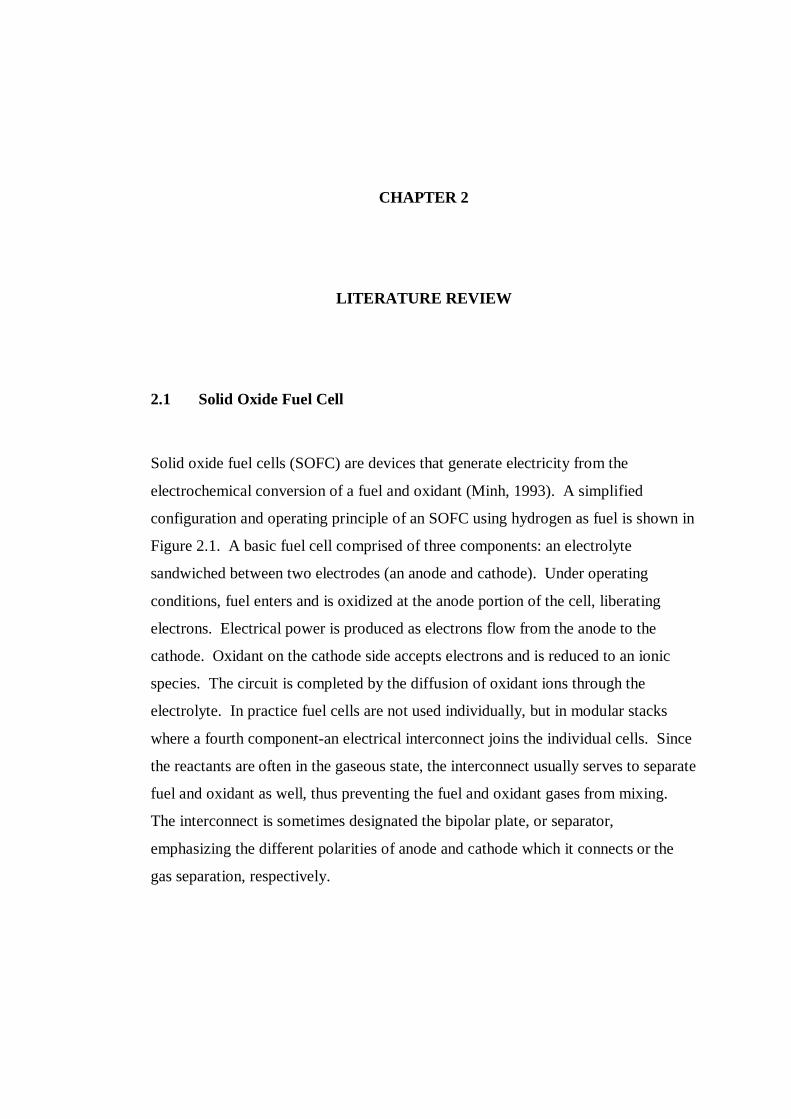
Solid oxide fuel cells (SOFC) are devices that generate electricity from the
electrochemical conversion of a fuel and oxidant (Minh, 1993). A simplified
configuration and operating principle of an SOFC using hydrogen as fuel is shown in
Figure 2.1. A basic fuel cell comprised of three components: an electrolyte
sandwiched between two electrodes (an anode and cathode). Under operating
conditions, fuel enters and is oxidized at the anode portion of the cell, liberating
electrons. Electrical power is produced as electrons flow from the anode to the
cathode. Oxidant on the cathode side accepts electrons and is reduced to an ionic
species. The circuit is completed by the diffusion of oxidant ions through the
electrolyte. In practice fuel cells are not used individually, but in modular stacks
where a fourth component-an electrical interconnect joins the individual cells. Since
the reactants are often in the gaseous state, the interconnect usually serves to separate
fuel and oxidant as well, thus preventing the fuel and oxidant gases from mixing.
The interconnect is sometimes designated the bipolar plate, or separator,
emphasizing the different polarities of anode and cathode which it connects or the
gas separation, respectively.
8
Figure 2.1: Typical SOFC single cell configuration (Minh, 1993)
For basic hydrogen SOFC, the electrochemical reactions involved are shown
below (Minh, 1993):
Anode: (2.1)
Cathode: (2.2)
Overall: (2.3)
Since the energy stored in the fuel is converted electrochemically and not
through combustion, it is not subject to Carnot cycle limitations, so the energetic
efficiency of a fuel cell is significantly higher (~60%) (Singhal, 2003; Steele, 2001).
If the heat produced by the fuel cell is recaptured, efficiencies can reach ~80%. Fuel
cells also produce much less polluting by products than traditional combustion
processes. Additional advantages of fuel cells previously mentioned include their
modular construction and potential for cogeneration of energy (electrical and
thermal) (Minh, 1993).
The fuel and oxidant could, in theory, be any combination of gases that would
provide the electrochemical reaction required for power generation to occur.
Hydrogen is by far the most common fuel in use. The hydrogen can be in the form
eOHOH 222
2
22 2
21 OeO
OHOH 222 21
9
of pure hydrogen gas, methane, or alcohols. The oxidant most commonly used is
oxygen which is introduced into the SOFC in the form of natural air or as a pure gas.
With these common gases, the fuel cell reaction produces by-products of water
vapour and heat.
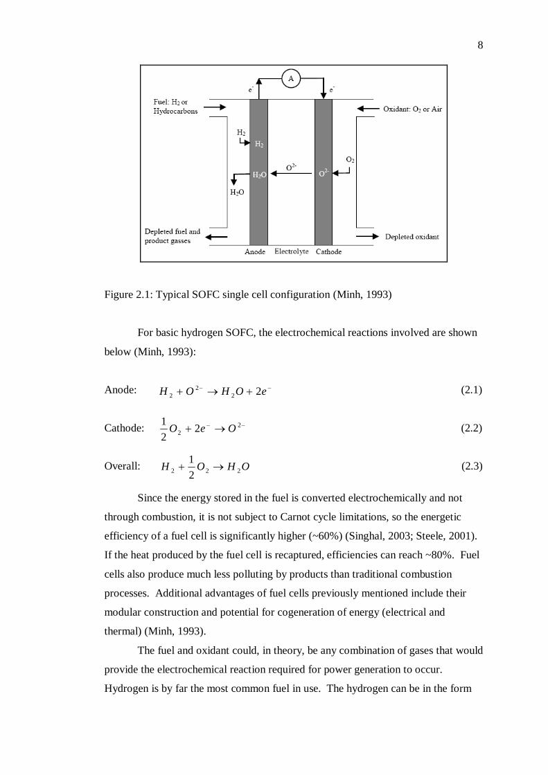
The flat-plate or planar type of SOFC has been the subject of intense research
due to its potential for becoming an efficient, high energy-density power generation
device. A schematic of a planar SOFC (Linderoth, Hendriksen, Mogensen &
Langvad, 1996) is shown in Figure 2.2. The structure is comprised of individual
layers of anode, electrolyte, cathode, and interconnect materials. The power capacity
of a single cell is limited. The individual cells can be layered, or stacked, to form
multi-cell structures thereby providing a higher voltage and power generation
capabilities. Therefore, the structure requires a current collector between different
cells to provide a higher voltage and power which provided by the interconnect.
Figure 2.2: Schematic of a typical planar SOFC stack (Linderoth et al., 1996)
2.2 Interconnect
The interconnect is the most complex of the four fuel cell components. The
interconnect serves several vital functions in the SOFC structure. First, it provides
electrical contact between cells allowing the stack to function as a single power
generation unit. In addition, the interconnect keeps the oxidant and fuel gases from
10
mixing by forming a dense, physical barrier between the repeating cells. In certain
designs, the interconnect may also provide mechanical support to the SOFC
structure. The availability of a suitable material for the interconnect is of key
importance for SOFC development.
The traditional material used for the SOFC interconnect is lanthanum
chromites (LaCrO3). This material exhibits a remarkable high electric conductivity
under SOFC operating conditions (Minh, 1993). Lanthanum chromites meet most of
the above requirements and have proven to be suitable for conventional ceramic fuel
cells. However the largest drawbacks for these materials are their high cost and poor
sintering behaviour, which prevents their gas tightness (Minh, 1993). Also, LaCrO3
is ceramic, processing methods are limited which results in limitations as to the
geometry of interconnect that can be fabricated. Because of these weaknesses of
LaCrO3, significant research efforts have been made to find an alternative material.
Metal alloys are widely seen as possessing superior properties compared with
LaCrO3 which offer the potential to increase efficiency of the SOFC. Metals
generally have very high electrical conductivity. Since any decrease in resistance of
the cell would translate directly into increased output, moving to a more electrically
conductive interconnect material could offer significant advantages. Thermal
conductivity for metals is generally higher than for ceramics. Incorporating a high
thermal conductivity material into a SOFC stack would serve to reduce temperature
gradients within the structure that could impact thermal stresses and stack efficiency.
Metals are generally easy to fabricate into a wide variety of shapes, which would
allow designers to fabricate more complex SOFC designs. Also, many metals and
alloys are relatively inexpensive and readily available.
Metallic alloys, however, also bring several negatives along with these
potential benefits. The two main negative aspects of metal alloys for SOFC
interconnects are oxidation of the metal during operation and the potential for
problems arising due to thermal expansion mismatch between the metal and other
SOFC materials. In a broad sense, metals tend to have higher coefficient of thermal
expansion (CTE) compared with ceramics. In terms of the SOFC, this can cause
significant levels of stress to develop when temperature changes. Metals also tend to
oxidize when exposed to the range of temperatures and atmospheres commonly seen
during operation of a SOFC. Excessive oxidation could lead to such problems as
11
reduced efficiency due to higher surface resistance of the interconnect layer. A
discussion of potential interconnect alloys is given later in this section.
In general terms, the properties which a metal interconnect should possess
can be described as follows (Quadakkers et al., 2003; Zhu & Deevi, 2003a):
i) Thermal expansion. The thermal expansion of the interconnect metal should
match with the other materials in the SOFC. It is particularly important that the
alloy match well with the electrolyte, around 10.5 10-6/oC, so that the thermal
stress developed during start-up and shut-down could be minimized.
ii) Oxidation resistance. The alloy must not corrode severely under the operating
conditions of the fuel cell in both anode and cathode atmospheres. The
parabolic rate constant value for interconnect material is required below 10-14
g2 cm-4 s-1, and a value below 10-15 g2 cm-4 s-1 would be ideal. Furthermore, the
oxidation layer of the interconnect should exhibit some degree of electrical
conductivity and should be adherent to the base alloy.
iii) Electrical conductivity. The acceptable area-specific resistances (ASR) value
for interconnect material is considered to be below 100 mΩcm2.
iv) Thermodynamic stability. The alloy must be thermodynamically stable during
processing and operation of the SOFC. Because, the interconnect is exposed to
both oxidizing conditions at the cathode and reducing conditions at the anode.
v) Innocuous to other SOFC materials. The alloy and its oxidation layer should not
contribute to the chemical degradation of other SOFC materials (i.e. chromia
poisoning of the electrode).
For all these reasons, the interconnect materials constitute one of the basic
components for the functioning and long term reliability SOFC operation stacks.
2.3 Potential Interconnect Alloys
Nowadays, interconnect-concept has been developed using metallic alloys. The
majority of alloys currently investigated for fuel cell interconnects are comprised of
various binary and ternary compositions, such as Cr-based or Fe-Cr binary alloys and
12
Fe-Ni-Cr ternary system. Using these types of materials has the advantage of their
lower costs, easy fabrication and machinability and higher thermal conductivity in
comparison with ceramic interconnects. Nevertheless, metallic alloys show the
problem of a large CTE mismatch than that of the ceramic component, causing large
stresses during cell operation. However, one of the most important features using
these materials is that they are able to form protective oxides at the operating
temperature. The formation of these oxides is of vital importance due to properties
like electrical conductivity that shows a large dependence on them. An example can
be found when an alumina forming alloy is used as interconnect. With such alloys
and at the operating temperature, a very protective alumina oxide layer is formed on
top of the surface, but the main inconvenience is that aluminium oxide has a very
low electrical conductivity (10-6-10-8 Scm-1 at 900 oC) compared with other oxides,
specifically chromium oxide (10-2-10-1 Scm-1 at 900 oC) (Zhu & Deevi, 2003a;
Fergus, 2005). For this reason, the majority of interconnect alloy candidate
researched are chromia formers (Yang et al., 2003).
A metal interconnect must exhibit certain specific properties, several of
which were outlined previously. Many materials can be immediately excluded from
consideration based on these performance criteria and known material properties.
For example, platinum would provide an excellent combination of oxidation
resistance and electrical conductivity but the high material cost would be prohibitive
for the economic production of these devices. Similarly, copper would be relatively
inexpensive and highly conductive, but it would melt during the high-temperature
processing of the hybrid stack. The following section provides an overview of
potential alloy systems, highlighting recent work done and the potential each has for
application as a SOFC interconnect. Several reviews on the topic of potential alloys
for SOFC interconnects have been published recently (Linderoth et al., 1996; Zhu &
Deevi, 2003a; Quadakkers et al., 2003).
2.3.1 Iron-Chromium Alloys
The iron-chromium system has long been used as the basis of many engineering
alloys for high-strength, corrosion-resistant applications. Chromium acts as an -
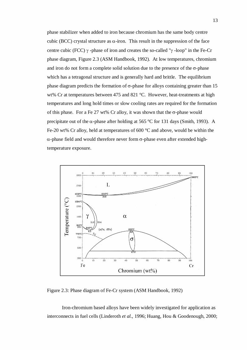
13
phase stabilizer when added to iron because chromium has the same body centre
cubic (BCC) crystal structure as -iron. This result in the suppression of the face
centre cubic (FCC) -phase of iron and creates the so-called "-loop" in the Fe-Cr
phase diagram, Figure 2.3 (ASM Handbook, 1992). At low temperatures, chromium
and iron do not form a complete solid solution due to the presence of the -phase
which has a tetragonal structure and is generally hard and brittle. The equilibrium
phase diagram predicts the formation of -phase for alloys containing greater than 15
wt% Cr at temperatures between 475 and 821 °C. However, heat-treatments at high
temperatures and long hold times or slow cooling rates are required for the formation
of this phase. For a Fe 27 wt% Cr alloy, it was shown that the -phase would
precipitate out of the -phase after holding at 565 °C for 131 days (Smith, 1993). A
Fe-20 wt% Cr alloy, held at temperatures of 600 °C and above, would be within the
-phase field and would therefore never form -phase even after extended high-
temperature exposure.
Figure 2.3: Phase diagram of Fe-Cr system (ASM Handbook, 1992)
Iron-chromium based alloys have been widely investigated for application as
interconnects in fuel cells (Linderoth et al., 1996; Huang, Hou & Goodenough, 2000;

14
Horita et al., 2003a; Mullenberg et al., 2003). Fe-Cr alloys containing between 15
and 40 wt% Cr have been shown to have average CTE values close to that of YSZ
(Linderoth et al., 1996). Oxidation rates of Fe-Cr alloys have been studied at SOFC
operating temperatures in air (Linderoth et al., 1996), wet air, (Mikkelsen &
Linderoth, 2003), and carbon-containing (Horita et al., 2003b) atmospheres.
Linderoth et al. (1996) used commercially provided binary Fe-Cr alloys
ranging in composition from 10 to 60 wt% Cr to study thermal expansion and
oxidation in air. It was shown that the best corrosion resistance was observed from a
Fe 20 wt% Cr sample. The application of a ceria coating on the surface of a bare Fe
40 wt% Cr sample decreased the scale growth at 1000 °C in air by a factor of four
compared with the same alloy without the ceria coating.
Uehara et al. (2003) investigated the impact of small alloying additions to Fe-
Cr alloys containing ~ 20 wt% Cr on the oxidation rate and contact resistance of the
oxide scale. Contact resistance was found to increase with chromium content while
oxidation rate decreased with increasing chromium. The impact of small variations
in Mn, Si, C, and Al additions were not significant in comparison to that due to a
variation in chromium content.
Oxidation of a Fe 22 wt% Cr alloy was studied in wet air and hydrogen at
two water vapour levels by Mikkelsen & Linderoth (2003). It was determined that a
variation in the water vapour content in the oxidizing atmosphere affected oxidation
rate; lower oxidation rates were observed with increased water vapour contents. This
was determined to be due to the fact that wet air facilitated the vaporization of the
chromia from the oxide layer, thereby lowering the observed weight gain of the
sample. In addition, the oxide scale structure was observed to be different for oxides
grown in hydrogen-rich or air atmospheres. Generally, the corrosion/oxidation
resistance is maintained even at high temperature. They are particularly suitable for
applications in aggressive and corrosive environments up to 900°C.
Horita et al. (2003b) studied the oxidation of two commercial Fe-Cr alloys
containing 16 and 22 wt% Cr in a wet methane atmosphere at 800 °C. Results
indicated that a higher chromium-containing alloy would have a slightly lower
oxidation rate in that environment. Electrical conductivity measurements showed
that the 22 wt% Cr alloy had higher conductivity after the oxidation experiment
compared with the 16 wt% Cr alloy. The oxide layers for both alloys were found to
be comprised of Cr2O3 along with Fe-Mn-Cr spinel.
15
Additions of rare-earth elements, specifically Neodymium (Nd) and
Praseodymium (Pr), were shown by Villafañe et al. (2003) to improve the oxidation
resistance of a Fe-Cr alloy in air. Small additions of these elements (~ 0.03 wt%)
were shown to drastically reduce weight gain of Fe 13wt% Cr alloy in air at 800 °C.
It was shown by Ramanathan (1998) that the additions of small amounts of certain
rare earth elements (Y, La) have been well documented in improving the oxidation
protection properties of chromium.
The majority of researches conducted on Fe-Cr based alloys have used
commercially available or supplier-provided experimental alloys. Oxidation
behaviour of the alloy has typically been the main emphasis of research programs
and only passing attention has been given to thermal expansion behaviour and other
properties, such as electrical resistance. When thermal expansion has been
investigated specifically, the published results have not been sufficiently detailed to
allow for an exacting comparison of thermal expansion mismatch between the metal
and electrolyte material. Presenting data in the form of versus temperature allows
for a more complete picture of the material’s behaviour. Therefore, Fe-Cr binary
alloys were developed in the present work from the perspective of finding an alloy
with sufficient properties of oxidation resistance, high-temperature electrical
resistance and thermal expansion.
2.3.2 Other Metallic Materials
Other categories of chromia forming alloys including Ni(-Fe)-Cr base and
Fe(-Ni)-Cr base alloys (e.g., austenitic stainless steels) have a FCC substrate
structure. In comparison to the ferritic stainless steel (FSS), the FCC base alloys, in
particular the Ni(-Fe)-Cr base alloys, are generally much stronger and potentially
more oxidation resistant in the SOFC interconnect operating environment (Fergus,
2005; Linderoth et al, 1996; Yang et al., 2006a). However, the FCC Ni(-Fe)-Cr
base alloys with sufficient Cr for an appropriate oxidation resistance often exhibit a
high CTE, typically in the range of 15.0 to 20.0 10-6/oC from room temperature to
800 oC, and are much more expensive than the FSS. Due to the CTE mismatch,
significant power loss or degradation in performance has been observed during
16
thermal cycling test of stacks using Ni(-Fe)-Cr base alloy interconnects (Wu & Liu,
2010).
The binary Fe-Ni alloys are generally not considered since this system fails to
produce an adherent and protective oxide layer. The oxides of iron (FeO, Fe2O3, and
Fe3O4) form non-uniform layers that spall under fuel cell condition. NiO similarly
does little impede diffusion and protect the alloy. Due to these reasons, little
attention has been paid to this system for interconnects.
Nevertheless, Ni(-Fe)-Cr base alloys may find application as interconnect
materials through the use of innovative SOFC stack and seal designs and novel
interconnect structures. For example, a cladding approach has been applied to
fabricate a stable composite interconnect structure consisting of FCC Ni-Cr base
alloy claddings on a BCC FSS substrate (Chen, et al., 2005a; Chen et al., 2006). The
clad structure appeared to be stable over 1000 hours at 800oC in air and exhibited a
linear CTE close to that of the FSS, but needs further long-term stability evaluation
before its commercial use.
Nickel-chromium alloys have not received significant attention as potential
SOFC interconnect alloys (Yang, et al., 2003) a notable exception generally because
of the high CTE values observed in this system. In addition, these alloys are
generally more expensive than other oxidation-resistant alloys due to the high nickel
contents.
Traditional alloy design emphasizes surface and structural stability, but not
the electrical conductivity of the scale formed during oxidation. In SOFC
interconnect applications; the oxidation scale is part of the electrical circuit, so its
conductivity is important. Thus, alloying practices used in the past may not be fully
compatible with high-scale electrical conductivity. For example, Si, often a residual
element in alloy substrates, leads to formation of a silica sublayer between scale and
metal substrate. Immiscible with chromia and electrically insulating (Kofstad, 1983),
the silica sublayer would increase electrical resistance, in particular if the subscale is
continuous.
17
2.4 Consolidation Processing Route
It is well-known that materials with the same nominal composition can be produced
in different ways, from classical melting and casting, practiced by conventional
metallurgy, via powder consolidation by powder metallurgy methods, combustion
synthesis with thermo-mechanical treatment, etc. Each technological route produces
material having different microstructure, different concentrations and types of
defects and therefore totally different properties. The first step in obtaining high-
performance metal with a homogeneous microstructure and controlled grain size that
meet the requirements of SOFC application is to prepare powders metal with
controlled stoichiometry and small particle size. However, even if a small-size
powder is used, conventional sintering is often unable to provide dense, very fine-
grained metal, due to the high temperatures still required for densification.
Figure 2.4: The three steps of sintering (Assollant, 1993; Kang, 2005)
In solid phase sintering (Figure 2.4), the temperature of the thermal treatment
is slightly above two-thirds of the melting point. Sintering is subject of many
influences: powder characteristics (morphology, dimension of the grains, purity,
etc.), treatment (temperature, pressure, holding time) and atmosphere (vacuum,
18
reducing, oxidizing or inert (Ar, N2)). The sintering process of the solid sample is
considered to be thermodynamically irreversible. It is expressed by a lessening of
the surface energy (free surface of the grains, then surfaces of the open and closed
pores). Three steps are defined during the sintering (Assollant, 1993; Kang, 2005):
i) Formation of a zone of connection between grains, called the bridge or neck of
matter. This phenomenon is activated by diffusion mechanisms, evaporation-
condensation, plastic deformation, etc., and ends when the bridges have been
raised by close to 50% of the grain radii. This step is accompanied by an
increase of ~15% of the density.
ii) Elimination of the residual cavities or pores, the size of which is directly related
to the surface energy. Being inter-connected, they form a continuous porosity,
which diminishes and drives to a compactness of around 90%. Some cavities
being instable will lead to some isolated pores.
iii) The final step corresponds to almost full disappearance of the porosity, giving a
fully dense material. Note that the grains tend to grow in this last step.
To take the advantage of the unique properties of the high performance
nanostructured material the nanometer range powder particles have to be
consolidated nearer to full theoretical density of the material, i.e. after consolidation
nanofeatures should be retained in the densified material. To achieve this it has to
restrict the grain growth or coarsening during densification. Therefore, the
temperature and time of consolidation are to be restricted at low value in order to
achieve smaller grain sizes.
Among the methods reported for activation of the mass transport during the
sintering process, the application of an electrical current through the sample during
heating represents a promising technique for rapid densification of metal at relatively
low temperatures. The most novel and increasingly used method is spark plasma
sintering, which has clear advantages over conventional sintering methods, such as
hot pressing, making it possible to sinter nanometric powder to near full densification
with little grain growth.
This has become increasingly important recently, with the high thermal
stability application in SOFC system and the need to investigate size effects on the
properties in approaching the nanometer scale. Therefore, the two consolidation
19
methods are used for sintering Fe-Cr powder in this work: the SPS and the HP.
Figure 2.5 shows generally the powder metallurgy route which had been explored in
this project.
Figure 2.5: Powder metallurgy route 2.5 Sintering
Sintering is a process of using heat to turn powdered substances into solids without
actually melting the material and is the most common technique for consolidating
powders. During sintering, the pressed powder particles fuse together, forming
metallurgical bonds. Essentially, it is the removal of the pores between the starting
particles, combined with their growth and strong mutual bonding. The process is
carried out by heating up the “green” part at about 70 to 80 % of the melting
temperature, until full strength is obtained within several minutes to hours. The
biggest problem of this technique is the shrinkage which causes cracking and
distortion. There are many methods of sintering a component. The process is
usually divided in four categories: solid-state sintering; liquid-phase sintering,
viscous flow sintering; and transient liquid phase sintering. Overpressure sintering
uses also pressure to accelerate densification. In this work, the mechanically alloyed
Metal Powders
Hot Pressing Spark Plasma Sintering
Secondary & Finishing Operations
20
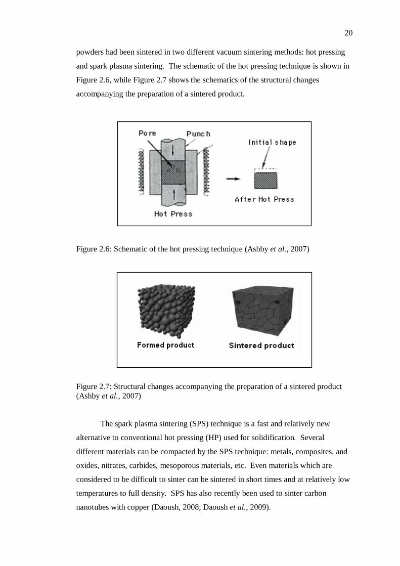
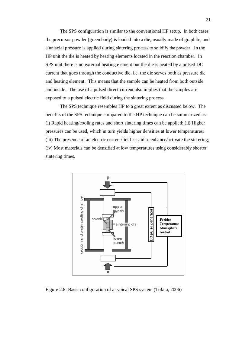
powders had been sintered in two different vacuum sintering methods: hot pressing
and spark plasma sintering. The schematic of the hot pressing technique is shown in
Figure 2.6, while Figure 2.7 shows the schematics of the structural changes
accompanying the preparation of a sintered product.
Figure 2.6: Schematic of the hot pressing technique (Ashby et al., 2007)
Figure 2.7: Structural changes accompanying the preparation of a sintered product (Ashby et al., 2007)
The spark plasma sintering (SPS) technique is a fast and relatively new
alternative to conventional hot pressing (HP) used for solidification. Several
different materials can be compacted by the SPS technique: metals, composites, and
oxides, nitrates, carbides, mesoporous materials, etc. Even materials which are
considered to be difficult to sinter can be sintered in short times and at relatively low
temperatures to full density. SPS has also recently been used to sinter carbon
nanotubes with copper (Daoush, 2008; Daoush et al., 2009).
21
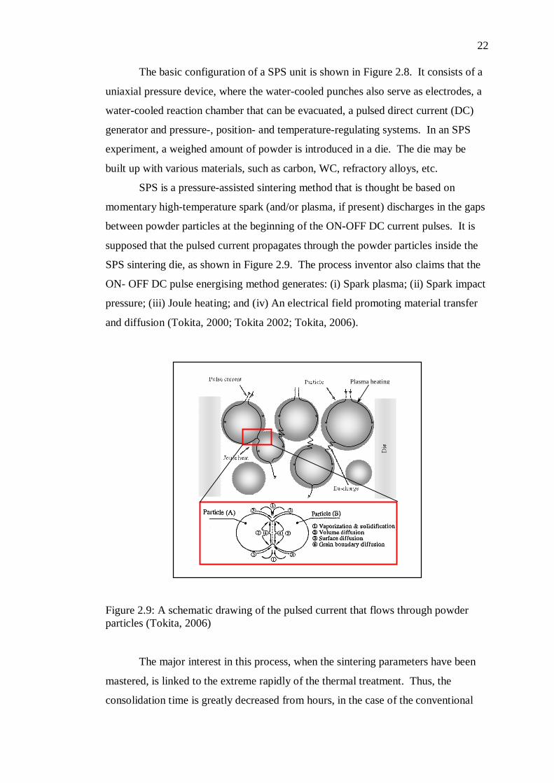
The SPS configuration is similar to the conventional HP setup. In both cases
the precursor powder (green body) is loaded into a die, usually made of graphite, and
a uniaxial pressure is applied during sintering process to solidify the powder. In the
HP unit the die is heated by heating elements located in the reaction chamber. In
SPS unit there is no external heating element but the die is heated by a pulsed DC
current that goes through the conductive die, i.e. the die serves both as pressure die
and heating element. This means that the sample can be heated from both outside
and inside. The use of a pulsed direct current also implies that the samples are
exposed to a pulsed electric field during the sintering process. The SPS technique resembles HP to a great extent as discussed below. The
benefits of the SPS technique compared to the HP technique can be summarized as:
(i) Rapid heating/cooling rates and short sintering times can be applied; (ii) Higher
pressures can be used, which in turn yields higher densities at lower temperatures;
(iii) The presence of an electric current/field is said to enhance/activate the sintering;
(iv) Most materials can be densified at low temperatures using considerably shorter
sintering times.
Figure 2.8: Basic configuration of a typical SPS system (Tokita, 2006)
22
The basic configuration of a SPS unit is shown in Figure 2.8. It consists of a
uniaxial pressure device, where the water-cooled punches also serve as electrodes, a
water-cooled reaction chamber that can be evacuated, a pulsed direct current (DC)
generator and pressure-, position- and temperature-regulating systems. In an SPS
experiment, a weighed amount of powder is introduced in a die. The die may be
built up with various materials, such as carbon, WC, refractory alloys, etc.
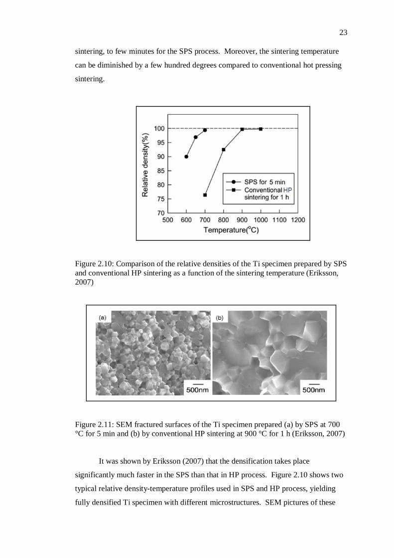
SPS is a pressure-assisted sintering method that is thought be based on
momentary high-temperature spark (and/or plasma, if present) discharges in the gaps
between powder particles at the beginning of the ON-OFF DC current pulses. It is
supposed that the pulsed current propagates through the powder particles inside the
SPS sintering die, as shown in Figure 2.9. The process inventor also claims that the
ON- OFF DC pulse energising method generates: (i) Spark plasma; (ii) Spark impact
pressure; (iii) Joule heating; and (iv) An electrical field promoting material transfer
and diffusion (Tokita, 2000; Tokita 2002; Tokita, 2006).
Figure 2.9: A schematic drawing of the pulsed current that flows through powder particles (Tokita, 2006)
The major interest in this process, when the sintering parameters have been
mastered, is linked to the extreme rapidly of the thermal treatment. Thus, the
consolidation time is greatly decreased from hours, in the case of the conventional
Plasma heating
23
sintering, to few minutes for the SPS process. Moreover, the sintering temperature
can be diminished by a few hundred degrees compared to conventional hot pressing
sintering.
Figure 2.10: Comparison of the relative densities of the Ti specimen prepared by SPS and conventional HP sintering as a function of the sintering temperature (Eriksson, 2007)
Figure 2.11: SEM fractured surfaces of the Ti specimen prepared (a) by SPS at 700 °C for 5 min and (b) by conventional HP sintering at 900 °C for 1 h (Eriksson, 2007)
It was shown by Eriksson (2007) that the densification takes place
significantly much faster in the SPS than that in HP process. Figure 2.10 shows two
typical relative density-temperature profiles used in SPS and HP process, yielding
fully densified Ti specimen with different microstructures. SEM pictures of these
24
samples are shown in Figure 2.11. The average grain size was noticeably different
depending on the sintering method, as shown in SEM micrograph (Figure 2.11). In
conventional HP sintering, the specimen was fully densified after sintering at
temperatures above 900 °C for 1 h. In contrast, when the samples were prepared by
SPS, the relative density of the theoretical value was reached 99% at 700 °C.
Moreover, even 5 min of treatment using SPS at 600–700 °C resulted in a
significantly high density (95 - 99%). A comparison of the two densification curves
obtained from conventional HP sintering and SPS indicates that employing SPS
effective in obtaining fully-densified specimen with a minimum grain growth at a
low sintering temperature by approximately 200 °C. This also shows that SPS
constitute an innovative technique in the field of material sintering and three
distinguishing factors contribute to its enhanced densification compared to
conventional HP process: i) DC current influence, ii) high heating rates, and, iii) the
simultaneous application of pressure.
2.6 Surface Treatments via Ion Implantation
Thermal stability of the metallic interconnect can influence to an efficiency of the
stack such as the increased electrical resistance due to the growth of oxide layer.
There are two general methods used to improve the thermal stability of an alloy;
alloying addition and surface treatment such as by ion implantation. Of these two
methods, only surface treatments – ion implantation are discussed here.
Ion Implantation is a physical method for the modification of surface
properties of materials by insertion of accelerated atoms, within the first atomic
layers into solid substrates. Ionized atoms are made to accelerate and to bombard the
solid surface. As a consequence, there can be distinct modifications to near-surface
microstructure and chemical, physical and mechanical properties which for example
can appear as changes in corrosion behaviour, electrical properties, stiffness,
hardness, wear resistance, friction response, or other surface-region-sensitive
mechanical properties such as fatigue and contact fracture toughness. Nowadays,
this technique is commonly employed for the surface treatment of cutting and
95
REFERENCES
Ailor, W.H. (1971). Handbook of Corrosion Testing and Evaluation. New York:
John Wiley.
Antepara, I., Villarreal, I., Rodríguez-Martínez, L. M., Lecanda, N., Castro, U., &
Laresgoiti, A. (2005). Evaluation of ferritic steels use as interconnects and
porous metal supports in IT-SOFCs. J. Power Sources, 151, pp. 103 – 107.
Ashby, M., Sherclif, H., & Cebon, D. (2007). Materials: Engineering, Science,
Processing and Design. Oxford: Elsevier.
ASM Handbook Vol. 3. (1992). Alloy Phase Diagrams. Materials Park, OH: ASM
International.
Assollant, D. B. (Ed) (1993). Chimie-physique du frottage (in English version). Paris:
Hermes FORCERAM Collection.
Benenson, W., Harris, J. W., Stocker, H., & Lutz, H. (2002). Handbook of Physics.
New York: Springer-Verlag Inc.
Bloor, Brook, Flemings, & Mahajan. (1994). Ion Implantation. The Encyclopedia of
Advanced Material. Oxford: Pergamon.
Chen, L., Yang, Z., Jha, B., Xia, G., & Stevenson, J. W. (2005a). Clad metals, roll
bonding and their applications for SOFC interconnects. J. Power Sources,
152(1), pp. 40 – 45.
102
Chen, L., Jha, B.,Yang, Z., Xia, G., Stevenson, J. W., & Singh, P. (2006). Clad
metals by roll bonding for SOFC interconnects. J. Mater. Eng. Perform,
15(4), pp. 399 – 403.
Chen, X., Hou, P. Y., Jacobson, C. P., Visco, S. J., & De Jonghe, L. C. (2005b).
Protective coating on stainless steel interconnect for SOFCs: Oxidation
kinetics and electrical properties, Solid State Ionics, 176, pp. 425–433.
Cooper, L., Benhaddad, S., Wood, A., & Ivey, D. G. (2008). The effect of surface
treatment on the oxidation of ferritic stainless steel used for solid oxide fuel
cell interconnects. Journal of Power Sources, 184, pp. 220–228.
Daoush, W. M. (2008). Processing and characterization of CNT/Cu nanocomposites
by powder technology. Powder Metallurgy and Metal Ceramics, 47(9/10),
pp. 531 - 537.
Daoush, W. M., Lim, B. K., Mo, C. B., Nam, D. H., & Hong, S. H. (2009). Electrical
and mechanical properties of carbon nanotube reinforced copper
nanocomposites fabricated by electroless deposition process. Materials
Science and Engineering: A, 513-514(C), pp. 247 - 253.
Ding, W., Wang, X., Zeng, X., Wu, G., Yao, S., & Lai, Y. (2007). Cyclic oxidation
behavior of Cerium implanted AZ31 magnesium alloys. Materials Letters,
61, pp. 1429 – 1432.
Dyos, G. T. & Farrel, T. (1992). Electrical Resistivity Handbook. London: Peter
Peregrinus Ltd.
Echsler, H., Martinez, E. A., Singheiser, L., & Quadakkers, W. J. (2004). Residual
stresses in alumina scales grown on different types of Fe–Cr–Al alloys:
Effect of specimen geometry and cooling rate. Materials Science and
Engineering A, 384, pp. 1 – 11.
103
Eriksson, M. (2007). Spark Plasma Sintering and Deformation Behaviour of
Titanium and Titanium/TiB2 Composites, Division of Inorganic Chemistry,
Stockholm University: Licentiate Thesis.
Essuman, E., Meier, G. H., Zurek, J., Hansel, M., Singheiser, L., & Quadakkers, W.
J. (2007). Enhanced internal oxidation as trigger for breakaway oxidation of
Fe–Cr alloys in gases containing water vapor. Scripta Materialia, 57, pp. 845
– 848.
Fergus, J. W. (2005). Metallic interconnects for solid oxide fuel cells. Materials
Science and Engineering A, 397, pp. 271 – 283.
Fernandes, S. M. D. C., & Ramanathan, L.V. (2007). Cyclic oxidation resistance of
rare earth oxide gel coated Fe-20Cr alloys. Materials Research, 10(3), pp.
321 - 324.
Filetin, T. (2001). An Overview of the Development and Application of Advanced
Materials. Zagreb: Croatian Welding Society.
Fontana, M. G. (1986). Corrosion Engineering. 3rd ed. International Student Edition.
New York: McGraw-Hill.
Fontana, S., Amendola, R., Chevalier, S., Piccardo, P., Caboche, G., Viviani, M.,
Molins, R., & Sennour, M. (2007). Metallic interconnects for SOFC:
Characterisation of corrosion resistance and conductivity evaluation at
operating temperature of differently coated alloys. Journal of Power Sources,
171, pp. 652 – 662.
Gao, W. & Li, Z. (2004). Nano-structured alloy and composite coatings for high
temperature applications. Material Research, 7(1), pp. 175-182.
Gupta, R. K., Singh Raman, R. K., & Koch, C. C. (2010). Fabrication and oxidation
resistance of nanocrystalline Fe10Cr alloy. J. Mater. Sci., 45, pp. 4884–4888.
104
Horita, T., Xiong, Y., Yamaji, K., Sakai, N., & Yokokawa, H. (2003a).
Characterization of Fe-Cr alloys for reduced operation temperature SOFCs.
Journal of the Electrochemical Society, 2, pp. 189-194.
Horita, T., Xiong, Y., Yamaji, K., Sakai, N., & Yokokawa, H. (2003b). Stability of
Fe-Cr alloy interconnects under CH4-H2O atmosphere for SOFCs. Journal of
Power Sources, 118(1), pp.35-43.
Huang, K., Hou, P. Y., & Goodenough, J. B. (2000). Characterization of iron-based
alloy interconnects for reduced temperature solid oxide fuel cells. Solid State
Ionics, 129(1), pp. 237 - 250.
Kang, S. J. L. (2005). Sintering: Densification, Grain Growth, and Microstructure.
Oxford: Elsevier.
Kofstad, P. (1983). Nonstoichiometry, Diffusion, and Electrical Conductivity in
Binary Metal Oxides. Florida: Robert E. Krieger Publishing Company.
Kofstad, P. (1988). High Temperature Corrosion. New York: Elsevier Applied
Science.
Kuru, Y., Wohlschlogel, M., Welzel, U., & Mittemeijer, E. J. (2007). Crystallite size
dependence of the coefficient of thermal expansion of metals. Applied
Physics Letters, 90, pp. 243113-1 – 243113-3.
Larsen, P. H., Hendriksen, P. V., & Mogensen, M. (1997). Dimensional stability and
defect chemistry of doped lanthanum chromites. J. Thermal Analysis, 49, pp.
1263 – 1275.
Li, M.-S., Qian, Y.-H., & Zhou, Y.-C. (2008). Oxidation of pre-oxidized GH128
alloy implanted with Ce+ at 1000 oC. Trans. Nonferrous Met. Soc. China, 18,
pp. 493 – 498.
105
Linderoth, S., Hendriksen, P.V., Mogensen, M., & Langvad, N. (1996).
Investigations of metallic alloys for use as interconnects in solid oxide fuel
cell stacks. Journal of Materials Science, 31, pp. 5077 - 5082.
Marest, G. (1998). Surface treatment by ion implantation. Hyperfine Interactions,
111, pp. 121 -127.
Minh, N.Q. (1993). Ceramic fuel cells. Journal of the American Ceramic Society,
76(3), pp. 563 - 588.
Mullenberg, W. A. Uhlenbruck, S., Wessel, E., Buchkremer, H. P., & Stover, D.
(2003). Oxidation behaviour of ferrous alloys used as interconnecting
material in solid oxide fuel cells. Journal of Materials Science, 38, pp. 507.
Mikkelsen, L. & Linderoth, S. (2003). High temperature oxidation of Fe-Cr alloy in
O2-H2-H2O atmospheres; microstructure and kinetics. Materials Science and
Engineering A, 361, pp.198 - 212.
Monceau, D. & Pieraggi, B. (1998). Determination of parabolic rate constants from a
local analysis of mass-gain curves. Oxidation of Metals, 50(5/6), pp. 477-493.
Omori, M. (2000). Sintering, consolidation, reaction and crystal growth by the spark
plasma system (SPS). Material Science and Engineering A, 287, pp. 183 -
188.
Peng, H. (2004). Spark Plasma Sintering of Si3N4-Based Ceramics: Sintering
Mechanism-Tailoring Microstructure-Evaluating Properties, Department of
Inorganic Chemistry, Stockholm University: Ph.D Thesis.
Pilis, M. F. & Ramanathan, L. V. (2007). High temperature oxidation resistance of
rare earth chromite coated Fe-20Cr and Fe-20Cr-4Al alloys. Materials
Research, 10(3), pp. 279 – 282.
106
Quadakkers, W.J., Abellan, J. P., Shemet, V., & Singheiser, L. (2003). Metallic
interconnectors for solid oxide fuel cells – a review. Materials at High
Temperatures, 20(2), pp. 115 - 127.
Ramanathan, L. V. (1998). Corrosion control with rare earths. Corrosion Prevention
and Control, 45(3), pp. 87 - 92.
Riffard, F., Buscail, H., Caudron, E., Cueff, R., Issartel, C., & Perrier, S. (2006). The
influence of implanted Yttrium on the cyclic oxidation Behaviour of 304
Stainless Steel. Applied Surface Science, 252, pp. 3697 – 3706.
Saryanto, H. (2011). High Temperature Oxidation Resistance of Nanocrystalline
Fe80Cr20 Alloys and Ferritic Steel Implanted with Lanthanum and Titanium,
Faculty of Mechanical and Manufacturing Engineering, Universiti Tun
Hussein Onn Malaysia: Master Thesis.
Sebayang, D., Khaerudini, D. S. Saryanto, H., Othman, M. A. Sujitno, T., & Untoro,
P. (2011). Effect of nanocrystalline and Ti implantation on the oxidation
behaviour of Fe80Cr20 alloy and commercial ferritic steel. Key Engineering
Materials, 474-476, pp. 2134-2139.
Shaigan, N., Qu, W., Ivey, D. G., & Chen, W. (2010). A review of recent progress in
coatings, surface modifications and alloy developments for solid oxide fuel
cell ferritic stainless steel interconnects. Journal of Power Sources, 195, pp.
1529 - 1542.
Shiratori, Y., Tietz, F., Buchkremer, H. P., & Stover, D. (2003). YSZ–MgO
composite electrolyte with adjusted thermal expansion coefficient to other
SOFC components. Solid State Ionics, 164, pp. 27–33.
Singhal, S. (2003). Ceramic fuel cells for stationary and mobile applications.
American Ceramic Society Bulletin, pp. 9601 - 9610.
107
Smith, W. F. (1993). Structure and Properties of Engineering Alloys. 2nd ed. New
York: McGraw-Hill.
Smith, W. F. (1996). Principles of Materials Science and Engineering. New York:
Mc Graw-Hill.
Steele, B. C .H. (2001). Material science and engineering: The enabling technology
for the commercialisation of fuel cell systems. Journal of Materials Science,
36, pp. 1053 - 1068.
Stöver, D., Diekmann, U., Flesch, U., Kabs, H., Quadakkers, W. J., Tietz, F., &
Vinke, I. (1999). Recent developments in anode supported thin film SOFC at
Research Centre Jülich. Proceedings 6th International Symposium Solid Oxide
Fuel Cells (SOFC-VI), Pennington, NJ, The Electrochemical Society, pp. 812
- 821.
Suryanarayana, C. (2004). Mechanical Alloying and Milling. New York: Marcel
Dekker.
Taylor, R. E. (1998). Thermal Expansion of Solids. Ohio: ASM International.
Tietz, F., Buchkremer, H. -P., & Stöver, D. (2002). Components manufacturing for
solid oxide fuel cells. Solid State Ionics, 152-153, pp. 373 – 381.
Tietz, F. (1999). Thermal expansion of SOFC materials. Ionics, 5, pp. 129 - 139.
Tokita, M. (2000). Current status of spark plasma sintering. Sokeizai, 41, pp. 8 - 13.
Tokita, M. (2002). Spark plasma sintering apparatus. Nanoryushi no Seizo-Hyoka-
Oyo-Kiki no Saishin Gijutsu, pp. 146-153.
Tokita, M. (2006). Innovative sintering process-spark plasma sintering (SPS).
Materials Integration, 19(12), pp. 42 - 50.
108
Uehara, T., Toji, A., Inoue, K., Yamaguchi, M., & Ohno, T. (2003). Solid Oxide Fuel
Cells VIII Proceedings of the International Symposium, Pennington, N.J. The
Electrochemical Society, pp. 915.
Villafañe, A. M., Chacon-Nava, J. G. Gaona-Tiburcio, C., Calderon, F. A., Patiño, G.
D., & Gonzalez-Rodriguez, J. G. (2003). Oxidation performance of a Fe-13Cr
alloy with additions of rare earth elements. Materials Science and
Engineering A, 363, pp. 15.
Williamson, G. K. & Hall, W. H. (1953). X-ray line broadening from filed
aluminium and wolfram. Acta Metallurgica, 1, pp. 22 – 31.
Wu, J. & Liu, X. (2010). Recent development of SOFC metallic interconnect. J.
Mater. Sci. Technol., 26(4), pp. 293 – 305.
Yang, Z. G., Weil K. S., Paxton, D. M., & Stevenson, J. W. (2003). Selection and
evaluation of heat-resistant alloys for SOFC interconnect applications.
Journal of the Electrochemical Society, 150(9), pp. A1188 - A1201.
Yang, Z., Xia, G., Singh, P., & Stevenson, J.W. (2006a). Evaluation of Ni-Cr-base
alloys for SOFC interconnect applications. Journal of Power Sources, 160(2),
pp. 1104 – 1110.
Yang, Z., Xia, G., Singh, P., & Stevenson, J.W. (2006b). Electrical contacts between
cathodes and metallic interconnects in solid oxide fuel cells. Journal of
Power Sources, 155, pp. 246 – 252.
Young, D. (2008). High Temperature Oxidation and Corrosion of Metals.
Amsterdam: Elsevier.
Zhang, H. W., Gopalan, R., Mukai, T., & Hono, K. (2005). Fabrication of bulk
nanocrystalline Fe–C alloy by spark plasma sintering of mechanically milled
powder. Scripta Materialia, 53, pp. 863 – 868.

109
Zhu, W. Z. & Deevi, S. C. (2003a). Development of interconnect materials for solid
oxide fuel cells. Materials Science and Engineering A, 348, pp. 227 - 243.
Zhu, W. Z. & Deevi, S. C. (2003b). Opportunity of metallic interconnects for solid
oxide fuel cells: a status on contact resistance. Materials Research Bulletin,
38, pp. 957 – 972.