
Development of Fuzzy Manifold and Fuzzy Nearest Distance ... · Development of Fuzzy Manifold and...
6
Development of Fuzzy Manifold and Fuzzy Nearest Distance for Pose Estimation of Degraded Face Images BENYAMIN KUSUMOPUTRO*, BRAHMASTRO KRESNARAMAN** AND LINA*** * Dept. of Electrical and Electronic Engineering, Faculty of Engineering, University of Indonesia **Faculty of Computer Science, University of Indonesia, Depok, West Java *** Faculty of Information Technology, Tarumanagara University, Jakarta INDONESIA Abstract:- This paper presents a novel approach to estimate the pose position of the degraded face images using fuzzy vector representation. We focus on the development of fuzzy-manifold as an interpolation line between all the available learning data and the fuzzy distance calculation as the classifier. Crisp-based vector of the face image is firstly transformed into fuzzy-based vector, to deal with the fuzziness of the data caused by statistical measurement error directly. Two types of fuzzy interpolation methods are used to construct the fuzzy-manifold. Estimating the pose position of an unknown crisp-image vector is accomplished by firstly transformed into a fuzzy-vector and calculates the nearest fuzzy-distances to all available fuzzy-points in the designated fuzzy-lines. This system is then applied to estimate a degraded face images influenced by quality degradation effects. Experiment results show that those degradation effects due to various noise additions did not decrease the recognition rate. Keywords-fuzzy number; fuzzy vector; fuzzy line interpolation; fuzzy distance calculation. 1. Introduction Automatic face recognition (AFR) has been traditionally associated with the fields of computer science and pattern recognition. Since an AFR is considered to be a natural, non intimidating, and widely accepted biometric identification method [1][2], it has the potential of becoming the leading biometric technology. In the context of face recognition, it is common to distinguish between the problem of verification and that of recognition. In the first case, the enrolled individual claims identity of a person whose template is stored in the database. The face recognition algorithms are developed by comparing a given face image and verify the equivalence with that of a given template. In the second case, recognition implies that the probe subject should be compared with all the templates stored in the gallery of database. The face recognition algorithm should then match a given face image with one of the individuals in the data base, or one-to-many matching problem. In this case, no collaboration can be assumed. Three-dimensional face recognition is a relatively recent trend that in some sense breaks the long-term tradition of mimicking the human visual recognition system. Trying to use 3D information has become an emerging research direction in hope to make face recognition more accurate and robust. Recognizing a known 3-D face image using a single 2-D image is a central and difficult problem in face recognition. We have developed a neural network based 3-D face recognition system that by adding the information of the pose position of the probe image instead of just the 2-D image grayscale information, face recognition of 3-D image can be successfully determined. In this paper, we would like to address the problem on determining the pose of the incoming 3-D face image as a part of the required information for recognizing 3-D face in our system. Researchers take many different approaches to recognize a 3D face images using pose information. Lowe [4] is believed to be the first researcher to introduce the notion that a partial match of image to model features yields constraints on the position in the image of other features of the model due to rigidity constraints. This was generalized by Gaston et.al [5] and Grimson et.al [6] using the term interpretation tree. A LGBP method for estimating head pose estimation has been proposed by Ma et. al [7]. In addition, the Proceedings of the 9th WSEAS International Conference on APPLICATIONS of COMPUTER ENGINEERING ISSN: 1790-5117 180 ISBN: 978-960-474-166-3
Transcript of Development of Fuzzy Manifold and Fuzzy Nearest Distance ... · Development of Fuzzy Manifold and...
Development of Fuzzy Manifold and Fuzzy Nearest Distance for Pose Estimation of Degraded Face Images
BENYAMIN KUSUMOPUTRO*, BRAHMASTRO KRESNARAMAN** AND LINA*** * Dept. of Electrical and Electronic Engineering, Faculty of Engineering, University of Indonesia
**Faculty of Computer Science, University of Indonesia, Depok, West Java *** Faculty of Information Technology, Tarumanagara University, Jakarta
INDONESIA
Abstract:- This paper presents a novel approach to estimate the pose position of the degraded face images using fuzzy vector representation. We focus on the development of fuzzy-manifold as an interpolation line between all the available learning data and the fuzzy distance calculation as the classifier. Crisp-based vector of the face image is firstly transformed into fuzzy-based vector, to deal with the fuzziness of the data caused by statistical measurement error directly. Two types of fuzzy interpolation methods are used to construct the fuzzy-manifold. Estimating the pose position of an unknown crisp-image vector is accomplished by firstly transformed into a fuzzy-vector and calculates the nearest fuzzy-distances to all available fuzzy-points in the designated fuzzy-lines. This system is then applied to estimate a degraded face images influenced by quality degradation effects. Experiment results show that those degradation effects due to various noise additions did not decrease the recognition rate.
Keywords-fuzzy number; fuzzy vector; fuzzy line interpolation; fuzzy distance calculation.
1. Introduction Automatic face recognition (AFR) has been traditionally associated with the fields of computer science and pattern recognition. Since an AFR is considered to be a natural, non intimidating, and widely accepted biometric identification method [1][2], it has the potential of becoming the leading biometric technology.
In the context of face recognition, it is common to distinguish between the problem of verification and that of recognition. In the first case, the enrolled individual claims identity of a person whose template is stored in the database. The face recognition algorithms are developed by comparing a given face image and verify the equivalence with that of a given template. In the second case, recognition implies that the probe subject should be compared with all the templates stored in the gallery of database. The face recognition algorithm should then match a given face image with one of the individuals in the data base, or one-to-many matching problem. In this case, no collaboration can be assumed.
Three-dimensional face recognition is a relatively recent trend that in some sense breaks the long-term
tradition of mimicking the human visual recognition system. Trying to use 3D information has become an emerging research direction in hope to make face recognition more accurate and robust.
Recognizing a known 3-D face image using a single 2-D image is a central and difficult problem in face recognition. We have developed a neural network based 3-D face recognition system that by adding the information of the pose position of the probe image instead of just the 2-D image grayscale information, face recognition of 3-D image can be successfully determined. In this paper, we would like to address the problem on determining the pose of the incoming 3-D face image as a part of the required information for recognizing 3-D face in our system.
Researchers take many different approaches to recognize a 3D face images using pose information. Lowe [4] is believed to be the first researcher to introduce the notion that a partial match of image to model features yields constraints on the position in the image of other features of the model due to rigidity constraints. This was generalized by Gaston et.al [5] and Grimson et.al [6] using the term interpretation tree. A LGBP method for estimating head pose estimation has been proposed by Ma et. al [7]. In addition, the
Proceedings of the 9th WSEAS International Conference on APPLICATIONS of COMPUTER ENGINEERING
ISSN: 1790-5117 180 ISBN: 978-960-474-166-3

authors have also proposed the modified nearest feature line method [8] and spline classification method [9] for a 3D face recognition and a pose estimation system.
To recognize the pose position of the unknown image, we proposed a Fuzzy Manifold as an interpolation line that passing through a fuzzy vector representing the learning images in a Fuzzy Feature space. To estimate the pose position of the unknown data test, we proposed two methods of Fuzzy Nearest Distance calculation. By using these techniques, the robustness of the system is also experimentally tested using degrading 3-D face images.
The remainder of this paper is organized as follows. Section 2 describes the construction of fuzzy vector representation from learning images and a single test image; and the construction of the fuzzy manifold. Section 3 presents the description of the developed fuzzy nearest distance calculation methods and used it as a pose estimation system. Section 4 shows and discuss the performance evaluation in estimating the degraded 3-D face images. Finally, Section 5 presents our conclusion.
2. Fuzzy Representation And Fuzzy
Manifold This section describes the process of constructing the appearance manifold of the all data in the gallery by transforming first into fuzzy representation in fuzzy feature space. As in real applications of pose estimation system, variations in camera-captured images usually occurred naturally. Those variations might occurred during the capturing process, for example, the changing appearance of image due to lighting conditions, incorporating noises on image and degrading images due to data communication procedures.
In a conventional pose estimation system, an image is represented in an array of crisp vector. Previously results on pose estimation with crisp vector representation for a 3-D face images, however, showed that the recognition rate of the system is very low, about 30% in average [9]. To increase the recognition capability of this system, we proposed a fuzzy vector representation instead of crisp vector representation.
In this section we will explain the two steps that necessary to represent the 3-D images into a fuzzy point or fuzzy vector, and to draw an interpolation lines that passing through those fuzzy points that would be called Fuzzy Manifold.
The 3D face pose estimation system described here can be divided into two subsystems, i.e. construction of fuzzy-manifold subsystem and fuzzy-distance calculation subsystem. In this section we will explain the construction of the fuzzy-manifold subsystem, while fuzzy-distance calculation subsystem will be explained in the next section.
The basic idea of constructing the fuzzy-manifold can be divided into two steps, the construction of Fuzzy Point from 3-D face images and the construction of Fuzzy-Manifold that connected all the available Fuzzy Points.
As the developed pose estimation system used fuzzy-vector calculation technique, the images that will be estimated its pose position should also be represented in the fuzzy-number and fuzzy-vector instead of crisp-number and crisp-vector.
2.1. Fuzzy Vector Representation of 3-D Face Images
Generally, the appearance-based approaches deal with a set of learning images in various capturing conditions. Suppose the learning data of 3D image is designated as single crisp-vector F. Then the data images of all persons taken with different expressions at a single pose position are grouped into one set crisp-vectors based. A fuzzification process of the crisp-vector of image data into its fuzzy-vector representation can be explained as follows. For each data set of crisp vector at each position at each feature space, we calculate the minimum, maximum and average value of the grey-level intensity at each dimension. And using those values, a fuzzy vector of images in each pose position can be determined as a normalized triangular fuzzy vector G= (G1,G2,…,Gi,…,Gn) with a normalized triangular fuzzy number Gi can be written as:
),,( rl gggGi = (1) where g the center-peak position of G, gl left part fuzziness and gr right part one. Fuzziness is expressed by the skirt width of the membership function. When an unknown image of an unknown person with unknown expression and unknown pose position is fetched to the system, for estimating its pose position, the image should be firstly transformed into a triangular fuzzy vector.
In this paper, a simple transformation manipulation technique is proposed. As already explained, the image crisp-vector F is transformed into its fuzzy-vector G by calculating the minimum, maximum and average values at each dimension. For all of the used data, we calculate the skirt width of the minimum and maximum values of
Proceedings of the 9th WSEAS International Conference on APPLICATIONS of COMPUTER ENGINEERING
ISSN: 1790-5117 181 ISBN: 978-960-474-166-3
each vector at each dimension, and by averaging those values along the overall data in the gallery database, we have an average skirt width minimum and average skirt width maximum values at each dimension. Those skirt width values are then added to the incoming single crisp vector. The unknown image in crisp-vector representation is then transformed into a fuzzy-vector and is projected into horizontal feature space and vertical feature space.
2.2. Construction Process of Fuzzy-Manifold in Fuzzy-Feature Space
Suppose a set of crisp-vectors is already transformed into its fuzzy-vector representation. In order to increase the recognition capability of the developed system, we constructed two subspaces of fuzzy-feature space, i.e. a vertical fuzzy-feature space and a horizontal fuzzy-feature space. Fuzzy-vectors are then projected into their designated fuzzy-feature spaces as fuzzy points, and by connecting every two or three consecutive fuzzy points using linear or Bezier interpolation techniques. Next, the construction of fuzzy-manifold in the designated fuzzy-feature space is conducted in the learning stage of the pose estimation system. In the vertical fuzzy-feature space, the fuzzy-manifolds are constructed by connecting every horizontal-pose data points. While in the horizontal fuzzy-feature space, the fuzzy-manifolds are constructed by interpolating all the available data points in the vertical fuzzy-feature space.
The construction of the fuzzy-manifold is theoretically developed using line interpolation methods that was used for crisp vector representation. In this paper, we adopted two types of interpolation methods for crisp vector representation, i.e., linear interpolation method and Bezier-spline interpolation method.
1) Linear Interpolation Fuzzy Manifold: Linear interpolation is the most simple interpolation method, yet produces some reliable results in some experiments. Suppose we have two fuzzy-points P0 and P1, then we determine a new fuzzy point P(t) which have a t distance from P0. The linear interpolation technique can be schematically seen in Figure 1 and follows the equation:
P(t) = P0 + (P1-P0) t (2) with t is an increment constant for a linear interpolation curve, to determine how far is P(t) from P0.
2) Bezier Spline Interpolation Fuzzy Manifold: Bezier curves were firstly publicized in 1962 by the French engineer Pierre Bezier. Bezier curve has many variation, depends on the number of the used control point. In this paper, we adopted the quadratic Bezier
Spline, due to its simplicity and lower computational cost.
The construction of the Bezier spline fuzzy-manifold can be explained as follows. Suppose we have three control fuzzy-points P0, P1, P2 to construct a Bezier spline fuzzy-manifold. The Bezier interpolation between those fuzzy points can be constructed by generating a new P(t) fuzzy-points, as can be seen in Fig.2, through the equation that can be written as:
P(t) = (1-t)2P0 + 2t(1-t)P1 + t2P2 (3) with t is an increment constant determining as how far is P(t) from P0.
3. Fuzzy Distance Calculation and Its
Pose Estimation
Suppose we have already constructed the fuzzy-feature lines using both fuzzy-linear and fuzzy-spline interpolation methods in its designated fuzzy-feature space, i.e. horizontal fuzzy-feature space and vertical fuzzy-feature space. An unknown-pose image of the unknown person (Z) is transformed from a crisp-vector into a fuzzy-vector using rules described in Section 2.
After the image Z is represented in a fuzzy-vector form X, this unknown fuzzy-vector is then projected into the fuzzy-feature spaces. Please note that in each of fuzzy-lines in each fuzzy-feature spaces, a set of new fuzzy-points are generated to represent the possible fuzzy-points that lies between two consecutives known fuzzy-points. The generated new fuzzy-points are thought as a representation of new data that are not existed in the database.
Pose estimation of the unknown X image is then determine by using fuzzy distance calculation between the fuzzy-vector X with each of fuzzy-points (Y), initial points and generated points, in all of the available fuzzy-manifolds. To accomplished this tasks, we have proposed two types of fuzzy distance calculation (FDC) that will be explained as follows:
Let vector X denotes a normalized fuzzy input vector in an n-dimensional image space that can be expressed by:
),......,,...,( 21 nxxixxX = (4)with i= 1,2,…, n denotes the dimensions of the fuzzy-input vector. The membership function of the fuzzy X can be expressed by:
),....,,..,.,( 21 ni hxhxhxhxhX = (5)
Proceedings of the 9th WSEAS International Conference on APPLICATIONS of COMPUTER ENGINEERING
ISSN: 1790-5117 182 ISBN: 978-960-474-166-3

Suppose Yj are fuzzy-vectors which symbolize fuzzy-reference points in each fuzzy-manifolds, Yj can be expressed by:
),....,,...,,( 21 jnjijjj yyyyY = (6)with j= 1, 2, …, m shows the number of the available fuzzy points in the fuzzy-manifold. The membership functions of the fuzzy-reference vector Yj can be expressed by:
)....,,...,( 21 jnjijjj hyhyhyhyhY = (7)
Figure 1. Linear interpolation of fuzzy-manifold.
Figure 2. Bezier interpolation of fuzzy-manifold.
The first FDC method (FDC#1) for pose estimation is determined by minimizing the fuzzy distance calculation between two fuzzy-vectors. The calculation process is as follows: 1. For every available fuzzy-lines, calculate fuzzy-
vector Zj using: jj yxz −=
),...,(),(( 2211 jjj hyhxhyhxhz −−= ))(),...,(..., jnnjii hyhxhyhx −− (8)
2. Transform fuzzy vector Zj into its crisp-vector zj using:
∑==
3
131
ijij hzz (9)
3. Calculate fuzzy distance: ( ) jj zyxd =, (10)
4. Estimate pose position: ( )( )jj yxdxyD ,min)( = (11)
Meanwhile, the second FDC method (FDC#2) is determined by using another fuzzy distance calculation through: 1. For every available fuzzy-lines in each of the fuzzy-
feature space, calculate crisp-vector a through ),....,,...,,( 21 jnjijjj aaaaa = (11)
with ),(*
31
ijiji hxhyEda = (12)2. Calculate dj(X,Y) =
( ) jj ayxd =, ((13)3. Estimate pose position
( )( )jj yxdxyD ,min)( = (14) Please note that these two different calculation
methods are applied to each data in the horizontal-pose fuzzy-feature space and in vertical-pose fuzzy-feature space, for determining the horizontal and vertical pose position of the incoming unknown pose of an unknown person.
4. Experimental Set-up and Its Results
We have tested the proposed methods on estimating 3D face images using the University of Indonesia Computational Intelligence Lab (UICIL) database. The database contains images of Indonesian persons with 13 horizontal-pose positions (-900 to +900 with 100 interval) and 3 vertical-pose positions (00, 100, 200) in four different expressions (neutral, angry, laugh, and smile). Figure 3 shows the sample images used in experiments. The image is reduced to 25 pixels x 25 pixels with grayscale color type.
In the experiment, the testing images were different from the images in the training stage. In addition, different numbers of training /testing data percentages are used. Error tolerance for horizontal pose estimation is 50, while for vertical pose estimation is 20.
Proceedings of the 9th WSEAS International Conference on APPLICATIONS of COMPUTER ENGINEERING
ISSN: 1790-5117 183 ISBN: 978-960-474-166-3

Figure 3. Example of the learning images using in the experiments.
Figure 4. Example of the degraded testing images (a)
original (b) Gaussian noise addition (c) Poissson noise addition (d) salt&pepper noise addition and (e) speckle noise
addition
Figure 4 shows the sample image used in experiments for estimating the degraded face images. Various kind of noises are added into the face images simulating the degraded images, including Gaussian noise, Poisson noise, Salt and Pepper noise and Speckle noise. In these experiments, the learning process is accomplished like the one for normal data set, while the testing image is taken from image that have already added with noise distortion.
Table 1. Recognition rates of FDC#1 of Fuzzy-Manifold for Dataset 1
Data Set
Learning H
Testing H
Learning &
TestingV
1 -90, -45, 0, 45, 90
-75, -60, -30, -15, 15, 30, 60, 75
0, 10, 20
2 -90, -60, -30, 0, 30, 60, 90
-75, -45, -15, 15, 45, 75
0, 10, 20
The training/testing paradigms in the experiments are shown in Table 1. Dataset 1 has 38.5%:61.5% of training/testing data paradigm, while for Dataset 2 is 54%:46%, respectively. The recognition rates of the 3D face pose estimation system using fuzzy interpolation using the unlearned images with unknown pose position using various data sets are depicted in Table 2 to Table 5.
Table 2 shows the recognition rates of FDC#1 for the system using linear and quadratic interpolation methods for both normal image and the degraded images, while the Table 3 show for the FDC#2 method when using the Dataset 1. It is shown in the Table 2 that the recognition rate by using linear interpolation are always higher that that of quadratic method. Concerning the recognition rate of the linear interpolation method, the addition of noises into the incoming image is not declining the recognition rate of the system in general. Although in some cases, for example, the degrading image by the addition by Poisson noise and Speckle noise increases the recognition rate, but it is comparable with that of the original image. Table 3 also shows the same tendency with that recognition rate such as in Table 2. Linear interpolation method has always higher recognition compare with that of the quadratic method. Comparison between FDC#1 and FDC#2 methods show that those methods have produce almost the same results.
Table 2. Recognition rates of FDC#1 of Fuzzy-Manifold for Dataset 1
V H V H
Original 63.0 34.6 43.2 19.9Gaussian 63.0 34.4 44.3 19.3Poisson 63.5 35.4 43.4 20.1
Salt&Pepper 64.0 34.9 43.7 18.9Speckle 65.6 37.4 44.3 19.2
Linear QuadraticNoise Effect
Table 3. Recognition rates of FDC#2 of Fuzzy-Manifold
for Dataset 1
V H V H
Original 67.4 35.4 45.8 20.2Gaussian 67.2 37.2 45.8 20.4Poisson 67.2 35.4 45.3 20.4
Salt&Pepper 66.1 35.9 44.5 19.9Speckle 68.7 39.6 46.3 20.5
Linear QuadraticNoise Effect
Proceedings of the 9th WSEAS International Conference on APPLICATIONS of COMPUTER ENGINEERING
ISSN: 1790-5117 184 ISBN: 978-960-474-166-3
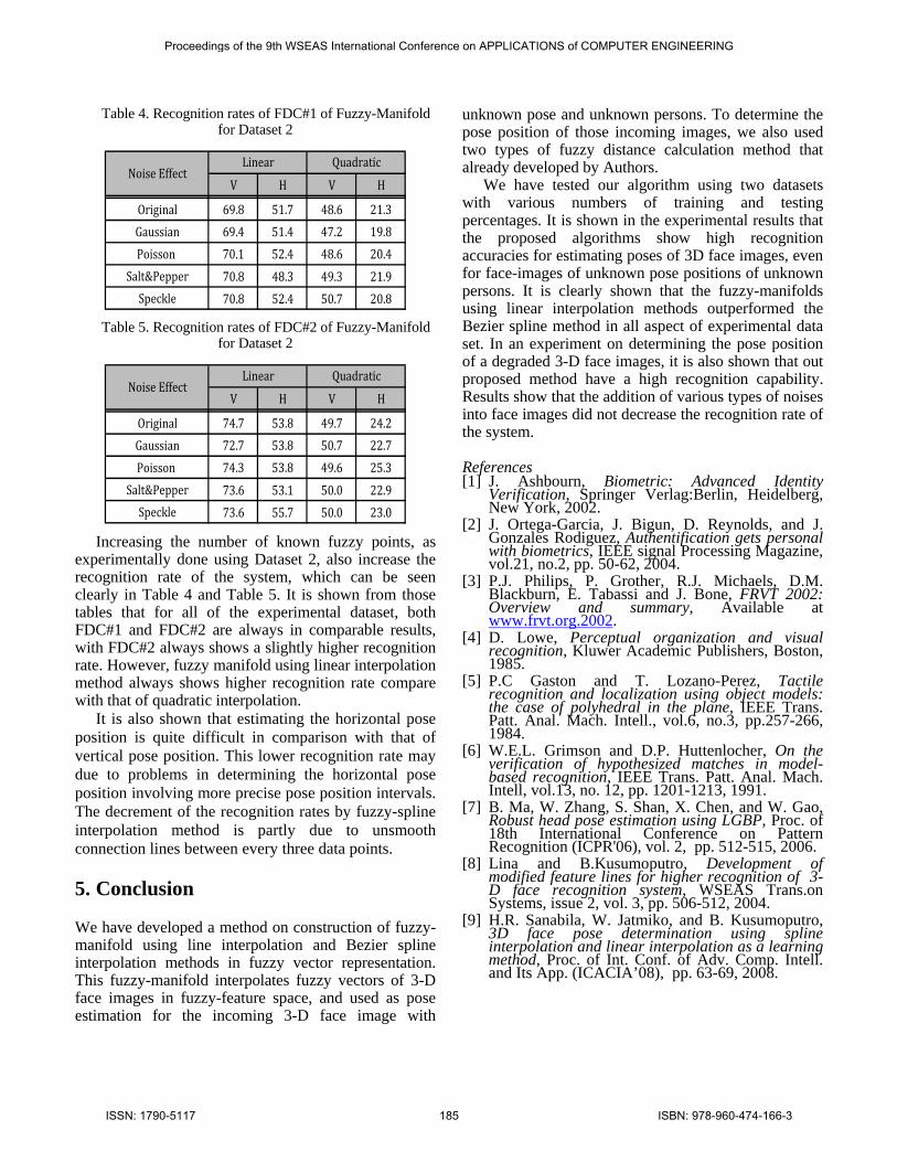
Table 4. Recognition rates of FDC#1 of Fuzzy-Manifold for Dataset 2
V H V H
Original 69.8 51.7 48.6 21.3Gaussian 69.4 51.4 47.2 19.8Poisson 70.1 52.4 48.6 20.4
Salt&Pepper 70.8 48.3 49.3 21.9Speckle 70.8 52.4 50.7 20.8
Linear QuadraticNoise Effect
Table 5. Recognition rates of FDC#2 of Fuzzy-Manifold for Dataset 2
V H V H
Original 74.7 53.8 49.7 24.2Gaussian 72.7 53.8 50.7 22.7Poisson 74.3 53.8 49.6 25.3
Salt&Pepper 73.6 53.1 50.0 22.9Speckle 73.6 55.7 50.0 23.0
Linear QuadraticNoise Effect
Increasing the number of known fuzzy points, as experimentally done using Dataset 2, also increase the recognition rate of the system, which can be seen clearly in Table 4 and Table 5. It is shown from those tables that for all of the experimental dataset, both FDC#1 and FDC#2 are always in comparable results, with FDC#2 always shows a slightly higher recognition rate. However, fuzzy manifold using linear interpolation method always shows higher recognition rate compare with that of quadratic interpolation.
It is also shown that estimating the horizontal pose position is quite difficult in comparison with that of vertical pose position. This lower recognition rate may due to problems in determining the horizontal pose position involving more precise pose position intervals. The decrement of the recognition rates by fuzzy-spline interpolation method is partly due to unsmooth connection lines between every three data points.
5. Conclusion
We have developed a method on construction of fuzzy-manifold using line interpolation and Bezier spline interpolation methods in fuzzy vector representation. This fuzzy-manifold interpolates fuzzy vectors of 3-D face images in fuzzy-feature space, and used as pose estimation for the incoming 3-D face image with
unknown pose and unknown persons. To determine the pose position of those incoming images, we also used two types of fuzzy distance calculation method that already developed by Authors.
We have tested our algorithm using two datasets with various numbers of training and testing percentages. It is shown in the experimental results that the proposed algorithms show high recognition accuracies for estimating poses of 3D face images, even for face-images of unknown pose positions of unknown persons. It is clearly shown that the fuzzy-manifolds using linear interpolation methods outperformed the Bezier spline method in all aspect of experimental data set. In an experiment on determining the pose position of a degraded 3-D face images, it is also shown that out proposed method have a high recognition capability. Results show that the addition of various types of noises into face images did not decrease the recognition rate of the system.
References [1] J. Ashbourn, Biometric: Advanced Identity
Verification, Springer Verlag:Berlin, Heidelberg, New York, 2002.
[2] J. Ortega-Garcia, J. Bigun, D. Reynolds, and J. Gonzales Rodiguez, Authentification gets personal with biometrics, IEEE signal Processing Magazine, vol.21, no.2, pp. 50-62, 2004.
[3] P.J. Philips, P. Grother, R.J. Michaels, D.M. Blackburn, E. Tabassi and J. Bone, FRVT 2002: Overview and summary, Available at www.frvt.org.2002.
[4] D. Lowe, Perceptual organization and visual recognition, Kluwer Academic Publishers, Boston, 1985.
[5] P.C Gaston and T. Lozano-Perez, Tactile recognition and localization using object models: the case of polyhedral in the plane, IEEE Trans. Patt. Anal. Mach. Intell., vol.6, no.3, pp.257-266, 1984.
[6] W.E.L. Grimson and D.P. Huttenlocher, On the verification of hypothesized matches in model-based recognition, IEEE Trans. Patt. Anal. Mach. Intell, vol.13, no. 12, pp. 1201-1213, 1991.
[7] B. Ma, W. Zhang, S. Shan, X. Chen, and W. Gao, Robust head pose estimation using LGBP, Proc. of 18th International Conference on Pattern Recognition (ICPR'06), vol. 2, pp. 512-515, 2006.
[8] Lina and B.Kusumoputro, Development of modified feature lines for higher recognition of 3-D face recognition system, WSEAS Trans.on Systems, issue 2, vol. 3, pp. 506-512, 2004.
[9] H.R. Sanabila, W. Jatmiko, and B. Kusumoputro, 3D face pose determination using spline interpolation and linear interpolation as a learning method, Proc. of Int. Conf. of Adv. Comp. Intell. and Its App. (ICACIA’08), pp. 63-69, 2008.
Proceedings of the 9th WSEAS International Conference on APPLICATIONS of COMPUTER ENGINEERING
ISSN: 1790-5117 185 ISBN: 978-960-474-166-3


![Chapter 3: Fuzzy Rules & Fuzzy Reasoning513].pdf · CH. 3: Fuzzy rules & fuzzy reasoning 1 Chapter 3: Fuzzy Rules & Fuzzy Reasoning ... Application of the extension principle to fuzzy](https://static.fdocuments.net/doc/165x107/5b3ed7b37f8b9a3a138b5aa0/chapter-3-fuzzy-rules-fuzzy-513pdf-ch-3-fuzzy-rules-fuzzy-reasoning.jpg)