DEVELOPMENT OF FOUR WHEELS SPACE-FRAME …umpir.ump.edu.my/8558/1/CD8037_@_68.pdf · DEVELOPMENT OF...
24
DEVELOPMENT OF FOUR WHEELS SPACE-FRAME HYBRID AIR MOTORCYCLE CHASSIS SER BENG SIAN This thesis is submitted as partial fulfillment of the requirements for the award of the degree of Bachelor of Mechanical Engineering with Automotive Engineering Faculty of Mechanical Engineering Universiti Malaysia Pahang JUNE 2013
Transcript of DEVELOPMENT OF FOUR WHEELS SPACE-FRAME …umpir.ump.edu.my/8558/1/CD8037_@_68.pdf · DEVELOPMENT OF...

DEVELOPMENT OF FOUR WHEELS SPACE-FRAME HYBRID AIR
MOTORCYCLE CHASSIS
SER BENG SIAN
This thesis is submitted as partial fulfillment of the
requirements for the award of the degree of
Bachelor of Mechanical Engineering with Automotive Engineering
Faculty of Mechanical Engineering
Universiti Malaysia Pahang
JUNE 2013

vi
ABTRACT
This project presents the development of four wheels space-frame hybrid air motorcycle
chassis. Studies were made to investigate the computational stress/strain analysis and
fabricate the four wheel space-frame hybrid air motorcycle chassis. With the rapid
growth of vehicle availability and usage on the road in recent year, the rate of pollution
is increasing. To alleviate the problem, four wheels space-frame hybrid air motorcycle
has been developed. The hybrid air motorcycle is one kind of hybrid vehicle. It needs a
lightweight and strong chassis to support the weight of the engine, drive-train
compartment, driver, and other overall packaging system. A whole new compact
motorcycle chassis design was undergone a various type of testing simulation by using
FEA software. The simulation data such as stress, strain, displacement and factor of
safety (FOS) were utilized as a guideline to develop and fabricate a new design of four
wheels space-frame hybrid air motorcycle chassis. As a conclusion, the objective was
achieved where the simulation results show that the chassis design will not provide
significant affect neither to the chassis structure nor the driver.

vii
ABSTRAK
Projek ini membentangkan pembangunan empat roda Ruang-rangka hibrid udara
motosikal casis. Kajian telah dibuat untuk menyiasat stres/tekanan pengiraan analisis
dan membina kerangka motosikal hibrid empat roda Ruang-rangka. Dengan
pertumbuhan pesat adanya kenderaan dan penggunaan di jalan raya kebelakangaan ini,
kadar pencemaran semakin meningkat. Bagi mengatasi masalah ini, empat roda
motosikal udara Ruang-rangka hibrid telah dibinakan. Motosikal hibrid merupakan
salah satu jenis kenderaan hibrid. Ia memerlukan kerangka yang ringan dan kuat untuk
menyokong berat enjin, gearbox, pemandu, dan sistem lain. Reka bentuk baru motosikal
casis ini akan menjalani beberapa jenis ujian simulasi dengan menggunakan perisian
FEA. Keputusan simulasi seperti tekanan, ketegangan, anjakan, dan factor keselamantan
telah digunakan untuk sebagai satu garis panduan untuk membangunkan dan boleh
mencipta reka bentuk empat road ruang-rangka hybrid udara motosikal casis yang baru.
Kesimpulannya, objektif telah dicapai sebagaimana keputusan simulasi telah
menunjukkan reka bentuk yang baru ini tidak akan menimbulkan kesan kepada struktur
casis dan pemandu.

viii
TABLE OF CONTENT
Page
DECLARATION BY SUPERVISOR ii
DECLATATION BY STUDENT iii
DEDICATION iv
ACKNOWLEDGEMENT v v
ABSTRACT vi
ABSTRAK vii vi
TABLE OF CONTENT viii
LIST OF TABLES xi
LIST OF FIGURES xii
LIST OF SYMBOLS xiv
LIST OF ABBREVIATIONS xv
CHAPTER 1 INTRODUCTION
1.1 Introduction 1
1.2 Problem Statement 2
1.3 Objective 3
1.4 Work Scope 3
1.5 Hypothesis 3
1.6 Flow Chart 4
1.7 Gantt Chart 5
CHAPTER 2 LITERATURE REVIEW
2.1 Fundamental of Chassis 6
2.1.1 Evolution from Two-Wheel Design to
Four-Wheel Design 8
2.1.2 Classification of Chassis 8
2.1.3 Space-frame Consideration 9
2.2 Chassis for Hybrid Motorcycle 10

ix
2.3 Importance of Ergonomics Chassis Design 11
2.4 Type of Analysis 13
2.4.1 Finite Element Analysis Method 13
2.4.2 Experimental Modal Analysis 14
CHAPTER 3 METHODOLOGY
3.1 Concept of Air Hybrid Four Wheels Motorcycle Chassis 16
3.2 Design Sketching 16
3.3 Design Consideration 17
3.4 3D Drawing Process 19
3.5 Software Computational Analysis 19
3.6 Simulation of Loading Constraint 20
3.6.1 Static Load Constraint 21
3.6.2 Deceleration Constraint 22
3.6.3 Acceleration Constraint 24
3.6.4 Frontal Impact Constraint 26
3.7 Material Selection 27
3.7.1 Stainless Steel AISI 304 27
3.8 Fabrication Equipment 30
3.9 Fabrication Process 33
3.9.1 Cutting 34
3.9.2 Bending 34
3.9.3 Notching 37
3.9.4 Welding 38
3.10 Governing Equation for Stress/Strain 39
CHAPTER 4 RESULT AND DISCUSSION
4.1 Finite Element Analysis 41
4.1.1 Static Load Constraint 44
4.1.2 Deceleration Constraint 48
4.1.3 Acceleration Constraint 51
4.1.4 Frontal Impact Constraint 55
4.2 Fabrication Result 58

x
CHAPTER 5 CONCLUSION AND RECOMMENDATION
5.1 Conclusion 59
5.2 Recommendation 60
REFERENCES 61
APPENDICES 63
A Gantt Chart 63
B Drawing Design 64
C Fabrication Image 66
xi
LIST OF TABLE
Table No. Page
3.1 Anthropometric Data 18
3.2 Force Distribution of Static Load Constraint 21
3.3 Force Distribution of Deceleration Constraint 23
3.4 Force Distribution of Acceleration Constraint 25
3.5 Force Distribution of Frontal Impact Constraint 27
3.6 The percentage of the element in the stainless steel 27
3.7 Properties of stainless steel AISI 304 28
3.8 Function and List of Apparatus 30
3.9 List of Stainless Steel Tube 36

xii
LIST OF FIGURES
Figure No. Page
2.1 First motorcycle in year 1894 7
2.2 Total Design Process Model 12
2.3 Stress Analysis Diagram 14
2.4 Test System Theory Diagram 15
3.1 Seated Position of Human 17
3.2 Chassis with Fix Geometry and Static Load 21
3.3 Chassis with Fix Geometry and Deceleration Loads 22
3.4 Chassis with Fix Geometry and Acceleration Loads 24
3.5 Chassis with Fix Geometry and Frontal Impact Loads 26
3.6 Stainless Steel AISI 304 29
3.7 Rotary Disc Cutter 31
3.8 Bending Machine 31
3.9 Hand Grinder 32
3.10 Metal Inert Gas Welding Machine 32
3.11 Jig for 4 wheels Motorcycle Chassis 33
3.12 3D Model with List of Stainless Steel Tube 35
3.13 Notching 37
3.14 Tab Weld Chassis 38
4.1 Isometric View of 3D Model Chassis 42
4.2 Top viw of 3D Model Chassis 43
4.3 Front viw of 3D Model Chassis 43
4.4 Side viw of 3D Model Chassis 44

xiii
4.5 Stress Analysis for Static Load Constraint 45
4.6 Critical Point I 45
4.7 Critical Point II 46
4.8 Strain Analysis for Static Load Constraint 47
4.9 Displacement Deflection for Static Load Constraint 47
4.10 Stress Analysis for Deceleration Constraint 48
4.11 Critical Point I 49
4.12 Critical Point II 49
4.13 Displacement Deflection for Deceleration Constraint 50
4.14 Strain for Deceleration Constraint 51
4.15 Stress Analysis for Acceleration Constraint 52
4.16 Critical Point I 52
4.17 Critical Point II 53
4.18 Displacement Deflection for Acceleration Constraint 54
4.19 Strain for Acceleration Constraint 54
4.20 Stress Analysis for Frontal Impact Constraint 55
4.21 Critical Point 56
4.22 Displacement Deflection for Frontal Impact Constraint 51
4.23 Strain for Frontal Impact Constraint 52
4.24 Completed Chassis 58hu

xiv
LIST OF SYMBOLS
Stress
Yield strength
Von Mises Stress
Strain

xv
LIST OFABBREVIATIONS
AISI American Iron and Steel Institute
CAE Computational Aided Engineering
FEM Finite Element Method
FOS Factor of Safety
HFE Human Factors and Ergonomics
IC Internal Combustion
IEA International Ergonomics Association
MIG Metal Inert Gas Welding’
SAE Automotive Engineering Society
3D Three Dimensional

CHAPTER 1
INTRODUCTION
1.1 BACKGROUND STUDY
In the automotive field, the chassis is one of the important parts of a vehicle
include motorcycling. Basically, the motorcycle chassis has 2 basic types. There are
static type and dynamic type (Tony Foale, 2002). In the static type, the chassis must be
able to support the weight of the components of the vehicle such as engine, transmission,
and other necessary systems. The material selection of the chassis is also very vital. A
strong strength material must be used for the main frame to avoid crash easily when
crashing occurs. For the frame dynamic’s function, it is not very obvious but it is very
important for the comfort, handling, stability and road holding.
Over the years, the design of the motorcycle chassis has been developed rapidly.
The first motorcycle chassis is based on the bicycle chassis which is diamond-shaped
structure with tubes brazed into the lugs (Tony Foale, 2002). However, the earlier
motorcycle required a small size low-powered engine and this engine need to fix in the
diamond-shape structure chassis. Thus, the chassis had modified to mount the small
low-powered engines. Currently, there is various types of motorcycle chassis had been
used in this world. These different types of chassis have their own functionality and also
the limitation. It is all depend on what type of motorcycle will use what kind of chassis.
For example, frontbone type chassis design is generally associated with Greeves
motorcycles and step through type chassis design is used for scooters or low priced
commuter bikes.

2
In recent year, the demand of hybrid motorcycle has been increased from time to
time in the modern world. Hybrid engine motorcycle configured travel by using driving
of an electric motor. This hybrid is not longer to replace the usage of internal
combustion engine. The internal combustion engine required fuel and will produce
harmful gas to the environment. By using a hybrid engine motorcycle, the emission
from the engine will be much less. However, to build a hybrid engine on the motorcycle
chassis, the design of the chassis need to modified. As known, the hybrid engine
required more components compared to the IC engine. So, the chassis of the hybrid
motorcycle must be bigger than the IC engine motorcycle chassis, thus the components
can install on the motorcycle chassis.
1.2 PROBLEM STATEMENT
The development of the motorcycle chassis is surprisingly fast and the weakness
of the chassis is also improved. Nowadays, the automotive technology is very advanced.
The chassis that had manufacture is using strong strength material. Normally, the
material that used for the motorcycle chassis is aluminum, alloy, and steel. These
materials have high yield strength to support higher weight of the vehicle components
especially for the hybrid engine type motorcycle.
Nowadays, there is a lot of the type of research about the chassis such as finite
element method and the experimental modal analysis technique to analysis the
limitation of chassis. Analysis of the chassis can analyze the vibration, fatigue and other
properties of the product and also the weak link of the product structures (Shi and Wang,
2010). These two of analysis can give a guide to manufacture a stronger chassis as well
as provide the reliable basis for the improvement of the product. Thus, before
manufacture a new design of motorcycle chassis, this analysis is very useful and
important for the safety of the user.

3
However, the chassis of hybrid engine and chassis of IC engine is not the same.
There are a lot of components with a hybrid engine. With the number of components
need to attach together on the chassis, obviously, the chassis will be bigger compared to
the IC engine. To attach all the components, the arrangement of the components will be
very compact and the weight of the motorcycle is also heavier than the IC engine
chassis.
1.3 OBJECTIVES
a. To design and fabricate four wheels air hybrid space-frame motorcycle chassis.
b. To analyze computational stress/strain analysis of the four wheels air hybrid
space-frame motorcycle chassis.
1.4 WORK SCOPES
a. Literature review on four wheels motorcycle design, chassis, suspension system.
b. Conceptual design of air hybrid motorcycle chassis.
c. Computational stress/strain analysis and design refinement.
d. System component preparations and chassis fabrication.
e. System integration
f. Final report preparation.
1.5 HYPOTHESIS
Proposed four wheels space frame hybrid air motorcycles take additional
consideration of compact components packaging system as well as large powertrain
compartment compared with conventional four wheels system. By the end of the
development, the hybrid motorcycle design features with detail material selection and
stress-strain analysis could enhance the development of innovated motorcycle chassis
prototype.

4
Yes
Yes
No
No
1.6 FLOW CHART
Start
Literature review about the chassis
Sketching chassis design and
material selections
SolidWork
Drawing
Approval
Fabrication Chassis
Data analysis and Simulation
Operational
Final report presentation
End

5
1.7 GANTT CHART
The Gantt chart is refer to Appendix A

CHAPTER 2
LITERATURE REVIEW
2.1 FUNDAMENTAL OF CHASSIS
Nowadays, motorcycle is widely used on the road. The development of the
motorcycle has been quite fast since 1900’s. From mini size motorcycle until the racing
type motorcycle, the changes of the motorcycle are very obvious. Indirectly, the
technology of the motorcycle chassis is also become advance and able to manufacture
different design of motorcycle chassis.
A well designed motorcycle chassis, it is important to ensure that the safety,
performance, and fuel efficiency. A good chassis is able to protect the passenger from
injury when a crash occurs. For the fuel efficiency aspect, the chassis is light enough
and it has a low frictional resistance (Hanif and Amir, 2012).
In the motorcycle industry field, all the components of the motorcycle and the
load will attach to the motorcycle chassis. The load includes the weight if each
component and the forces which manifest during acceleration, deceleration and
cornering. The components that usually attached to the chassis are the engine, the
suspension system, the steering system and the braking system (Hanif and Amir, 2012).
Motorcycle chassis is not similar to the car chassis. The size of the motorcycle chassis is
much smaller than car chassis. Thus, every component must be compact between each
other and attach to the motorcycle chassis.
Over the years, designers have been repeatedly criticized for their seeming
reluctance to depart from the diamond-pattern frame inherited from the pedal cycle
7
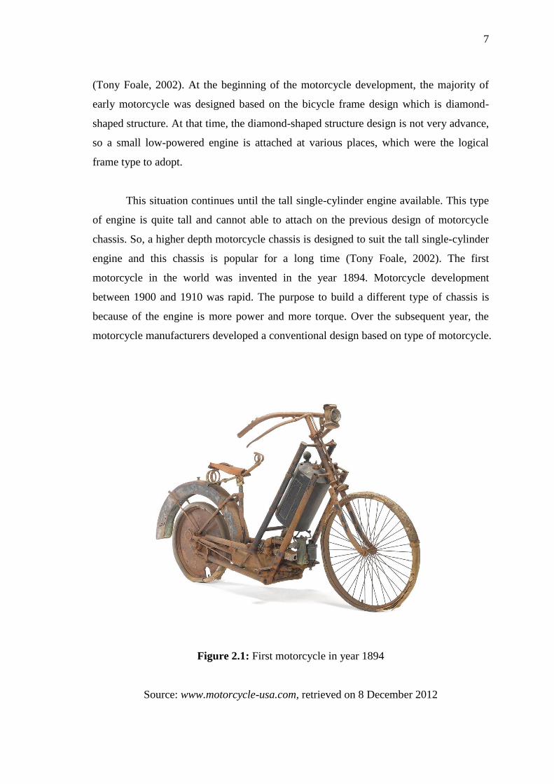
(Tony Foale, 2002). At the beginning of the motorcycle development, the majority of
early motorcycle was designed based on the bicycle frame design which is diamond-
shaped structure. At that time, the diamond-shaped structure design is not very advance,
so a small low-powered engine is attached at various places, which were the logical
frame type to adopt.
This situation continues until the tall single-cylinder engine available. This type
of engine is quite tall and cannot able to attach on the previous design of motorcycle
chassis. So, a higher depth motorcycle chassis is designed to suit the tall single-cylinder
engine and this chassis is popular for a long time (Tony Foale, 2002). The first
motorcycle in the world was invented in the year 1894. Motorcycle development
between 1900 and 1910 was rapid. The purpose to build a different type of chassis is
because of the engine is more power and more torque. Over the subsequent year, the
motorcycle manufacturers developed a conventional design based on type of motorcycle.
Figure 2.1: First motorcycle in year 1894
Source: www.motorcycle-usa.com, retrieved on 8 December 2012
8
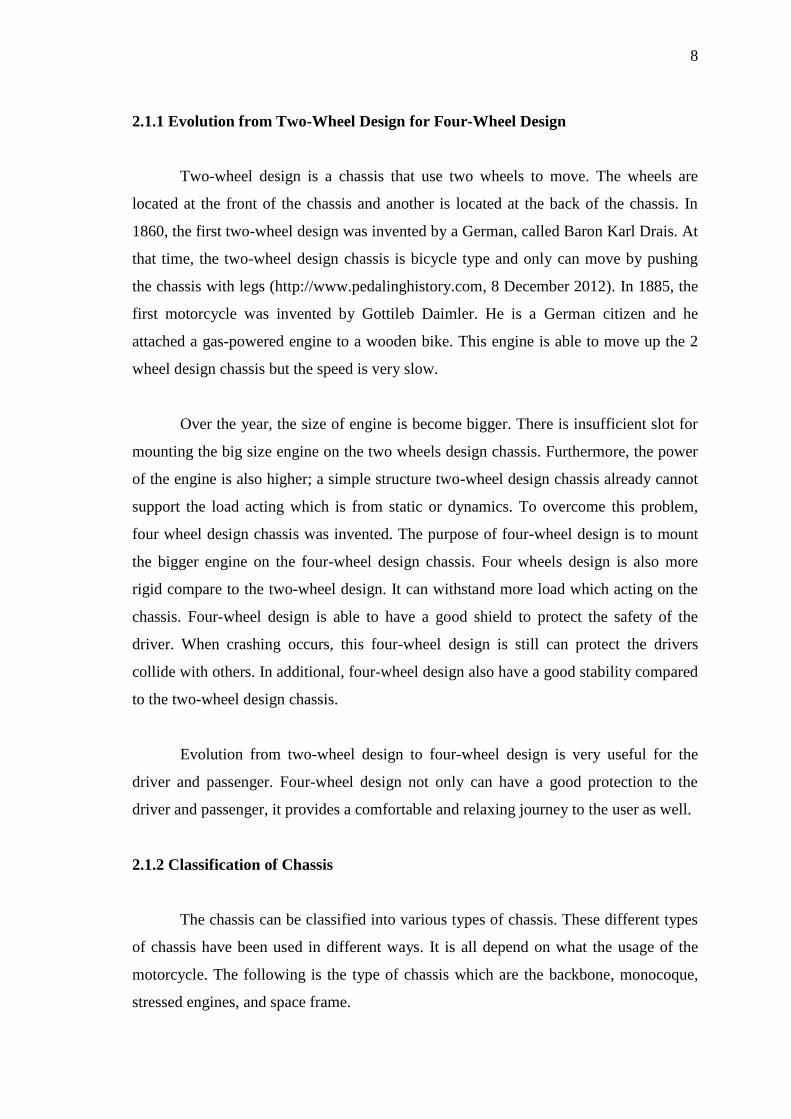
2.1.1 Evolution from Two-Wheel Design for Four-Wheel Design
Two-wheel design is a chassis that use two wheels to move. The wheels are
located at the front of the chassis and another is located at the back of the chassis. In
1860, the first two-wheel design was invented by a German, called Baron Karl Drais. At
that time, the two-wheel design chassis is bicycle type and only can move by pushing
the chassis with legs (http://www.pedalinghistory.com, 8 December 2012). In 1885, the
first motorcycle was invented by Gottileb Daimler. He is a German citizen and he
attached a gas-powered engine to a wooden bike. This engine is able to move up the 2
wheel design chassis but the speed is very slow.
Over the year, the size of engine is become bigger. There is insufficient slot for
mounting the big size engine on the two wheels design chassis. Furthermore, the power
of the engine is also higher; a simple structure two-wheel design chassis already cannot
support the load acting which is from static or dynamics. To overcome this problem,
four wheel design chassis was invented. The purpose of four-wheel design is to mount
the bigger engine on the four-wheel design chassis. Four wheels design is also more
rigid compare to the two-wheel design. It can withstand more load which acting on the
chassis. Four-wheel design is able to have a good shield to protect the safety of the
driver. When crashing occurs, this four-wheel design is still can protect the drivers
collide with others. In additional, four-wheel design also have a good stability compared
to the two-wheel design chassis.
Evolution from two-wheel design to four-wheel design is very useful for the
driver and passenger. Four-wheel design not only can have a good protection to the
driver and passenger, it provides a comfortable and relaxing journey to the user as well.
2.1.2 Classification of Chassis
The chassis can be classified into various types of chassis. These different types
of chassis have been used in different ways. It is all depend on what the usage of the
motorcycle. The following is the type of chassis which are the backbone, monocoque,
stressed engines, and space frame.

9
Backbone – typically utilizes a large section top tube which, in some cases,
doubled up as an oil carrying member.
Monocoque – using different type of material for the constructions. Normally,
this motorcycle chassis is manufactured for the road racers, street bikes and
scooters.
Stressed engines – using the engine and gearbox as a stressed member of the
chassis has been used extensively on the motorcycles.
Spaceframe – the shape of the spaceframe is likely a”cage: which welded
together with square hollow tubes or circle hollow tubes.
2.1.3 Space-frame Consideration
Space-frame type design chassis can provide a good result in torsional rigidity,
weight holding, and impact protection (Keith, 2009). To build a well-designed
spaceframe, triangulation is very important and must always in the consideration.
Therefore, to build the chassis structure is more rigid, the motorcycle chassis must be as
wide as possible.
At the earliest motorcycle, the chassis is design of space-frame chassis. Space-
frame chassis is easy to build and it is strong enough to support the weight of the
components. There are 2 advantages of space-frame: chassis weight and chassis
stiffness.
Normally, the motorcycle chassis that design of the space frame is lightweight.
With a lightweight chassis, the motorcycle can reduce emissions and increase the fuel
efficiency. For the lightweight motorcycle, there is no many additional features such as
power steering, which in turn reduces overall load carrying requirements; thus setting in
motion a cycle of weight-saving initiative and reducing vehicle complexity (Howard,
2000).
Lightweight is a primary goal for all race cars as lightweight only required less
force to accelerate by the same amount. According to the newton's 2nd
law, the
10
acceleration of a body is parallel and directly proportional to the net force acting on the
body. If in the direction of the net force, the net force is inversely proportional to the
mass of the body. The following is the equation of newton's 2nd
law as expressed in Eq.
(2.1):
(2.1)
From the equation, if the same force is applied to the car, the lighter car will
accelerate faster than heavier car. This is the reason the racing car is fabricating space
frame type chassis. (Brendan. J. Waterman, 2011)
Besides the weight of the chassis, stiffness of the chassis must be considered. A
well-built chassis required a high stiffness to protect damaging to the chassis. Thus,
choosing a high stiffness material is the key in order to build out a chassis which is
space frame type chassis. Stiffness material is also known as Young’s Modulus. The
mechanism for stiffness in a material is the inter-molecular force, so this stiffness
cannot be modified by any mechanical or chemical processes (Brendan, 2011). The
stiffness of the material can be calculated from the equation as expressed in Eq. (2.2)
E =
=
=
(2.2)
2.2 CHASSIS FOR HYBRID MOTORCYCLE
To design a chassis which is hybrid type, there are many aspects to be
considered, including component packaging, material selection, strength, and weight
(Michael and Terry, 2009). Firstly, before the chassis can be developed, it is first
important to understand what hybrid engine component will be used and attached to the
motorcycle chassis. The number of hybrid engine components is much more than IC
engine, so the location of the attachment of the components must be identified so that
the load acting on the chassis capable of withstanding.

11
Secondly, the key design of the chassis is the material selection. Normally, the
material has been chosen is stainless steel. Stainless steel is better than other materials
because stainless steel has better expansion and contraction. This property allows
bending and curving is much easier if compared to other type of material.
Thirdly, chassis for hybrid motorcycle required a high strength to protect the
component packaging and the passenger. As mentioned, there is a lot of hybrid engine
component. The weight of the component adds up together will give a load acting on the
chassis. So, the strength of the chassis must be strong enough to withstand the weight of
the components.
The last aspect is weight. The purpose of hybrid engine motorcycle is to replace
the IC engine so that emission can be reduced. However, the power of hybrid engine is
not as high as IC engine, thus, the weight of the chassis of hybrid motorcycle needs to
minimize in order to increase the speed of the motorcycle.
2.3 IMPORTANCE OF ERGONOMICS CHASSIS DESIGN
Design and ergonomics are the most important terms in the design process.
According to the international ergonomics association (IEA), ergonomics as the
discipline that involves the understanding of the interaction between humans and other
elements of a system and the profession that applies theory, principles, data and
methods to designing in order to optimize human well-being and overall system
performance (Karmegam Karyppiah, Mohd Sapuan, Mohd Yusof, Napsiah Ismail,
ShamsulTamrin, 2011).
The four basic criteria in an ergonomic chassis design are increasing production,
decreasing injuries, decreasing human error and increasing user satisfaction. An
ergonomic chassis design can give the human comfort, clear vision, safety, as well as
reduce fatigue during the reading process.
The Applied Human Factors and Ergonomics (HFE) design and engineering
continue to permeate the manufacturing industry. One of the most commonly

12
experienced applications of ergonomics design and engineering resides in the
automotive. The development in ergonomic cockpit, instrument, seating, and safety
design are all the evidence in practically every new automobile (Robert, 2002).
The development of applied human factor and ergonomics (HFE) motorcycle
chassis design has still remained an engineering challenge. The motorcycle unlike other
automotive, motorcycle is an unconstrained vehicle platform, saddle-based vehicle
which does not offer lumbar, thoracic or thigh support (Robert, 2002). To design an
ergonomics chassis, there are six important components; market study, product design
specification, conceptual design, manufacturing, and lastly sale. The Figure 2.2 is the
total design process model:
Figure 2.2: Total Design Process Model
Source: Karmeganm, Sapuan, Yusof, NapsiahShamsul (2011)

13
2.4 TYPE OF ANALYSIS
The chassis is to use to support all the components such as engine compartment,
drivers and other packaging components. The force of chassis mainly includes the
gravity of the components, the weight of the driver, and acceleration force during the
process of running (Wang, Liu, Zeng, Chen, 2012). Because of these criteria the
strength and the rigidity of the chassis must be considered during the structure of the
design. Normally, to determine the strength and rigidity of the chassis, there are two
types of analysis can be obtain to know that the stress and strain of the chassis. These
two analyses are finite element method and the experimental modal analysis technique.
2.4.1 Finite Element Analysis Method
Finite Element Analysis is a kind of mathematical approximation method, which
can simulate the true physical phenomena. The simulation will analysis the 3D model in
the software which in geometry and loading condition. From the FEM method, the
value and position of maximum stress and maximum strain will be obtained and show
clearly on the 3D model. The range of stress and strain will also show on the structure
of the model represented by different color. The color close to red (shown in Figure 2.3)
means the stress or strain is nearly close to the maximum value while the color closest
to blue (shown in Figure 2.3) means the stress or strain is in very small value and can be
ignored.